

Page 1

28EXT External Emitter Adapter
INSTALLATION INSTRUCTIONS
DESCRIPTION
The 28EXT External Emitter Adapter is placed between a Xantech IR system and a list of approved
electronic equipment that feature a rear panel IR input jack. These input jacks accept electrical IR
commands without the carrier frequency, and are therefore not compatible with full range IR Receivers that
output a carrier frequency along with the IR commands, such as all Xantech IR Receivers. The 28EXT
interfaces and adapts a Xantech IR receiver to these rear panel IR inputs.
INSTALLATION
• Before making any connections:
• Confirm that the source equipment to be controlled is one of the devices in table A below.
• Table A below may indicate the need for a Wire-Swap Connector for some source units. If your device
to be controlled requires this connector, make sure that it is securely plugged into the 28EXT output
connector (the one with the black connector and the warning tag). Otherwise damage to your source
unit or the 28EXT may occur, and such damage will not be covered under warranty.
• The 28EXT may not be compatible with non-Xantech IR Receivers and Connecting Blocks.
TABLE A:
APPLICATION #1 – XANTECH®
Models:
HDMI3x1, HDMI4x1, HDMI4x4, WIC1200
Connector marking: EXT IR or IR In
APPLICATION #2 – GEFEN®
Model:
Any product that uses RMT-IR Extender (for
example: 3x1, 4x1, 4x4 HDMI switchers)
Connector marking: EXT IR
APPLICATION #3 – OMNIMOUNT® PANEL MOUNTS
Model: Motion52 Motorized Mount
Connector marking: R/C
APPLICATION #4 – SIRIUS® SATELLITE TUNERS
Model:
SCH2P Sirius Connect Home Pro Tuner
Polk Audio®/Sirius SR-H1000 Home Tuner
Connector marking: IR INPUT
TIP SIGNAL
RING +5VDC Power
SLEEVE GROUND
Wire-Swap Connector Not Required
TIP SIGNAL
RING +5VDC Power
SLEEVE GROUND
Wire-Swap Connector Not Required
TIP SIGNAL
RING +5VDC Power
SLEEVE GROUND
Wire-Swap Connector Not Required
TIP +5VDC Power
RING SIGNAL
SLEEVE GROUND
Wire-Swap Connector Required
Page 2
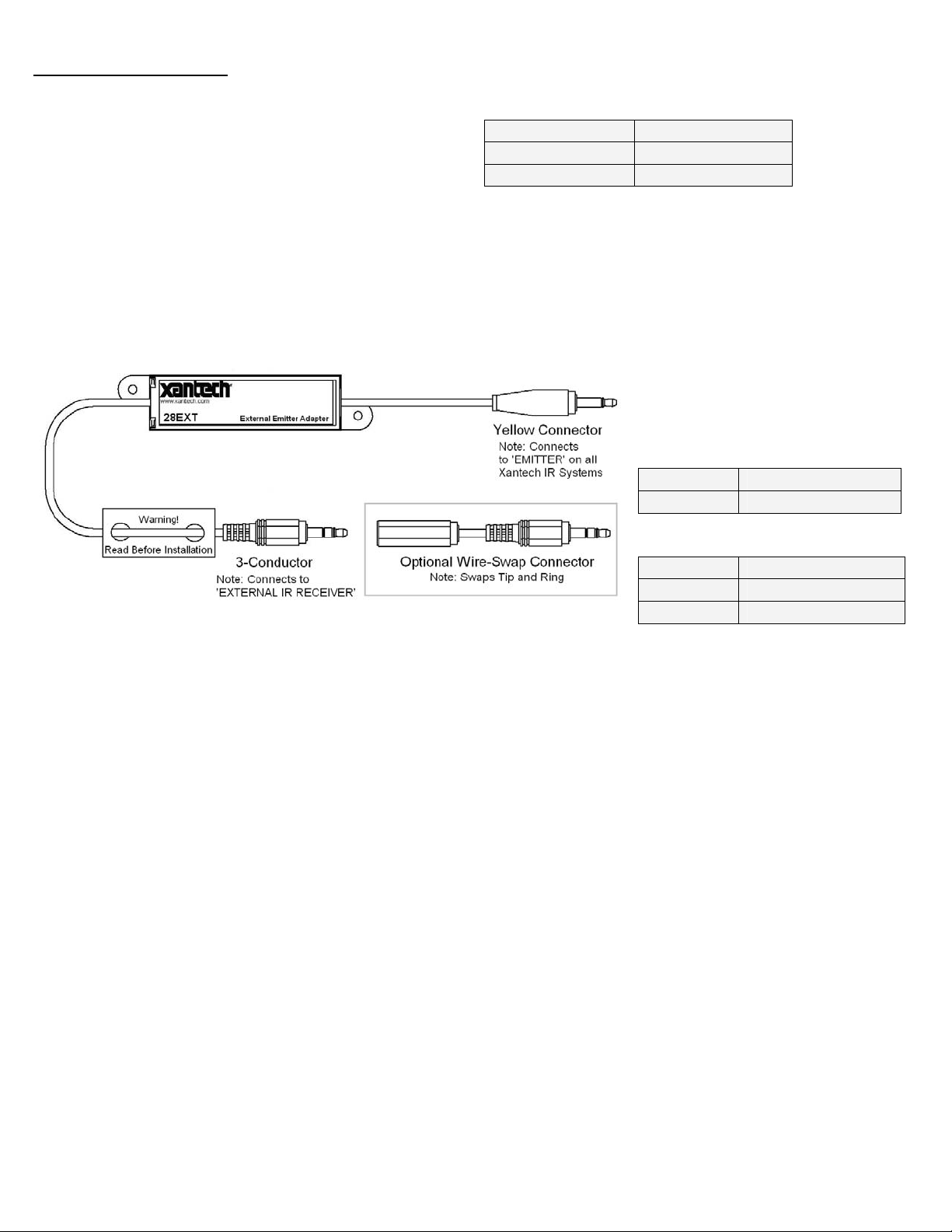
TABLE A (continued):
APPLICATION #5 – VERIZON® FiOS™ MOTOROLA® RECEIVERS
Model:
QIP7000 Series
Connector marking: IR RECEIVER INPUT
TIP +5VDC Power
RING SIGNAL
SLEEVE GROUND
Wire-Swap Connector Required
CONNECTIONS
• Connect the 28EXT output, using the Wire-Swap Connector if required, to the equipment’s IR input.
• Connect the 28EXT input to a Xantech IR system’s connecting block. The yellow plug should connect to
the yellow connector (emitter connection).
TABLE B:
28EXT Input and Output
Connector Pin Assignments:
INPUT – 3.5mm Mono Male
TIP IR SIGNAL IN
SLEEVE GROUND
OUTPUT – 3.5mm Stereo Male
TIP IR SIGNAL OUT
RING +5VDC Power
SLEEVE GROUND
• Make sure the source unit is on and the Xantech connecting block and IR receiver are powered.
• Direct a remote control towards the IR receiver connected to the IR system and make sure the
electronic equipment responds.
Limited Warranty
Xantech® warrants its products to be free of defects in materials or workmanship. This is a Limited Lifetime warranty from the
date of purchase by the original consumer. Any products returned to Xantech and found to be defective by Xantech within the
warranty period will be repaired or replaced, at Xantech’s option, at no charge. Xantech will not be responsible for the actual cost
of installation or removal of the product, nor for any incidental or consequential damages. Some states d o not allow the
exclusion or limitation of incidental or consequential damages, so the above limitation may not apply to you. This warranty gives
you specific legal rights. You may have additional legal rights that vary from state to state.
Xantech Corporation
13100 Telfair Ave. Sylmar CA 91342 | Xantech.com
Installation Instructions, 28EXT © 2009 Xantech Corporation
Document # 08905197B
All registered trademarks and trademarks (SIRIUS, GEFEN, OMNIMOUNT, VERIZON, VERIZON FIOS, MOTOROLA, POLK
AUDIO) are the property of their respective owners. All other marks are registered trademarks and trademarks of Xantech
Corporation. All rights reserved.
This document is copyright protected. No part of this manual may be copied or reproduced in any form without prior written
consent from Xantech Corporation. Xantech Corporation shall not be liable for operational, technical, or editorial
errors/omissions made in this document.
 Loading...