

Page 1
INSTALLATION INSTRUCTIONS
VCIR-CFL
™
MATCH MAKER™ SPEAKER VOLUME CONTROL
WITH IR RECEIVER
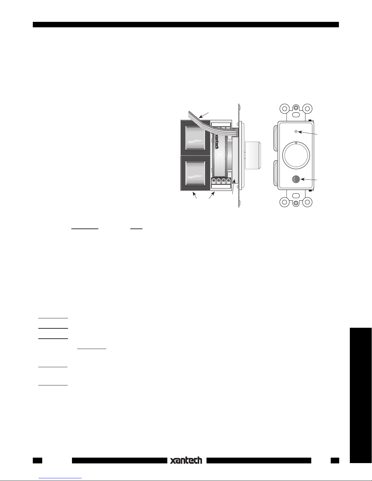
The Model VCIR-CFL is an impedance matching stereo speaker volume control combined
with a "CFL Friendly" IR Receiver. It mounts in
a single gang J-box. The volume control section has the same impedance matching capabilities as that of the Xantech Model 760-00
Match Maker volume control. The IR Receiver
section has similar performance to that of the
480-80 CFL Dinky Link IR Receiver with the
4-Conductor 18" Ribbon
Cable for IR Receiver.
OUTPUT
L+ L– R– R+
VCIR
™
SPEAKER VOLUME CONTROL
WITH IR RECEIVER
®
SYLMAR, CA
Dual LED
Red-Talkback
Green-Status
added feature of a STATUS LED for system
ON/OFF indication.
CAUTION:
The VCIR-CFL is designed to
control products that operate with 36 to 42
kHz IR Carriers only!
NOTE: The volume control section of the
VCIR-CFL is manually controlled only.
The IR
INPUT
IR Receiver
Stereo Volume Control
Section (auto-former)
Section
Fig. 1 The VCIR-CFL
L+ L– R– R+
IR Receiver
Photo Diode
Receiver section is for control of other system components -- it cannot control the volume control
section!
SPECIFICATIONS – VOLUME CONTROL SECTION
• Type: 2 channel TRI-FI™ wound precision autoformers, with independent gnds.
• Terminals: Plug-in type screw terminals.
• Power Rating: 25 Watts continuous, 150 Watts peak.
• Freq. Response: 20-20,000 Hz ± 1dB at 1 watt.
• Attenuation: 11 steps at 3 to 6 dB per step - 35 dB max. (Max. CCW is OFF).
S1 setting: 0 dB @ Max. CW (pass-through position).
S4 setting: 9 dB @ Max. CW.
S8 setting: 13 dB @ Max. CW.
• Impedance:
S1 setting: Pass-through position. i.e. 8 Ohms on OUTPUT reflects 8 Ohms to INPUT (Max.
CW position).
S4 setting: 8 Ohms on OUTPUT reflects 32 Ohms to INPUT . Likewise, 4 Ohms on OUTPUT reflects 16
Ohms to INPUT (Max. CW position).
S8 setting: 8 Ohms on OUTPUT reflects 64 Ohms to INPUT. Likewise, 4 Ohms on OUTPUT reflects 32
Ohms to INPUT (Max. CW position).
• Mounting: Fits most new construction junction boxes - uses single space.
NOTE: It may be necessary to cut off the back portion of a J-box or use a "P" ring to have sufficient room.
Be sure to check fit before choosing J-boxes!
• Dimensions: 1-5/8" (41.3mm) W x 2-7/8" (73mm) H x 2-7/16" (62mm) D
Speakers & Volume Controls
VCIR-CFL
1
Page 2
SPECIFICATIONS – IR RECEIVER SECTION
• Infrared carrier frequency bandwidth: 36 kHz to 42 kHz.
• IR reception range: Up to 60 feet on axis (range may be more or less depending on device being
controlled and levels of IR or EM interference).
• Reception angle: Approx. 50% range reduction @ ±45° off axis horizontally.
• Cable requirements: When running long lengths use:
4-conductor/24 gauge solid or stranded wire up to 200', 22 gauge up to 600', 20 gauge up to 2000' and
18 gauge up to 5000' (unshielded OK).
• Maximum cable length: One mile with 18 gauge.
• 4-Terminal Block (with double sided tape for mounting) included for easy extension of 18" ribbon lead.
See Fig. 6 for lead identifications.
• Red talkback LED: Tests system for correct wiring and indicates IR reception.
• Green system ON/OFF status LED: (draws 10 mA @ 12 VDC).
• SUN780 Sunscreen filters available separately. Order these to help with sunlight and stray IR problems.
They fit easily over rear of photodiode opening.
• IR receiver works in normal 3-wire mode with 4th lead for Status.
• NOTE:
Unit will not work in Phantom mode!
• Use Xantech Connecting Blocks for connection to emitters.
• Power requirements: 12 Volts DC ± 2 V @ 20 mA.
• Up to 10 VCIR-CFL's may be powered by one 781RG power supply.
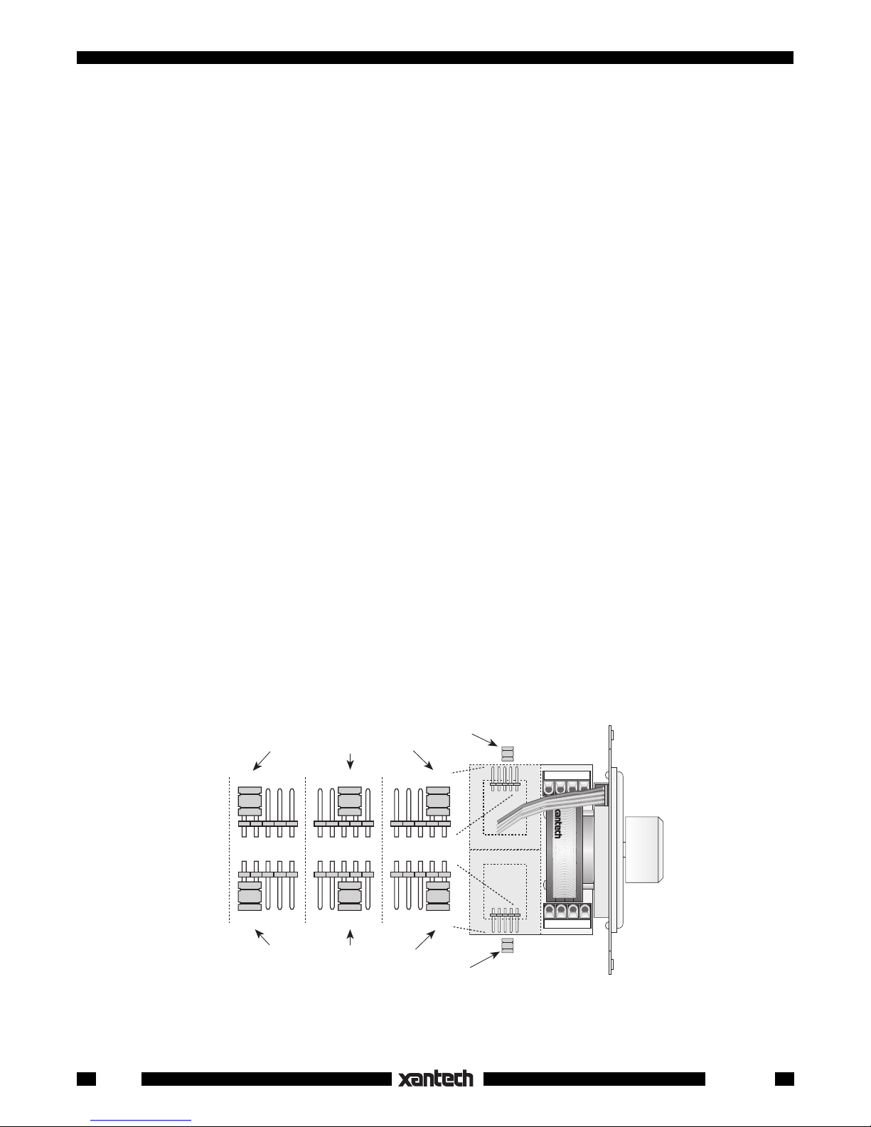
SETTING THE IMPEDANCE MATCHING JUMPERS
Fig. 2 shows the location of the pins and the jumper locations on the pins for the three impedance multiplier
positions. To set the jumpers correctly, refer to Fig. 2 and the charts and procedures that follow.
The jumpers are located under the one side of the autoformers as shown in Fig.2. Their proper placement
depends on the number of VCIR's and speakers used in the total installation. To set them for the best
impedance matching condition, refer to the charts and procedures that follow.
Left Channel Jumper
Left Channel Jumper Positions
S8
S8
Right Channel Jumper Positions
S4 S1
S4 S1
S8S4S1
S8S4S1
Right Channel Jumper
OUTPUT
L+ L– R– R+
VCIR
™
SPEAKER VOLUME CONTROL
WITH IR RECEIVER
®
SYLMAR, CA
L+ L– R– R+
INPUT
Fig. 2 Jumper Placement For Impedance Matching
2
VCIR-CFL
Page 3

WHEN USING 8 OHM SPEAKERS
Min. Amp.
Impedance
4 Ohms
8 Ohms
WHEN USING 4 OHM SPEAKERS
1 2 3 4 5 6 7 8 9 10 11 12 13 14 15 16
S1 S1
S1 S4 S4 S4 S8 S8 S8 S8
Number of Speaker Pairs Used
S4 S4 S4 S4 S4 S4 S8 S8 S8 S8 S8 S8 S8 S8
Min. Amp.
Impedance
4 Ohms
8 Ohms
Number of Speaker Pairs Used
1 2 3 4 5 6 7 8
S1 S4
S4 S4 S8 S8
S4 S4 S8 S8 S8 S8
1. Determine the rated speaker impedance (refer to the manufacturer's specifications - it must be the
same for all speakers used in the system).
2. Determine the total number of stereo speaker pairs used in the installation.
3. Determine the minimum safe operating load impedance for the amplifier (refer to the manufacturer's
specifications).
4. Find the correct jumper position from the above charts.
5. Place the jumpers
in the same position on each VCIR-CFL used in the system.
Example 1:
Three pairs of 4 Ohm wall speakers are to be used with three VCIR's in a 3-room system, all driven by one
amplifier rated for 8 Ohms minimum safe operating load impedance.
1. Refer to the chart "WHEN USING 4 OHM SPEAKERS".
2. Locate the number 3 in the top row.
3. On the 3rd row, opposite "8 Ohms" and below "3", note the letters "S8". These signify the required
impedance multiplier.
4. The two jumpers therefore, one for each channel, need to be plugged onto the
S8 pins on each VCIR-
CFL in each room.
Example 2:
Seven pairs of 8 Ohm wall speakers are to be used with seven VCIR's in a 7-room system, all driven by one
amplifier rated for 4 Ohms minimum safe operating load impedance.
1. Refer to the chart "WHEN USING 8 OHM SPEAKERS".
2. Locate the number 7 in the top row.
3. On the next row, opposite "4 Ohms" and just below "7", note the letters "S4". These signify the required
impedance multiplier.
4. The two jumpers therefore, one for each channel, need to be plugged onto the
S4 pins on each VCIR-
CFL that feeds each room.
If using speakers of differing impedance, refer to:
Procedure for Speakers Other Than 4 or 8 Ohms" and "Procedure for Speakers of Different
Impedance Used in the Same System" under Model 760-00 in the Xantech Applications Manual.
Speakers & Volume Controls
VCIR-CFL
3
Page 4

INSTALLATION
The IR receiver leads for the VCIR-CFL are connected in the same way as for any of the other Xantech IR
Receivers. The only exceptions are to identify the leads on the ribbon cable correctly and the use of the
Status LED Indicator. Typical connections are shown in Figs. 3. and 4.
Fig. 3 shows connections to a connecting block in a simple single zone system. A 786-00 Power Supply
provides 12 VDC to drive the Status LED in the VCIR-CFL to indicate the ON/OFF condition of the system
A/V receiver.
You may reduce the brightness of the Status LED by placing a resistor in series with the STATUS lead.
Use a resistor value that achieves the desired brightness level (usually 1k to 10k Ohms, 1/8 watt).
Fig. 4 illustrates connection of 2 or more VCIR-CFL's to a ZPR68-10 in a multi-zone system. Here, the
STATUS terminal on the zone drives the Status LED in the VCIR-CFL's to have a visible zone ON/OFF
indicator in the remote rooms.
The terminal marked STATUS on the ZPR68-10 connects to the Status leads on the VCIR-CFL's (in series
with a resister, if desired) as part of the normal 4-wire hookup.
Connect additional VCIR-CFL's (if any) in the same manner as shown.
Connect the speaker volume control sections as shown in Fig. 5. Four-conductor speaker wire (two wires
for each channel) is connected from each of the VCIR's to the power amplifier (home run from each room).
Also, each channel (left and right) requires a pair of wires from the VCIR-CFL to the speakers. The plugin connectors and the printed circuit board of the VCIR-CFL are marked with the terminal identifications.
CAUTION:
Be sure
the amplifier or receiver speaker terminals are connected to the INPUT
terminals on the
VCIR-CFL and the
speakers are connected to the OUTPUT terminals on
the VCIR-CFL as
shown in Fig. 5!
Red Striped
Side (+12 VDC)
+12V
GND
STATUS
IR
OUT
4-Terminal
Block
(included)
Add resistor in series
with Status line to adjust
brightness, if desired.
(See text, this page).
REMOTE ROOM
OUTPUT
L+ L– R– R+
VCIR
™
SPEAKER VOLUME CONTROL
WITH IR RECEIVER
®
SYLMAR, CA
L+ L– R– R+
INPUT
4-Conductor
Inter-room Cable
(unshielded OK)
4-Conductor 32"
Ribbon Cable
from IR Receiver.
VCIR-CFL
Vol. Cont.
& IR Rec'r
Hand Held
Remote
781RG
Power Supply
To 120 V AC
(unswitched)
789-44
Connecting Block
12VDC
+12 VDC
GND
STATUS
IR IN
–+
®
RCVR
IR
White Striped Side ("+")
CONNECTING BLOCK
789-44
EMITTERS
Satellite Receiver
A/V Receiver
283M
Mouse Emitter
MAIN ROOM
283M
VCR
283M
Blink-IR™
Blink-IR™
Switched AC Outlet
on A/V Receiver
Blink-IR™
Plug into
786-00
Power Supply
(12V at 10 mA)
Fig. 3 Simple One-Zone IR Receiver Connections with STATUS
The negative right input wire (INPUT R–) and the negative right output wire (OUTPUT R–) are connected
together in the VCIR-CFL. Likewise, INPUT L– and OUTPUT L– are connected together. There are no
common ground connections between the left and right channels in the VCIR-CFL, allowing bridged type
amplifiers to be used, if desired.
NOTE: Since the VCIR-CFL and the 760-00 volume control sections are identical, you can intermix them
in the same system as shown in Fig. 5. Simply use the 760-00's in rooms where you do not need IR control.
MOUNTING
The VCIR-CFL is intended to be wall-mounted in an electrical junction box and trimmed with a decoratorstyle plate (not included). Observe the following:
1. Even though the VCIR-CFL has high rejection of IR Interference from High Frequency Ballasted
Overhead or Compact Fluorescents and direct or reflected sunlight, you should choose a wall location
away from strong locations of such interference as they will have the effect of reducing the range of
satisfactory operation.
4
VCIR-CFL
Page 5

To additional VCIR-CFL's
ZPR68-10
Zone Control - IR Inputs section
+12V
GND
STATUS
IR IN
NOTE: It is recommended that you
use VCIR-CFL's with a ZPR68-10
when manual volume control is wanted
in 2 or more rooms within a zone.
ZONE CONTROL - IR INPUTS
ZONE IR OUTPUTS
MAIN ROOM
in same zone as needed
+12V
GND
STATUS
IR
only
4-Conductor
Inter-room Cable
(unshielded OK)
Fig. 4 VCIR-CFL Connections to a ZPR68-10 with STATUS
Red Striped
Side (+12 VDC)
+12V
GND
STATUS
IR
OUT
4-Terminal
Block
(included)
Add resistor in series with Status
line, to adjust brightness, if desired.
(See text under "INSTALLATION").
OUTPUT
L+ L– R– R+
VCIR
WITH IR RECEIVER
®
SYLMAR, CA
REMOTE ROOM
™
SPEAKER VOLUME CONTROL
L+ L– R– R+
INPUT
4-Conductor 32"
Ribbon Cable
from IR Receiver.
VCIR-
CFL
Vol. Cont.
& IR Rec'r
Hand Held
Remote
2. Important: Be sure to orient the unit so that the IR Receiver Photo Diode (the larger window) is
below
the knob as illustrated in Fig. 1. Since hand operated wall units are typically mounted 4 feet above
the floor, this orientation prevents the knob from blocking the IR signal when sent from a sitting position.
3. The decorator-style plastic insert plate (supplied) is available in either white or ivory. It mounts with
four plastic tabs and light adhesive, allowing it to be removed for refinishing to other colors, if desired.
Remove by pressing on the tips of the tabs while pulling outward on the insert plate. Be sure to remove
the push-on knob first. Refer to Fig. 6.
Also, be sure not to paint over the two IR circular windows!
Cover with masking
tape before painting.
4. Mount the unit using
the hardware provided,
referring to Fig. 6. The
VCIR-CFL is attached
to wall J-boxes using
the two 6-32 pan-head
screws supplied. Slots
are provided in the
metal mounting bracket
so that adjustments to
vertical alignment can
be made.
CAUTION:
THE ELECTRI-
LEFT
SPEAKER
–
+
RIGHT
SPEAKER
OUTPUT
L+ L– R– R+
760-00
®
SPEAKER VOLUME
CONTROL
SYLMAR,CA
L+ L– R– R+
INPUT
MATCH MAKER™
–
+
760-00
without
(
Receiver.
See text)
LEFT
SPEAKER
IR
RIGHT
SPEAKER
VCIR
™
SPEAKER VOLUME CONTROL
WITH IR RECEIVER
L+ L– R– R+
INPUT
–
+
–
+
OUTPUT
L+ L– R– R+
®
SYLMAR, CA
VCIR™
MATCH MAKER™
Speaker Volume
Controls with IR
Receiver
(side view
)
LEFT
SPEAKER
–
+
ROOM 3ROOM 2ROOM 1
OUTPUT
L+ L– R– R+
VCIR
™
SPEAKER VOLUME CONTROL
WITH IR RECEIVER
®
SYLMAR, CA
SPEAKER
L+ L– R– R+
INPUT
RIGHT
–
+
CAL JUNCTION BOX, IN
WHICH THE VCIR-CFL IS
MOUNTED, MUST BE
DEDICATED TO LOW
VOLTAGE A/V SYSTEM
APPLICATIONS. MAKE
L+ L- R- R+
L+ L- R- R+
L+ L- R- R+
2
1
34
L+ L- R- R+
L+ L- R- R+
Use the CB18 to accommodate the
many speaker wire connections.
L+ L- R- R+
L+ L- R- R+
56789
CB18
"THE STRIP-IR" CONNECTING BLOCK
L+ L- R- R+
L+ L- R- R+
SURE THAT NO AC
MAINS WIRING PASSES
THROUGH OR TERMINATES IN THIS BOX!
Com-
AMPLIFIER
OR
RECEIVER
R+ R- L- L+
SPEAKER
TERMINALS
CAUTION: Stereo receivers usually have two sets of
speaker terminals, "A" and "B". Be sure all speakers
connected to both "A" and "B" are taken into
consideration when paralleling speakers, so that the
amplifiers are not loaded by an impedance that is lower
than that specified by the manufacturer.
binations of VCIR-CFL’s and
other low voltage devices,
however, may be mounted
Fig. 5 A Typical 3-Room System
together in multi-gang boxes.
Speakers & Volume Controls
VCIR-CFL
5
Page 6

APPLICATION PRECAUTIONS
The VCIR-CFL is designed with special circuitry so that is has great immunity to infrared interference caused
by CFL (compact fluorescent light) and other types of high frequency electronically ballasted fluorescent
lights. Because of this, the following precautions must be taken into consideration when using these special
IR receivers:
1.
The VCIR-CFL is designed to control products that operate with 36 to 42 kHz IR Carriers only!
If you have products that are outside this range, you may need to use a Xantech 780-80 CFL type
instead, along with a 760-00 VC, for instance.
Do not use more than one VCIR-CFL in a given room or area!
2.
If two or more VCIR-CFL's, (or other Xantech CFL friendly IR receiver) receive the same IR signal
simultaneously, the system will not respond.
The VCIR-CFL (or other Xantech CFL friendly IR receivers) do not have much improvement in
3.
operation over the standard Xantech IR Receivers in the presence of magnetically ballasted (60
Hz) fluorescent lighting.
You may choose to use the CFL friendly units in most applications anyway, since they will have
superior rejection to other types of IR interference that may exist in the same installation.
The VCIR-CFL will not operate in 2-wire Phantom Power mode.
4.
TROUBLE SHOOTING
1. If the red Talk-Back LED on the VCIR-CFL does not blink when you are sending IR commands from
a remote control, check the following:
•Make sure the power supply is plugged securely into a live 120V AC wall outlet.
•Be sure the +12V, IR OUT and GND leads are correctly connected to the respective +12VDC, IR IN
(signal) and GND terminals on the connecting block.
•Check to see that all the emitters you are
using are good, by substituting known good
emitters.
•Models 283 and 286 series emitters will
flash when the remote signal is sent, when
the system is operating correctly; Models
282 and 284 series will not. Use the
Xantech "TEST-IR™" to test for presence
of signal when using the 282 and 284
+12 VDC
GND
STATUS
IR OUT
Red Striped Side
OUTPUT
L+ L– R– R+
VCIR
™
SPEAKER VOLUME CONTROL
WITH IR RECEIVER
®
Tabs (4)
Plastic
Insert
Plate
(included)
Knob
(included)
series emitters.
2. If you are sure the emitters are OK, but the
components do not respond, reposition
the emitter(s). They may not be located
directly over the component’s infrared receiving "window". Consult the owner's
manual of the component or the manufacturer for the exact location of the infrared
"window".
J-Box
(new construction)
Wallboard
SYLMAR, CA
L+ L– R– R+
INPUT
Metal
Mounting
Plate & IR
Receiver
(included)
6-32 Screws (2)
(included)
Decorator
Cover
Plate &
2 Screws
(not included)
6
Fig. 6 VCIR-CFL Mounting Details
6-21-00
VCIR-CFL
 Loading...