

Page 1
INSTALLATION INSTRUCTIONS
MODEL SPLCDCB100
SmartPad LCD™ Amplified IR Connecting Block
TABLE OF CONTENTS
Table of contents ..................................................................................................................................................1
Introduction ...........................................................................................................................................................1
Features:...........................................................................................................................................................1
Specifications:...................................................................................................................................................2
Installation.............................................................................................................................................................2
Power Wiring: ...................................................................................................................................................2
SPLCD IR Wiring: .............................................................................................................................................2
SPLCD Wiring Over CAT5:...............................................................................................................................3
IR Receiver Wiring:...........................................................................................................................................3
High IR Out Wiring:...........................................................................................................................................4
INTRODUCTION
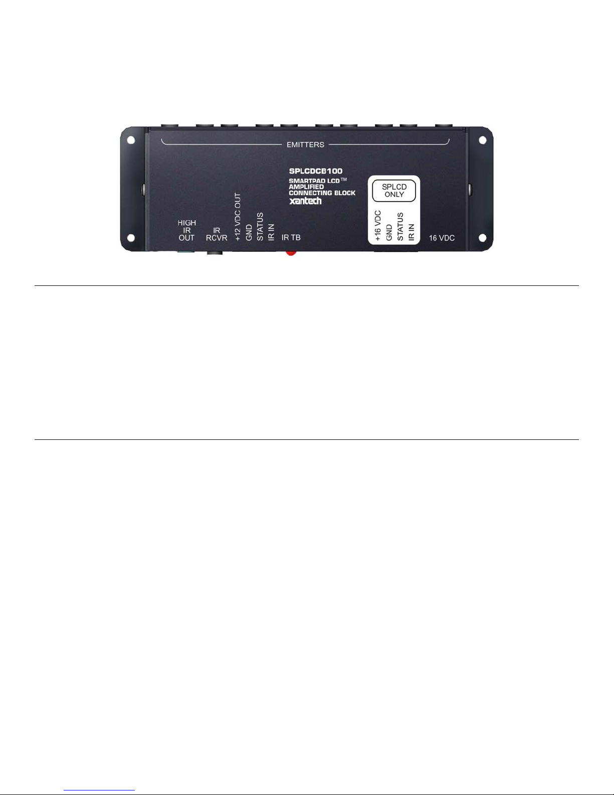
The SPLCDCB100 Connecting Block allows any combination of SmartPad LCD™ panels and standard Xantech IR
Receivers to be connected in parallel while providing 10 Amplified Emitter outputs (expandable to 100 Emitter Outputs).
The SPLCDCB100 allows central 16VDC powering (for SmartPad LCD™ panels) and includes a regulated 12VDC
Voltage output for powering all standard Xantech IR Receivers (such as the 291-90, 490-90, and 780-90 Plasma Series).
This enables all devices to be wired back to the head-end for centralized wiring distribution.
The SPLCDCB100 also features 10 amplified emitter outputs to assure proper emitter signal strength allowing for longer
emitter runs (up to 500ft with 18AWG wire). The SPLCDCB100 emitter output can also be expanded using Xantech’s 79000 Emitter Expansion Block to accommodate any project.
FEATURES:
• Screw-Terminal Connections for Voltage, Status, IR and GND for SmartPad LCD™ Connection
• Built-In 12vDC Regulator for powering Xantech IR Receivers
• 10 Amplified Emitter Outputs for Xantech full line of IR Emitters (282M, 283M, 284M etc..)
• 3.5mm Quick-Connect Jack for easy IR Receiver Input (also screw-terminal connection for IR Receivers)
• High IR OUT for expansion to Xantech 790-00 Connecting Block (Connect up to nine 790-00 for a total of 100-
Emitters)
• IR Talk Back LED for system verification
• Easily mounts to flat wooden, plastic, or metal surfaces using the included screws.
Page 2
Page 2 Model SPLCDCB100
SPECIFICATIONS:
• Power Input: 16VDC (2.1mm Coaxial Jack)
• Power Output: 12VDC (100mA Max)
• SmartPad LCD™ Connection: 4-Screw Terminal (16VDC Pass thru, GND, Status, IR Input)
• IR Receiver Connection: 3.5mm Quick Connect Stereo Mini Jack & 4-Screw Terminal (12VDC output, GND,
STATUS, IR Input)
• Ten IR Emitter Ports (3.5mm Mono Mini Jack)
• High IR Output: 1Amp Current Output for expansion to 790-00 Connecting Block (3.5mm Mono Mini Jack)
• Dimensions: 6-7/8” L x 2-3/4” W x 15/16” H (175mm L x 70mm W x 24mm H)
• SPLCDPS1 16VDC Power Supply (not included) powers one SPLCD and up to four IR Receivers.
• SPLCDPS4 16VDC Power Supply (not included) powers up to four SPLCD’s and up to four IR Receivers.
• Maximum Emitter Output Current: 12mA
INSTALLATION
POWER WIRING:
1. Connect the 16VDC SPLCDPS1 or SPLCDPS4 power supply to the 2.1mm coaxial power input jack (labeled
16VDC).
2. Plug the AC Adaptor into an un-switched AC Outlet.
SPLCD IR WIRING:
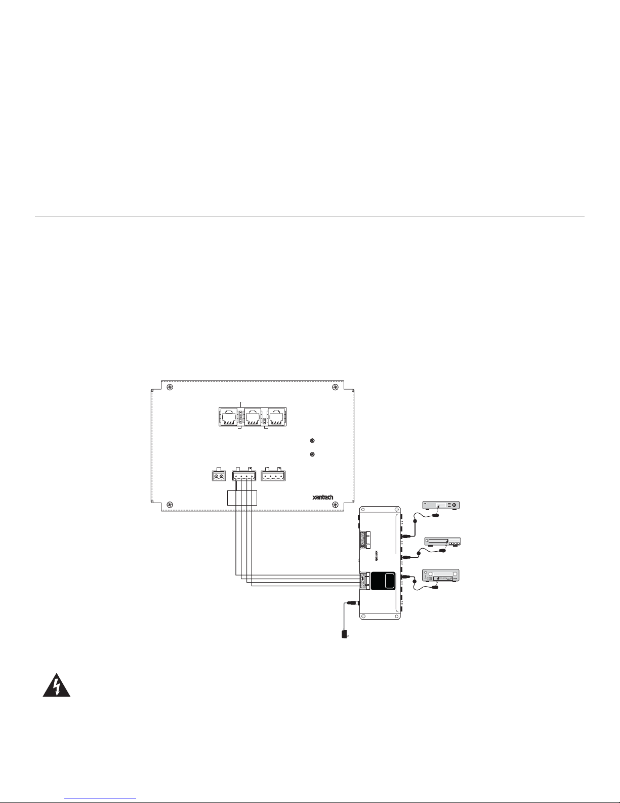
1. Wire 4-Conductor 18AWG from the SPLCD’s IR OUT, GND, STATUS (optional) and +16VDC terminals back to
the appropriate terminals of the SPLCDCB100 Connecting Block. 18AWG can be run in excess of 1000ft. See
Figure 1 for wiring examples.
2. For more than one SPLCD Controller, connect in parallel directly on the 4-screw WECO terminal or use a CB-18
parallel connecting block to neatly combine up to 4-SPLCD controllers (Requires SPLCDPS4 Power Supply).
SPLCD57G
SMARTPAD LCD 5.7
GRAPHIC TOUCHPANEL
TERMINATION
CONTROLLER EXPANSION
SERIAL
+12V IN TO EXPANSION
IR OUT
GND
IR IN
ZONE
CAUTION:
SPLCD ONLY!
DO NOT CONNECT
12V DEVICE
+16V IN ONLY
IR BUS
IR RECEIVER ENABLE
GND
STATUS
IR BUS
+12V OUT
GND
GND
IR IN
IR RECIEVER
EMITTERS
Satellite Receiver
283M
DVD
283M
AV Receiver
283M
Blink-IR
Mouse Emitter
Emitter
Emitter
SPLCD-CB
Amplified Connecting Block
HIGH
OUT
IR
RCVR
IR
+12 VDC OUT
GND
STATUS
IR IN
IR TB
+16 VDC
GND
STATUS
IR IN
16 VDC
SPLCDPS1
16VDC Power Supply
(To Un-Switched AC Outlet)
AMPLIFIED
CONNECTING BLOCK
®
SPLCD-CB
ONLY
SPLCD
Figure 1 – Basic Connection: Connecting the SmartPad LCD™ Controller to the SPLCDCB100
Caution: Remember, the STATUS output can be either an Input (5-30VDC from remote device) to trigger a
Macro within the SPLCD, give LED indication of a Zones power status, or it can be an OUTPUT (+12VDC from
the SPLCD) to trigger some other external device. This is important to note before STATUS wiring is made
between the SPLCD and the other device.
© 2004 Xantech Corporation
Page 3

Model 490-95 Page 3
SPLCD WIRING OVER CAT5:
CAT5 Wire can be used up to approximately 200ft. when wired appropriately (maximum distance may differ
depending upon wiring locations and other outside elements). Follow the appropriate wiring scheme as outlined
below:
1. Twist all four white-stripe wires together on both ends and connect to the GND terminal on both the
SPLCDCB100 and the SPLCD Controller.
2. Twist two solid colored wires together on both ends and connect to the 16VDC terminal on both the
SPLCDCB100 and the SPLCD Controller.
3. Twist the last two solid colored wires together on both ends and connect to terminal labeled IR IN on the
SPLCDCB100 and to the terminal labeled IR BUS on the SPLCD Controller.
Note: If using the STAUTS line, use one of the solid wires in step 3 for STATUS and the other for IR. This will limit
the overall distance to under 200ft.
CAUTION: When using CAT5 always measure the voltage at the rear of the SPLCD across the 16VDC and
GND terminals and confirm the voltage is between 13VDC and 16VDC.
IR RECEIVER WIRING:
1. For IR Receivers with Xantech’s Quick-Connect Stereo Mini Plug, simply plug directly into the 3.5mm IR Receiver
Jack on the SPLCDCB100 connecting block.
2. For all other wiring configurations, connect the 12VDC, GND, STATUS (optional), and IR Output wires to the
appropriate of the SPLCDCB100 Connecting Block.
3. For more than one IR Receiver, connect in parallel directly on the 4-screw WECO terminal or use a CB-18 parallel
connecting block to neatly combine up to 4-IR Receivers.
SPLCD57G
SMARTPAD LCD 5.7
GRAPHIC TOUCHPANEL
CONTROLLER EXPANSION
+12V IN TO EXPANSION
REMOTE ROOM 1
780-90
Plasma-Friendly
J-Box IR Receiver
®
IR
OUT
GND
+12V
REMOTE ROOM 3 REMOTE ROOM 4
490-00
Micro Link
IR Receivers
3-Wire
Cable
+12V
GND
TERMINATION
REMOTE ROOM 2
J-Box IR Receiver
780-90
IR RECEIVER
IR OUT
GND
STATUS
+12V
Series
CFL/LCD Friendly
3-Wire
Cable
Red
Stripe
+12V
IR
OUT
GND
SERIAL
IR RECEIVER ENABLE
780-80
CFL-Friendly
IR
OUT
GND
+12V
480-85
Dinky LinkIR
Receiver
®
Red
(or white)
Stripe
780-80
IR RECEIVER
IR OUT
GND
STATUS
+12V
291-90
Hidden Link
Plasma-Friendly
IR Receiver
Hand Held
Remote
OUT
IR
SPLCD-CB
Amplified Connecting Block
HIGH
OUT
IR
RCVR
IR
+12 VDC O
UT
GND
STATUS
IR IN
SPLCD-CB
AMPLIFIED
CONNECTING BLOCK
IR TB
EMITTERS
®
Satellite Receiver
283M
Emitter
DVD
283M
Emitter
AV Receiver
SPLCD
+16 VDC
ONLY
GND
STATUS
IR IN
16 VDC
283M
Blink-IR
Mouse Emitter
IR OUT
GND
+16V IN ONLY
GND
STATUS
IR IN
ZONE
IR BUS
CAUTION:
SPLCD ONLY!
DO NOT CONNECT
12V DEVICE
Fig. 2 – Advanced Connection: Connecting SmartPad LCD™ and Multiple IR Receivers
© 2004 Xantech Corporation
IR BUS
+12V OUT
GND
GND
IR RECIEVER
IR IN
SPLCDPS1
16VDC Power Supply
(To Un-Switched AC Outlet)
Page 4

Page 4 Model SPLCDCB100
HIGH IR OUT WIRING:
The HIGH IR OUT wiring is for emitter expansion to Xantech’s 790-00 passive Connecting Block. Up to nine 790-00
Connecting Blocks can be combined for a total of 100 emitter ports.
1. Use a Mono Mini cable from the SPLCDCB100 High IR Out connector to either of the two HIGH IR IN/OUT
connectors on the 790-00 Connecting Block.
Note: See the 790-00 Instructions for further details.
CAUTION: The High IR Out jack should only be used when expanding to the 790-00 connecting block. Do Not
Connect Emitters or IR Receivers directly to this jack!
790
Connecting Block
SPLCD-CB
Amplified Connecting Block
SPLCD-CB
AMPLIFIED
CONNECTING BLOCK
STATUS
IR IN
EMITTERS
®
IR TB
SPLCD
ONLY
+16 VDC
GND
STATUS
IR IN
16 VDC
HIGH IR
IN / OUT
EMITTERS
HIGH IR
SIG
GND
GND
790
CONNECTING BLOCK
®
HIGH IR
IN / OUT
HIGH
IR
OUT
IR
RCVR
UT
+12 VDC O
GND
Fig. 3 – Expansion Emitter Wiring: Connecting the SPLCDCB100 to the 790-00
XANTECH CORPORATION
13100 Telfair Avenue, Sylmar CA 91342-3829
phone 818.362.0353 • fax 818.362.9506
Part No. 08905010 Rev B 11-16-04
© 2004 Xantech Corporation
 Loading...