

Page 1
INSTALLATION & PROGRAMMING MANUAL
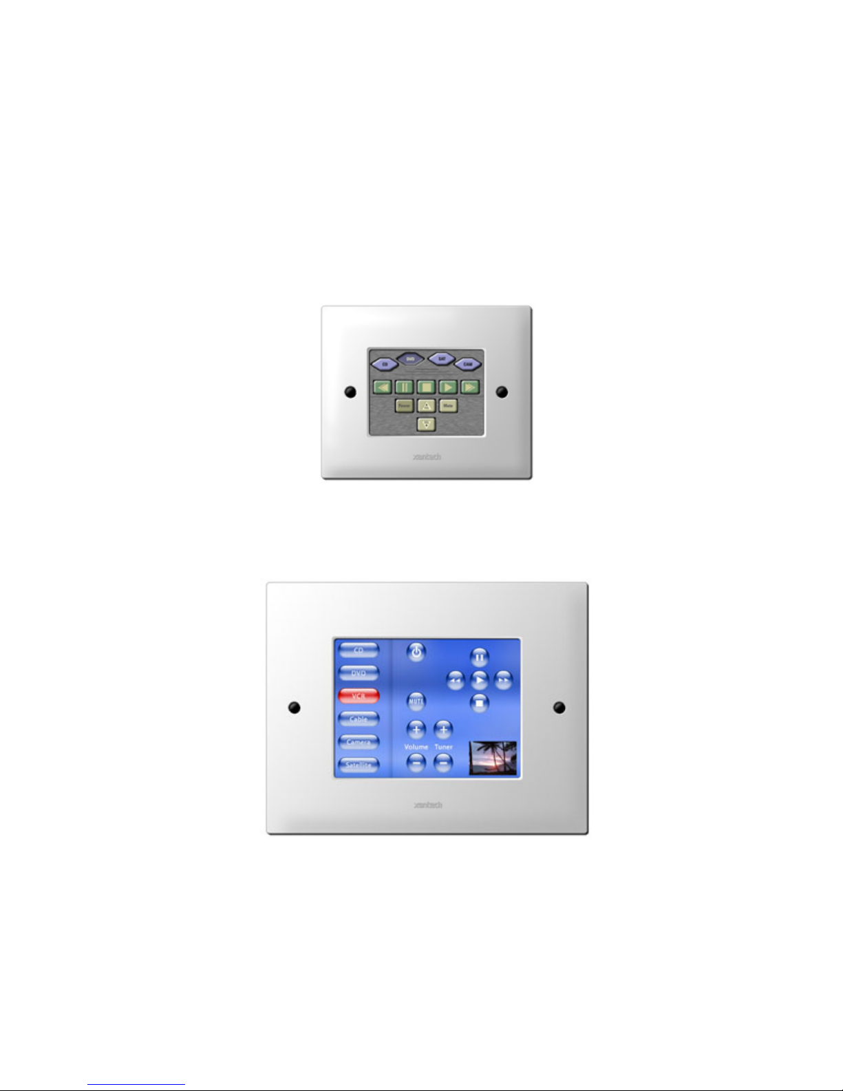
SMARTPAD LCD™
TOUCH-SCREEN PANEL CONTROLLER
Models SPLCD39G, SPLCD64G & SPLCD64V
SPLCD39G
SPLCD64V
Page 2
Page: 2 SmartPad LCD™
SAFETY INSTRUCTIONS - READ BEFORE OPERATING EQUIPMENT
CAUTION: TO REDUCE THE RISK OF ELECTRIC SHOCK,
DO NOT REMOVE COVER (OR BACK)
NO USER-SERVICEABLE PARTS INSIDE
REFER SERVICING TO QUALIFIED SERVICE PERSONNEL
The lightning flash with arrowhead symbol, within an equilateral triangl e, is intended to alert
the user to the presence of un-insulated “dangerous voltage” within the product’s enclosure
that may be of sufficient magnitude to constitute a risk of electric shock to persons.
The exclamation point within an equilateral triangle is intended to alert the user to the
presence of important operating and maintenance (servicing) instructions in the literature
accompanying the appliance.
WARNING
TO REDUCE THE RISK OF FIRE OR ELECTRIC SHOCK, DO NOT EXPOSE
THIS APPLIANCE TO RAIN OR MOISTURE.
This product was designed and manufactured to meet strict quality and safety standards. There a re, however,
some installation and operation precautions, which you should be particularly aware of.
1. Read Instructions – All the safety and operating instructions should be read before the appliance is operated.
2. Retain Instructions – The safety and operating instructions should be retained for future reference.
3. Heed Warnings – All warnings on the appliance and in the operating instructions should be adhered to.
4. Follow Instructions – All operating and use instructions should be followed.
5. Water and Moisture – The appliance should not be used near water – for example, near a bathtub, washbowl, kitchen sink, laundry
tub, in a wet basement, or near a swimming pool, etc.
6. Carts and Stands – The appliance should be used only with a cart or stand that is recommended by the manufacturer. An appliance
and cart combination should be moved with care. Quick stops, excessive force, and uneven surfaces may cause the appliance and
cart combination to overturn.
7. Wall or Ceiling Mounting – The appliance should be mounted to a wall or ceiling only as recommended by the manufacturer.
8. Ventilation – The appliance should be situated so that its location or position does not interfere with its proper ventilation. For
example, the appliance should not be situated on a bed, sofa, rug, or similar surface that may block the ventilation openings; or,
placed in a built-in installation, such as a bookcase or cabinet that may impede the flow of air through the ventilation openings.
9. Heat – The appliance should be situated away from heat sources such as radiators, heat registers, stoves, or other appliances
(including amplifiers) that produce heat.
10. Power Sources – The appliance should be connected to a power supply only of the type described in the operating instructions or as
marked on the appliance.
11. Grounding or Polarization – Precautions should be taken so that the grounding or polarization means of an appliance is not
defeated.
12. Power-Cord Protection – Power- supply cords should be routed so that they are not likely to be walked on or pinched by items
placed upon or against them, paying particular attention to cords at plugs, convenience receptacles, and the point where they exit from
the appliance.
13. Cleaning – The appliance should be cleaned only as recommended by the manufacturer.
14. Power Lines – An outdoor antenna should be located away from the power lines.
15. Nonuse Periods – The power cord of the appliance should be unplugged from the outlet when left unused for a long period of time.
16. Object and Liquid Entry – Care should be taken so that objects do not fall and liquids are not spilled into the enclosure through
openings.
17. Damage Requiring Service – The appliance should be serviced by qualified service personnel when:
A. The Power-supply cord or the plug has been damaged; or
B. Objects have fallen, or liquid has spilled into the appliance; or
C. The appliance has been exposed to rain; or
D. The appliance does not appear to operate normally or exhibits a marked change in performance; or
E. The appliance has been dropped, or the enclosure damaged.
18. Servicing – The user should not attempt to service the appliance beyond that described in the operating instructions. All other
servicing should be referred to qualified service personnel.
19. FCC Notice – This device complies with Part 15 of the FCC Rules. Operation is subject to the following two conditions: (1) this device
may not cause harmful interference, and (2) this device must accept any interference received, including interference that may cause
undesired operation.
© 2008 Xantech Corporation
Page 3

SmartPad LCD™ Page: 3
TABLE OF CONTENTS
SAFETY INSTRUCTIONS - READ BEFORE OPERATING EQUIPMENT ............................ 2
SECTION 1: GENERAL INFORMATION & FEATURES ....................................................... 7
GENERAL INFORMATION ................................................................................................................................ 7
Optional Accessories....................................................................................................................................... 7
SYSTEM OVERVIEW......................................................................................................................................... 8
SMARTPAD LCD FEATURES........................................................................................................................... 9
SMARTPAD LCD PANEL AND FEATURE DESCRIPTIONS......................................................................... 10
SPLCD Front Panel Features and Connections:........................................................................................... 11
SPLCD Rear Panel Features and Connections ............................................................................................ 12
SECTION 2: INSTALLATION & CONNECTIONS ............................................................... 14
INSTALLATION................................................................................................................................................ 14
Back Box Mounting Instructions .................................................................................................................... 14
SPLCD POWER SUPPLY AND INPUT/OUTPUT WIRING INSTRUCTIONS................................................. 16
POWER SUPPLY & STANDARD XANTECH IR OUTPUT BUS WIRING................................................... 16
Power Supply Wiring..................................................................................................................................17
IR Wiring.....................................................................................................................................................17
External IR Input Wiring..............................................................................................................................18
MRC CONTROLLER AND EXPANSION PORT WIRING............................................................................ 19
Controller Terminal.....................................................................................................................................19
Expansion Terminal....................................................................................................................................19
Serial RS422/232 Port Wiring ..................................................................................................................... 20
IR In Zone...................................................................................................................................................21
Installing THE SPLCD INto THE Back-Box................................................................................................ 22
Viewing Angle.............................................................................................................................................22
SECTION 3: MAINTENANCE & CALIBRATION ................................................................. 23
CALIBRATION ................................................................................................................................................. 23
TOUCH SENSE CALIBRATION................................................................................................................... 23
MAINTENANCE................................................................................................................................................ 23
Cleaning......................................................................................................................................................... 23
SECTION 4: PROGRAMMING THE SMARTPAD LCD™ ................................................... 24
INSTALLING AND CONFIGURING THE UNIVERSAL DRAGON™ SOFTWARE ........................................ 24
UNIVERSAL DRAGON™ MINIMUM REQUIREMENTS.............................................................................. 24
Included Hardware & Software Items............................................................................................................ 24
Connecting The SmartPad LCD™ to The PC............................................................................................... 24
DB9 Serial Connection...............................................................................................................................24
USB Serial Connection...............................................................................................................................24
Software Installation ...................................................................................................................................... 25
Starting Universal Dragon Drop-ir™ Software............................................................................................... 25
Serial Port Selection...................................................................................................................................25
Configuring USB Port.................................................................................................................................26
Selecting the Proper Com Port...................................................................................................................26
Verifying COM PORT Communication.......................................................................................................... 26
Who Am I....................................................................................................................................................26
SPLCD FIRMWARE UPGRADE................................................................................................................... 27
Downloading Firmware Files From The Web.............................................................................................27
Upgrading the SPLCD Firmware................................................................................................................27
Firmware Download Interruption................................................................................................................28
GLOBAL PREFERENCES............................................................................................................................ 28
General.......................................................................................................................................................28
© 2008 Xantech Corporation
Page 4

Page: 4 SmartPad LCD™
Serial...........................................................................................................................................................28
SPLCD / XTR39..........................................................................................................................................28
STARTING A NEW SPLCD PROJECT............................................................................................................ 29
Blank Project..................................................................................................................................................29
Default Project (MRC88.................................................................................................................................29
AutoBuild Wizard............................................................................................................................................30
CREATING THE GRAPHICAL USER INTERFACE (GUI) .............................................................................. 33
MANAGING THE WORKSPACE ..................................................................................................................34
Choosing A Style............................................................................................................................................35
Backgrounds...............................................................................................................................................35
Building a Page (Working with GTL’s)...........................................................................................................36
Placing Source GTL’s.................................................................................................................................36
Home Page.................................................................................................................................................36
Placing Function Button GTL’s...................................................................................................................37
EDITING GTL PROPERTIES ........................................................................................................................37
EDIT/GRAPHICS TAB...................................................................................................................................38
Image 1/Image 2.........................................................................................................................................38
Size Image to Text......................................................................................................................................38
Original Size................................................................................................................................................38
BUTTON ........................................................................................................................................................38
Name ..........................................................................................................................................................38
Size.............................................................................................................................................................38
Resizable....................................................................................................................................................38
Locked ........................................................................................................................................................38
Caption On All Images................................................................................................................................39
Bank Tracking.............................................................................................................................................39
Keywords....................................................................................................................................................39
IMAGE............................................................................................................................................................39
Caption........................................................................................................................................................39
Font.............................................................................................................................................................39
INSERTING LABELS ....................................................................................................................................40
INSERTING ADDITIONAL PAGES FOR A SINGLE SOURCE ...................................................................41
Insert a New Page ......................................................................................................................................41
Return to Previous Page.............................................................................................................................41
IMPORTING AND EXPORTING SPLCD PAGES.........................................................................................42
Exporting SPLCD Pages ............................................................................................................................42
Importing SPLCD Pages.............................................................................................................................42
LEARNING IR COMMANDS (CREATING PALETTE FILES) .........................................................................43
Built-In IR Code Library..................................................................................................................................43
TESTING IR COMMANDS IN THE IR LIBRARY..........................................................................................44
IMPORTING XANTECH LEGACY IR PALETTE FILES............................................................................... 45
Learning IR Commands (XIR2) ...................................................................................................................45
Finding the Optimal Positioning of the Teaching Remote ..........................................................................45
Using the Palette Editor..............................................................................................................................46
EDITING FUNCTION NAMES IN THE PALETTE EDITOR..........................................................................47
To Rename an Existing Function................................................................................................................47
To Add a New Function ..............................................................................................................................47
TESTING IR COMMANDS IN THE PALETTE EDITOR ...............................................................................47
IR Command groups....................................................................................................................................47
EDITING Brand, Component, and Function Lists.....................................................................................48
Adding Brands ............................................................................................................................................48
Adding Components and Functions............................................................................................................48
GETTING SOURCE COMMANDS FROM THE INTERNET.........................................................................49
Xantech.com...............................................................................................................................................49
Importing Discrete IR Hex Codes...............................................................................................................49
ENTERING RS232 COMMANDS (CREATING RS232 COMMAND PALETTE FILES).................................. 50
© 2008 Xantech Corporation
Page 5

SmartPad LCD™ Page: 5
ENTERING RS232 COMMAND STRINGS................................................................................................... 51
TESTING RS232 COMMAND STRINGS...................................................................................................... 52
Using PC Test ............................................................................................................................................52
Using SPLCD Test .....................................................................................................................................52
RS232 COMMAND GROUPS....................................................................................................................... 52
PLACING COMMANDS ONTO THE GTL’S (CREATING MACROS) ............................................................ 53
SELECTING IR AND RS232 COMMAND GROUPS FROM THE PALETTE EDITOR................................ 54
Associating Commands To GTL’s (Drag And Drop Commands).................................................................. 54
Auto-Fill IR Commands ..............................................................................................................................54
Manually Associating IR Commands to GTL’s...........................................................................................54
Programming Sequences (Macros)............................................................................................................55
Timed Delays..............................................................................................................................................55
Repeat Commands.....................................................................................................................................55
Delete A Command From the Command List............................................................................................ 56
Testing Commands Placed on the Virtual SPLCD.....................................................................................56
TRANSFERRING THE PROJECT................................................................................................................ 57
SAVING THE PROJECT............................................................................................................................... 57
Save Project...............................................................................................................................................57
Save Project As..........................................................................................................................................57
File Size......................................................................................................................................................57
Project Transfer Interruption....................................................................................................................... 57
SECTION 5: ADVANCED PROGRAMMING ....................................................................... 59
RC68 IR CODE TRIGGERED SEQUENCER .................................................................................................. 59
Programming RC68 Triggered Sequences ................................................................................................... 59
Teaching RC68 Trigger Commands to a Universal Remote......................................................................... 60
Programming the URC-2B/P for Use With SPLCD RC68 Triggered Sequences......................................... 60
RS232 INPUT TRANSLATOR ......................................................................................................................... 61
Programming IR Commands and Sequences............................................................................................... 62
Selecting IR Command Groups from the IR Code Library.........................................................................62
Associating RS232 Commands with IR Commands..................................................................................62
Testing Commands in the RS2322 Input Translator..................................................................................63
SENSE TRIGGER MACROS ........................................................................................................................... 63
Programming The Sense Input...................................................................................................................... 64
INTELLIGENT POWER MANAGEMENT ........................................................................................................ 64
Programming Intelligent Power Management ............................................................................................... 64
ASSIGNING BANK TRACK CODES TO SOURCE GTL’S............................................................................. 65
Programming Bank Track Codes .................................................................................................................. 65
SECTION 6: OPTIONS SETTINGS...................................................................................... 66
RC68 CODE GROUP ....................................................................................................................................... 66
BANK TRACK CODE GROUP ........................................................................................................................ 67
TRACK LED SETTING..................................................................................................................................... 67
LINE INPUT ROLE SETTING .......................................................................................................................... 67
Input............................................................................................................................................................... 68
Output............................................................................................................................................................ 68
BACKLIGHT SETTINGS.................................................................................................................................. 68
DISPLAY ORIENTATION................................................................................................................................. 68
RS232 SETTINGS ............................................................................................................................................ 69
RS232 Port Default Settings.......................................................................................................................... 70
RS232 Port Router Settings .......................................................................................................................... 70
SECTION 7: APPENDIX ...................................................................................................... 71
INTERFACING SPLCD WITH MRC44 (IR CONTROL) & MRC88 (MRC88 EMULATION)............................ 71
MRC88 EMULATION MODE: FEATURE DESCRIPTION & PROGRAMMING ............................................. 71
© 2008 Xantech Corporation
Page 6

Page: 6 SmartPad LCD™
SPLCD/MRC88 EMULATION MODE ...........................................................................................................71
Connecting the SPLCD to the MRC88 Controller.......................................................................................71
Configuring Dragon Drop SPLCD for MRC88 Emulation Mode.................................................................71
Programming SPLCD for MRC88 Functionality .........................................................................................72
Placing MRC88 Objects on the SPLCD......................................................................................................73
MRC88 OBJECT PROGRAMMING: ADDING VOLUME BAR, STATUS BAR ETC… .................................. 74
TRANSPARENT GTL’S AND MRC88 EMULATION....................................................................................74
MRC88 PRESET VOLUME LEVEL PROGRAMMING .................................................................................74
SPLCD / MRC88 PRESET VOLUME LEVEL PROGRAMMING.................................................................. 75
Placing the Volume Bar..............................................................................................................................75
Creating Transparent GTL’s over a Volume Bar........................................................................................75
Assigning the Proper RC68 IR Codes to the Transparent GTL’s...............................................................76
Programming SPLCD for use with MRC44 (Zone Control)......................................................................77
SPLCD 64V VIDEO CONNECTIONS & PROGRAMMING.............................................................................. 79
Checking Firmware Version...........................................................................................................................79
Video Bracket Sub-Assembly.........................................................................................................................80
Video Connections.........................................................................................................................................80
Picture-In-Picture Mode (PiP) ........................................................................................................................80
Enabling Full-Screen Video Mode .................................................................................................................81
Return to PiP Mode........................................................................................................................................81
TRANSPARENT BUTTON OVERLAY: FEATURES & PROGRAMMING...................................................... 81
TRANSPARENT BUTTON GTL OVERLAY FEATURE ............................................................................... 81
Placing Transparent Button GTL’s in Full Screen Video Mode..................................................................81
Transparent Button GTL and Music Server Integration..............................................................................82
CUSTOM BACKGROUNDS AND TRANSPARENT GTL’S.........................................................................83
Importing Pictures as Custom Backgrounds ..............................................................................................83
© 2008 Xantech Corporation
Page 7

SmartPad LCD™ Page: 7
Section 1: General Information & Features
GENERAL INFORMATION
The SmartPad LCD series of Touchpanel Controllers is Xantech’s latest generation of the SmartPad Keypad.
The SmartPad LCD Series consists of three, interactive, touchpanel keypads – a 3.9”, and a 6.4” diagonal color
graphic keypads as well as a 6.4” diagonal video keypad. All functionality and screen graphics are fully
programmable using Xantech’s Universal Dragon™ software. The programming interface is via the RS232 or
USB ports located conveniently behind the detachable faceplate on the front of the unit. All Models come with
an extensive built-in IR Code Library as well as the ability to learn IR codes via the Learning Eye located on
front of the unit.
As with the previous models of SmartPad Keypads, these new touchpanels are designed to be stand-alone
controllers with the ability to output IR commands onto the standard Xantech four-wire IR Bus as well as receive
(and pass-through) IR commands via the built-in IR receiver. These new touchpanels also ha ve the ability to
receive and transmit RS232 commands for a wide range of control options. This keypa d is also directly
compatible with Xantech’s MRC88 products for seamless integration with the Whole-house Audio Video
Entertainment system.
The SmartPad LCD™ Touch-Screen Panel Keypad includes the following components:
• One SmartPad LCD Touch-Screen Panel
• One DB9 RS232 programming cable to connect (Part No. 05913778)
• One USB programming cable (Part No. 05913660)
• One front panel designer Bezel (white)
• Keypad Installation Kit which includes the keypad panel back-box enclosure, an installation template (Part
No. 09590255), 4 back-box mounting clips and touch-panel mounting screws
• CD-ROM Disc contains the Universal Dragon Drop-IR Programming Software (Part No. 03501085-01)
• SmartPad LCD™ Installation & Programming Instructions (Part No. 08901480)
• Two-4 conductor WECO connector plugs (Part No. 05997400)
• One-2 conductor WECO connector plug (Part No. 05996800)
• 4 Keypad jumpers for Zone Termination, Keypad Address and IR Sensor Enable (Part No. 06500135)
Power Supplies (not included, must be purchased separately)
• SPLCDPS1 Powers one SPLCD
• SPLCDPS4 Powers up to four SPLCDs
Optional Accessories
• Optional front panel Designer Bezels:
- Almond
- Black
- Brown
- Ivory
• RS422232 Converter (used for bi-directional RS232 communication between SmartPad L CD and other
RS232 devices
• RS2321X8 Eight Port Serial Router
• External IR Receivers
480 Dinky Link™ Series IR Receivers
490 Micro Link™ Series IR Receivers
780 J-Box Series IR Receiver
291 Hidden Link™ Series IR Receivers
© 2008 Xantech Corporation
Page 8
Page: 8 SmartPad LCD™
SYSTEM OVERVIEW
The SmartPad LCD is a complete control system in a single box – meaning, no extra controller box is
necessary. Simply connecting a power supply and then connecting the SmartPad LCD outputs to any standard
Xantech IR bus, makes a complete IR Repeater System. By adding the optional RS422232 converter, you can
literally control almost any Audio Video or Home Automation component. The SmartPad LCD or SPLCD is also
directly compatible with the MRC-88 Whole-house Audio Video Entertainment System.
SmartPad LCD is easily programmed with Xantech’s Universal Dragon Drop-IR Software via a RS232 or USB
Port (Programming cables and software included). Universal Dragon is used to graphically design your scre ens
and assign IR and/or RS232 Macros. An internal IR Library is also included for ease of programming.
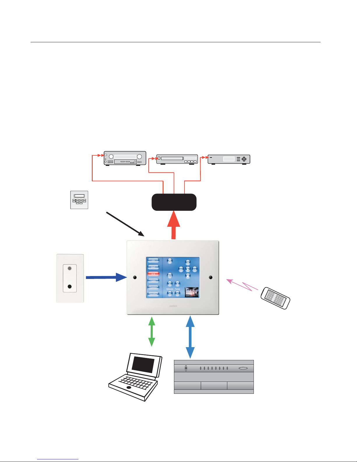
The SmartPad LCD can be wired into numerous simultaneous appli cation configurations such as outlined below
in Figure 1.
Alarm Keypad
AV Receiver
Sense Trigger
Input for Macro
Event Activation
VCR
IR Connecting BlockIR Connecting Block
Satellite Receiver
External IR Bus
Input
Plasma-Friendly
IR Receiver
Bi-Directional
RS422/232 Control
over CAT5
PC, Lighting Control,
HVAC or other RS232
controlled device
Xantech IR Bus
Built In IR
Receiver
Direct RS485
Control of MRC88
over CAT5
MRC88
34
POWER
1
2
5
7
8
6
EIGHT ZONE - EIGHT SOURCE AUDIO/VIDEO CONTROLLER/AMPLIFIER
Hand Held
Remote
Figure 1 - System Block Diagram
© 2008 Xantech Corporation
Page 9

SmartPad LCD™ Page: 9
SMARTPAD LCD FEATURES
LCD Touch Screen Interface: Allows for use of GTL’s (Graphical Touch Links). Colorful graphical
representation of functional buttons for touch control of IR and RS232 controlled devices
Upper and Lower Viewing Angles: Software Programmable for exact viewing placement
Programmable Backlight Control: Selectable Time-Out for LCD backlight
Standard Xantech IR Bus Output: Allows for easy interface to existing IR networks
Internal IR Code Library: Built in IR Code Library. Contains all Major Brand Component IR commands. No
need to ‘learn’ commands.
IR Learning: IR commands can be learned from external hand-held remotes through the SPLCD’s built-in
IR learning eye to add to the SPLCD’s built-in IR code library.
Macros: can be built using IR, RS232, repeat or delay commands and associated with a specific button or
event triggered by a keypad button press, an RC68 IR code, an MRC88 compatible keypad command,
control sense status, or by RS232. Up to 40 IR commands can be issued in a single Macro.
IR Receiver: Broad-band IR Receiver (30kHz-100kHz) for pass through of IR commands from Hand-Held
IR Remotes
Talk Back / Status LED: LED indicates presence of IR and/or programmable STATUS indication of Zone
or other user defined power on/off indicator.
RC68 IR Trigger Sequencer: Trigger IR and/or RS232 Macros via RC68 IR command received at the built-
in IR Receiver
Status Input: Trigger IR and/or RS232 Macros with a voltage between 5-30V DC, 100mA.
Status Output: Send an output voltage to trigger the on/off state of another device or indicator. 12V DC @
100mA.
Serial I/O: RS232 control over an RS422 line for RS232 control of remotely located RS232 controlled
devices (Requires optional RS422232 adapter).
MRC88 Plug-N-Play: Direct connect to standard Keypad Input of MRC88CTL for full zon e control
RS232 Com/USB Com Programming Ports: Communication Programming Ports located on the front
panel of the SPLCD under the bezel, used to program the system using Universal Dragon™ Software
Emitter Output: Local Emitter port on the SPLCD Rear Panel. Output from IR Bus & GND terminals, 12V
DC @100mA. (IR In Zone feature, MRC88 only)
Full Motion Video Input (SPLCD64V only): NTSC/PAL composite video input for PiP or full screen, full
motion video display
Firmware Upgradeable for ‘Future Proof’ Technology: Upgradeable via RS232 Com Port or USB
Programming Port. Firmware upgrades available for easy download by following links within Universal
Dragon Software (www.xantech.com/products/firmware.htm)
© 2008 Xantech Corporation
Page 10
Page: 10 SmartPad LCD™
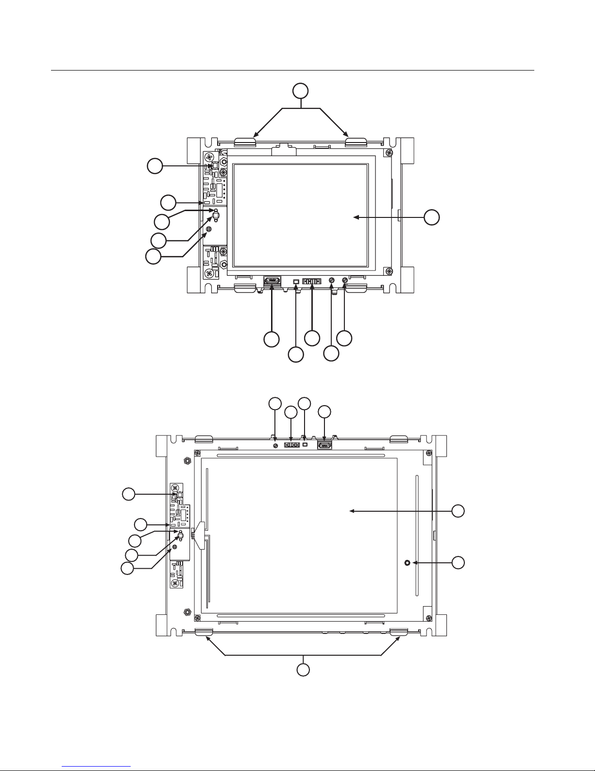
SMARTPAD LCD PANEL AND FEATURE DESCRIPTIONS
12
5
6
3
2
4
1
9
7
8
10
11
Figure 2a – SmartPad LCD™ Model SPLCD39G – Front Panel Features and Functions
10
5
6
3
2
4
8
7
9
1
11
Figure 2b – SmartPad LCD™ Model SPLCD64G & SPLCD64V– Front Panel Features and Functions
12
© 2008 Xantech Corporation
Page 11

SmartPad LCD™ Page: 11
SPLCD FRONT PANEL FEATURES AND CONNECTIONS
1. LCD Touch Screen. Displays Graphical Touch Links (GTL’s ) for touch initiatio n of IR and RS232 Macros.
2. IR Receiver. Receives IR from hand-held remotes to control IR devices connected to the SPLCD and
trigger IR and/or RS232 macros when RC68 IR commands are received. Wide-Bandwidth IR Receiver.
Accepts IR commands with carrier frequencies between 32 kHz and 75 kHz.
3. IR Talkback and Status LED Indicator.
• Flashing LED – Indicates presence of IR at the internal IR receiver or an External IR input.
• Steady Green LED – Indicates Status Line is High, configured either as an Input or Output.
• Blinking LED (During Project Download) – Indicates a Base Unit Transfer is in progress.
NOTE: The IR Talkback LED will also flash, blink or turn on constant when environmental IR light noise
is present.
4. IR Sensitivity Adjustment. Carefully adjust for background light level to prevent false triggering of the IR
circuits. Slowly turn clockwise to reduce sensitivity if positioned as shown in Figures 2a, 2b (Lower
Viewing Angle, with the IR Receiver positioned on the left side), or counterclockwise if installed in the
reverse position, (Upper Viewing Angle, with the IR Receiver positioned on the right side).
5. IR Learning Eye. The IR Learning Eye allows teaching IR Codes to Universal Dragon via the SPLCD when
connected to a PC Com Port (Serial or USB).
6. IR Learning Eye LED. LED brightness indicates the strength of a teaching remote’s output to the SPLCD
IR Learning sensor.
7. RS232 Com Port. 3 Pin Header. Connects the SPLCD to a PC running Universal Dragon Software for
Programming and Firmware Upgrades. (Programming Cable Part No. 03972440)
8. RESET Button. Depressing this button with a blunt object will recycle SPLCD to its initial POWER ON
state.
9. USB Com Port. Connects the SmartPad LCD to a PC running Universal Dragon Software for Programmi ng
and Firmware Upgrades.
10. LCD Backlight Adjustment. Adjusts the brightness of the LCD backlight. Slowly turn counter-clockwise to
reduce brightness.
11. LCD Contrast Control. Adjusts the Contrast of the SPLCD screen. Slowly turn clockwise to increase
contrast.
12. Bezel Mounting Clips (4). Guide clips for mounting the Front Bezel onto the SPLCD.
© 2008 Xantech Corporation
Page 12
Page: 12 SmartPad LCD™
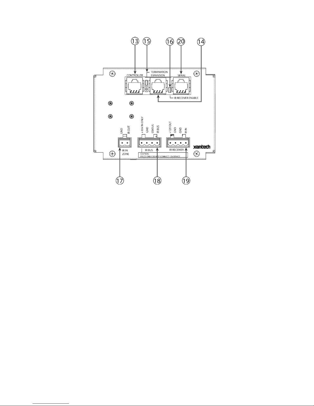
Figure 3 – SmartPad LCD™ – Rear Panel Connections and Functions (Model SPLCD57G Displayed)
SPLCD REAR PANEL FEATURES AND CONNECTIONS
13. Controller Terminal. RJ45 Jack. Connects the SPLCD to a Zone Keypad Terminal on a MRC88 Controller
via CAT5 cable.
14. Expansion Terminal. RJ45 Jack. Allows one SPLCD to be daisy chained to another for multiple control
locations within a zone. Up to 4 SPLCD’s are supported per zone. Can al so be daisy chained to MRC88KP
or MRC88DJKP.
15. Zone Termination. Jumper. Do not remove jumper if there is only one keypad in a zone. If there is more
then one keypad in a zone, remove from all but the last keypad in the daisy chain configuration.
16. IR Receiver Enable. Jumper. Enables the IR sensor on the Keypad. Remove when using an external IR
receiver or if experiencing IR interference from external sources (Plasma, LCD, Fluorescent lights, Sunlight
etc…)
17. IR In-Zone. 2-Terminal WECO style socket - Zone IR out for local ‘In-Zone’ emitter out. Used for IR control
of equipment in the same location as the SPLCD. Output equivalent to that of Xantech Amplified
Connecting blocks. 100mA peak output. Connect directly to Emitter or to Xantech Connecting Blocks (78944 or 791-44). This feature only works with MRC88 and must be enabled in Universal Dragon in the
MRC88 Project/IR Loopback Enabled.
© 2008 Xantech Corporation
Page 13

SmartPad LCD™ Page: 13
18. Power Input & IR Output Terminal:
a. +16VDC: For connection to 16VDC SPLCD Power Supply (Models SPLCDPS1 & SPLCDPS4)
b. GND: Power Supply and IR GND connection
c. STATUS: 5-30VDC, 100mA Status Input for Macro Trigger or LED power Indication from remote
device or 12VDC STATUS output from SPLCD to remote device. (Universal Dragon required to
configure terminal as a Status Input or Status Output).
d. IR BUS Pin: IR Output from SPLCD connects to a Xantech Connecting Block (SPLCDCB100, 789-44,
791-44, CB60 etc.) Can drive a single emitter up to 2000’ on 18AWG.
19. External IR Input. 4-Terminal WECO style socket – Allows connection of other Xantech IR Receivers
and/or Keypads to be used in conjunction with the SPLCD. RC68 commands received here can trigger
internal IR and/or RS232 Macros to be output on the IR BUS Terminal and/or Serial RJ45 Terminal.
20. SERIAL: Bi-directional RS422 Serial Port can be run up to 4000ft (1.2KM) to communicate with a remote
RS232 device (or up to eight RS232 devices using the Xantech RS2321X8). This port connects via
standard CAT5 cable terminated in RJ45 connectors on both ends. The RS42 2232 converter and a 12VDC
Power Supply (both sold separately) are required for RS232 control.
© 2008 Xantech Corporation
Page 14
Page: 14 SmartPad LCD™
Section 2: Installation & Connections
INSTALLATION
BACK BOX MOUNTING INSTRUCTIONS
Each of the four models of SPLCD Touchpanel is mounted in a corresponding junction box (included). No
screws are necessary for affixing this junction box into drywall, lath & plaster, button board or other surfaces
covering a hollow wall. The wall needs to be at least 3.5” (8.9cm) deep, (inside dimensi on).
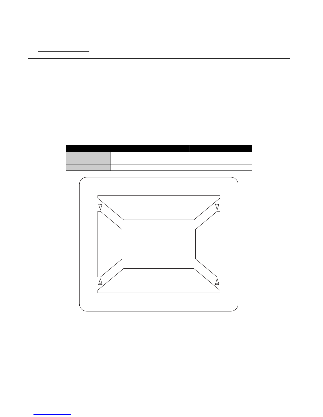
A Mounting Wall-Cutout Template is included for precise hole dimensions. There are two models, one for each
display size (3.9” and 6.4”).
NOTE: The mounting hole size is critical as there is a +0.00” inch tolerance for this cutout. It is imperative that
the provided mounting template be used to assure proper hole size. Check the ta ble below to be sure you are
using the proper Mounting Wall-Cutout Template.
SPLCD Model # Mounting Template Part No. Cutout Dimensions
SPLCD39G 08187158 5.50” X 6.50”
SPLCD64G 08187157 7.63” X 9.49”
SPLCD64V 08187157 7.63” X 9.49”
CUT OUT
CUT
OUT
CUT
OUT
CUT OUT
Figure 4 – Back Box Mounting Wall-Cutout Template
To properly mount the SPLCD, please follow these instructions carefully:
1. Place the Mounting Template on the wall surface as shown in Figure 4 above.
2. Make sure the Template is level and gently secure to the wall using a hammer.
3. Using a hole saw or other cutting tool, carefully cut along the inner guide lines of the Mounting Template
as shown in Figure 5 below.
© 2008 Xantech Corporation
Page 15
SmartPad LCD™ Page: 15
CUTTING TOOL
WALL
CUT-OUT WALL TEMPLATE
Figure 5 – Cutting the Mounting Hole
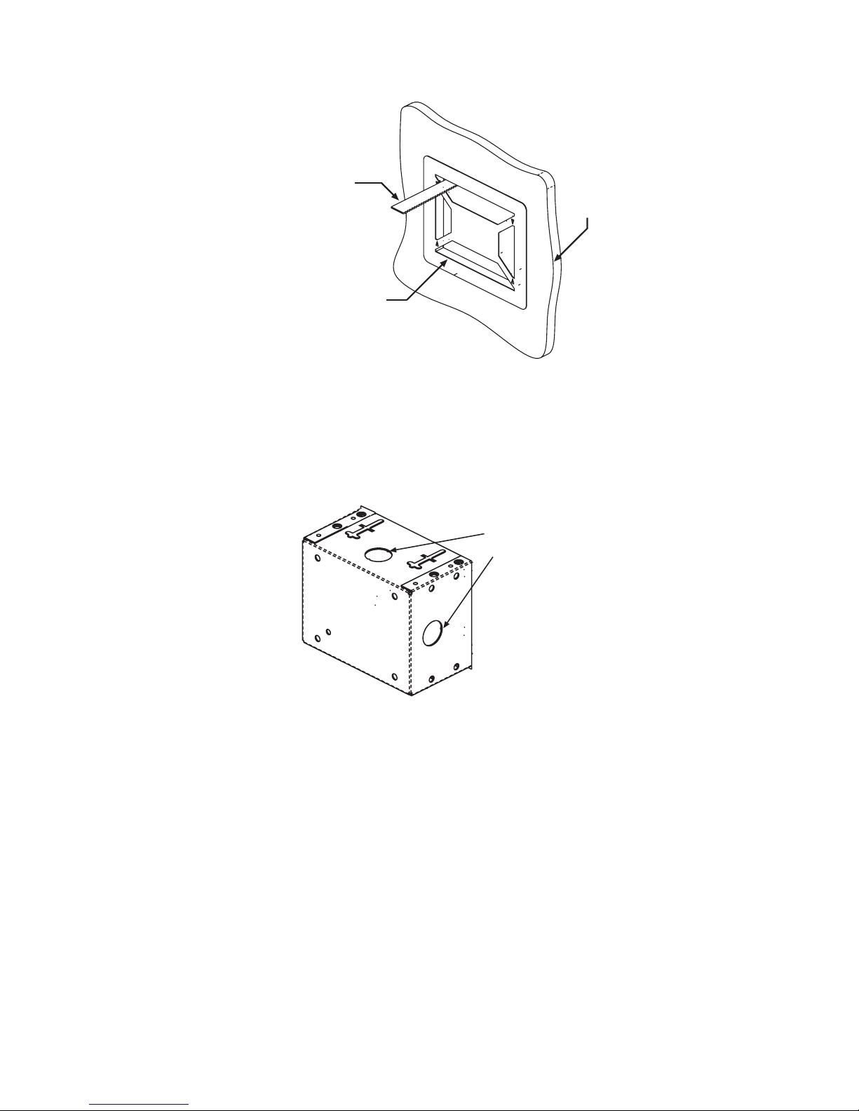
4. After the four areas are cut out, remove the Mounting Template and carefully remove the four areas that
remain attached. Clean the area of any loose pieces. Do not to enlarge the hole past the recommended
dimensions.
5. Remove the appropriate hole-knockouts on the Back Box to allow for wiring of the SPLCD.
Cable Access
Punch-Outs
Figure 6 – Back Box Cable Access Point (Back-Box Rear View)
6. Pull all cables through the wall opening and desired punch-out hole in the Back Box.
© 2008 Xantech Corporation
Page 16
Page: 16 SmartPad LCD™
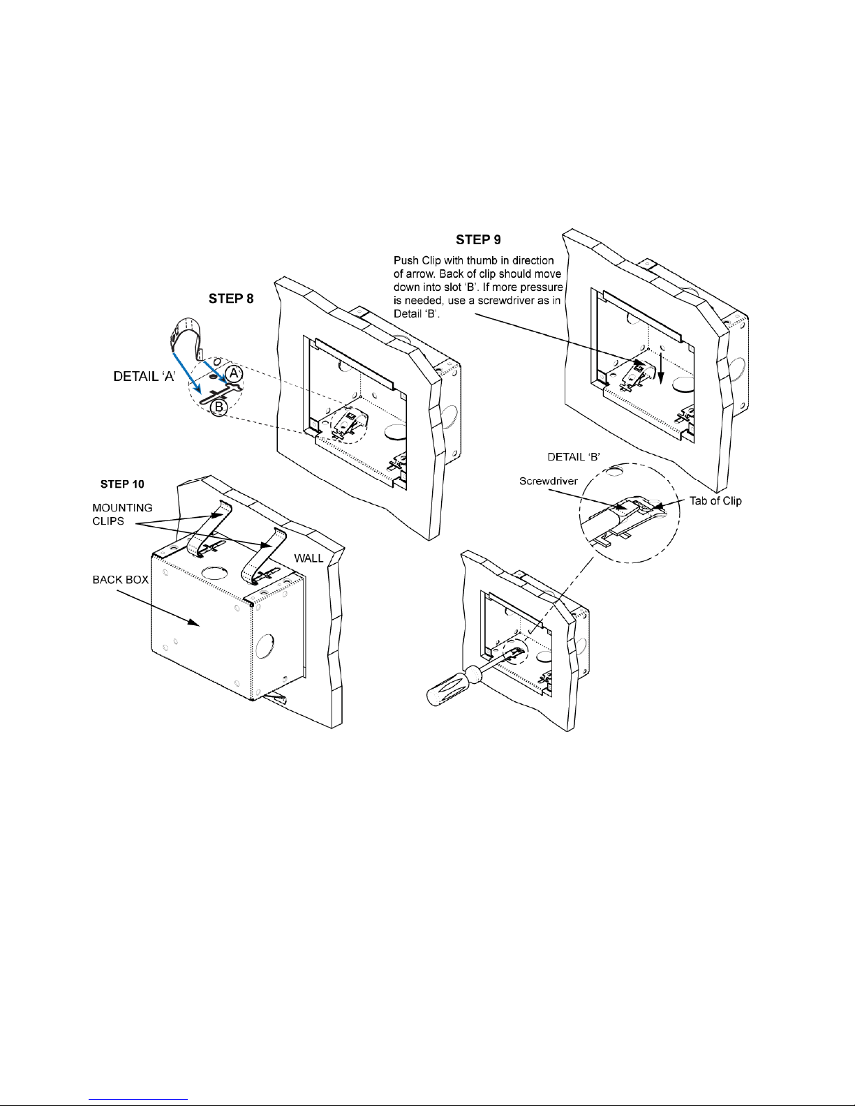
7. Insert the Back Box into the wall and carefully hold it evenly in place as to not allow it to fall into the wall.
8. Insert each Mounting Clip into Slot A while positioning the “T” shape of the Mounting Clip on the inside
surface of the Back Box as shown in Detail A of Figure 7.
9. Push the clip with your thumb in the direction of the arrow. The back of the clip should move down into
Slot B.
NOTE: If more pressure is needed, use a screw driver as shown in Detail B of Figure 7.
10. Repeat Steps 8-9 for all four clips. A rear view of the Back Box with clips installed is shown below.
Figure 7 – Installing Back Box Mounting Clips
SPLCD POWER SUPPLY AND INPUT/OUTPUT WIRING INSTRUCTIONS
The SmartPad LCD can be interfaced in numerous fashions; Standard Xantech IR Bus, RS232, Direct Connect
to MRC88, External IR Input, and Local IR (Emitter Output). The following sections address each of these
wiring configurations.
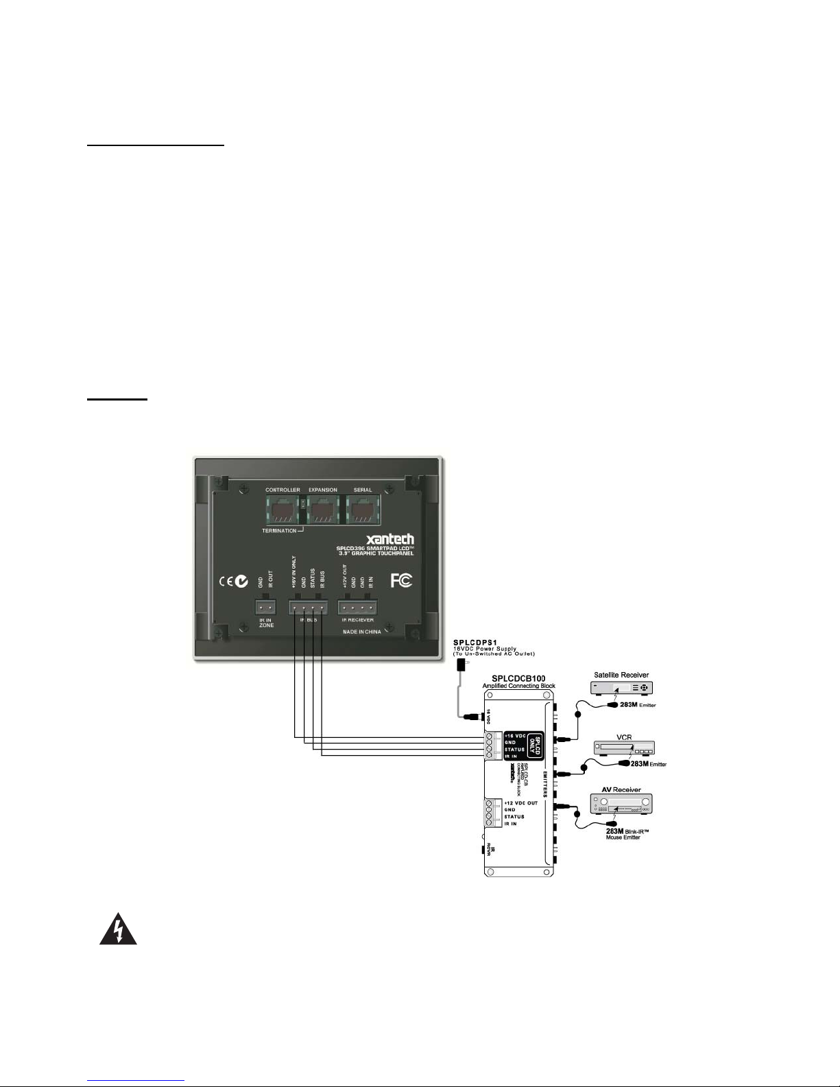
POWER SUPPLY & STANDARD XANTECH IR OUTPUT BUS WIRING
(Figure 3- Item 18)
A 4-terminal WECO connector is provided with the SPLCD for the +16VDC, GND, STATUS, and IR OUT
connections. For convenience of wiring, it is recommended that the Power Supply and IR Connecting Block be
installed at the same location, typically the system head-end, although this is not required. If installed at the
© 2008 Xantech Corporation
Page 17
SmartPad LCD™ Page: 17
head-end, run 4-conductor 18AWG stranded, non-shielded wire to the SPLCD. If multiple SPLCD’s are
being installed pull home-runs from each SPLCD location back to the head-end.
Power Supply Wiring
All models of SPLCD require a 16VDC Power Supply.
• Xantech Model# SPLCDPS1 is a 16VDC Power Supply @ 1.5A that can power for one SPLCD.
• Xantech Model# SPLCDPS4 is a 16V DC Power Supply @ 3.12A that can power up to four SPLCD’s.
Power Supply With a Connecting Block
1. Connect the 2.1mm coaxial plug of the power supply into the 16V DC Input of the SPLCD Connecting
Block (Model# SPLCDCB100).
Power Supply Hard Wired to the SPLCD
1. Cut the 2.1mm coaxial plug off the end of the power supply wire. Spread the two leads and strip
approximately ¼” off the end of each lead.
2. Using the included 4-terminal WECO connector, connect the white stripe lead to the +16V In Only
Terminal and the black wire to GND.
IR Wiring
Connect 4-conductor 18AWG stranded non-shielded wire from the IR BUS, GND, STATUS (optional) and
+16VDC Terminals on the SPLCD to the appropriate terminals on the SPLCDCB100 Connecting Block.
(Figure 8)
Figure 8 – Power Supply and IR Output Wiring (Model # SPLCDCB100 Shown)
Caution: The STATUS Terminal can be either an INPUT (5-30VDC from remote device) to trigger a
Macro within the SPLCD or illuminate the Talkback/Status LED as indication of a unit or zone’s power
status, or it can be an OUTPUT (+12VDC from the SPLCD) to activate an external device. This is
© 2008 Xantech Corporation
Page 18

Page: 18 SmartPad LCD™
important to note before STATUS wiring is made between the SPLCD and the other device. DO NOT
CONNECT AN OUTPUT TO ANOTHER DEVICE’S OUTPUT!
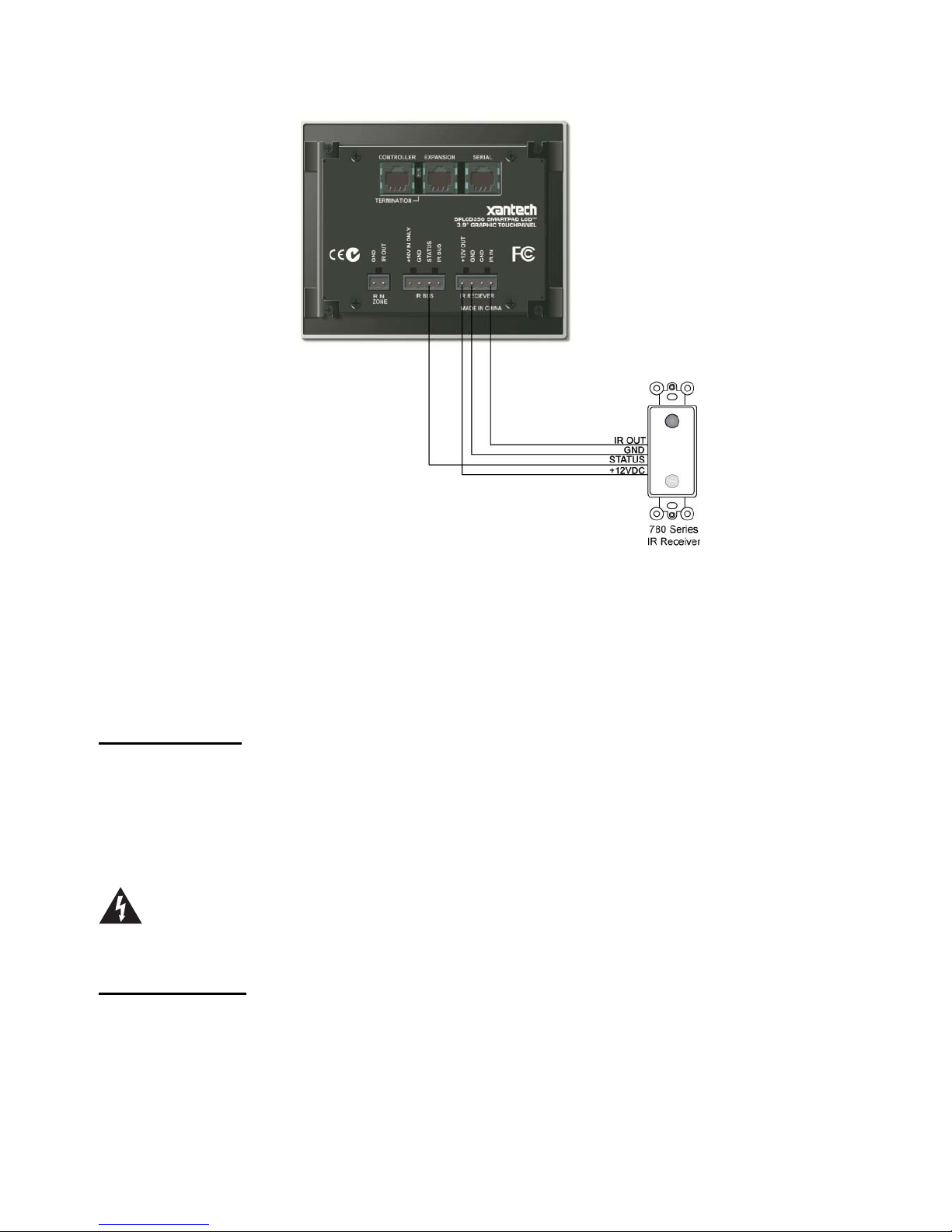
External IR Input Wiring
(Figure 3 – Item 19)
A 4-terminal WECO connector is provided for convenient wiring of external IR Receivers (780, 291, 480, 490
Series) to the SPLCD display. IR commands received here will be rebroadcast and pa ssed out via the Xantech
IR Bus of the SPLCD (Figure 3 – Item 18). RC68 commands received here (of the proper Code Group, C9 set
as default) can trigger internal IR or RS232 Macros programmed into the SPLCD.
• +12VDC Output: This is a voltage regulated +12VDC output signal derived internal to the SPLCD unit from
the 16VDC supply voltage. Use this output to power the external IR Receiver. The 12VDC output can
power a load of up to 100mA maximum (80mA effective load).
Caution: This is a 12VDC OUTPUT only. Do not connect a 12V power source to this point. This is
only an OUTPUT to power an external IR Receiver.
• GND: Both GND Terminals are internally connected to the same point and represent chassis ground of the
unit. Connect either terminal to the GND of the external IR Receiver.
• IR Input: Connect to the IR Output of an IR Receiver such as Xantech 780, 291, 480, 490 Series or other
compatible device.
Pull 3-conductor 18-24AWG stranded non-shielded wire (4-Conductor if using the Status line) from the
SPLCD location to the IR Receiver location. (Figure 9) Wire gauge varies by wire run distance, see table
below:
Length of IR Receiver Wire Gauge of Wire
200’ (61m) 24AWG
600’ (183m) 22AWG
2000’ (610m) 20AWG
5000’ (1524m) 18AWG
© 2008 Xantech Corporation
Page 19
SmartPad LCD™ Page: 19
Figure 9 – External IR Input Wiring
MRC CONTROLLER AND EXPANSION PORT WIRING
(Figure 3 – Items 13/14)
These RJ45 ports are used for interfacing the SPLCD directly to a MRC Controller and/or Expansion MRC
Keypads, (SLPCD’s or MRC88KP’s). The SPLCD can interface to the MRC Products in two ways via this
connection:
1. Via IR along the dedicated IR lines of the CAT5 connected to a MRC44/88 (Pins 4 & 5) (MRC88 & MRC44)
2. Direct to a MRC88 processor via the internal RS485 communication lines (Pins 1, 2 &7).
Controller Terminal
This terminal is used to connect the SPLCD either directly to a MRC88 Controller Zone Keypad Terminal or to
the Expansion Terminal on an existing MRC88 Zone Keypad.
1. Using CAT5 cable terminated at both ends with RJ45 connectors, (EIA/TIA 568B standard) connect the
Zone Keypad Terminal on the MRC88 Rear Panel to the RJ45 connector marked Controller Terminal on
the SPLCD Rear Panel.
NOTE: When the SPLCD is the last keypad connected in line with the MRC88, the Zone Termination
Jumper (Figure 3 – 15) needs to be installed.
Caution: Power voltage for the keypad is transmitted along this cable! Incorrect wiring on this cable
can destroy the MRC Keypad and/or the SPLCD Display! Be sure to test cable for proper
connections before making connections.
Expansion Terminal
This terminal is used to connect the SPLCD to additional SPLCD’s or MRC88 Keypads within a zone.
NOTE: This feature is only functional in a MRC88 System.
1. Using CAT5 cable terminated at both ends with RJ45 connectors, (EIA/TIA 568B standard) connect the
EXPANSION Terminal (Figure 3 – 14) on the SPLCD Rear Panel to the RJ45 Controller Terminal on the
rear of the next SPLCD or MRC88KP in line. (Four keypads max per zone.)
2. Remove the Zone Termination Jumper (Figure 3 – 15) from all but the last keypad in the daisy chain.
© 2008 Xantech Corporation
Page 20
Page: 20 SmartPad LCD™
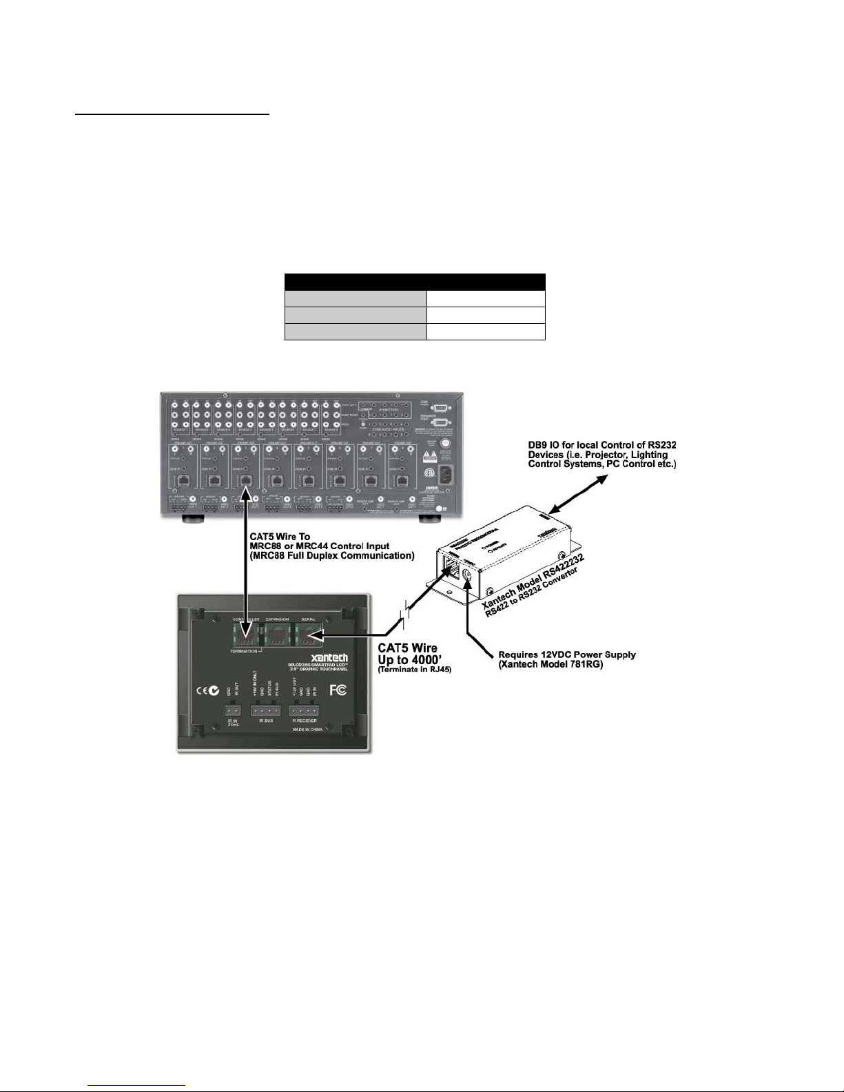
Serial Port Wiring (RS422232)
(Figure 3 – Item 20)
This is a bi-directional RS422 Port that can be run up to 4000ft. (1.2KM) to communicate with a remote RS232
device.
1. Using CAT5 cable terminated in RJ45 connectors in a pin to pin configuration, connect the Serial Port on
the SPLCD Rear Panel to the Serial Port on a Xantech RS422232. (Figure 10)
NOTE 1: The RS422232 Converter (sold separately) and a 12VDC Power Supply (Xantech model
781ERGPS) should be located within 30ft of the RS232 device to be controlled.
NOTE 2: A Null Modem Adaptor may be necessary for proper communication. Please consult
manufacturer’s specification of device being controlled.
DB9 Pin Out Function
2 Rx
3 Tx
5 GND
RS422232 DB9 Pin Out
Figure 10 – Interfacing to MRC and Serial Control
© 2008 Xantech Corporation
Page 21

SmartPad LCD™ Page: 21
IR In Zone
(Figure 3 – Item 17)
IR In Zone allows connection of emitters directly to the SPLCD to control components in the same general area
as the SPLCD.
1. Cut the 3.5mm mini plug off the end of a Xantech IR emitter.
2. Connect the IR OUT Terminal on the SPLCD Rear Panel to the white stripe wire on the emitter wire and
connect the GND Terminal to the black wire on the emitter cable, using the included 2-conductor screw-
type Removable Connector.
3. To control multiple components in the same area, connect these same terminals to an Amplified
Connecting Block (Xantech Model 791-44) using 18-20AWG 2-conductor cable.
NOTE: IR In Zone is a MRC88 feature and must be enabled when programming the MRC88 in Universal
Dragon.
© 2008 Xantech Corporation
Figure 11 – IR In Zone Connections
Page 22

Page: 22 SmartPad LCD™
INSTALLING THE SPLCD INTO THE BACK-BOX
Viewing Angle
The SmartPad LCD™ can be programmed for Upper or Lower viewing angles. The viewing angle the display
was programmed for, affects the orientation of the display in the back box. Displays programmed for Upper
viewing angle need to be installed with the IR Receiver located on the right side and displays programmed for
Lower viewing angle need to be installed with the IR Receiver located on the left side. (Figures 2a & 2b)
1. Pull all wires through the wire-access holes in the Back Box leaving slack for strain-relief and connection
to appropriate terminals on the SPLCD Rear Panel.
2. Insert the SPLCD into the Back Box oriented according to desired viewing angle so that the unit is flush
within the Back Box.
3. Secure with four 6-32x¼” screws (Part No. 103497). NOTE: Do not completely tighten screws.
4. Make sure the SPLCD is level within the box and finish tightening screws. Be sure not to over-tighten.
5. Install front Bezel making sure the two alignment tabs are properly aligned and the Bezel Magnets
‘attach’ to the SPLCD and are holding the Bezel in place. (Figure 12)
6. Push the Bezel gently into the Mounting Clips until it is flush with the wall making sure the side tabs go
through the slots on the metal bracket.
Figure 12 – Installing SPLCD into Back Box
© 2008 Xantech Corporation
Page 23

SmartPad LCD™ Page: 23
Section 3: Maintenance & Calibration
CALIBRATION
TOUCH SENSE CALIBRATION
The accuracy of triggering a Hot-Spot associated to a GTL (Graphical Touch-Lin k ) can be calibrated using a
dull blunt object such as a Stylus from a PDA. The smaller the diameter of the calibration tool, the more
accurate the settings will be, thereby setting the SPLCD to optimum performance.
NOTE: When calibrating a SLPCDG/V, use your finger instead of a stylus.
To enter Calibration Mode:
1. Power ON the SPLCD and allow to boot.
2. With the backlight out, press and hold any area of the Touch Screen display with your finger. If the display
is active (i.e. backlight ON), simply press and hold an area without an active GTL.
3. While keeping contact on the Touch Screen with your finger, gently press & hold the Reset Button
(Figures 2a & b –Item 8) on the display with the stylus.
4. Keep pressure on the screen while the SPLCD is rebooting, approximately 6 seconds, until a white screen
with a black dot appears.
5. Release the screen. The black dot should appear on the same side as the buil t in IR Receiver.
6. With the stylus touch the center of the dot and release.
7. Another calibration dot will appear towards the top middle of the screen. Again, touch the center of the dot
and release. One more calibration dot will appear. Repeat as above. (There a total of three calibration
points).
After touching the third calibration point with the stylus, you can test the accuracy of the calibration. Simply
touch anywhere on the screen and a dot will appear in that touched location. If the dot appears far from the
touch-point location, repeat Steps 2-7.
Exiting Calibration Mode:
After 10 seconds of no activity, the SPLCD
MAINTENANCE
CLEANING
The SPLCD should be cleaned with a non-abrasive cloth such as that used for eye-glass cleaning. No liquid
cleanser should be used directly on the display. If the unit is powered OFF, gently wipe the face of the display
so no fingerprints or dust can be seen.
If the unit is powered ON (active), simply press and hold an area of the SPLCD Display with no active GTL’s.
While holding this area, gently wipe the rest of the display as noted above.
will automatically return to normal operation.
© 2008 Xantech Corporation
Page 24

Page: 24 SmartPad LCD™
Section 4: Programming the SmartPad LCD™
Programming the SmartPad LCD system is a two-step process:
1. Creating the GUI (Graphical User Interface) Screens.
2. Assigning functions (marcos) to the GTL’s (Graphical Touch Links) to control external devices.
Through Universal Dragon™ Software, both of these tasks are easily performed. The software contains a builtin Style Library for creating the GUI Screens as well as a built-in IR-Code Library for programming each of
the GTL’s. This makes programming the SPLCD a very quick and easy process.
INSTALLING AND CONFIGURING THE UNIVERSAL DRAGON™ SOFTWARE
UNIVERSAL DRAGON™ MINIMUM REQUIREMENTS
• Windows 2000/XP/Vista
• 1.5GHz Processor or better
• 512MB Ram (1GB recommended)
• 600MB* Hard drive space (more recommended as projects expand)
• .NET Framework 2.0 (included)
• Mouse, USB, RS232 ports
*600MB = 300 MB Universal Dragon™, 300MB DotNet Framework
INCLUDED HARDWARE & SOFTWARE ITEMS
The Universal Dragon package includes:
• Universal Dragon Drop-IR CD ROM (Part No. 03501085-01)
• DB9 Male to 3 Pin Programming Cable (Part No.03972440). Connects the SPLCD Programming Port
(Figures 2a, 2b – Item 7) to the DB9 COM PORT on your PC.
• USB Programming (Part No.05913660). Connects the SPLCD USB Programming Port (Figures 2a, 2b –
Item 9) to the PC’s USB port.
CONNECTING THE SMARTPAD LCD™ TO THE PC
To program the SmartPad LCD™, the unit must be connected to a PC running Universal Dragon Drop-IR
Programming Software.
DB9 Serial Connection
1. Connect the supplied DB9 Programming Cable (Part No. 03972440) to your PC Serial Port and the other
end to the RS232 Com Port, (3 pin connector located under the bezel on the SPLCD Front Panel) (Figures 2a, 2b - Item 7).
USB Serial Connection
The USB connection requires the included USB ‘A’ Type to USB mini plug cable (Part No. 05913660) to
interface your PC with the USB Com Port on the SPLCD. Connecting a cable to this port will automatically
override any device connected to the RS232 Com Port on the front of the SPLCD.
1. Connect the ‘A’ Type connector (wide end) of the included USB Cable to the PC USB Port and the ‘mini’
Type connector, (small end) to the USB Com Port on the SPLCD Front Panel. (Figures 2a, 2b – Item
9).
NOTE: First time use of a PC for Universal Dragon SPLCD Programming requires t hat certain drivers get
installed to the PC from Universal Dragon. The Install Wizard will try to run as soon as the PC is connected
to the SPLCD. In some cases it maybe necessary to run the Wizard twice. For additional information, see
Section: Configuring USB Port on Page 26.
© 2008 Xantech Corporation
Page 25

SmartPad LCD™ Page: 25
SOFTWARE INSTALLATION
Universal Dragon™ can be installed using the included CD-ROM or as a download from www.xantech.com
.
Given the size of the program, it is recommended that downloading only be done with a high-speed internet
connection. Universal Dragon™ will automatically update when a PC running Universal Dragon™ is powered
up, but it is always a good idea to check the website for the latest version and Application Advisories before
starting a new project. To check for updates to Universal Dragon™, with the PC connected to the internet,
simply click Check For Updates in the Universal Dragon™ Help Menu.
When finished installing Universal Dragon™ double click the shortcut on the pc desktop to launch the program.
Windows 2000/XP/Vista
Install Universal Dragon Drop-IR onto your hard drive as follows:
1. Insert the disc into your computer’s CD-ROM drive. If your drive has been set for auto run, a Xantech
Welcome Menu will appear. If not, access your CD ROM with Windows Explorer and double click the file
"setup.exe".
2. On the Welcome menu, click NEXT.
3. Follow the on-screen instructions as the program installs. Installation time will vary, depending on the speed
of your machine.
STARTING UNIVERSAL DRAGON DROP-IR™ SOFTWARE
After the successful installation of the software, double-click the Universal Dragon™ icon on your desktop o r:
1. From the Pc Start Menu, choose Programs.
2. Select Xantech and click on Universal Dragon™.
3. The program loads and opens to the following Universal Dragon opening screen:
Figure 13 – Universal Dragon Opening Screen
Serial Port Selection
When first launched, Universal Dragon software scans the Serial Ports on your PC and will display the
available ports under Global Preferences in the File Menu. Unavailable ports will not appear.
© 2008 Xantech Corporation
Page 26
Page: 26 SmartPad LCD™
Configuring USB Port
To configure the USB Port for the first time, complete the following instructions:
1. Connect 16V DC to the SPLCD and allow to completely boot.
2. Start the PC and allow to completely boot.
3. Connect the USB Cable from a USB Port on the PC to the USB Com Port on the SPLCD Front Panel
(Figures 2a, 2b – Item 9).
4. A Found New Hardware Window should appear on the PC.
5. Select “Include this Location” when Windows® prompts you for where to look for the driver.
6. Click on Browse and navigate to C:\Program Files\Xantech\Universal Dragon\Drivers. Click OK.
7. In the Install Hardware Wizard Window, click Next, then Finish. If the Install Wizard appears again, repeat
Steps 4-5.
8. Click OK. The PC should now be able to communicate with the SPLCD via USB.
Selecting the Proper Com Port
Normally you would use Com Port 1 (USB will usually appear as COM 3 or above), but if it is already in use, it
will be necessary to use a different one. Select the Com Port as follows:
1. In the File Menu click Global Preferences or simply press CTRL+G on your PC keyboard. The
Preferences Window will appear.
2. In the Preferences Window under Available Ports, select the appropriate Port from the pull-down, then
click OK.
VERIFYING COM PORT COMMUNICATION
Who Am I
Before starting a new project or doing any programming, it is highly recommended that a ‘Who Am I’ procedure
be performed to confirm the firmware version of the SPLCD. This will serve two purposes. One, it will confirm
the connection between the PC and the SPLCD that will be required for all programming; and two, it will assure
that the SPLCD is up to date with all of the latest features and fixes.
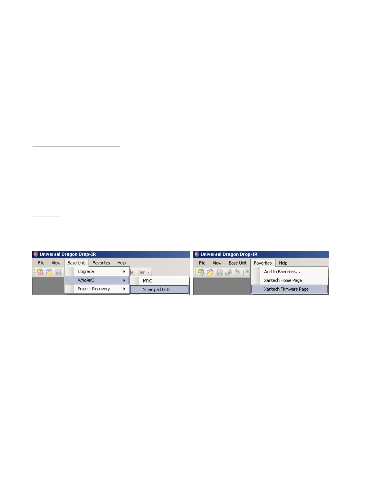
Figure 14 – Who Am I/SPLCD Figure 15 – Firmware Page Link
1. Connect the included DB9 Programming Cable (Xantech P/N 05913778) to a Serial Port on the PC and
to the RS232 COM Port on the SPLCD Front Panel or connect the included USB A-Type to mini USB
plug Cable to a USB Port on the PC and to the USB COM Port on the SPLCD Front Panel.
2. In the Base Unit Menu, select WhoAmI, then SPLCD. The Who Am I? Window will appear with all of the
firmware version information for the SPLCD.
3. In the Favorites Menu, select Xantech Firmware Page. This will load the Xantech Firmware Updates
Page in the web browser.
4. Compare the firmware version from Who Am I? to the version on the Firmware Updates Page. If the
version on the Updates Page has a higher version number, the firmware in the SPLCD should be updated
using the steps in the following section. If the firmware numbers are the same, click OK in the Who Am I?
Window and proceed to section: Starting A New SPLCD Project, (Page 29).
NOTE: If a message is returned stating: ‘Unable to connect to device. Please ensure that your device
is connected.’ this could be due to the following:
1. The SPLCD is not powered ON. Check the power state of the unit.
2. There is a communication error between the PC and the SPLCD. Verify the DB9 or USB cable is
properly connected to the unit and there are no Com Port conflicts
© 2008 Xantech Corporation
in your PC.
Page 27

SmartPad LCD™ Page: 27
3. You have selected the wrong Com Port. Select the proper setting under: File Menu/Global
Preferences.
SPLCD FIRMWARE UPGRADE
The SPLCD has been designed to be “Future Proof”. As product feature improvements are developed, new
System Firmware versions will be made available. Check www.xantech.com
for upgrades when starting a new
SPLCD Project.
Figure 16 – www.xantech.com Firmware Updates Page
Downloading Firmware Files From The Web
1. Open the Universal Dragon™ SPLCD software. Make sure the PC is connected to the Internet and that
the SPLCD is connected to the computer’s COM or USB Port).
2. In the Favorites Menu, select Xantech Firmware Page. This will load the Xantech Firmware Updates
Page in the web browser. This step and the following steps cannot be completed without an Internet
connection.
3. Scroll down until you come to the SPLCD SmartPad LCD Current Firmware Version Box. The most
recent SPLCD firmware update file will be featured here. Click the link to download the most current
Firmware Update. For older versions click on Archived Firmware Versions and scroll to the desired
version (entries are sorted with the newest entries at the top of the list and the oldest at the bottom). Click
on the desired filename link to begin the download process.
4. The File Download Window will appear. Select Save.
5. The Save As Window will open. Navigate to: C:\Program Files\Xantech\Universal Dragon\Firmware.
Click Save.
6. Once the download is complete, click on Close to close the download window. The browser can also be
closed if no longer needed.
Upgrading the SPLCD Firmware
Firmware Upgrades can be conducted to keep the SPLCD up to date and take advantage of new features.
1. Start Universal Dragon™, connect a programming cable to the front of the SPLCD and open a SPLCD
Project. (The SPLCD must be powered up and turned ON.)
2. In the Base Unit Menu, select Upgrade, then SmartPad LCD.
© 2008 Xantech Corporation
Figure 17 – Firmware Upgrade
Page 28

Page: 28 SmartPad LCD™
3. The Open Window will appear. Double-click the firmware file that was just downloaded in Step 5 above to
begin the update process.
4. After the firmware transfer is completed, in the Base Unit Menu, select WhoAmI. The WhoAmI ? Window
will appear and display the three-digit firmware version that was just loaded into the SPLCD. If this is true,
the new firmware has been successfully installed and is ready for use. If not, confirm downloaded firmware
version, connections and try again.
5. If upgrading Firmware to a SPLCD with a Project already loaded, after the upgrade is complete it is
recommended that a Transfer Project be performed to assure that the system project has not been
affected by the firmware upgrade.
Firmware Download Interruption
Once a Firmware Update starts downloading, if it is interrupted at any point during the download, the SPLCD
will possibly lock up and you can lose communication with SPLCD. This can occur when the PC goes into
screen saver or standby power mode, the SPLCD loses power or t he programming cable becomes
disconnected. To restore communication, you can force a firmware upgrade to SPLCD during the first five
seconds after a Reset or Power Cycl e.
1. Make sure the USB/Serial Port is connected from the PC to the SPLCD.
2. Set Universal Dragon up for a firmware upgrade. (Step 2 above.)
3. Before you double-click the firmware file in Universal Dragon (Step 3 above), press and release the
Reset Button on the SPLCD.
4. Within 5 seconds of pressing the Reset Button, double-click the firmware file in Universal Dragon (Step
3 above).
5. The download should begin.
6. If the download does not start, check the PC’s Port Settings to make sure the appropriate Port is selected.
A power cycle of the SPLCD may be necessary if pressing the Reset Button did not allow download.
7. Repeat Steps 4-5 above as appropriate.
GLOBAL PREFERENCES
Before starting programming any projects, it is recommended that these settings be configured. Once set, they
will remain in affect to all Universal Dragon Projects for all models, except as noted, until the settings are
changed.
1. In the File Menu, select Global Preferences. The Preferences Window will appear.
General
If not selected, check the box and set a duration from 1-120 minutes to save AutoRecovery info. This will save
a copy of the project you are working on every ‘X’ minutes. If Dragon crashes you will be presented with the
option to recover to the last saved project.
Serial
Select the appropriate Port from the pull-down, then click OK.
SPLCD / XTR39
If not selected, check the box Warn When Buttons Overlap to have a warning appear when GTL's (Graphic
Touch Links) overlap when creating Graphic Pages.
© 2008 Xantech Corporation
Page 29

SmartPad LCD™ Page: 29
STARTING A NEW SPLCD PROJECT
For example, in this section, a Blank SPLCD 64v Project will be used. With the Universal Dragon software open
and Com Port communication verified, proceed as follows:
Figure 18 – New Project Window
Blank Project
To build a SPLCD Project from scratch, do the following:
1. From the File Menu select New Project (CTL+N) or select Open Project (CTL+O) to modify an existing
project file, or select New Project or Open Project from the Tool Bar. The New Project Window will
appear.
2. Under Project Type, click the ‘+’ next to SmartPad LCD.
3. Select the model SPLCD to be programmed. For example, a 64v will be used.
4. Select the Radio Button for Blank Project. Click OK. A Blank SPLCD Project will open.
NOTE: See: Default Project (MRC88) and AutoBuild Wizard directly below for additional New Project
Options.
5. Resize the SPLCD Window until the full keypad and all tabs are visible (Figure 19).
6. If not selected, click the Graphics Palette and Properties Tabs.
7. Proceed to Section: Creating the Graphical User Interface.
Default Project
(MRC88)
To open pre-configured a SPLCD Project Template for use with an existing MRC88 System, click Default
Project in Step 4 above. Each SPLCD Model features an eight source layout that has been configured for use
with common MRC88 applications and is already setup for MRC88 Emulation. The Button Names (Captions)
can be changed if the Sources and Functions in your system are a little different than the default and these
Default Projects can be modified for any feature or function that can normally be programmed to a SPLCD.
Depending upon the modifications needed to match a Default Project to what you are designing, various
sections of this manual will be helpful in making those changes. Review the Table of Contents for a list of topics
that may apply. The first two sections to review for finishing a Default Project are Sections: Appendix: MRC88
Emulation Mode: Feature Description & Programming and Auto-fill.
© 2008 Xantech Corporation
Page 30

Page: 30 SmartPad LCD™
AutoBuild Wizard
The AutoBuild Wizard allows you to ‘build’ a SPLCD Project, complete with Background, Buttons and IR and/or
RS232 Commands in just minutes. To run the AutoBuild Wizard, proceed as follows:
1. In the File Menu, select New Project or, in the Tool Bar click the New Project Icon.
2. Under Project Type, click the ‘+’ next to SmartPad LCD.
3. Select the model SPLCD to be programmed. For example, a 64v will be used.
Select the Radio Button for AutoBuild Wizard. Click OK. Proceed as follows:
4. The AutoBuild Wizard Start-Up Screen
will appear. Click Next.
6. The Device Select Window will appear.
Select the Device (DVD, Receiver, etc)
for the device being added to the SPLCD
Project from the pull-down. Click Next.
5. The Manufacturer (Brand) Select
Window will appear. Select the Brand for
the device being added to the SPLCD
Project from the pull-down. Click Next.
7. The Graphic Template Select Window
will appear. In the Template File List,
select the device being added to the
SPLCD Project. Click the options for the
Template Files. They will appear in the
Preview Block. Click Next when the
desired Template has been selected.
© 2008 Xantech Corporation
Page 31

SmartPad LCD™ Page: 31
NOTE: Steps 8-9 require that the PC running Universal Dragon is connected to the SPLCD via the COM or
USB Port on the SPLCD Front Panel and that the SPLCD is connected to a Connecting Block with IR
emitters attached to the devices being tested for IR. To test RS232 Commands, the Serial Port on the
SPLCD Rear Panel must be connected to the device via a R422232 Converter. The SPLCD must be
connected to a 16VDC Power supply.
8. The Commands and Codes Window will
appear. A list of available IR, HEX IR and
RS232 Commands will be featured in the
Command Group Block. Select a
Command Group, select Power
ON/OFF from the Commands pull-down
and click the Test Button. If the device
turns ON, you probably have a good
Command Group. Click Next. The
AutoBuild Completed! Window will
appear and setup is complete for this
device. If the device does not respond,
select another Command Group and
repeat Test until a good Group is found. If
no Group works, click the None of the
Codes…Box. Click Next.
9. The Learning Window will appear. IR,
HEX IR and RS232 Commands can be
learned in this window. To learn an IR
Command, in Command Type, select
Learned IR. Select the command in the
list, click Learn and point the original
remote at the Learning Eye on the
SPLCD Front Panel. To learn a HEX IR
Command, in Command Type, select
HEX IR. Select a command and click
Learn. Paste the HEX Code into the popup and click OK. To learn a RS232
Command, in Command Type, select
RS232. Select the command from the list,
click Learn and enter the HEX or ASCII
String into the pop-up and click OK. To
Add a command, click Add and type the
name of the command. To Rename a
command, click the name in the list click
Rename and type the new name. To
Delete a command, select the command
and click Delete. When all Learning is
finished, Click Next.
© 2008 Xantech Corporation
Page 32

Page: 32 SmartPad LCD™
10. The AutoBuild Completed! Window will
appear and setup is complete for this
device. Click Finish.
11. In the Do You Want To Run The
AutoBuild Wizard Again Window, Click
Yes to add more devices. Click No to
Finish. If Yes, repeat Steps 1-10 until all
devices have been added using the
AutoBuild Wizard.
With the preceding steps complete, all sources added using the AutoBuild Wizard will have been placed into
the SPLCD Project in the SPLCD System Window. Click each of the Source Buttons and review the
Function Button layout for each source. The buttons should all be labeled and have IR and/or RS232
Commands associated with each button. The programmed commands will appear in the Macro Command
List.
The Source/Function layouts should be ready to go, but if there are functions that are not required, functions
that need to be added, or additional programming that is required, (Macro Sequences, Trigger Commands, etc)
see the Table of Contents in this Manual for reference to the sections that will guide you through those steps.
If you are satisfied with the results of the AutoBuild Wizard as is, proceed to Sections: Testing Commands
Placed on the Virtual SPLCD and Transferring the Project.
© 2008 Xantech Corporation
Page 33

SmartPad LCD™ Page: 33
CREATING THE GRAPHICAL USER INTERFACE (GUI)
Using Universal Dragon™ software, you can easily create stylish and intuitive screens in multiple pages for
controlling any IR and/or RS232 Device. Once a project is created and a setup environment chosen, you are
automatically placed in Graphics mode and are now ready to create your GUI (Graphical User Interface)
screen.
Figure 19 – SPLCD Graphic Page Edit Screen (Populated)
© 2008 Xantech Corporation
Page 34

Page: 34 SmartPad LCD™
MANAGING THE WORKSPACE
IMPORTANT NOTE: The SPLCD System Window is scalable so the SPLCD System Win dow workspace can
be enlarged for placing and aligning Source and Function Buttons. Clicking the Properties and Project
Overview Auto-Hide Buttons (thumb tacks), sends those windows to the margins. This allows the SPLCD
System Window to be expanded to its greatest size, by dragging the lower right corner diagonally, making the
button placement process much easier. (Figure 20) Rolling over the Project Overview or Properties Tab with
the mouse will cause the Window to pop-up. The Window will automatically ‘hide’ by moving the mouse
anywhere on the screen, clearing the view of the workspace. To keep the window open, for example to add or
edit text on a button, roll over the Properties Tab to un-hide the window, click the Auto-Hide Button again,
and the window will stay in place as originally sized. This is also useful by hiding and unhiding the Project
Overview Tab for direct selection of individual pages without covering the workspace.
Auto-Hide Button position
= Hold. Auto-Hide Button position = Hide.
Figure 20 – Building The GUI Screen
© 2008 Xantech Corporation
Page 35

SmartPad LCD™ Page: 35
Figure 21 – Selecting Background Style Figure 22 – Selecting Source GTL Style
CHOOSING A STYLE
Multiple STYLES of Backgrounds, Source Buttons, and Function Buttons are included in a Graphics
Library within Universal Dragon. Each Style contains its own set of Backgrounds and GTL’s (Graphical
Touch Links). Once a Background is selected, any mix of Source and Function Button Styles will be
available. For purpose of example, a Chromatic Background, with Contemporary Source Buttons and
Skyline Function Buttons will be used.
NOTE: Custom Backgrounds can be imported into Universal Dragon as BMP or PNF Files to create a variety of
special effects. Theme backgrounds can be used to match the personality or interest of the user, a photo image
of an Audio Video Entertainment Center or wall section can be used to create a truly custom control experience.
See Section: Importing Pictures as Custom Backgrounds and Transparent Button Overlay: Features &
Programming for additional information (Page 83).
Backgrounds
Any Background from any Style can be used on a New SPLCD Project. To choose a style:
1. Select the Graphics Tab in the SPLCD System Window. The Graphics Window should now be
displayed in the work environment. Selecting the Graphics Tab will also open the Graphics Palette.
2. In the Graphics Palette, select the Backgrounds Tab. The Background options for a given style will be
displayed in the Graphics Palette, with the Image Attributes of a selected Background indicated directly
below. (Figure 21)
3. Select a Style from the pull-down and browse the associated Backgrounds, Source and Function GTL’s
shown in the list until a desired style is found.
4. Once a suitable style is found, with the Backgrounds Tab selected, click-&-drag (drag-&-drop!) the desired
background onto the SPLCD System Window.
5. If using the same style Background as Source and Function GTL's, proceed to the next section. If using
a different style Source GTL, click the Source Tab then select the Source GTL Style from the pull-down.
© 2008 Xantech Corporation
Page 36

Page: 36 SmartPad LCD™
BUILDING A PAGE (WORKING WITH GTL’S)
A GTL (Graphical Touch Link) is in plain terms, a graphical button that can be pressed to initiate a macro of IR
and/or RS232 commands or to call up a page of additional GTL’s. A Source GTL will always call up a page of
Function GTL’s and can also have a Macro associated with it if so desired. A Function GTL can initiate a
macro, call up an additional page of Function GTL’s, or do both with the same touch of the GTL. (i.e. Creating a
Menu GTL can initiate a macro to call up a menu screen from a DVD player or Media Server to be displayed on
a video monitor, AND call up an additional page on the SPLCD screen containing the Cursor GTL Buttons used
to navigate the DVD Menu.)
NOTE: When programming a SPLCD64v, the Full Screen Video Mode can be modified to display an actual
DVD or Media Server Menu on the SPLCD and overlay Transparent Button GTL’s allowing control of the
actual DVD or Media Server Menu from the SPLCD64v.
Placing Source GTL’s
1. With the Background placed in the System Window, in the Graphics Palette, click the Sources Tab to
display the Source Buttons associated with the selected Background Style. If using a different style
Source GTL, select the Source GTL Style from the pull-down. The Source Button options for a given
Style will be displayed in the Graphics Palette, with the Image Attributes of a selected Source Button
indicated directly below. (Figure 22)
2. In the System Window, click the Grid Icon to activate the GTL Alignment Grid. If desired, (and highly
recommended), also click the Snap-to Grid Icon. This will automatically snap same size/shape buttons into
horizontal and vertical alignment on the grid for a professional look.)
3. Select a desired Source Button (i.e. DVD, SAT, MSRV etc.) and drag-and-drop the Source GTL onto the
Background.
NOTE: If a Source Button with a particular legend (DVD, SAT, etc.) is not shown in the list, select a Blank
Source Button (no lettering on the GTL) and drag it onto the Background. Blank GTL’s can be edited and
customized for text and color. See Section: Editing GTL Properties below for instructions.
4. Once on the Grid, the GTL can be placed anywhere on the screen. To move the GTL either click and drag
to the proper placement, or simply select the GTL with the mouse and then use the arrow keys on the PC
Keyboard to move the GTL to the proper placement.
NOTE: GTL X/Y Coordinates are displayed in the Information Bar at the bottom of the Universal Dragon
Screen. The Snap-to Grid will align same-size/same-shape GTL’s, but when mixing GTL’s of
different
styles, sizes and shapes, it is sometimes more effective to turn the Snap-to function off and use the X/Y
Coordinates for reference in aligning GTL’s. For fine movement of GTL’s, click a GTL and use the arrow
keys on the PC Keyboard.
5. Repeat Steps 3-4 for all Source Buttons.
NOTE: When a Source GTL is placed on the screen, a new Page is automatically inserted for placing
Function GTL’s associated with that Source. Multiple pages can be inserted for a single source as
needed. Individual Pages are shown in the Product Overview Window Tree View. (See Section:
Inserting Pages for additional information.)
Home Page
When placing Function Button GTL’s, it is very important to plan the locations of buttons that will be used on
all pages, such as Volume, Mute and Power. The easiest way to do this is to click the Home Page Icon in the
System Window. This will change what is displayed in the System Window to the top level of the SPLCD
Project showing only Source GTL’s and Function GTL’s that are to appear on all pages. Place these types of
buttons first, and then select a Source and place the specific Function GTL’s for the Source Page being
configured, so you don’t have to go back and rearrange work that has already been done. Page Up and Page
Down will not necessarily appear on all pages, but plan ahead and leave a consistent space on each page for
these important navigation buttons when needed.
NOTE 1: Function GTL’s placed on the Home Page appear on all Pages. Any change to a GTL on the Home
Page will affect that GTL on all Pages. If a particular Function GTL is not to appear on all Pages, do not place
it on the Home Page, rather manually place and position that Function GTL on the desired Pages. Source
GTL’s will always appear on all pages except as indicated in NOTE: 2.
NOTE 2: All Source and Function GTL’s placed on the Home Page are turned off in Full Screen Video Mode
on the SPLCD64v.
© 2008 Xantech Corporation
Page 37
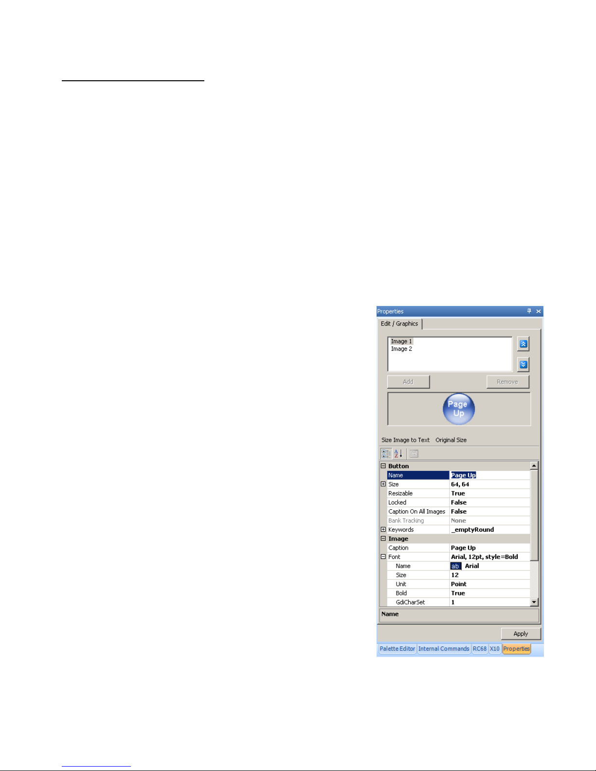
SmartPad LCD™ Page: 37
Placing Function Button GTL’s
Once a Source Page has been inserted, you may now start placing Function Button GTL’s associated with
that Source onto the Source Page.
1. Click on a Source Button located in the SPLCD Systems Window. The Source Button should now
appear selected.
NOTE: GTL’s have an UP and DOWN graphic associated with them. UP depicts the GTL in its nonselected state and the DOWN graphic depicts the GTL in its selected state. The UP and DOWN graphics
will typically be indicated by a difference in color or shading or both. The UP and DOWN graphics can be
edited. See Section: Editing GTL Properties directly following, for additional information.
2. Click the Functions Tab in the Graphics Palette. All of the Function Buttons associated with that Style
will be displayed.
3. Select a Button and drag-and-drop it anywhere on the Background in the SPLCD System Window.
4. If a desired Function Button is not shown in the list, simply select a Blank Button and drag it onto the
Background. As mentioned above, this button can be edited to display the desired text and color you wish.
NOTE: You may also place a Text Label onto the Background to describe the function of a button or group
of buttons. This is useful for Volume and Channel Up/Down controls. See Section: Creating Labels for
additional information.
5. Repeat Steps 3 & 4 for all desired Function Buttons for each Source.
EDITING GTL PROPERTIES
The Properties of a GTL button can be edited for Text, Font and Color.
This allows dragging a blank GTL Button onto the any page and editing
it as needed. This is useful when a button is needed for a special
function or Source that is not included in the Graphics Library. Each
GTL has two states: Up and Down. Each of these states can be edited
separately to give a unique appearance when either selected or nonselected.
To Edit a GTL:
1. If already placed in the System Window, click the GTL to be
edited. To edit a new or blank button, click and drag the button
from the Graphics Palette to the Properties Window and click
Original Size.
NOTE: Text on GTL’s from the Graphics Library cannot be
changed or edited. Use a blank GTL for Source or Function GTL’s
not found in the Library. If a particular Button Style is not available
in the Graphics Library as a blank, please logon to the Xantech
Forum at www.xantech.com/forum/ to post button requests and we
will try to accommodate those requests as part of our ongoing
product development effort.
2. If not already open, rollover the Properties Tab to unhide the
Properties Window and click the Auto-Hide Button (thumb tack)
to hold the window open.
Figure 23 – Button Properties
© 2008 Xantech Corporation
Page 38

Page: 38 SmartPad LCD™
EDIT/GRAPHICS TAB
Use the following tools as needed to modify button graphics and configure text on placed blank buttons:
Image 1/Image 2
These selections show the UP and DOWN views and Button (graphical) and Image (text) Attributes of a
placed GTL (Source or Function; pre-titled or blank). Image 1 selects the UP position; Image 2 selects the
DOWN position.
1. Click Image 1 or Image 2 to select the up or down position for a given button.
Size Image to Text
This tool will reshape a button to fit around text that has been added to a blank button.
1. After all Button and Image Attributes of a button have been set, click to reshape the button to fit the text.
NOTE: This tool will change the shape of the button. To resize the button, in its original shape, to fit the
text, change the Size of the Button.
Original Size
This tool will reshape a button to its original size and shape, whether modified from Size Image to Text or the
Button/Size Settings.
1. Click to return a button to the size/shape it was when originally placed.
BUTTON
The tools in this section adjust the graphical attributes of placed buttons.
Name
This setting allows naming a placed GTL. Pre-configured buttons are already named, but can be re-named (not
recommended), and blank buttons can be named for reference. This setting does not change the appearance of
the Button. It only changes the Button Name in the Attributes
1. Double click to activate the text field.
2. Enter the Button Name (i.e. Page UP)
3. Click Apply. To make changes permanent, in the File Menu, select Save.
Size
This setting allows modifying the size of a placed GTL. Changing the Height and Width can a l so modify the
shape, i.e. change a round button to an oval or a square to a rectangle, etc.
1. Double click on Size or click the ‘-‘ to open the Height and Width boxes.
2. Double click Height or Width or drag the associated value.
3. Enter new size values.
4. Click Apply. To make changes permanent, in the File Menu, select Save.
NOTE: If results are undesirable, re-enter original dimensions or click Original Size.
Resizable
This setting locks the dimensions of a selected GTL so it cannot accidentally be changed. True = resizable;
False = locked.
1. Double click Resizable.
2. Select True/False from the pulldown.
3. Click Apply. To make changes permanent, in the File Menu, select Save.
Locked
This setting will lock a selected GTL in place so it cannot accidentally be moved while configuring the Graphics
Layout of a Page. True = locked; False = movable.
1. Double click Locked.
2. Select True/False from the pulldown.
3. Click Apply. To make changes permanent, in the File Menu, select Save.
© 2008 Xantech Corporation
Page 39

SmartPad LCD™ Page: 39
Caption On All Images
This setting places the same (True) or different (False) Text Attributes on Image 1 and Image 2. This allows
applying different Fonts, Font size, color, weight, etc to create a unique appearance to the UP and DOWN
views.
1. Quickly click twice to change setting or s elect True/False from the pull-down.
2. Click Apply. To make changes permanent, in the File Menu, select Save.
Bank Tracking
This setting will assign a Xantech Bank Tracking Command to a Source GTL as is standard on all Xantech
Keypad Source Buttons. This command will output from the SPLCD when the assigned Source Button is
pressed and change any other Xantech Keypads connected in parallel (IR) or dais y chained (RS485), and
configured with the same Bank Tracking Command to the selected source.
1. Repeatedly click or use the pull-down to select a Bank Tracking Command or None as appropriate.
NOTE: Bank Tracking Commands can only be assigned to Source GTL’s.
2. Click Apply. To make changes permanent, in the File Menu, select Save.
Keywords
Keywords are search tools used by Universal Dragon for the Auto-fill process. Associating ‘Keywords’ to a
button such as Play, Stop, Volume UP, Volume DOWN, Menu UP, Menu DOWN, etc, allows Universal Dragon
to automatically associate specific commands from the Command Groups to Source and Function Buttons
placed on a Source Page in the System Window. (i.e. If Play and Stop buttons have been placed on a Page,
and a Command Group is dragged onto the screen, Universal Dragon will associate the commands titled
Play and Stop with those buttons.)
NOTE 1: When adding or modifying Keywords, be specific. If a button is to be a Volume UP button, be sure the
Keywords include Volume Up and not just Up. Same with Menu Up. This will allow Universal Dragon to fine
tune the search process and better associate the proper commands. (A quick review of the Function Lists
within the Command Groups will help you understand the specific function names associated with the
commands.)
NOTE 2: Keywords added or modified in the Graphics Palette, become universal to all Projects that use that
button. Keywords added or modified in Properties, will only affect that button in that Project.
IMAGE
The tools in this section adjust the Text Attributes of placed buttons.
Caption
This setting enters the text that will appear on a placed GTL.
1. Double click Caption, then enter the text that is to appear on the GTL, in the active text field.
2. Click Apply. To make changes permanent, in the File Menu, select Save.
Font
These settings determine the Font, Font size, weight, etc that will appear on the actual GTL. This is identical to
selecting a font in a word processing program. Typically all fonts loaded to the PC will be available for use in
Universal Dragon.
1. Double click Font, or click the ‘+’ to expand the Font Options List.
2. In the Font line, click the Browse Button to open the Font Window. Make selections from the available
choices and click OK. Or use the individual settings:
Name
1. Continually click Name to scroll through the font options, or select a font from the pull-down.
Size
1. Double click Size, then enter the font size value.
Unit
1. Continually click Unit, or select the font unit of measure from the pull-down.
© 2008 Xantech Corporation
Page 40

Page: 40 SmartPad LCD™
Bold
1. Continually click to select Bold (True) or Normal (False), or select True/False from the pull-down.
Italic
1. Continually click to select Italic (True) or Normal (False), or select True/False from the pull-down.
Strikeout
1. Continually click to select Strikeout (True) or Normal (False), or select True/False from the pulldown.
Underline
1. Continually click to select Underline (True) or Normal (False), or select True/False from the pulldown.
INSERTING LABELS
A Label may be inserted anywhere on the GUI screen to provide a description to a GTL or a group of GTL’s.
(i.e. Volume UP/DOWN).
NOTE: A Label is not programmable for any function. A Button (Text Only) has the same capabilities as a
Function GTL and a Source (Text Only) has the same capabilities as a Source GTL.
Figure 24 – Insert Label
To insert a Label proceed as follows:
1. Right click on any blank area (no GTL’s) in the SPLCD System Window.
2. From the pop-up, select whether this will be a text Label, text-only Source Button, or a text-only Function
Button.
3. Once the Label is placed in the Systems Window, move the Label to its desired location.
4. Right click the Label and select Properties from the drop-down menu to edit the text as outlined in the
previous section.
© 2008 Xantech Corporation
Page 41

SmartPad LCD™ Page: 41
INSERTING ADDITIONAL PAGES FOR A SINGLE SOURCE
Additional blank pages can be inserted as needed, for a given source. After a blank page is inserted, it may be
populated with Function Buttons, as in the previous section. This may be useful when a pag e becomes full of
commands or for easier operation (i.e. placing the Motion Control Buttons and Menu Navigation Buttons of a
DVD Player on separate pages).
A Blank Page is always inserted AFTER the currently selected page.
Insert a New Page
1. Select the Source Button of the desired page (if already on the page to be inserted from, go to Step 2).
2. Drag a blank Function Button onto the existing page to be used as a Go To Page Button. This button will
be used to navigate to the next page.
3. Right-click on the button from Step 2 and select Insert New Page from the pop-up. (Figure 25) While
programming in Universal Dragon, once configured as a ‘Go To’ Button, the button can double clicked to
navigate as configured, i.e. Page Down.
4. A new page is now inserted and may be filled with additional Function Button GTL’s.
5. Additional pages can be inserted in the same manner as needed. If no additional pages are required for the
selected source, place another blank Function Button GTL on the current page. This button will be used
to return (navigate) to the previous page.
Return to Previous Page
6. Drag a Function Button GTL onto the existing page to be used as a Go To Page Button. This button will
be used to return (navigate) to the previous page.
7. Right-click on the button from Step 6 and select Insert Go To Previous Page from the pop-up. (Figure
26) While programming in Universal Dragon, once configured as a ‘Go To’ Button, the button can doubl e
clicked to navigate as configured, i.e. Page Up.
NOTE: This button can also have a macro associated with it to perform a function on the actual Source
Component as well as taking the user to the Next or Previous Page. For example, a MENU button can be
used to call up a menu on the DVD itself and also bring up a page of MENU Cursor buttons on the SPLCD
panel for the User to use to navigate through the DVD Menu.
Figure 25 – Insert New Page Figure 26 – Go To Previous Page
© 2008 Xantech Corporation
Page 42

Page: 42 SmartPad LCD™
IMPORTING AND EXPORTING SPLCD PAGES
Different types of components will sometimes use similar page layouts. That is, device s with Motion Control
(Play, Stop, Pause, etc) use similar button layouts as will Tuning devices for Ch+, Ch-, Numeric entry, etc.
Universal Dragon allows Pages to be ‘copied’ and ‘saved’ (Export) and then reused (Import) for other devices
within a given Project or in a completely separate Project, saving valuable programming time, by not having to
recreate every Page for every device in every Project.
NOTE: A Page Exported with IR or RS232 Commands already programmed will retain that programming. When
the Page is later Imported, it will still have all IR/RS232 programming intact.
Exporting SPLCD Pages
1. In the SPLCD System Window, navigate to the Page to be Exported.
2. Right click in any blank space, (no GTL or PiP) and select Export Page in the pop-up.
3. The Save As Window will appear. Navigate to where you would like to Save Pages. (Creating a New
Folder called Pages within the Projects Folder [C:\Program Files\Xantech\Universal Dragon\Projects] is
convenient for keeping Pages and Projects in one place.) Click Save.
Importing SPLCD Pages
1. In the SPLCD System Window, navigate to where a Page is to be Imported. (i.e. a Source Page with no
Function Buttons.)
2. Right click in any blank space, (no GTL or PiP) and select Import Page in the pop-up.
3. The Open Window will appear. Navigate to where SPLCD Pages have been saved and select the
appropriate Page. The SPLCD Page in the System Window will populate with all graphical GTL’s and
IR/RS232 Commands associated with the Imported Page.
4. If the Background Style of the Imported Page is different than the Background for the rest of the Project
and you want to change it to match the other Pages, click the Graphics Palette Tab. In the Graphics
Palette Window, click the Backgrounds Tab and select the Background Style that matches the other
Pages in the current Project.
5. Click and Drag the Background onto the Imported Page. The Background will change to match the other
Pages in the Project.
6. To change the Button Style on the Imported Page, repeat Steps 4-5, this time selecting the Functions
Tab instead of Backgrounds.
© 2008 Xantech Corporation
Page 43

SmartPad LCD™ Page: 43
LEARNING IR COMMANDS (Creating Palette Files)
IR Codes from the manufacturer’s remotes for each of the components you wish to control from the SPLCD can
be learned into the Universal Dragon™ software and stored in Palette Files (Command Groups) for
placement onto the Keypads. In order to do this, the SPLCD must be connected to the PC as outlined in the
Section: Connecting the SPLCD to the PC.
NOTE 1: Before starting this section, included in Universal Dragon™, is an extensive IR Code Library. Before
learning any IR commands, check the IR Library to see if the IR Commands for the components you wish to
control are listed.
NOTE 2: If you have previously created Palette Files in any other versions of Dragon Drop-IR™ Software (for
programming URC-2’s, MRC88, etc) these files can Imported into Universal Dragon. If all of your codes are
either located in the IR Code Library or are already learned in Command Groups, proceed to the section
entitled: Placing Commands onto the GTL’s.
Figure 27 – Open Palette Editor
BUILT-IN IR CODE LIBRARY
Universal Dragon has a built-in IR Code Library. The IR Code Library is a large database of manufacturer’s IR
Commands for a whole assortment of brands and components. If your manufacturer’s codes are in our
database there might not be any need to ‘teach’ IR commands into the system. To check the Universal
Dragon’s extensive IR Code Library, do the following:
1. Open a SPLCD Project.
2. If not already open, in the View Menu, select Palette Editor or roll over the Palette Tab and click the
Auto-Hide Button (thumb tack) to hold the window open. The Palette Editor will open. (Figure 28).
3. Select Show IR Library.
4. Click the ‘+’ next to the appropriate Brand (Pioneer, Sony, etc). A list of available components will open.
5. Click the Component Type (i.e. VCR, DVD etc). A list of Command Groups for the selected
brand/component’s IR codes (and RS232 commands) will be displa yed.
NOTE: A Tab appear in the margin next to the Palette Editor for each Command Group opened to allow
switching between multiple Command Groups while programming buttons. Use the arrows at the bottom
of the window to scroll through multiple Tabs and use the ‘X’ Button to close unneeded Command
Groups.
6. You will need to test the commands from these different Command Groups to see which one works with
your component. Please see the next section: Testing IR Commands in the IR Library.
© 2008 Xantech Corporation
Page 44

Page: 44 SmartPad LCD™
Figure 28 – Palette Editor
TESTING IR COMMANDS IN THE IR LIBRARY
Once you have located all of the Command Groups for a specific manufacturer/component, you will need to
test the commands to see which Command Group is associated with your specific component.
NOTE: To test commands out of the Library, the PC running Universal Dragon must be connected to the
SPLCD via the RS232 or USB Programming Port and the IR output of the SPLCD must be connected to a
Connecting Block as shown in Figure 8, Page 17. Connect an IR Emitter to the connecting block and attach
it to the component being tested over the IR Eye.
1. With the IR Library opened to the specific manufacturer/component list of Command Groups as outlined
above, click on the first Command Group listed [i.e. 1 (32)]. A list of all of commands associated with this
component will be displayed.
2. With the PC connected to the SPLCD Programming Port, select the Test Button located at the top of the
Palette Editor Window. The Test Button should now be highlighted in dark blue.
3. Click the Power ON/OFF command and other basic function commands as listed in the Command Group.
The controlled component should respond to each command sent. (i.e. Power should turn the source ON
or OFF, Play plays the content etc.)
NOTE: Whenever possible, look for Command Groups with discreet ON/OFF Codes. These will help keep
components in sync with the system by providing absolute power commands.
4. If a component does not respond to a command, click on another Command Group listed for that
manufacturer/component and retest.
© 2008 Xantech Corporation
Page 45

SmartPad LCD™ Page: 45
5. If the codes for the specified component are found in the IR Library, you are now ready to start creating
IR Macros under the GTL Buttons you created in the previous section. Proceed to Section: Placing
Commands onto the GTL’s. If no working commands can be found in the IR Library, proceed to the
Section: Learning IR Commands, Page 45.
IMPORTING XANTECH LEGACY IR PALETTE FILES
If you have worked with previous versions of Xantech Dragon Drop-IR Programming Software, the IR Palette
Files (.pal and .bci) can be imported into Universal Dragon for IR programming when the command files are not
found in the Universal Dragon IR Library.
1. In the Palette Editor, click the Import Icon. (
) The Open Window will appear.
2. In the Open Window, browse to where the Legacy Files are saved, typically: C:\Program
Files\Xantech\Dragon\Palettes
3. Select the Type of File.
4. Click the File to be imported. The Import Palette Window will appear. When the download is complete,
click OK.
5. In the Palette Editor, navigate the Brand List to the appropriate Brand (i.e. JVC). Click the appropriate
type of component (i.e. VCR).
6. The imported commands will be listed as a Command Group. Click the Command Group. The IR
Commands will be listed in the right side window in the Palette Editor and are ready for button
programming.
LEARNING IR COMMANDS (XIR2)
An IR Learning Eye is located on the front panel of the SPLCD and is accessible when the Bezel is removed
(Figures 2a, 2b Item 5).
NOTE: Commands learned through the SPLCD’s front panel learning eye (XIR2 method) are NOT
backwards compatible to some other Xantech devices (i.e. MRC44, URC-2 etc…). This means, palettes
created in Universal Dragon SPLCD cannot be copied to previous versions of Universal Dragon
software.
NOTE: When learning IR commands through the front panel learning-eye, it is suggested that the environment
be free of any IR interference. This could include fluorescent or halogen lighting, sunlight, plasma or LCD
displays and interference from a PC Monitor display.
Finding the Optimal Positioning of the Teaching Remote
An IR strength indicator LED is located on the front panel (IR Learning Eye LED, Figures 2a, 2b - Item 6 Page
10), to show the optimal position for the teaching remote. Before proceeding, position the teaching remote
approximately 1-2 inches from the IR Learning Eye, press any button on the remote and observe the
brightness of the LED. Move the remote slowly up and down past the IR Learning Eye to find the position
where the LED is brightest. This will be the position to be used for recording IR commands.
© 2008 Xantech Corporation
Page 46

Page: 46 SmartPad LCD™
Figure 29 – Learning IR Commands
Using the Palette Editor
NOTE: The Palette Editor for IR Commands is available whether a project is opened or not.
1. If not already open, in the View Menu, click Palette Editor or hit [CTRL+ALT+P] on your keyboard. The
Palette Editor will open.
2. In the Palette Editor, change Mode to Edit, using the pull-down.
3. In the Palette Editor, change Learning Device to SPLCD, using the pull-down.
4. Be sure Test and Show IR Library are de-selected, (normal background).
5. Scroll the Brand List and click the ‘+’ next to the appropriate Brand as shown in Figure 29 (Toshiba). A
sub-directory of components will appear. (If a particular Brand does not appear on the List, see Section:
Editing Brand, Component and Function Lists/Adding Brands.)
6. Click the ‘+’ next to the appropriate Component (DVD). (If a particular Component does not appear in the
sub-directory, see Section: Editing Brand, Component and Function Lists/Adding Components and
Functions.)
7. A Function List for the selected component will appear. Review the Function List and compare it to the
source remote. If a particular function is not displayed or not named appropriately, see Section Editing
Brand, Component and Function Lists/Adding Components and Functions.)
8. Click REC at the top of the Palette Editor. It will highlight to indicate REC Mode. Universal Dragon is now
ready to learn the IR codes for the specific brand/component selected.
NOTE: Before performing Step 9, read Steps 9-12, as the RECORD process is a timed function. You
will have 5 seconds to perform the process before the system times out.
9. Place the Teaching
(source) remote in the optimal position as found above.
10. Select the command to be learned, in the Function List. (i.e. Power, Play, Stop etc.). The Learn IR
Window will appear. You will have approximately 5 seconds to learn the IR command.
11. While holding the source remote in the optimal teaching position, typically within 1-2” of the IR Learning
Eye, press and hold the corresponding command button on the source remote. When the message IR
Learning was successful appears, click OK. An XIR2 Symbol (
) will appear to the left of the selected
function indicating that an IR code has been learned.
NOTE 1: If you wait longer than five seconds, a time-out message: ‘Failed To Learn IR Timeout’ will
appear. Click OK and try again. If you continue to have problems learning commands, run a Who Am I to
confirm PC connection to and communication with the SPLCD.
NOTE 2: When teaching commands, press and hold the button until the IR Learning was successful
message appears. Not all IR codes are structured the same. Some will be learned with a press and hold
while others may require a quick tap of the original remote button. Some will require a button press duration
somewhere in between.
12. Repeat Steps 9-12 for all source functions not found in the IR Library, that are to be used on the SPLCD.
13. All learned commands can now be utilized for programming. In Palette Editor, change Mode to Palette,
select Show IR Library and navigate the Brand/Component List to the learned commands.
© 2008 Xantech Corporation
Page 47

SmartPad LCD™ Page: 47
EDITING FUNCTION NAMES IN THE PALETTE EDITOR
If a function on the Source Remote is not displayed in the Function List, you can either Rename an existing
function or Add a new function to the List. Editing Function Names in the Palette Editor will only affect the
specific Brand/Component Palette File you are currently saving to. (i.e. Making a change to a function under
DENON DVD will only appear in DENON DVD).
To Rename an Existing Function
1. Right-click on the function to be renamed.
2. Select Rename from the pop-up.
3. Edit the text as desired and press Enter on your keyboard.
4. The Rename Window will appear with a Warning Message. Click YES to Save.
To Add a New Function
1. Scroll down to the bottom of the Function List on the right side window of the Palette Editor.
2. Right click on a blank area of the List and select New Command from the pop-up.
3. Enter the name of the new function as you would like it to appear in the List and press Enter on your
keyboard to Save.
TESTING IR COMMANDS IN THE PALETTE EDITOR
Before programming any SPLCD Buttons with learned commands, they should be tested to assure that the
learned commands are the correct commands and that they are functional. The wrong command or a n onfunctioning command in a power or source select sequence will cause system control errors. It is much easier
to find these types of errors by testing newly learned commands, than to try to isolate the problem later.
NOTE: To test learned commands, the PC running Universal Dragon must be connected to the SPLCD via
the RS232 or USB Programming Port. The IR output of the SPLCD should be connected to a Connecting
Block as shown in Figure 8, Page 17. Connect an IR Emitter to the connecting block and attach it to the
component being tested, over the IR Eye.
1. With the PC connected to the SPLCD Programming Port, select Test in the Palette Editor Window. The
TEST Button should now be highlighted.
2. Click on each of the command names one-by-one that need to be tested. The SPLCD screen will display a
test screen for a second or two.
3. The controlled component should respond to each command sent. (i.e. “Power” turns the source ON or
OFF, “PLAY” plays the content etc.)
NOTE: Only functions with a XIR1 (
) or XIR2 Symbol ( ) will execute. IR Commands from the IR
Library will not appear in Edit Test Mode. To test IR Commands from the IR Library, change the Palette
Editor Mode to Palette.
4. If a component does not respond to a command, re-learn and re-test the IR command until the component
responds.
5. Repeat Steps 1-6 for all commands to be tested.
IR COMMAND GROUPS
Unlike previous versions of Dragon Drop-IR, it is not necessary to create IR Palettes from learned commands.
Universal Dragon does this automatically. Learned IR Commands are placed into Command Groups that can
be accessed by clicking Show IR Library in the Palette Editor. The Learned Commands will appear in the
Brand/Component List just as the Library Commands do. The Learned Commands will be listed
numerically in the sub-directory, but will not have an associated numeric code group suffix in parenthesis.
(Figure 30) Learned Commands can also be differentiated from Library Commands by the IR Code Symbol
next to each Function. An IR Library Command will have a
have a XIR1
or XIR2 Symbol just to the left of the Function Name in the Function List.
Symbol and a Learned IR Command will
NOTE: The XIR1 Symbol features a red ‘1’ and the XIR2 Symbol features a red ‘2’.
© 2008 Xantech Corporation
Page 48

Page: 48 SmartPad LCD™
Figure 30 – Learned IR Command Group Figure 31 – Library IR Command Group
EDITING BRAND, COMPONENT, AND FUNCTION LISTS
If a brand, component, or function is not found in the Palette Editor, each can be added as follows:
Figure 32 – Add Brand Figure 33 – Add Component
Adding Brands
1. In the Palette Editor, click Mode and select Edit.
2. Click the Add Menu and select Brand, or right click anywhere in the Brands List and select New Brand in
the pop-up.
3. A Text Box (New Brand) will appear at the bottom of the Brands List. Type the name of the new brand
and press Enter on the keyboard.
4. The new name is added to the list and saved.
NOTE: The New Brand will ultimately be saved to the IR Library Brands List alphabetically, but will not
appear as an IR Library Brand until at least one Component and one Function have been programmed.
To find a New Brand that does not have any commands programmed, in Palette Editor, change Mode to:
Edit and scroll the list to the New Brand.
Adding Components and Functions
1. If not already selected, in the Palette Editor, click Mode and select Edit.
2. In the Brands List, select the Brand to which the New Component is to be added.
3. Click the Add Menu and select Component, or right click the selected Brand then select Add Component
in the pop-up.
4. A Text Box (New Component) will appear at the bottom of the selected Brand’s Components subdirectory. Type the name of the New Component and press Enter on the keyboard.
5. To add Functions (commands), right click in the Command List (right hand column of Palette Editor) and
select Add Command from the pop-up.
6. Type the name of the New Command and press Enter on the keyboard. The new command will be saved
to the Command List and will be available for programming HEX, RS232 or IR Commands for the specific
© 2008 Xantech Corporation
Page 49

SmartPad LCD™ Page: 49
brand/component to which that command is associated. The Function (command) will not appear on any
other brand/component list.
GETTING SOURCE COMMANDS FROM THE INTERNET
Xantech.com
One Internet source for commands is the Xantech Web Site. The XIST (Xantech Integrated System
Technology) Code Library provides an extensive resource of RS232 Commands that are formatted speci f ically
for use with Universal Dragon. The XIST Command and Documentation Matrix includes the RS232
Command Groups, in addition to manufacturer documentation for protocol and connectivity. To download
RS232 Commands from the XIST Code Library:
1. Via the Internet, navigate to www.xantech.com
or with Universal Dragon running, in the Favorites Menu,
click Xantech Home Page.
2. On the Xantech Home Page, click Products.
3. On the Xantech Products Page click Software.
4. On the Software Page under Support Documents, click Xantech XIST Code Library. The XIST
Command and Documentation Matrix will appear.
5. Scroll the list until you find the link for the Command Group for the Brand/Component to be controlled.
6. The File Download Window will appear. Click Save.
7. Navigate to a location that will be easy to remember such as: C:\Program Files\Xantech\Universal
Dragon vX.X\Palettes. Click Save.
8. In Universal Dragon, in the Palette Editor, click the Import Icon (
). The Open Window will appear.
9. Navigate to where the Command Group File was saved in Step 7. Using the Files of Type pull-down,
select Legacy Palette Files [*.pal;*.rsl]. The saved file and all other .rsl files should appear.
10. Click the File to be imported. The Import Palette Window will appear with a Progress Bar to indicate
activity. When File Import is complete, click OK.
11. Navigate the Brand/Component List to open the imported XIST Command Group.
12. Associate RS232 Commands with GTL’s as described in Section: Associating Commands to GTL’s
(Page 52).
Figure 34 – Remote Central Link Figure 35 – Remote Central Discreet Hex Data
Importing Discrete IR Hex Codes
Remote Central has a database of discrete power on/off, input codes, sound and picture modes plus other hard
to find commands that are not typically available from a manufacturer’s remote. To Import Hex codes, the
Palette Editor Window must be open.
1. In the Menu Bar, select Favorites, then Remote Central. Your internet browser will open and take you to
http://www.remotecentral.com .
2. Click Files on the Remote Central Home Page.
3. Click Philips Pronto & ProntoPro Classic.
4. Scroll down the page and click Discrete Infrared Hex Codes.
5. Click the appropriate Brand for the codes to be imported.
6. Click on the appropriate component type (CD players, VCR's, etc.).
© 2008 Xantech Corporation
Page 50

Page: 50 SmartPad LCD™
7. From the list find a Model Number the same as your model or one similar to it. (Typically within a certain
brand, model numbers considerably different than yours will have commands that work).
8. Next to the desired command, you should see a box containing the discrete Hex Code. Click the Copy to
Clipboard Link or highlight (drag-select) the IR Hex Code, then right click and select Copy from the popup.
9. Return to Universal Dragon. In the Palette Editor Brand List select the Brand/Component for the
command to be imported.
10. Click the Hex sub-directory.
11. In the Command List, click on the Function (command) you wish to import the discrete code for.
12. Right click the selected command and select Record from the pop-up. The Discreet Command Window
will appear.
13. Right click in the Discrete Command Window and select Paste from the pop-up, or press [CNTRL] + [V]
on your keyboard to paste the code to the window. Click OK.
14. A
will now be displayed to the left of the function indicating the code has been successfully imported.
15. Repeat Steps 8-13 for all commands to be imported from Remote Central.
Figure 36 – Record Hex Data Figure 37 – Pasted Hex Data
ENTERING RS232 COMMANDS (Creating RS232 Command Palette Files)
The SPLCD can be used to control advanced components such as projectors and lighting systems directly from
the keypad that would normally be controlled via RS232 with exotic controllers or automation systems.
RS232 Command Strings must be entered into Universal Dragon and output from the system to exactly match
the protocol defined by the manufacturer of the component being controlled. Some manufacturers will publish
RS232 Command Tables in their Manuals, others post the commands on their web sites and others may
require a call to that company’s technical support department. Be sure to have the latest version of this
information prior to programming any RS232 Commands.
© 2008 Xantech Corporation
Page 51

SmartPad LCD™ Page: 51
Figure 38 – Record RS232 Commands Figure 39 – RS232 Command String Editor
ENTERING RS232 COMMAND STRINGS
1. In the Palette Editor select (single click) the appropriate Brand (i.e. Sony, Panasonic etc). A subdirectory of Components will appear. (If a specific brand is not found, See Section: Editing Brand,
Component and Function Lists.)
2. In the Brand sub-directory, select (single click) the appropriate Component (DVD, SAT etc). (If a specific
component is not found, See Section: Editing Brand, Component and Function Lists.)
3. The Palette Editor will now be open to the Brand/Component selected and a sub-directory of code types
(Hex, RS232, IR) will open. Select RS232. A Function List for that type of component and code type will
appear in the right hand column. Review the Function List and compare it to the source remote. (If a
specific function is not displayed or not named appropriately, see Section: Editing Function Names in the
Palette Editor.)
4. Right click a command in the Function List that is to be programmed with an RS232 Command (i.e.
Power, Play, Stop etc.) and select Record from the pop-up. The RS232 Command String Editor Window
will appear. (The window will indicate the selected command in the Title Bar to assist in programming the
proper command string to the proper function.)
5. Click in the ASCII or HEX row depending upon the type of data to be entered. The selected row will
change to dark blue.
6. Enter the command string by typing on the computer keyboard. Both ASCII and HEX Data will be
shown.
NOTE: The maximum number of characters that can be entered into a string is 100 characters.
7. Click OK after the entire string is entered. An RS232 Command Icon
will appear to the left of the
selected function indicating that an RS232 Command String has been entered.
NOTE: A Conversion Utility is included within this window. Entering commands of any format into this
utility will display the character in all other formats (i.e. Decimal, Hex, Binary, and ASCII).
8. Repeat Steps 5-7 for all of the source functions to be programmed with RS232 Commands.
9. Test all RS232 Commands as described in the following section.
10. After all RS232 Commands have been tested, switch the Palette Editor Mode to Palette, to place RS232
Commands on buttons.
© 2008 Xantech Corporation
Page 52

Page: 52 SmartPad LCD™
TESTING RS232 COMMAND STRINGS
There are two methods of testing RS232 Command Strings directly from the Palette Editor: One is directly out
of the PC’s Com Port and the second method is through the SPLCD’s RS232 Serial Port (Figure 3 Item 20).
Using either method, you can control the component or device directly for confirmation of the command string
programming or send the command to an RS232 Utility Program to verify proper output (this is good for
troubleshooting purposes or for testing the command without the component or device pre se nt).
Using PC Test
1. Connect the Com Port of the PC running Universal Dragon to the corresponding component or device of
the commands to be tested.
NOTE: A Null Modem cable may be necessary for communicating with the Component or Device. Check
the manufacturer’s specification to see if this is required.
2. In the Palette Editor click Test. It will highlight dark blue.
3. In the Palette Editor Tool Bar, click RS232 Settings (
) to be sure the RS232 Port Settings are
properly set appropriate for the connected device. (Refer to the mfg’s Instruction Manual of the component
or device being tested for the proper communication settings.)
4. In Palette Editor, select the appropriate Brand/Component and then select RS232 from the Component
sub-directory.
5. In the Function List, click on the command string to be tested.
NOTE: Only commands with the icon will be able to be tested.
6. The connected component or device should respond appropriately for the command sent. If not, check the
command string entered and port settings in the RS232 Settings Window. If device still doesn’t
respond, see the Troubleshooting Section to verify RS232 communication.
7. Repeat Steps 1-6 for all RS232 Commands prior to programming the SPLCD.
Using SPLCD Test
NOTE: The PC running Universal Dragon needs to connected to the Programming Port of the SPLCD
and communication verified (Base Unit “Who Am I”) before continuing.
1. Connect the Serial Port on the SPLCD Rear Panel (Figure 3 Item 20) to a Xantech RS232422 Converter
(not included). Connect the RS232 Port on the RS232422 to the appropriate port on the component or
device of the commands to be tested.
NOTE: A Null Modem cable may be necessary for communicating with the Component or Device. Check
the manufacturer’s specification to see if this is required.
2. In the Palette Editor click Test. It will highlight dark blue.
3. In the Palette Editor Tool Bar, click RS232 Settings (
) to be sure the RS232 Port Settings are
properly set appropriate for the connected device. (Refer to the mfg’s Instruction Manual of the component
or device being tested for the proper communication settings.)
4. In Palette Editor, select the appropriate Brand/Component and then select RS232 from the Component
sub-directory.
5. In the Function List, click on the command string to be tested.
NOTE: Only commands with the icon will be able to be tested.
6. The connected component or device should respond appropriately for the command sent. If not, check the
command string entered and port settings in the RS232 Settings Window. If device still doesn’t
respond, see the Troubleshooting Section to verify RS232 communication.
7. Repeat Steps 1-6 for all RS232 Commands prior to programming the SPLCD.
RS232 COMMAND GROUPS
Unlike previous versions of Dragon Drop-IR, it is not necessary to create RS232 Command Palettes from
programmed commands. Universal Dragon does this automatically. Programmed RS232 Commands are
placed into Command Groups that can be accessed by clicking Show IR Library in the Palette Editor. The
Command Groups will appear in the Brand/Component List just as the IR and Hex Command Palettes do.
The programmed commands will be listed as RS232 in the Code Type sub-directory, and programmed
commands will be included in the same Group as RS232 Commands from the Libra ry. RS232 Commands are
indicated by the
RS232 Command Symbol next to each Function in the Function List.
© 2008 Xantech Corporation
Page 53
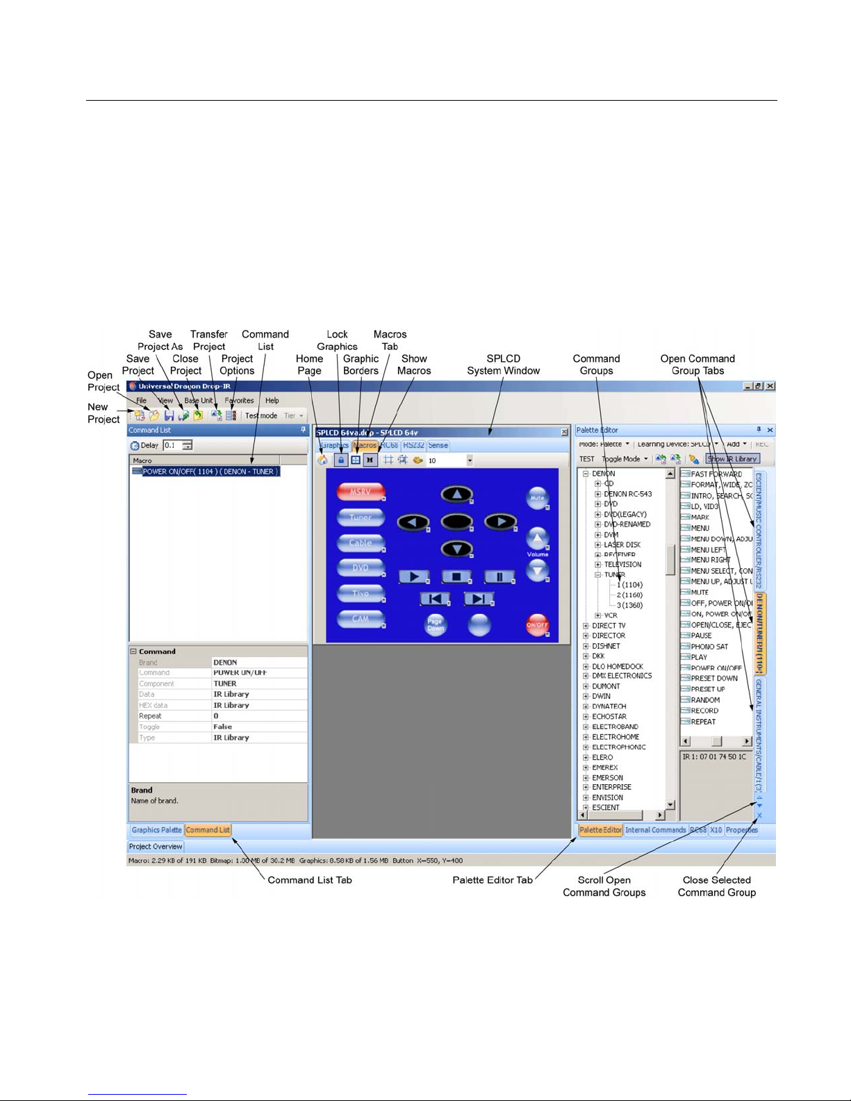
SmartPad LCD™ Page: 53
PLACING COMMANDS ONTO THE GTL’s (Creating Macros)
All Commands – IR, Hex and RS232 should be confirmed and tested before placing any commands on GTL’s.
IR, Hex and RS232 Commands are all placed on GTL’s in the same manner a nd all can be programmed to the
same GTL for use as a Macro Sequence.
NOTE: At this point, the SPLCD Source and Function GTL’s should already be configured on the Virtual
SPLCD in the SPLCD System Window. If this has not been done, return to Section: Creating the Graphical
User Interface (GUI).
With the SPLCD Project open, resize and configure the windows as shown in Figure 40.
NOTE: In the SPLCD System Window, click the Macros Tab. This will open the Command List Window and
lock the GTL’s in place, so they don’t accidentally get moved while placing commands.
© 2008 Xantech Corporation
Figure 40 – Macro Programming Screen
Page 54

Page: 54 SmartPad LCD™
SELECTING IR AND RS232 COMMAND GROUPS FROM THE PALETTE EDITOR
1. Click the Palette Editor Tab to open the Palette Editor. (Click the Auto-Hide Button (thumb tack) to hold
the window open if it has been hidden in the margin.)
2. In the Palette Editor Menu Bar, click Show IR Library so it is highlighted in dark blue.
3. Click on the appropriate Brand (Denon, Escient, etc.). A sub-directory of available components will open.
4. Click on the appropriate Component (CD, DVD, SAT, etc.). A sub-directory of IR and RS232 Command
Groups will open.
5. Click the appropriate Command Group for the components/devices being controlled with the SPLCD
being programmed.
NOTE: As multiple Command Groups are selected, each will appear as a Tab in the margin, so they can
be easily selected while placing commands on the GTL’s without having to scroll through the Brand/
Component List every time a different group is needed. The selected Command Group Tab will highlight
orange and the groups can be scrolled and closed using the buttons at the bottom of the Palette Editor.
ASSOCIATING COMMANDS TO GTL’S (DRAG AND DROP COMMANDS)
Auto-Fill IR Commands
Auto-Fill is the Express Lane to associating IR Commands to GTL’s. Auto-Fill will automatically populate all
buttons with Keywords associated that have been placed on an open Page in the SPLCD System Window with
IR Commands. Keywords are search tools used by Universal Dragon for the Auto-fill process. Associating
‘Keywords’ to a button such as Play, Stop, Volume UP, Volume DOWN, Menu UP, Menu DOWN, etc, allows
Universal Dragon to automatically associate specific commands from the Command Groups to Source and
Function Buttons placed on a Source Page in the System Window. (i.e. If Play and Stop buttons have been
placed on a Page, and a Command Group is dragged onto the screen, Universal Dragon will associate the
commands titled Play and Stop with those buttons.) To Auto-Fill an SPLCD Page:
1. Open a Source Page that has been configured with all required Source and Function GTL’s.
2. In the Palette Editor Window, select the appropriate Brand and Component from the IR Library.
3. Click and Drag the appropriate IR Command Group onto a blank space on the SPLCD Page in the
System Window. A Message Window indicating the number of IR Commands that were associated to
that page will appear.
NOTE: Having the ‘M’ (show macros) Icon selected in the Tool Bar will assist in indicating which buttons
do and do not have commands associated.
4. Click each button and check the associated command in the Macro Command List. Sometimes an
incorrect command will get placed due an ambiguous Keyword.
5. Manually delete and replace commands as needed.
Manually Associating IR Commands to GTL’s
1. Select the Macros Tab in the SPLCD System Window.
2. In the Universal Dragon Tool Bar, click the Show Macros Icon. It will highlight. A small ‘M’ will appear next
to each button that has any commands (single or sequences) associated. This provides a useful reference
to be sure no buttons go un-programmed.
3. Click a Source Button on the virtual SPLCD.
4. Select the appropriate Command Group Tab. Click the appropriate command from the Function List.
The code name (function/brand/component) for that button will appear in the Command List Window.
NOTE: Typically, because this is a Source Select Button an Input Command such as Tuner, CD, DVD,
etc. would be appropriate. If additional commands are required, such as a specific audio mode to
correspond to the selected source, or a play command to automatically play the source when selected,
select Command Groups and click Functions as needed to create Macro Sequences. (See Section:
Programming Sequences below for additional information.)
5. With the Source Button selected in Step 3 above still selected, on the virtual SPLCD, click a Function
Button for that source. Select the appropriate Command Group Tab for that source and click the
appropriate command for the selected Function Button in the Function List.
© 2008 Xantech Corporation
Page 55

SmartPad LCD™ Page: 55
NOTE: To add additional commands to the same button, select Command Groups and click Functions as
needed to create Macro Sequences. Up to 40 Commands can be placed under each programmable
button (See Section: Programming Sequences below for additional information.)
6. Repeat Steps 3-5 for all Source and Function GTL’s.
Programming Sequences (Macros)
All programmable buttons on the SPLCD can be programmed to send Macro Sequences of up to 40
commands. Typically, Volume and Channel, UP/DOWN Buttons would not be programmed for Sequences and
there may be buttons for specific functions, given the component/device, that are also not suited for sequences.
However, on a purely technical level, any button on a SPLCD can be programmed for a Macro Sequence.
1. Click the button to be programmed.
2. Open all Command Groups to be used in the sequence.
3. Select the Command Groups, and click on the commands in the order that the sequence is to be sent.
4. The order of the command s in the se quence can be changed by simply dragging the command towards the
desired position in the list. Press and hold the left mouse button with the cursor over the desired command.
While holding, drag the command to the desired position in the list and release.
NOTE: As you drag a command upward in the list and you want the command between two existing
commands, drop it on the lower command. As you drag downward, drop it on the upper command.
Timed Delays
Timed Delays can be placed between commands in a Macro Sequence. This is sometimes nece ssary in
sequences when a delay is needed between two commands to allow a device to respond completely to the
previous command. (i.e. After a POWER ON command is issued, a delay is usually necessary before the next
command will be recognized and should be added so the source components don’t start playing before the amp
or receiver has had a chance to power up and switch on its output. Another effective use for delay is between
commands when entering multiple digit channel commands to a Cable Box or Satellite Receiver to allow the
box to recognize each command.)
1. In the Command List, click the ▼ and ▲ arrows in the Delay Box for the amount of delay between
commands in .1 second increments up to 30 seconds (i.e. 2 = 2 seconds) or simply highlight the number in
the Delay Box and enter the number using the keyboard.
2. Click Delay, or if entering from the keyboard simply hit Enter on the keyboard. This will place the delay at
the end of the Command List and the delay time appears as a step in the sequence.
3. Left Click and Drag the Delay (5 Seconds) line and drop it between any two commands in the Command
List.
NOTE: As you drag a command upward in the list and you want the command between two existing
commands, drop it on the lower command. As you drag downward, drop it on the upper command.
Repeat Commands
Commands can be repeated to extend the amount of times the command is issued. This is sometimes
necessary for STOP commands or any commands that seem to be intermittent with a short button press. Many
© 2008 Xantech Corporation
Figure 41 – Delay in a Sequence
Page 56

Page: 56 SmartPad LCD™
brands of projectors look for extended OFF commands to avoid accidentally turning projectors off to protect
bulbs from unnecessary power cycles. To repeat an IR Command:
Figure 42 – Repeating an IR Command
1. Right click the command in the Command List, select Repeat from the pop-up and roll the cursor into the
blank pop-up. A text block will appear in the blank pop-up.
2. Enter a numeric value with the keyboard for the number of times the command is to repeat.
3. Click any inactive location on the screen (no GTL) or press Enter.
Delete A Command From the Command List
1. In the Command List right-click the command or delay to be deleted.
2. Select Delete from the pop-up and the command or delay will be removed from the Macro Command
List.
Testing Commands Placed on the Virtual SPLCD
Commands placed under buttons on the Virtual SPLCD can, and should, be tested prior to downloading to the
actual SPLCD. To test placed commands, the PC running Universal Dragon must be connected to the SPLCD
via the RS232 or USB Programming Port. The IR output of the SPLCD should be connected to a
Connecting Block as shown in Figure 8, Page 17. Connect IR Emitters to the appropriate outputs on the
connecting block and attach them over the IR eyes on the components being tested.
NOTE: If RS232 Commands have been placed under any GTL’s, the SPLCD must be connected to the RS232
controlled device with an RS232422 as described in Section: Testing RS232 Commands/Using SPLCD Test.
1. In the Universal Dragon Tool Bar, click Test Mode so it is highlighted in dark blue.
2. Click a GTL Source or Function Button in the SPLCD System Window with placed IR commands to be
tested. (i.e. The MSRV Source Select Button).
3. Each command and delay in the Command List will highlight red as it is being output from Universal
Dragon. The associated command(s) should output from the emitters and control the connecte d devices as
designed.
4. Test all Source and Function GTL’s to confirm programming.
5. Deselect the Test Button when testing is complete.
6. Make necessary changes to button programming as needed following the steps in the previous sections
until all buttons are executing properly.
© 2008 Xantech Corporation
Page 57

SmartPad LCD™ Page: 57
TRANSFERRING THE PROJECT
With all commands tested, the project can now be transferred to the SPLCD.
NOTE: Before continuing, make sure the PC is properly connected to the SPLCD by running a Base Unit/ Who
Am I. A proper connection will return a window with product information on the connected Panel. See Section:
Verifying Com Port Communication/Who Am I for additional information. If programming for the current
project will include advanced configuration you may also transfer the project at this time for a System Test
before getting into more complex system features. To transfer the project to the SPLCD:
1. In the Menu Bar, click Base Unit and select Who Am I from the pop-up. Verify a valid response is
received.
2. In the File Menu select Transfer Project or click the Transfer Project Icon (
3. A File Transfer Dialog Window should appear on the PC and start showing progress of the transfer
process. During this time, the SPLCD Display will turn white with an activity wheel in the middle of the
display to show activity.
4. When the transfer is complete the message: Transfer Succeeded will appear in the File Transfer Dialog
Window. Click OK.
5. Test all Buttons on the SPLCD to confirm the Project Transfer.
6. In some cases, recalibration may be necessary after a Project Transfer or Firmware Update. See
Section: Calibration for additional information.
) in the Tool Bar.
SAVING THE PROJECT
Once the Project has been transferred and all functions tested and confirmed the project sho uld be saved for
future reference or upgrades.
Save Project
1. In the File Menu, select Save Project or in the Tool Bar, click the Save Project Icon.
2. The Save As Window will appear for a new, unsaved project. (No window will appear when saving new
work on a previously saved project.)
3. The default Folder for Universal Dragon™ Projects is:
C:\Program Files\Xantech\Universal Dragon vX.X\Projects. Navigate to this location if the Projects
Folder does not appear in the Save In Box.
4. Enter a name for the project in the File Name Box. (The client’s name, ie: ‘Jones Home’ is a good way to
keep track of individual projects.)
5. Click Save.
6. To close a project without saving changes, In the File Menu, select Close Project. In the Save Window,
click NO. The project will close without saving changes. The project will still be available for future use, in its
last saved form.
Save Project As
When programming a project for a new client that is similar or identical to an existing project, Open the existing
project. In the File Menu select Save As, then enter the new file name as described in Step 4 above. The
project will be saved with the new file name. At this point, the project can be transferred to the Controller if no
additional changes are required, or after making the necessary changes for the new client.
File Size
The Maximum file size for a SPLCD Project is 3MB for SPLCD39G. SPLCD64G/V prior to Serial Number
071118 max file size is 32MB. SPLCD64G/V Serial Number 071119 and higher max file size is 1GB.
Project Transfer Interruption
Once a Project Transfer starts downloading, if it is interrupted at any point during the download, the SPLCD
may lock up and you may lose communication with the SPLCD. This can occur when the PC goes into screen
saver or standby power mode, the SPLCD loses power or the programming cable becomes disconnected.
1. Press and release the Reset Button on the SPLCD.
© 2008 Xantech Corporation
Page 58

Page: 58 SmartPad LCD™
2. After approximately five seconds, the SPLCD will ask you if you wish to abort loading the Project. Touch
the display within 10 seconds of this message being displayed to force the system to abort loading the
project.
3. At this point you should be able to do a Project Transfer from Universal Dragon to load your project into
the SPLCD.
4. If the download does not start, check the PC’s Port Settings to make sure the appropriate Port is selected.
5. Please also note in an installed environment, power fluctuations may also cause the Abort Project Load
message to appear. In this scenario, don’t abort project load just yet. Try letting project load first.
© 2008 Xantech Corporation
Page 59

SmartPad LCD™ Page: 59
Section 5: Advanced Programming
RC68 IR CODE TRIGGERED SEQUENCER
The SmartPad LCD™ Touch Screen Controller can generate IR and/or RS232 command sequences that are
triggered by single RC68 commands received at the SPLCD’s IR Receiver (Figures 2a, 2b – Item 2). This
feature can be useful in eliminating long sequence execution from hand-held controllers and also allow a wider
range of programmable remotes that can be used with the SPLCD (i.e. Remotes that do not allow sequence
programming).
When the SPLCD receives a specific RC68 command (Default Code Group C9), via the built-in IR Receiver or
an external IR Receiver, the system will output a sequence of commands. The sequence can be any
combination of IR Commands, Internal SPLCD Controller Commands, and RS232 commands. This means a
basic programmable remote can trigger any command (IR, RS232 or Xantech ‘Internal Commands’) to
communicate with all devices connected to the SPLCD. A total of 55 Macro’s can be triggered in this fashion.
Figure 42 – RC68 IR Code Triggered Sequencer
PROGRAMMING RC68 TRIGGERED SEQUENCES
Programming the RC68 Triggered Sequencers is similar to programming macros under GTL buttons.
1. Click on the RC68 Tab in the SPLCD System Window.
2. Open all the IR and RS232 Command Groups for the devices to be controlled in the RC68 Triggered
sequence.
3. Select the RC68 Sequence Trigger Command to be programmed. (i.e. click on the 80 Button or any of
the other 54 buttons shown under the RC68 Tab so it is highlighted in yellow.)
4. Click the appropriate Command Group Tab for the first IR or RS232 Command to be associated with the
selected RC68 Trigger Command. The command name (function/brand/component) will appear in the
Macro Command List Window.
5. Repeat Steps 2-4 for all IR/RS232 Commands to be associated to this RC68 Trigger Command. A
maximum of 40 commands may be placed under each RC68 Trigger, including Delay Commands).
6. Repeat Steps 2-5 for any other RC68 Triggers. (55 Triggers total.)
NOTE: Creating a written record of each RC68 Trigger command button and a brief description of its macro
function is recommended for reference. (i.e. Button 80 = Turn on HK Receiver and Escient Server, Select
© 2008 Xantech Corporation
Page 60

Page: 60 SmartPad LCD™
CD Input and Play Server.) Use the blank pages at the end of this manual and keep it in the Customer File
for future use.
TEACHING RC68 TRIGGER COMMANDS TO A UNIVERSAL REMOTE
The Macro Sequences created in the previous section must be triggered by RC68 Comman ds when issued
from a Universal Remote, another keypad or an IR Receiver connected to the SPLCD’s IR IN Bus (Figure 3 –
Item 19). This requires the use of a RC68X Handheld Programmer (sold separately) or Universal Dragon
Software (Xantech programmable devices only).
NOTE: The programming in the following sections requires use of Xantech RC6 8 Commands to trigger Macro
Sequences from the SPLCD. Non-Xantech branded remotes, keypads and other controllers will need to be
programmed with RC68 Commands that are generated by either a RC68+ or RC68X. The older RC68 will work,
but it does not provide the complete code set available for creating triggered macros. For simplicity, these
codes will be generically referred to as RC68 commands in the following sections.
1. On the rear of the RC68 Hand-Held Programmer, set the Code Group Dials to C9. (No Overlay needed)
2. Set the Universal Learning Remote to be used to learn mode per the manufacturer’s instructions.
3. Select the button on the Universal Remote that is to issue the RC68 Trigger Command and locate the
properly numbered RC68 Button on the RC68 Hand Held Programmer (i.e. Button 80).
4. Teach the RC68 Command to the Universal Remote per the remote’s instructions.
5. Repeat Steps 2-4 for all RC68 Trigger Commands to be used.
PROGRAMMING THE URC-2B/P FOR USE WITH SPLCD RC68 TRIGGERED SEQUENCES
Programming a Xantech Model URC-2B/P (Black or Platinum) Universal Remote to trigger the programmed
RC68 sequences can be done in two different ways: either identically to the procedure above (teachi ng directly
with the RC68 Hand Held Programmer) or by using Universal Dragon Software. To program the URC-2 for
operation with the SPLCD using Universal Dragon, please do the following:
1. Either open an existing or create a new URC-2B/P Project.
2. With the URC-2 Base Unit open, click the RC68 Tab in the Palette
Editor.
3. Click the
Options Tab on the RC68 Command Palette.
4. Under Xantech Model select SPLCD from the pull-down. If SPLCD is
not found in the pull-down, select MAC1 as shown in Figure 43.
5. Change the Code Group to C9.
6. Click the RC68 Remote Tab.
7. Click the button on the virtual URC-2 to be used to trigger the Macro
Sequence created on the SPLCD. (i.e. CD Button as shown in Figure
44.)
8. Click the RC68 Trigger Command Button in the RC68 Command
Palette that corresponds to the Macro Sequence programmed on the
SPLCD. (i.e. button 80)
9. Confirm the proper RC68 Command is shown in the Macro Command
List.
10. Repeat Steps 7-9 for all RC68 Triggered Sequences
RC68 Palette Settings in Drag450
Figure 27a:
programmed on the SPLCD that are to be triggered from the
URC2.
Figure 43 – RC68 Options
© 2008 Xantech Corporation
Page 61

SmartPad LCD™ Page: 61
Figure 44 – URC-2 RC68 Macro Trigger Programming
RS232 INPUT TRANSLATOR
The SPLCD Touch Screen Controller has the ability to receive specific Xantech RS232 ASCII strings and
associate them to individual IR Commands or IR Macro Sequences to control any number of IR controlled
devices. This allows a central PC (or other RS232 unit) to control any IR device connected to the SPLCD IR
Bus Output.
NOTE: For RS232 Communication, a RS422232 Converter and 12V DC Power Supply (Xantech Part #
781ERGPS) (both sold separately) are required. For RS232 Connections, see Figure 11 in Section 2 of this
manual. A Null Modem cable may be necessary for communicating with the Component or Device. Check the
manufacturer’s specification to see if this is required.
© 2008 Xantech Corporation
Page 62

Page: 62 SmartPad LCD™
Figure 45 – RS232 Input Translator
PROGRAMMING IR COMMANDS AND SEQUENCES
The RS232 Input Translator gets programmed in the same manner as programming macros under GTL Buttons
and RC68 Sequence Triggers. Commands from the IR Command Groups can be associated with any of the
128 available ASCII strings. This allows programming up to 128 different ASCII command strings to control
external IR devices.
Selecting IR Command Groups from the IR Code Library
1. If not already open, in the View Menu, select Palette Editor or click the Palette Editor Tab.
2. In the Palette Editor Menu Bar, select Show IR Library so it is highlighted dark blue.
3. In the Brand/Component List, click the appropriate Brand. (Harmon Kardon, Sony, etc.) A sub-directory
of component types will open.
4. In the Component sub-directory click the appropriate Component Type (i.e. VCR, TV etc.). A subdirectory of Command Groups will open.
5. Select the proper Command Group. (Be sure to select an IR Command Group. The RS232 Input
Translator only outputs IR commands.)
6. Repeat Steps 3-5 for all components/commands being used in the macro. As multiple Command
Groups are selected, they will stack in the margin as Tabs. Click a Tab to show the commands for that
Command Group in the Function List.
Associating RS232 Commands with IR Commands
1. In the System Window, select the RS232 Tab. (Figure 45)
2. In the RS232 Window, select an ASCII Command String. The selected string will be highlighted in a blue
background.
3. Click the Tab for the Command Group with the first IR command to be associated to the selected ASCII
Command string.
4. The code name (function/brand/component) for the selected IR Command will appear in the Macro
Command List.
© 2008 Xantech Corporation
Page 63

SmartPad LCD™ Page: 63
5. Repeat Steps 3-4 for all IR commands to be associated to this Command String. A maximum of 40 IR
Commands may be associated with each string.
6. Repeat Steps 2-5 for all required ASCII Strings, up to 128 total.
NOTE: It is recommended to write down the ASCII command string and a brief description of its corresponding
MACRO function. Each ASCII String will need to be entered into the controlling PC/device as it appears
opposite the COMMAND Number. (i.e. to trigger ‘Command 000’ you will need to issue !000MC+ as the ASCII
command string from the controlling PC/device.)
Testing Commands in the RS2322 Input Translator
Commands associated with the ASCII Command strings in the RS232 Input Translator should be tested prior to
downloading to the SPLCD. To test commands, the PC running Universal Dragon must be conne cted to the
SPLCD front panel Com Port or USB Port and emitters must be connected to the SPLCD IR Bus (Figure 8,
Page 17).
1. In the Universal Dragon Menu Bar, click Test Mode so it is highlighted dark blue.
2. In the System Window, select an ASCII Command String with associated IR codes to be tested. (i.e.
Command MC000+). The command string should now be highlighted dark blue.
3. The IR Commands listed under the Macro Command List for that selected ASCII Command should now
be executed in order of appearance out of the IR Bus on the SPLCD Rear Panel.
4. Verify that all components/devices have responded to the Macro Sequence as designed.
NOTE: RS232 commands may also be placed under the RS232 trigger macro to go ba ck to the issuing RS232
device. For testing RS232 commands placed under this macro, the device needs to be connected to the DB9
RS232 Port of the RS422232 Converter as shown in Figure 11.
SENSE TRIGGER MACROS
The Status Terminal located on the rear of the SPLCD (Figure 3 - Item 19c) may also be utilized to trigger a
Macro Sequence (IR and/or RS232). Two macros can be triggered when the incoming Status Voltage is either
High (5-30V DC) or Low (0V DC). This is very useful for numerous applications such as a doorbell trigger circuit
to mute a particular zone, set a preferred lighting scene when a component is turned on or turn off all lights and
A/V equipment when an alarm system is activated.
© 2008 Xantech Corporation
Page 64

Page: 64 SmartPad LCD™
Figure 46 – Sense Trigger Setup
Programming The Sense Input
1. In the SPLCD System Window, select the Sense Tab.
2. In the Sense Setup Block, under Trigger Macros, click Trigger On. The button will appear unshaded.
3. In the Palette Editor, from the Command Groups, select the appropriate IR and/or RS232 Command(s)
to be output with a positive sense input (applied voltage = + 5 to 30V DC).
4. In the Sense Setup Block, under Trigger Macros, click Trigger Off. The button will appear unshaded.
5. In the Palette Editor from the Command Groups, select the appropriate IR and/or RS232 command(s) to
be output with the absence of a sense input (applied voltage = 0V DC).
6. Selected Commands will appear in the Macro Command List.
7. In the Universal Dragon Tool Bar, click the Project Options Icon (
). Under the Settings Tab, be
sure Line Input Role is set to Input. See Section: Options Settings/Track LED Settings and Line Input
Role Settings for additional information.
INTELLIGENT POWER MANAGEMENT
The Status Input can also be used for sensing the power state of an external device to prevent unwanted
power commands from being issued when not desired. If the sensed device has a Status Output (or a
switched or sensed AC outlet with a DC Power Supply or 12V output), when a Source GTL is pressed, if the
Status Line is Low (Status = 0V) the Power ON Command will be initiated. If the Status Line is High
(STATUS = 5 to 30V DC), the Power ON Command will not be output.
This feature will also allow for a System Power Macro to be initiated whenever a Source GTL is pressed. In
this application, the main system component, A/V Receiver, Multi-room Controller, etc. must have a common
12V DC Control output that indicates System State (ON/OFF). In this case, when a Source GTL is pressed, if
the System Status Line is Low (Status = 0V) the Power ON Macro will be initiated. If the System Status Line
is High (STATUS = 5 to 30V DC), the macro will not be output.
Programming Intelligent Power Management
1. In the SPLCD System Window, select the Sense Tab.
2. In the Sense Setup Block, Select Intelligent Power Management.
3. In the Palette Editor from the Command Groups, select the appropriate IR and/or RS232 command(s) to
be output when the Status Line is Low (Status = 0V).
4. Selected Commands will appear in the Macro Command List.
© 2008 Xantech Corporation
Page 65
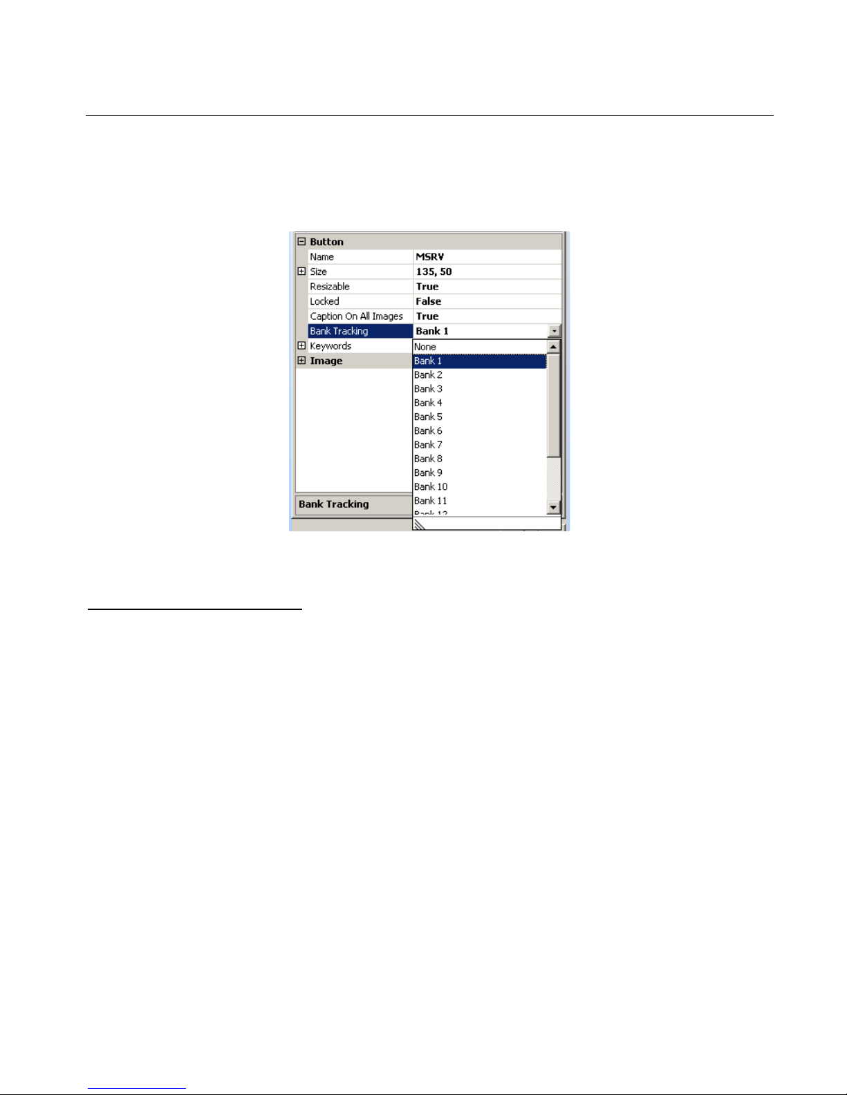
SmartPad LCD™ Page: 65
ASSIGNING BANK TRACK CODES TO SOURCE GTL’S
By assigning discrete Bank Track Codes to each Source Button, the SPLCD can work in conjunction with
accompanying learning hand held remotes (similar to Xantech Model URC-2P/B) or other Xantech Keypads or
SPLCD panels in the same zone. When a source is changed on the accompanying hand held remote (or
another SPLCD panel), the Source Pages on all keypads will change to remain in sync with the current Source
selection.
Figure 47 – Assigning Bank Track Codes to Source GTL’s
Programming Bank Track Codes
1. In the SPLCD System Window, select the Macros Tab.
2. Right-click on a Source Button and select Properties or in the Palette Editor, select the Properties Tab.
3. In the Properties Window, at the bottom of the window, in the Button Attributes, click Bank Track and
select the appropriate Bank Track Code, for the selected source, from the pull-down.
NOTE 1: Default Code Group for Bank Track codes is D8 and can be found under the Project Options
Icon in the Tool Bar.
NOTE 2: The URC-2P/B is pre-programmed with Bank Track Codes 1-8 and is directly compatible with
the SPLCD Bank Track Code system.
© 2008 Xantech Corporation
Page 66

Page: 66 SmartPad LCD™
Section 6: Options Settings
In the Project Options Window in Universal Dragon, the user can change the settings for RC68 Code Group,
Bank Track Code Group, Status Line and LED Operation, Backlight Control, Display Orientation, RS232 Port
Settings, MRC88 Emulation and Password.
Figure 48 – SPLCD Options Settings
RC68 CODE GROUP
The RC68 Code Group setting refers to the group of IR codes that will be used to trigger RC68 Sequences as
discussed in Section 5. The number associated with this Code Group refers to the dial setting on the rear of a
RC68+/X Handheld Programmer (Figure 49). The SPLCD Default Code Group is C9. This setting only
needs to be changed if multiple SPLCD’s are connected in parallel and have different control functions, if they
are all within line of sight of a remote programmed with Bank Track Codes, or if there is an IR code group
conflict with some other device used in the same system.
© 2008 Xantech Corporation
Page 67

SmartPad LCD™ Page: 67
Figure 49 – RC68+/X Handheld Programmer Code Group
BANK TRACK CODE GROUP
When an SPLCD is used in a system in conjunction with other controllers (i.e. handheld remotes or other
SPLCD panels) in which the equipment can be controlled from multiple locations, the SPLCD panels have th e
ability to track source selections simultaneously for in-sync operation for the current source selection if the
remotes and SPLCD’s are all configured with the same Bank Track Codes and the SPLCD’s are connected in
Parallel.
Example: If a user walks into a room and selects DVD on the SPLCD and then decides to select CD using a
handheld remote, the SPLCD will automatically switch to the CD source page. The same thing will happen
when multiple SPLCD’s are connected in parallel and a selection is made on o ne panel, the other panels will
automatically switch to the source page selected.
The default Bank Track Code Group is D8.
TRACK LED SETTING
The Status LED (Figure 2 - Item 3) can be configured to track the Status Terminal on the rear of the SPLCD
(Figure 3 – Item 19c). If this is desired LED Track should be selected (check mark). The default setting is
de-selected (no check mark).
When the LED Track is selected (check mark), the Status LED will turn ON whenever a positive voltage (530VDC) is present on the Status Terminal on the rear of the SPLCD. Whenever this voltage is LOW (0V DC)
the Status LED will turn OFF.
This works in conjunction with the Line Input Role setting.
LINE INPUT ROLE SETTING
The Status Terminal on the rear of the SPLCD (Figure 3 – Item 19c) can be configured as either an Input to
sense the state of an external device or as an Output to control an external device.
© 2008 Xantech Corporation
Page 68

Page: 68 SmartPad LCD™
Input
When Input is selected in the Line Input Role Block and a 5 to 30V DC signal is present on the Status
Terminal on the rear of the SPLCD, the following event/actions can be triggered:
1. The Status LED on the SPLCD Front Panel will turn ON [Requires LED Track to be selected, (check
mark)].
2. Initiate a Sense Trigger Macro (if one is associated to the System Window/Sense Tab/ON Button).
3. Utilize Intelligent Power Management (if selected at: System Window/Sense Tab/Intelligent Power
Management).
NOTE: Items 1&2 or 1&3 may be programmed to occur simultaneously.
Output
When Output is selected in the Line Input Role Block, the Status Terminal becomes a switchable12V DC
Output. When the Internal Command: Set Line Status/ON is placed under a GTL and that button is pressed,
the Status Terminal outputs 12V DC. When the Internal Command: Set Line Status/OFF is placed under a
GTL and that button is pressed, the Status Terminal outputs 0V DC. This can be utilized to control an external
device via a 12V trigger when an appropriately configured GTL is pressed (i.e. Control a Projection Screen, a
Lift, Drapes or an amplifier with a 12V DC Control Input).
Note: The Status Output is rated at 15mA maximum.
BACKLIGHT SETTINGS
This sets the LCD Backlight to stay ON for a specified amount of time after the display is last touched. The
Backlight can be set to stay ON from 1-30 seconds in 1 second increments, 1-30 minutes in 1 minute
increments or Always ON.
NOTE: The internal IR receiver is disabled whenever the Backlight is ON to avoid interference. Therefore if
Always ON is selected, the IR Receiver will not be active.
DISPLAY ORIENTATION
The LCD Display needs to be configured for the proper viewing angle according to the positio n it will be
installed with regard to the user. (Figure 50)
Up
Select this setting if the SPLCD will be installed at a height equal to or above the user’s eye level. (IR Sensor
on the right side, Rear Panel in normal orientation.)
Down
Select this setting if the SPLCD will be installed at a height equal to or below the user’s eye level. (IR Sensor
on the left side, Rear Panel upside down. If the SPLCD is not oriented as described, the graphics will appear
upside down.)
© 2008 Xantech Corporation
Page 69

SmartPad LCD™ Page: 69
UP VIEW
DOWN VIEW
Figure 50 – Display Orientation
RS232 SETTINGS
To configure the settings of the Serial Port located on the SPLCD Rear Panel (Figure 3 – Item 21), if not
already open, in the Menu Bar, click on the Project Options Icon and in the Options Window select the
RS232 Tab. This will display all of the configurable RS232 settings for the Serial Port. (Figure 51)
NOTE: The Serial Port on the SPLCD Rear Panel is a RS422 Port. Use of this Port requires a Xantech
RS422232 Converter or a RS2321X8 Router and a 781ERGPS Power Supply to communicate with RS232
controlled devices.
Figure 51 - RS232 Port Default Settings Figure 52 – RS232 Port Router Settings
© 2008 Xantech Corporation
Page 70

Page: 70 SmartPad LCD™
RS232 Port Default Settings
Use this configuration when controlling a single RS232 device from the SPLCD.
To change Baud Rate, Data Bits, Stop Bits or Parity settings, click on the corresponding pull-down and select
the desired setting per manufacturer’s specification for the device to be controlled via RS232. Default settings
for all are shown above in Figure 51. If controlling a Xantech XDT Tuner or XMUSIC Server, select the
appropriate Driver from the pull-down, when configuring the associated Port.
NOTE: If controlling a Xantech XDT Tuner or XMUSIC Server, use a Null Modem Cable (Part No. 05913560).
RS232 Port Router Settings
Use this configuration when controlling multiple RS232 (or RS422) devices (up to eight) from the SPLCD using
the RS2321X8 Router. See: RS2321X8 Router Installation Instructions for complete instructions.
1. In the Router Block, select (check mark) Xantech RS232 Router Enable.
2. To have the RS2321X8 always return to a specific port (default) select (check mark) Router’s Default
Port Enabled and select the appropriate Port from the Default Router Port pull-down.
3. To set the individual Router Ports to the appropriate Protocol, using the Router Port pull-down, select
each Port individually, (Port1, Port 2, Port 3, etc.) and set the Baud Rate, Data Bits, Stop Bits and Parity
settings for each device by Port, per the manufacturer’s specification for the device connected to the
selected RS2321X8 Port.
4. If controlling a Xantech XDT Tuner or XMUSIC Server, select the appropriate Driver from the pull-down,
when configuring the associated Port. (i.e. Port 1 = XDT, Port 2 = Xantech Music Server.)
© 2008 Xantech Corporation
Page 71

SmartPad LCD™ Page: 71
Section 7: Appendix
INTERFACING SPLCD with MRC44 (IR Control) & MRC88 (MRC88 Emulation)
The SmartPad LCD™ allows direct integration with Xantech MRC Products via the CONTROL and
EXPANSION RJ45 Terminals on the SPLCD Rear Panel (Figure 3 – Items 13 & 14). Connecting either of
these terminals to a Zone Keypad Connection on the rear of a MRC44 or MRC88 allows IR control of the MRC
and any components connected to the MRC Controller.
NOTE: An external 16VDC Power Supply must be connected to the +16V In Only and GND Terminals on the
IR Bus Connections on the SPLCD Rear Panel. (Figure 3- Items 19a & 19b) A MRC cannot power a
SPLCD.
MRC88 EMULATION MODE: FEATURE DESCRIPTION & PROGRAMMING
SPLCD/MRC88 EMULATION MODE
The full line of SmartPad™ LCD Controllers can be seamlessly integrated into a new or existing MRC88 o r
MRAUDIO8X8 System over the existing CAT5 cable. This allows the SPLCD to initiate any macro programmed
in the MRC88 Controller without the use of IR commands. All Macro Programming resides in the MRC88
allowing for ease of initial programming and any upgrades that should be required. For simplicity, MRC88 and
MRAUDIO8X8 will be referred to as MRC88.
Connecting the SPLCD to the MRC88 Controller
1. Connect one end of the CAT5 to the appropriate Zone Keypad Terminal on the MRC88 Rear Panel and
the other end to the Controller Terminal on the SPLCD Rear Panel.
2. Connect a 16V DC Power (Xantech Part # SPLCDPS1) directly to the IR Bus +16V DC and GND
Terminals on the SPLCD Rear Panel.
NOTE: The SPLCD cannot be powered directly from the MRC88 Controller.
3. If using multiple keypads in a single zone, the last keypad in line must have the Zone Termination Jumper
installed.
NOTE: SPLCD comes with the Zone Termination Jumper installed by default.
Configuring Dragon Drop SPLCD for MRC88 Emulation Mode
1. Program the MRC88 as you would for a standard MRC88 Keypad using both Tier 1 and Tier 2 on the
buttons for added functionality if desired.
2. Create the graphic layout for an SPLCD Project in Universal Dragon as appropriate for the system being
controlled. Place Source and Function GTL’s as required.
3. After all of the GTL’s are laid out, as is done in a standard SPLCD project, click the Project Options Icon
in the Tool Bar. The Options Window will appear. (Figure 53)
4. Click the MRC88 Emulation Tab. Select (check mark) the box: Emulate MRC88 Keypad.
5. If you are using multiple keypads in a single zone, set each keypad to a unique Keypad Address. Up to
four keypads can be used in a single zone.
NOTE: If using standard MRC88 Keypads in conjunction with the SPLCD in a zone, you must also set the
MRC88KP Address Jumper to a unique address.
6. Under MRC88 Source Names enter the names as they appear in the Universal Dragon MRC88 Project.
NOTE: This is necessary for proper Source Name display when using the MRC8 8 Status function.
© 2008 Xantech Corporation
Page 72

Page: 72 SmartPad LCD™
Figure 53 – Options Window/MRC88 Emulation
Programming SPLCD for MRC88 Functionality
Once the SPLCD has been configured for MRC88 Keypad Emulation, you can point any GTL on the SPLCD to
a specific macro within the MRC88 Controller.
1. In the SPLCD System Window, click the Macros Tab to lock in the current GTL Button layout.
2. In the SPLCD System Window, select a Source Button.
3. In the Palette Editor Window, click the Internal Commands Tab.
4. In the Internal Command Window, select MRC88 Button Emulation from the pull-down.
NOTE: The MRC88 Internal Commands are pointers to button locations within the MRC88 Controller.
The SPLCD can now initiate whatever Macros are programmed within the MRC88 under these buttons.
5. Scroll through the list and associate the SPLCD Button to the appropriate MRC88 Internal Command to
initiate the Macro programmed under that specific button within the MRC88 Controller. (i.e. In the SPLCD
System Window, click the Source 1 Button (DVD) and then select Src 1 from the MRC88 Button
Emulation List as shown in the example below.
© 2008 Xantech Corporation
Page 73
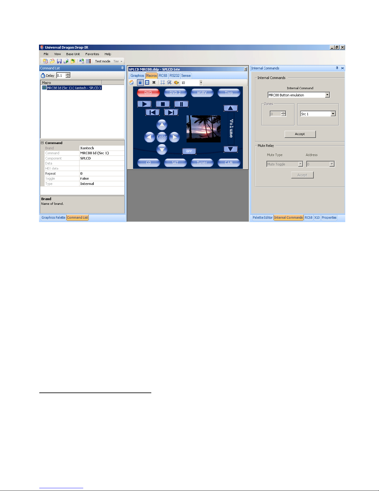
SmartPad LCD™ Page: 73
Figure 54 – Assigning MRC88 Internal Commands to GTL’s
6. Repeat Step 5 for all Source Button GTL’s.
7. Repeat the same procedure for all Function Button GTL’s that will emulate the Function Buttons on a
MRC88 Keypad (i.e. Play, Stop, Pause, etc).
8. You can also associate a SPLCD Button GTL to a MRC88 Tier 2 Macro.
a) In your MRC88 Project, assign the 5 MRC88KP Motion Control Buttons (Play, Stop, Pause, Rew,
FF) as Tier 1.
b) Program Tier 2 as the Menu Navigation Buttons (Up, Down, Left, Right, Select).
c) In the SPLCD Project, select the Button GTL for Play and associate it with the MRC88 Internal
Command: Play.
d) Click the Button GTL for Select and assign it the MRC88 Internal Command: Play Tier 2.
9. Repeat Step 8 for all Button GTL’s on the SPLCD (i.e. MRC88 Volume UP/DOWN, OFF, Mute, etc.) to
emulate all of the Buttons on a MRC88KP.
10. If more button control is needed from the SPLCD additional Function Button GTL’s can be placed and
programmed with IR Commands to pass IR through the CAT5 to the MRC88 Controller as you would in a
standard project for additional control functionality of external devices.
NOTE: To trigger Macro Sequences, setup RC68 IR Triggered Macros in the MRC88 Project. By doing
so, the
SPLCD only needs to send a single IR Command to trigger the Macro Sequence within the
MRC88. This keeps all of the Macro Programming within the MRC88.
Placing MRC88 Objects on the SPLCD
MRC88 Graphic Objects can also be placed on a SPLCD Page to provide the same MRC88 System
Information displayed on a MRC88KP. Objects that can be placed are:
• STATUS DISPLAY: Displays Zone Status, Source Icons, and Zone Linking Information.
• INFORMATION DISPLAY: Displays Xantech XDT Tuner Metadata, Mute, Zone OFF, Priority Lockout
Status, etc.
• HORIZONTAL BARS: Horizontal Bars display Zone Volume, EQ or Balance Level.
• VERTICAL BARS: Vertical Bars display Zone Volume, EQ or Balance Level.
© 2008 Xantech Corporation
Page 74

Page: 74 SmartPad LCD™
To place one or more of these objects on a SPLCD Page:
1. Right click on a blank area of the background (no GTL or PiP).
2. Select Insert MRC88 Object from the pop-up.
3. Select the MRC88 Object: Horizontal or Vertical Volume, EQ or Balance Bar, Informational or Status
Display.
NOTE 1: Once placed on a SPLCD Page, these objects can be moved to any desired location by clicking
and dragging the object. The object colors can be modified to match the Style of the Background and
Buttons by clicking the Properties Tab, clicking Border Color or Color and changing the color selection
in the pull-down.
NOTE 2: The Horizontal and Vertical Bars can be resized for length and width by clicking the Properties
Tab and changing the values under Size. The Status and Informational Displays cannot be resized.
MRC88 OBJECT PROGRAMMING: ADDING VOLUME BAR, STATUS BAR ETC…
TRANSPARENT GTL’S AND MRC88 EMULATION
Combining these two features allows for unique programming possibilities.
Below is an example for creating Interactive Volume Bars so the user can press different areas of the Volume
Bar and have the Zone Volume Level jump immediately to that level. In this particular example we will separate
the Volume Bar into three sections, Low Level, Mid Level and High Volume Level.
This will require programming to both the MRC and SPLCD Projects in Universal Dragon.
MRC88 PRESET VOLUME LEVEL PROGRAMMING
The following Steps will be performed in the MRC88 Project for the system being configured. (Refer to the
MRC88/MRAUDIO8X8 Installation Instructions; Section 5: RC68+ IR Code Triggered Sequencer for
further explanation of the following):
Figure 55 – MRC88 RC68 Volume Preset Macro Trigger Programming
© 2008 Xantech Corporation
Page 75

SmartPad LCD™ Page: 75
1. Within the appropriate MRC88 Project, in the System Window, select the Zone the SPLCD will be
connected to from the pull-down. (Zone 1)
2. In the System Window click the RC68 Tab.
3. In the Palette Editor Window, click the Internal Commands Tab.
4. In the Internal Commands Block, select Set Volume from the pull-down.
5. Select the Zone Number. ( Zone 1)
6. Select the [80] Button on the Virtual RC68 (or any other free RC68 Trigger Button).
7. Select a discrete Volume Level for the Low setting (i.e. 20) and click Accept.
8. Repeat for two other RC68 Trigger Buttons for a Mid Volume level and a Hi Volume Level (i.e. place the
discrete Set Volume Level 40 Command under the [48] Button and the discrete Set Volume Level 50
Command under the [10] Button on the Virtual RC68.
SPLCD / MRC88 PRESET VOLUME LEVEL PROGRAMMING
The following Steps will be performed in the SPLCD Project for the system being configured.
Figure 56 – Configuring MRC88 Volume Preset Triggers
Placing the Volume Bar
1. Right click on a blank area of the Background (no GTL or PiP) and select Insert MRC88 Object, then
select a Horizontal or Vertical Volume Bar from the pop-up options.
2. Place and resize to the desired position.
Creating Transparent GTL’s over a Volume Bar
1. Right click on a blank area of the background (no GTL or PiP) and select Insert Objects then Transparent
Button from the pop-up.
2. Resize the Transparent GTL to cover 1/3 of the Volume Bar and place over the lower 1/3 of the Volume
Bar.
NOTE: Use the Size values in the Properties/Button Attributes for reference and quick adjustments.
© 2008 Xantech Corporation
Page 76

Page: 76 SmartPad LCD™
3. Place two more Transparent GTL’s over the middle and upper 1/3 sections of the Volume Bar.
Assigning the Proper RC68 IR Codes to the Transparent GTL’s
1. In the Palette Editor Window click the RC68 Tab.
2. Click the Options Tab on the Virtual RC68 Palette and choose MRC88 from the Xantech Model drop-
down.
3. Click the RC68 Remote Tab on the Virtual RC68.
4. In the SPLCD System Window, select the Transparent GTL placed on the lower 1/3 of the Volume Bar.
5. Click the [80] Button on the Virtual RC68. In the Macro Command List Window you should see the
command: ‘C (A8,10) (Xantech – MRC88)’.
6. Repeat Steps 4-5 with the RC68 [48] Command associated with the middle Transparent GTL and the
[10] Command associated with the upper Transparent GTL as shown above.
© 2008 Xantech Corporation
Page 77

SmartPad LCD™ Page: 77
PROGRAMMING SPLCD FOR USE WITH MRC44 (ZONE CONTROL)
1. Open a new SPLCD Project.
2. Choose the Base Unit (3.9G, 6.4G/V).
3. Select the Style.
4. In the System Window place 4 Source GTL’s onto the virtual SPLCD.
5. In the Palette Editor, click the RC68 Tab to open the RC68 Palette.
6. In the RC68 Command Window click the Options Tab.
7. In the Xantech Model block, select MRC44 and verify the Code Group setting is the same as that of the
MRC44 (Default Code Group = 48). Click the Palette TAB to return to the RC68 Palette.
8. In the SPLCD System Window, click the Source Button GTL that will select the component connected to
Input 1 on the MRC44 (i.e. Cable as shown in Figure 57).
9. On the RC68 Palette, select Input 1 on the RC68 (Button 00) and verify the proper command description is
shown in the Macro Command List: [(Input 1 (48, 00) (Xantech MRC44)]
10. Repeat Steps 8-9 for all Source Input GTL’s.
11. Place a Source GTL for OFF (if desired). Some Source GTL Style Groups have OFF Buttons already
made. Some will require adding a Caption in the Button Properties Attributes Window after the Blank
Source GTL has been placed.
a.
With the OFF GTL selected, on the RC68 Palette select OFF (button 68) and verify the proper
command is shown in the Macro Command List Window.
12. On the Home Page place Function GTL’s for Volume and Mute Buttons, and associate the appropriate
RC68 commands for each GTL on each Source Page.
13. On each Source Page place Function GTL’s for all desired functions for the device connected to the
associated Input (i.e. Input 1 = Cable, Input 2 = CD, etc.). Using the Palette Editor Command Groups,
associate the appropriate IR Commands with the Source Function GTL’s on each Source Page.
Figure 57 – SPLCD MRC44 IR Control Programming
NOTE: To create Toggle Power or Mute Commands, program the MRC44 using the Toggle Power or Mute
Internal Amplifier Commands as RC68 Triggered Sequences. (See: MRC44 Installation Instructions;
RC68+ IR Code Triggered Sequencer) See Figure 58 below. Place the RC68 IR Trigger Commands that are
© 2008 Xantech Corporation
Page 78

Page: 78 SmartPad LCD™
associated with the Internal Amplifier Commands in the MRC, under the appropriate GTL Buttons when
programming the SPLCD. (Figure 58) (i.e. In the SPLCD programming, the ON/OFF Source GTL will have the
RC68 80 Command in the 48 Code Group placed under it as an IR Command that will be output to the MRC.
The RC68 80 Command in the 48 Code Group will be configured in the MRC as a RC68 Trigger, so when the
80 Command is received by the MRC, it will execute the Zone Toggle Power Command. (Figure 59)
Figure 58 - SPLCD-MRC44 Zone Toggle Power Programming
Figure 59 – MRC44 Toggle Power Programming
© 2008 Xantech Corporation
Page 79

SmartPad LCD™ Page: 79
SPLCD 64V VIDEO CONNECTIONS & PROGRAMMING
The SmartPad LCD 64V includes the same features as the 64G (Graphics version) with the added features of
PiP and a Full Screen Video display. When used with the 64V, Transparent Button Overlays present a clear
and seamless integration of video menu navigation and device control.
FIRMWARE NOTE: In order to utilize all SPLCD64V Features, the unit must be configured with Firmware
Version 1.29 or above. (The SPLCD64V can be programmed with Xantech Dragon Drop-IR (SPLCD) Version
1.2.0 or higher, but downloading Universal Dragon from www.xantech.com
programming this device.)
is highly recommended for
Figure 60 – Who Am I Window
Checking Firmware Version
To check the SPLCD64V for proper firmware version, connect the PC running Universal Dragon to either the
Com Port or USB Port on the SPLCD Front Panel using the appropriate included cable. In the Menu Bar,
click the Base Unit Menu and select Who Am I from the drop-down.
NOTE: IT IS HIGHLY RECOMMENDED THAT THE SPLCD BE UPGRADED TO THE LATEST FIRMWARE
VERSION BEFORE DOING ANY PROGRAMMING TO TAKE ADVANTAGE OF THE MOST CURRENT FIXES
AND FEATURES. SEE SECTIONS: WHO AM I AND SPLCD FIRMWARE UPGRADES IN THIS MANUAL
FOR ADDITIONAL INFORMATION.
© 2008 Xantech Corporation
Page 80

Page: 80 SmartPad LCD™
VIDEO BRACKET SUB-ASSEMBLY
MOUNTED ON LEFT SIDE (1ST OPTION)
VIDEO OUT
VIDEO IN
Figure 61 – Video Bracket Sub-Assembly
Video Bracket Sub-Assembly
1. Attach the Video Bracket Sub-Assembly to the SPLCD64V Rear Panel as shown in Figure 61.
2. Connect the Video IN Harness to the Video IN and GND Video Terminals.
3. Connect the Video OUT Harness to the Video OUT and GND Video Terminals.
Video Connections
VIDEO IN: Connect the zone composite video signal to the Video IN BNC Connector on the Video Bracket
Sub-Assembly, attached to the SPLCD64V Rear Panel.
VIDEO OUT: A buffered composite video signal can also be run out of the panel to a main Video Monitor in
the zone if desired. To do this, connect a RG-6 quad-shield coaxial or other shielded video cable, terminated
with a BNC Connector, to the Video Out BNC Connector on the Video Bracket Sub-Assembly, attached to
the SPLCD64V Rear Panel.
Picture-In-Picture Mode (PiP)
A PiP window can be placed on any Page except the Home Page. To enable a PiP:
1. In the SPLCD System Window, navigate to the Page on which the PiP is to be placed.
2. In the virtual SPLCD, right click on a blank space (no GTL) and select Enable PiP from the pop-up.
3. Click & Drag the PiP to the desired location on the GTL Page.
4. To resize the PiP, click on the PiP. In Button Attributes click the ’+’ next to Size. Double click Width and
Height to change the values to resize the PiP.
© 2008 Xantech Corporation
Page 81

SmartPad LCD™ Page: 81
Figure 62 – Enable PiP Figure 63 – Resize PiP Window
Enabling Full-Screen Video Mode
Once the project is downloaded to the SPLCD64V, pressing the PiP will enable Full Screen Video Mode.
Return to PiP Mode
Press the middle of the video screen to return to Pip Mode. The Return to PiP Window can be moved and
resized as needed. The default location is in the middle of the screen in Full Screen Mode.
TRANSPARENT BUTTON OVERLAY: FEATURES & PROGRAMMING
TRANSPARENT BUTTON GTL OVERLAY FEATURE
This feature allows for invisible Transparent Button GTL’s to be placed on the video screen during Full-Screen
Video mode or any screen desired. This is extremely useful for Music Server Control with feedback display on
units that output a Video Menu (theme) with buttons imbedded in the video. This is also useful for hiding
Volume UP & DOWN or Channel UP & DOWN Buttons while maintaining functionality even when in Full-Screen
Video mode.
Placing Transparent Button GTL’s in Full Screen Video Mode
1. Right click on the Pip Screen and select Navigate from the pop-up.
NOTE: A Full Page Screen will appear with a Transparent Button Object displayed in the middle. This
object is the Return To PiP Button and cannot be removed. This button can however, be resized and
moved to any desired location.
2. To place a Transparent Button GTL, right click anywhere on the blank area of the screen (a nywhere other
than the Return To PiP Object), in the pop-up, select Insert Object, then select Insert Transparent
Button. A Transparent Button GTL will appear outlined on the screen.
3. Click-and-drag the button to the desired location (The SPLCD System Window must be in Graphics
Mode).
4. The button can be re-sized by rolling over the button outline until the double arrow appears and dragging
the side of the button to the desired size; or in the Properties Window, change the Size in the Button
Attributes.
© 2008 Xantech Corporation
Page 82

Page: 82 SmartPad LCD™
Figure 64 – Placing Transparent GTL’s
5. After all required Transparent Buttons are placed and sized appropriately on the Video Screen, you can
now assign IR and/or RS232 Commands to these buttons in the same manner as a standard Function
GTL by associating Commands from the Palette Editor Command Groups.
NOTE: In the example, Transparent Buttons for Volume UP/DOWN have been placed in the same
position as the Volume Buttons in PiP Mode (Figure 64), making the display more intuitive to the user. To
position the Transparent Buttons to the same locations as the regular Volume Buttons, in PiP Mode,
click the Volume UP Button and note the Button X/Y Coordinates in the Information Bar at the bottom
of Universal Dragon. Navigate to Full Screen Mode, click the Transparent GTL for Volume UP and use
the arrow keys on the keyboard to position the Button to the matching X/Y values. Repeat for Volume
DOWN and any other Transparent GTL’s as appropriate. Some users may prefer to have the transparent
Volume UP/DOWN and Channel UP/DOWN buttons in the four corners of the screen in Full Video Mode.
Transparent Button GTL and Music Server Integration
To interface to a Music Server Video Menu Screen (or any other product’s Video Menu Screen), follow the
steps below. If the interfacing product has a BMP or PNG file for reference, you can display this image in the
software and place transparent buttons over it for seamless control of the device.
1. Right click on the PiP Screen and select Navigate from the pop-up.
NOTE: A Full Screen Video Page will appear with a transparent button object displayed in the middle. This
object is the Return To Pip Button and cannot be removed. This button can be resized and moved to any
desired location.
2. Right click on a blank area of the screen (No GTL or Return To PiP Button) and select Add Video Image
Template from the pop-up. The Open Window will appear.
© 2008 Xantech Corporation
Page 83

SmartPad LCD™ Page: 83
Figure 65 – Add Video Image Template Figure 66 – XMUSIC Server BMP Image
3. Navigate to where the BMP or PNG Image is saved on the PC and select the BMP/PNG Image that
represents the video menu to be displayed.
4. Follow Steps 2-5 in the previous section to add Transparent GTL’s over the graphic buttons on the
Image in Full Screen Mode and associate the appropriate IR/RS232 Commands to the GTL’s for control
of the device shown on screen.
CUSTOM BACKGROUNDS AND TRANSPARENT GTL’S
The transparent GTL feature is available for use on ALL versions of SmartPad LCD™ Controllers (SPLCD39G,
64G, 64V and TS57G). Transparent GTL’s can be placed anywhere over an object such as a picture of an A/V
Rack, Volume Bars or for the full effect, images of rooms with windows, lights, A/V equipment, thermostats, etc.
Anything that can be controlled via the SPLCD (IR/RS232) and that can have a BMP or PNG image associated
as a Custom Background can be part of a truly custom control system.
NOTE: Scanned images and photographs can easily be converted to BMP or PNG Files u sing My Pictures on
your PC by selecting an image and performing a ‘Save As’ and selecting BMP or PNG as the file type. Third
Party software applications such as Adobe Photoshop® can also be used.)
The example below illustrates how Transparent GTL Buttons can be placed over areas of the Custom
Background image of an A/V Entertainment Center for realistic visual functionality. First, the Custom
Background will need to be imported.
Importing Pictures as Custom Backgrounds
NOTE: This is best performed on the SPLCD64G and SPLCD64V units due to increased screen resolutio n
(640x480). The TS57G and SPLCD39G have screen resolutions of (320x240).
To import user-defined BMP or PNG images for use as Custom Backgrounds:
1. The image must be sized to 640x480 (SPLCD64G, 64V); or 320x240 (SPLCD39G, TS57G) pixel
resolution.
2. Save the image in the desired Style Background Folder by navigating to the appropriate location
depending upon which version of Universal Dragon you are running as detailed belo w:
NOTE: The examples show Contemporary as the Style Folder for example only. Custom Backgrounds
can be saved to any Style Folder.
© 2008 Xantech Corporation
Page 84

Page: 84 SmartPad LCD™
Figure 67 – Background Location v2.1 & Previous Figure 68 – Background Location v2.3 & Above
3. Re-start Universal Dragon and in the Graphics Palette, select the Style the Custom Background was
imported to. Click the Backgrounds Tab and scroll to the imported Custom Background. After the
desired background is placed in the SPLCD System Window, place Source Buttons as you would
normally and then follow the instructions below for adding Transparent Button GTL’s:
Figure 69 – Transparent GTL’s Over a Custom Background
5. To place a Transparent Button GTL right click anywhere on the blank (not a GTL) area of the screen an d
select Insert Object, then Transparent Button from the pop-up. A Transparent Button GTL will appear
outlined on the screen.
6. Click-and-drag the button to the desired location (i.e. over the Video Display, A/V Receiver, DVD Player).
7. Re-size the Button to the shape of the device by rolling over the sides of the GTL until the double arrow
appears, then click and drag the selected side to the appropriate size.
8. Program the Source and Transparent GTL’s in the normal fashion, using the Palette Editor Command
Groups. Single IR and RS232 Commands or Macro Sequences can be associated with all placed GTL’s.
© 2008 Xantech Corporation
Page 85

SmartPad LCD™ Page: 85
Xantech Corporation
13100 Telfair Avenue, 2/F
Sylmar, CA 91342
818.362.0353 Tech Support ext. 353
www.xantech.com
Installation and Programming Manual, SmartPad LCD
© 2008 Xantech Corporation, Document # 08901480 Rev C.
This document is copyright protected. No part of this manual may be copied or reproduced in any form without
prior written consent from Xantech Corporation.
Xantech Corporation shall not be liable for operational, technical, or editorial errors/omi ssions made in this
document.
© 2008 Xantech Corporation
 Loading...