

Page 1
INSTALLATION & PROGRAMMING MANUAL
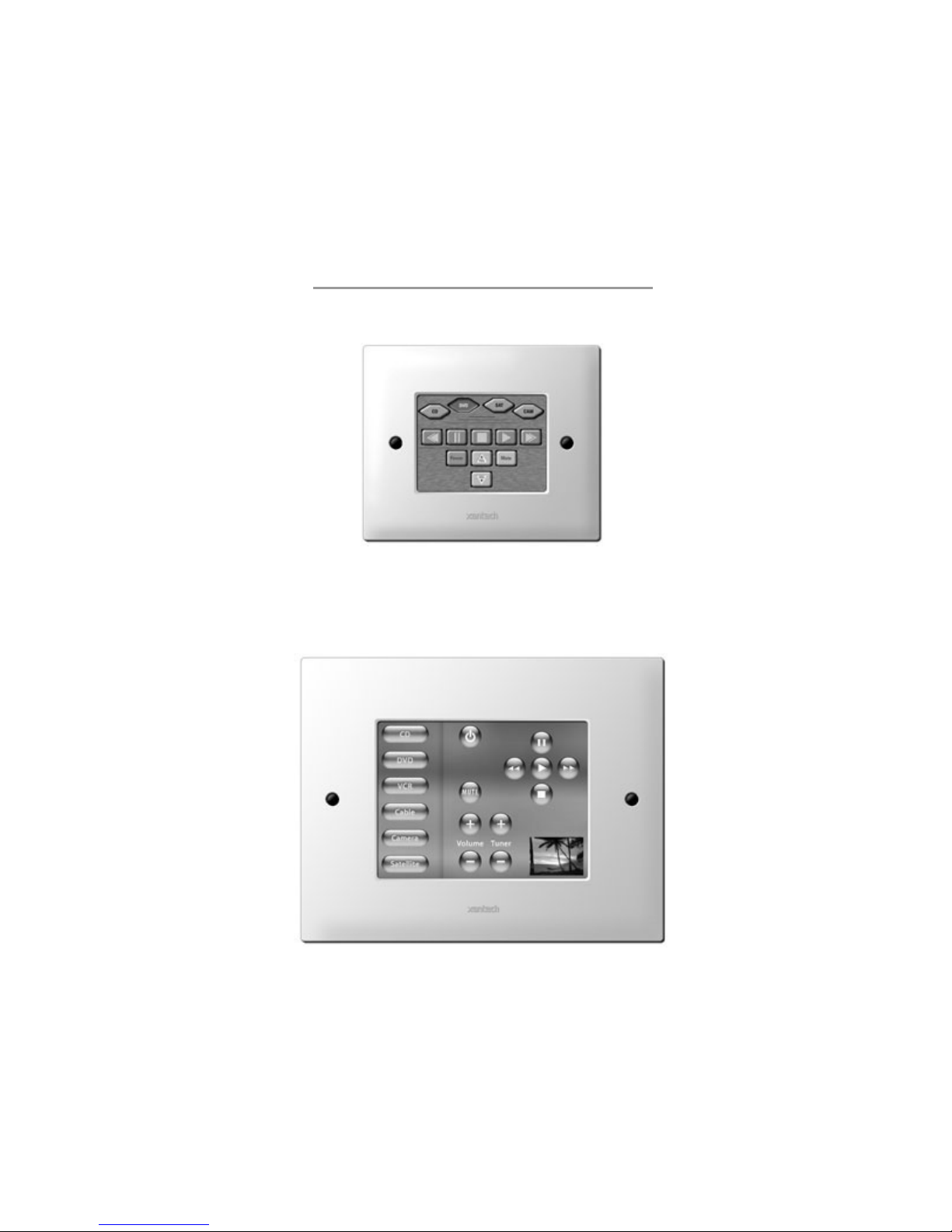
SMARTPAD LCD™
TOUCH-SCREEN PANEL CONTROLLER
Models SPLCD39G, SPLCD57G, SPLCD64G & SPLCD64V
New Feature Addendum Included
SPLCD39G
SPLCD64V
Page 2
Page: 2 SmartPad LCD
SAFETY INSTRUCTIONS - READ BEFORE OPERATING EQUIPMENT
CAUTION: TO REDUCE THE RISK OF ELECTRIC SHOCK,
DO NOT REMOVE COVER (OR BACK)
NO USER-SERVICEABLE PARTS INSIDE
REFER SERVICING TO QUALIFIED SERVICE PERSONNEL
The lightning flash with arrowhead symbol, within an equilateral triangle, is intended to alert
the user to the presence of un-insulated “dangerous voltage” within the product’s enclosure
that may be of sufficient magnitude to constitute a risk of electric shock to persons.
The exclamation point within an equilateral triangle is intended to alert the user to the
presence of important operating and maintenance (servicing) instructions in the literature
accompanying the appliance.
WARNING
TO REDUCE THE RISK OF FIRE OR ELECTRIC SHOCK, DO NOT EXPOSE
THIS APPLIANCE TO RAIN OR MOISTURE.
This product was designed and manufactured to meet strict quality and safety standards. There are, however,
some installation and operation precautions, which you should be particularly aware of.
1. Read Instructions – All the saf ety and operating ins tructions s hould be read bef ore the appliance is operated.
2. Retain Instructions – The safety and oper ating instructions should be retained for future reference.
3. Heed Warnings – All warnings on the appliance and in the operating instructions should be adhered to.
4. Follow Instructions – All operating and use instructions should be followed.
5. Water and Moisture – The appliance should not be used near water – for example, near a bathtub, washbowl, kitchen sink, laundry
tub, in a wet bas ement, or near a s wimming pool, etc .
6. Carts and Stands – The appliance should be used only with a cart or stand that is recommended by the manufacturer. An appliance
and c art combinat ion should be moved with c are. Quick stops, excess ive force, and uneven surfaces may cause the appliance and
cart combination to overturn.
7. Wall or Ceiling Mounting – The appliance should be mounted to a wall or ceiling only as recommended by the manufacturer.
8. Ventilation – The applianc e should be situated s o that its location or position does not interfer e with its proper ventilation. For
example, the appliance should not be situated on a bed, sofa, rug, or similar surf ace t hat may bloc k the ventilation openings; or,
placed in a built-in installation, such as a bookcase or cabinet that may impede the flow of air through the ventilation openings.
9. Heat – The applianc e should be situated away from heat sources such as r adiators , heat registers , s toves, or other applianc es
(including amplifiers) that produce heat.
10. Power Sources – The appliance should be connected to a power supply only of the type described in the operating instructions or as
marked on the applianc e.
11. Grounding or Polarization – Precautions should be taken so that the grounding or polarization means of an appliance is not
defeated.
12. Power-Cord Protection – Power- supply cords should be routed so that they are not likely to be walked on or pinched by items
placed upon or against them, paying particular attention to cords at plugs, convenience receptacles, and the point where they exit from
the appliance.
13. Cleaning – T he appliance should be cleaned only as recommended by the manufac turer.
14. Power Lines – An out door antenna should be loc ated away fr om the power lines.
15. Nonuse Periods – The power cord of the appliance should be unplugged from the outlet when left unused for a long period of time.
16. Object and Liquid Entry – Care should be taken so that objects do not fall and liquids are not spilled into the enclosure through
openings.
17. Damage Requiring Service – The appliance should be serviced by qualified service personnel when:
A. The Power-supply cord or the plug has been damaged; or
B. Objects have fallen, or liquid has spilled into the appliance; or
C. T he appliance has been expos ed to rain; or
D. T he appliance does not appear to operate normally or exhibits a marked change in performance; or
E. The appliance has been dropped, or the enclosure damaged.
18. Servicing – The us er s hould not attempt to service the appliance beyond that described in the operating ins tructions. All other
servicing should be referred to qualified service personnel.
19. FCC Notice – This device complies with Part 15 of the FCC Rules. Operation is subject to the following two conditions: (1) this device
may not cause har mf ul interferenc e, and (2) this device must acc ept any interf erence r eceived, including interference that may cause
undesired operation.
© 2003 Xantech Corporation
Page 3

SmartPad LCD Page: 3
TABLE OF CONTENTS
SAFETY INSTRUCTIONS - READ BEFORE OPERATING EQUIPMENT .........................................................2
TABLE OF CONTENTS............................................................................................................................................3
SECTION 1: GENERAL INFORMATION & FEATURES........................................................... 6
GENERAL INFORMATION.....................................................................................................................................6
OPTIONAL ACCESSORIES: ..................................................................................................................... 6
SYSTEM OVERVIEW...............................................................................................................................................7
SMARTPAD LCD FEATURES.....................................................................................................................................8
SMARTPAD LCD PANEL AND FEATURE DESCRIPTIONS...................................................................................9
SPLCD FRONT PANEL FEATURES AND CONNECTIONS:....................................................................... 10
SPLCD REAR PANEL FEATURES AND CONNECTIONS:......................................................................... 11
SECTION 2: INSTALLATION & CONNECTIONS.................................................................... 13
INSTALLATION......................................................................................................................................................13
BACK BOX MOUNTING INSTRUCTIONS................................................................................................ 13
SPLCD POWER SUPPLY AND INPUT/OUTPUT WIRING INSTRUCTIONS ................................................. 15
Power Supply & Standard Xantech IR Output Bus Wiring:.....................................................................15
External IR Input Wiring:.......................................................................................................................16
MRC Controller and Expansion Port Wiring:..........................................................................................17
Serial RS422/232 Port Wiring:...............................................................................................................18
IR In Zone: ............................................................................................................................................18
INSTALLING SPLCD INTO BACK-BOX................................................................................................ 19
SECTION 3: MAINTENANCE & CALIBRATION..................................................................... 20
CALIBRATION........................................................................................................................................................20
TOUCH SENSE CALIBRATION .............................................................................................................. 20
MAINTENANCE...................................................................................................................................................... 20
CLEANING .......................................................................................................................................... 20
SECTION 4: PROGRAMMING THE SMARTPAD LCD™....................................................... 21
INSTALLING AND CONFIGURING THE DRAGSPLCD SOFTWARE...............................................................21
COMPUTER REQUIREMENTS (MINIMUM) ............................................................................................. 21
INCLUDED HARDWARE & SOFTWARE ITEMS....................................................................................... 21
CONNECTING THE SMARTPAD LCD™ TO THE PC.............................................................................. 21
DB9 Serial Connection...........................................................................................................................21
USB Serial Connection ..........................................................................................................................21
SOFTWARE INSTALLATION.................................................................................................................. 21
STARTING SMARTPAD LCD™ DRAGON DROP-IR™ SOFTWARE......................................................... 22
SERIAL PORT SELECTION.................................................................................................................... 22
Configuring USB Port............................................................................................................................22
Selecting the Proper Com Port................................................................................................................22
Changing the Installed Com Port Settings...............................................................................................23
VERIFYING COM PORT COMMUNICATION ........................................................................................ 23
STARTING A PROJECT.........................................................................................................................................23
CREATING THE GRAPHICAL USER INTERFACE (GUI) ................................................................................ 24
CHOOSING A STYLE ........................................................................................................................... 25
Backgrounds..........................................................................................................................................25
BUILDING A PAGE (WORKING WITH GTL’S) ....................................................................................... 25
Placing Source GTL’s ............................................................................................................................25
Placing Function Button GTL’s..............................................................................................................25
Inserting Additional Pages for a Single Source........................................................................................27
© 2003 Xantech Corporation
Page 4

Page: 4 SmartPad LCD
Editing GTL Properties..........................................................................................................................27
Inserting Labels..................................................................................................................................... 28
LEARNING IR COMMANDS (CREATING PALETTE FILES) ................................................................................... 29
BUILT-IN IR CODE LIBRARY............................................................................................................... 29
Testing IR Commands in the IR Library.................................................................................................29
LEARNING IR COMMANDS (XIR2) ...................................................................................................... 30
Finding the Optimal Positioning of the Teaching Remote ....................................................................... 30
Using the Palette Editor ......................................................................................................................... 30
Editing Function Names in the Palette Editor ......................................................................................... 31
Testing IR Commands in the Palette Editor ............................................................................................ 32
CREATING A PALETTE FILE................................................................................................................. 32
EDITING BRAND, COMPONENT, AND FUNCTION LISTS...................................................................... 33
Adding Brands.......................................................................................................................................33
Adding Components and Functions........................................................................................................ 33
GETTING SOURCE COMMANDS FROM THE INTERNET .......................................................................... 33
Xantech.com .........................................................................................................................................33
Remote Central.com (Importing CCF Files and Discrete IR Commands) ................................................ 33
ENTERING RS232 COMMANDS (CREATING RS232 COMMAND PALETTE FILES) ............................................... 35
ENTERING RS232 COMMAND STRINGS ............................................................................................... 35
Using the RS232 Palette Editor.............................................................................................................. 35
Testing RS232 Command Strings...........................................................................................................36
CREATING AN RS232 PALETTE FILE ................................................................................................... 37
PLACING COMMANDS ONTO THE GTL’S (CREATING MACRO’S) ................................................................... 38
SELECTING IR PALETTES FROM THE IR CODE LIBRARY ...................................................................... 38
SELECTING IR PALETTES ....................................................................................................................38
SELECTING RS232 COMMAND PALETTES............................................................................................ 38
ASSOCIATING COMMANDS TO GTL’S (DRAG AND DROP COMMANDS) ............................................... 38
Programming Sequences (Macros)......................................................................................................... 38
Timed Delays ........................................................................................................................................ 39
Repeat Commands.................................................................................................................................39
EDITING COMMANDS (IN THE MACRO COMMAND LIST WINDOW) ......................................................39
Delete.................................................................................................................................................... 39
Testing Commands Placed on the Virtual SPLCD.................................................................................. 39
TRANSFERRING THE PROJECT ........................................................................................................................ 40
SECTION 5: ADVANCED PROGRAMMING............................................................................. 41
RC68+ IR CODE TRIGGERED SEQUENCER..................................................................................................... 41
PROGRAMMING RC68+ TRIGGERED SEQUENCES ................................................................................ 41
TEACHING RC68+ TRIGGER COMMANDS TO A UNIVERSAL REMOTE ...................................................42
PROGRAMMING THE URC-2B/P FOR USE WITH SPLCD RC68+ TRIGGERED SEQUENCES ................... 42
RS232 INPUT TRANSLATOR................................................................................................................................43
PROGRAMMING IR COMMANDS AND SEQUENCES ............................................................................... 44
Selecting IR Palettes from the IR Code Library...................................................................................... 44
Selecting IR Palettes.............................................................................................................................. 44
Associating RS232 Commands with IR Control Codes........................................................................... 44
Testing Commands in the RS2322 Input Translator................................................................................ 45
SENSE TRIGGER MACRO’S ................................................................................................................................. 45
PROGRAMMING OF SENSE INPUT ......................................................................................................... 45
INTELLIGENT POWER MANAGEMENT................................................................................................... 45
ASSIGNING BANK TRACK CODES TO SOURCE GTL’S ................................................................................. 46
FIRMWARE UPGRADES....................................................................................................................................... 47
DOWNLOADING FIRMWARE FILES FROM THE WEB.............................................................................. 47
FIRMWARE UPGRADE..........................................................................................................................48
SECTION 6: OPTIONS SETTINGS ............................................................................................. 49
© 2003 Xantech Corporation
Page 5

SmartPad LCD Page: 5
RC68 CODE GROUP...............................................................................................................................................49
BANK TRACK CODE GROUP...............................................................................................................................50
STATUS LED SETTINGS ....................................................................................................................................... 50
STATUS LINE ROLE SETTING ............................................................................................................................ 50
INPUT ................................................................................................................................................. 50
OUTPUT ........................................................................................................................................... 51
BACKLIGHT CONTROL....................................................................................................................................... 51
DISPLAY ORIENTATION...................................................................................................................................... 51
UP ...................................................................................................................................................... 51
DOWN ................................................................................................................................................ 51
RS232 SETTINGS .................................................................................................................................................... 52
Baud Rate, Data Bits, Stop Bits amd Parity Settings................................................................................52
Process RS232 Input ..............................................................................................................................52
SECTION 7: APPENDIX............................................................................................................... 53
INTERFACING SPLCD WITH MRC44 & MRC88 (IR CONTROL).........................................................................53
PROGRAMMING SPLCD FOR USE WITH MRC44 (ZONE CONTROL)...................................................... 53
PROGRAMMING SPLCD FOR USE WITH MRC88 (ZONE CONTROL)...................................................... 54
SMARTPAD LCD 6.4” VIDEO: VIDEO CONNECTION & PROGRAMMING......................................................56
TRANSPARENT BUTTON OVERLAY: FEATURES & PROGRAMMING .......................................................57
MRC88 EMULATION MODE: FEATURE DESCRIPTION & PROGRAMMING............................................. 60
MRC88 OBJECT PROGRAMMING: ADDING VOLUME BAR, STATUS BAR ETC…....................................62
CONFIGURING SPLCD IN DRAGON DROP-IR SPLCD: ........................................................................ 63
IMPORTING CUSTOM BACKGROUNDS: ..........................................................................................................64
© 2003 Xantech Corporation
Page 6

Page: 6 SmartPad LCD
Section 1: General Information & Features
GENERAL INFORMATION
The SmartPad LCD series of touch-screen panels is Xantech’s latest generation of the SmartPad Keypad.
The SmartPad LCD series consists of four, interactiv e, touch-screen panel keypads – a 3.9”, a 5.7” and a 6.4”
diagonal color graphic keypad as well as a 6.4” diagonal video keypad. All functionality and screen graphics
are fully programmable using Dragon Drop-IR™ software. The programming interface is via the RS232 or USB
ports located conveniently behind the detachable faceplate on the front of the unit. All Keypads come with a
built-in extensive IR code library as well as the ability to learn IR codes via the Learning Eye located on front of
the unit.
As with the previous models of SmartPad keypads, these new touch-screen panel keypads are designed to be
stand-alone controllers with the ability to output IR commands onto the standard Xantech four-wire IR bus as
well as receive (and pass-through) IR commands via the built-in IR receiver. These new touch-screen panels
also have the ability to receive and transmit RS232 commands for a wide range of control options. This keypad
is also directly compatible with Xantech’s MRC88 products for seamless integration with the Whole-house
Audio Video Entertainment system.
The SmartPad LCD™ Touch-Screen Panel Keypad includes the following components:
• One SmartPad LCD Touch-Screen Panel
• One DB9 RS232 programming cable to connect (Part No. 05913410)
• One USB programming cable
• One front panel designer Bezel (white)
• Keypad Installation Kit which includes the keypad panel back-box enclosure, an installation template (Part
No. 09590255), 4 back-box mounting clips and touch-panel mounting screws
• CD-ROM Disc contains the Dragon Drop-IR software (Part No. 03900785-01)
• SmartPad LCD™ Installation Instructions (Part No. 08901480)
• Two-4 conductor WECO connector plugs (Part No. 05997400)
• One-2 conductor WECO connector plug
• 4 Keypad jumpers (for Zone Termination, Keypad Address and IR Sensor Enable)
Optional Accessories:
• Optional front panel Designer Bezels:
- Brown
- Black
- Almond
- Bronze
- Gold
• RS422232 Converter (used for bi-directional RS232 communication between SmartPad LCD and other
RS232 devices
• External IR Receivers
480-00 Dinky Link™ Series IR Receivers
490-90 Plasma Friendly Micro Link™ Series IR Receivers
780-90 Plasma Friendly J-Box Series IR Receiver
291 Series Hidden Link™ IR Receiv ers
Note: For a complete list of accessories and Part No.’s, please see the Appendix in the Main SPLCD manual
© 2003 Xantech Corporation
Page 7
SmartPad LCD Page: 7
SYSTEM OVERVIEW
The SmartPad LCD is a complete control system in a single box – meaning, no extra controller box is
necessary. Simply connecting a power supply and connecting the SmartPad LCD outputs to any standard
Xantech IR bus, makes a complete IR Repeater System. By adding the optional RS422/232 converter, you now
can literally control almost any Audio Video or Home Automation component. The SPLCD is also directly
compatible with the MRC-88 Whole-house Audio Video Entertainment System.
SmartPad LCD is easily programmed with DragonDrop-IR Software via an RS232 or USB Port (Program cables
and software included). DragSPLCD is used to graphically design your screens and assign IR and/or RS232
Macros. An internal IR Library is also included for ease of programming.
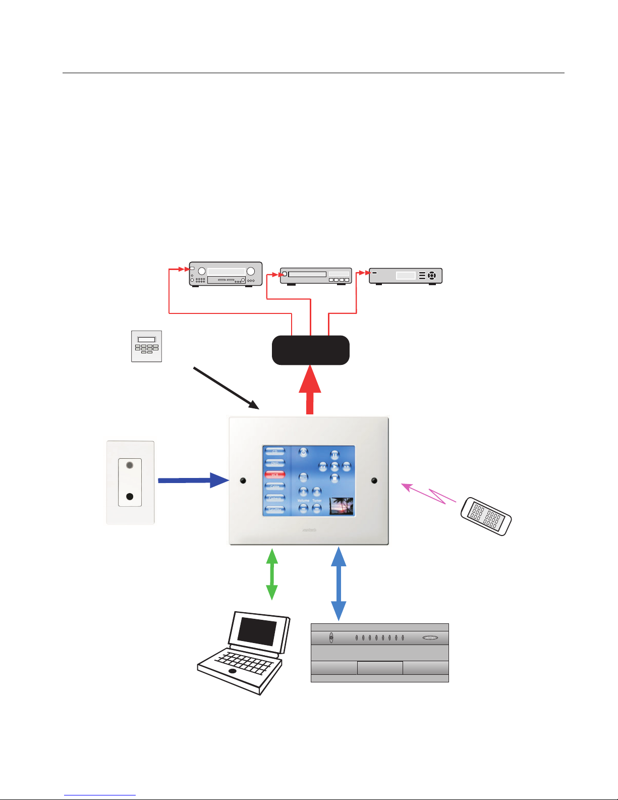
The SmartPad LCD can be wired into numerous simultaneous application configurations such as outlined below
in Figure 1.
Alarm Keypad
AV Receiver
Sense Trigger
Input for Macro
Event Activation
VCR
IR Connecting BlockIR Connecting Block
Satellite Receiver
External IR Bus
Input
Plasma-Friendly
IR Receiver
Bi-Directional
RS422/232 Control
over CAT5
PC, Lighting Control,
HVAC or other RS232
controlled device
Xantech IR Bus
Built In IR
Receiver
Direct RS485
Control of MRC88
over CAT5
MRC88
34
POWER
1
2
5
7
8
6
EIGHT ZONE - EIGHT SOURCE AUDIO/VIDEO CONTROLLER/AMPLIFIER
Hand Held
Remote
© 2003 Xantech Corporation
Figure 1 - System Block Diagram
Page 8

Page: 8 SmartPad LCD
SmartPad LCD FEATURES
LCD Touch Screen Interface: Allows for use of GTL’s (Graphical Touch Link). Colorful graphical
representation of functional buttons for touch control of IR and RS232 controlled devices
Upper and Lower Viewing Angles: Software Programmable for exact viewing placement
Programmable Backlight Control: Selectable Time-Out for LCD backlight
Standard Xantech IR Bus Output: Allows for easy interface to existing IR networks
Internal IR Code Library: Built in IR Code Library. Contains all Major Brand Component IR commands. No
need to ‘learn’ commands.
IR Learning: IR commands can be learned from external hand-held remotes through the SmartPad LCD’s
built-in IR learning eye to add to the SPLCD’s built-in IR code library.
Macros: can be built using IR, RS232, repeat or delay commands and associated with a specific button or
event triggered by a keypad button press, an RC68+ IR code, an MRC88 compatible keypad
command, control sense status, or by RS232. Up to 40 IR commands can be issued in a single
Macro.
IR Receiver: Broad-band IR Receiver for pass through of IR commands from Hand-Held IR Remotes
TalkBack / Status LED: LED indicates presence of IR and/or programmable STATUS indication of Zone or
other user defined power on/off indicator.
RC68+ IR Trigger Sequencer: Trigger IR and/or RS232 Macros via RC68+ IR command received at the
built-in IR Receiver
Status Input: Trigger IR and/or RS232 Macros with a voltage between 5-30VDC
Status Output: Send a 12VDC output voltage to trigger the on/off state of another device or indicator
Serial IO: RS232 control over an RS422 line for RS232 control of remotely located RS232 controlled
devices (Require optional RS422232 adapter).
MRC88 Plug-N-Play: Direct connect to standard Keypad Input of MRC88CTL for full zone control
RS232 Com/USB Com Programming Ports: Communication Programming Ports located on the front
panel of the SPLCD under the bezel, used to program the system using Dragon Drop-IR™
Software
Emitter Output: Local Emitter port on rear of SPLCD
Full Motion Video Input (SPLCD64V only): NTSC/PAL composite video input for full motion video display
on PIP display or full screen
Firmware Upgradeable for ‘Future Proof’ Technology: Upgradeable via RS232 Com Port or USB
programming. Firmware upgrades available for easy download by following LINK’s within Dragon
Drop-IR Software
© 2003 Xantech Corporation
Page 9
SmartPad LCD Page: 9
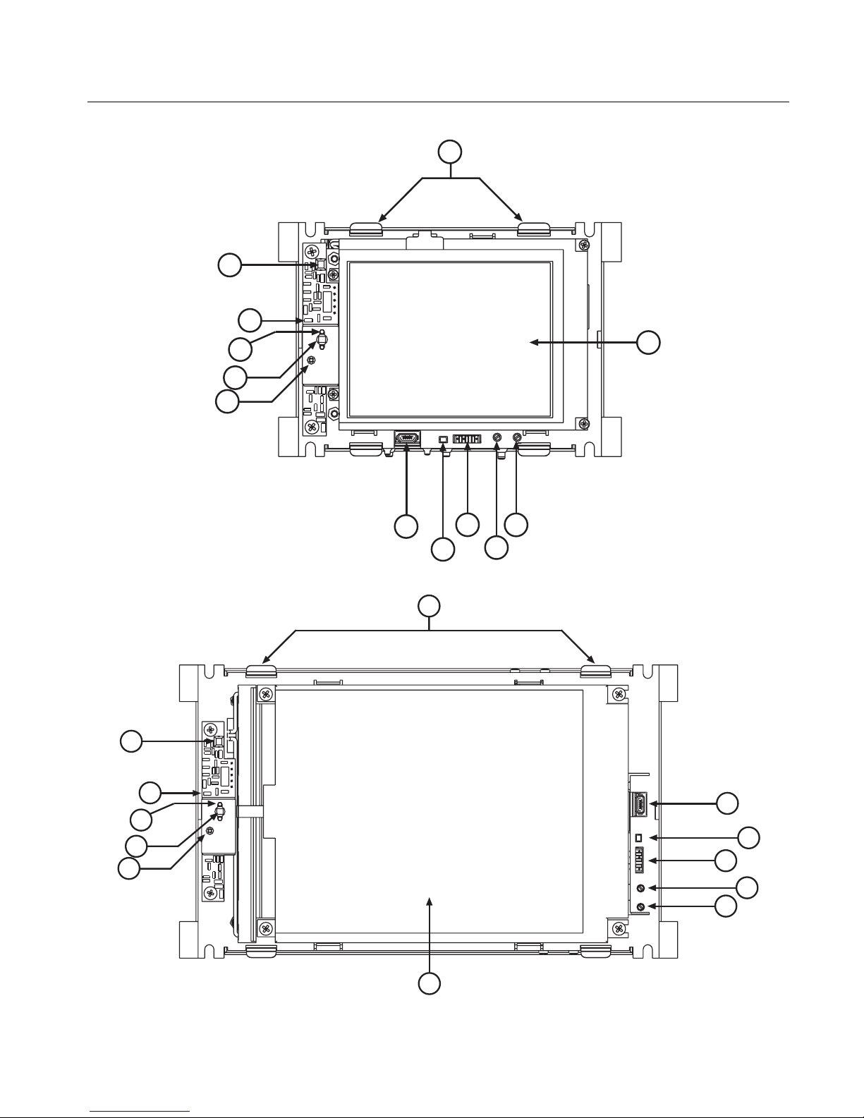
SmartPad LCD PANEL AND FEATURE DESCRIPTIONS
12
5
6
3
2
4
1
9
7
8
10
11
Figure 2a – SmartPad LCD™ Model SPLCD39G – Front Panel Features and Functions
12
5
6
3
2
4
9
8
7
10
11
Figure 2b – SmartPad LCD™ Model SPLCD57G – Front Panel Features and Functions
© 2003 Xantech Corporation
1
Page 10
Page: 10 SmartPad LCD
10
5
6
3
8
7
9
1
2
4
12
Figure 2c – SmartPad LCD™ Model SPLCD64G & SPLCD64V– Front Panel Features and Functions
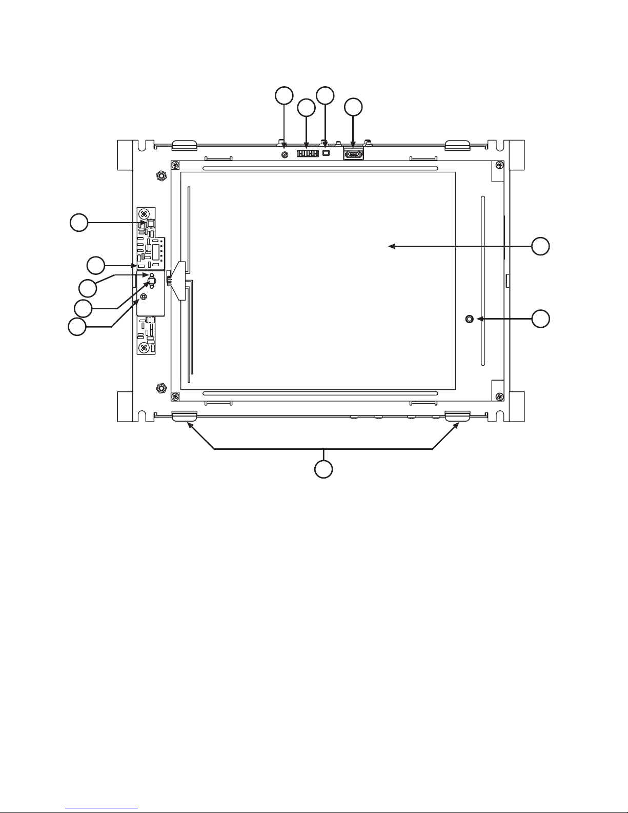
SPLCD FRONT PANEL FEATURES AND CONNECTIONS:
1. LCD Touch Screen. Displays Graphical Touch Links (GTL’s) for touch initiation of IR and RS232
Macro’s.
2. IR Receiver. Receiv es IR from hand-held remotes to control IR dev ices connected to the SPLCD
panel and to trigger IR and/or RS232 macros when RC68+ IR commands are received. WideBandwidth IR Receiver. Excepts IR with carrier frequencies within the range of 32kHz and 75kHz.
3. IR Talkback and Status LED Indicator.
• Flashing LED – Indicates presence of IR at internal IR receiver or External IR input
• Steady Green LED – Indicates Status Line is High either Input or Output
• Blinking LED (During Project Download)– Indicates a Base Unit Transfer is in progress
4. IR Sensitivity Adjustment. Carefully adjust for background light level to prevent false triggering of the
IR circuits. Slowly turn counter-clockwise to reduce sensitivity.
11
© 2003 Xantech Corporation
Page 11
SmartPad LCD Page: 11
5. IR Learning Eye. The IR Eye on the MRC88 Controller front panel allows teaching IR Codes to Dragon
Drop-IR™ via the Control Amp when connected to a PC ‘s com port.
6. IR Learning Eye LED. Brightness indicates strength of Teaching remote to SPLCD IR Learning sensor
7. RS232 Com Port. 3 Pin Header. Used to program the SmartPad LCD from a PC using Dragon Drop-
IR™ Software and for Firmware Upgrades.
8. RESET Button. Depressing button with blunt object will recycle SPLCD to initial POWER ON state
9. USB Com Port. Used to program the SmartPad LCD from a PC using Dragon Drop-IR™ Software and
for Firmware Upgrades.
10. LCD Backlight Adjustment. Adjusts brightness of LCD backlight. Slowly turn counter-clockwise to
reduce brightness.
11. LCD Contrast Control. Adjusts Contrast of SPLCD screen. Slowly turn clockwise to increase contrast
of images on LCD screen.
12. Bezel Mounting Clips (4). Guide clips for mounting Front Bezel onto SPLCD Display
15
13
16
17
21
14
SPLCD
SMARTPAD LCD
GRAPHIC TOUCHPANEL
+12V OUT TO EXPANSION
CONTROLLER EXPANSION
IR OUT
GND
IR IN
ZONE
TERMINATION
+16V IN ONLY
GND
STATUS
IR BUS
CAUTION:
SPLCD ONLY!
DO NOT CONNECT
12V DEVICE
IR BUS
SERIAL
IR RECEIVER ENABLE
+12V OUT
GND
GND
IR IN
IR RECEIVER
1918 20
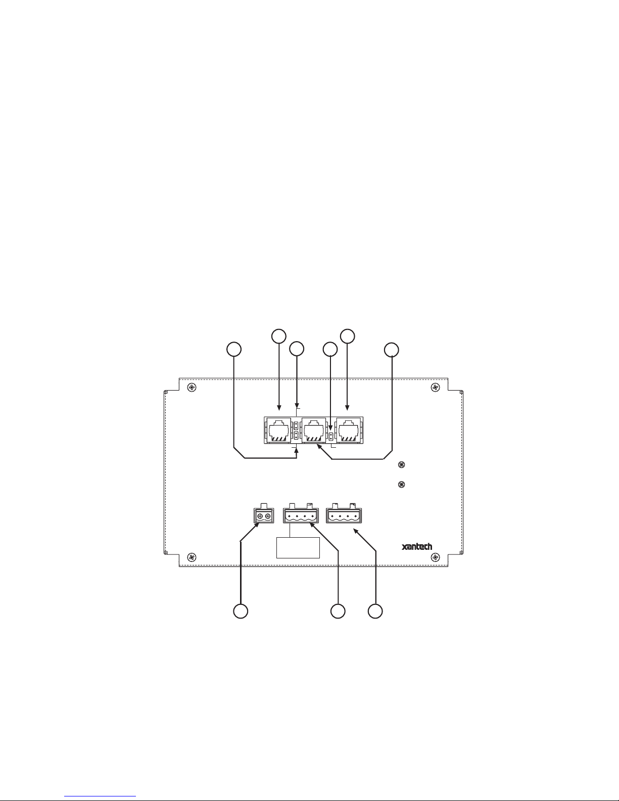
Figure 3 – SmartPad LCD – Rear Panel Connections and Functions
(Model SPLCD57G Displayed)
SPLCD REAR PANEL FEATURES AND CONNECTIONS:
13. Controller Terminal. RJ45 Jack. Connects Keypad to zone keypad input on MRC88 Controller via
CAT5 cable.
14. Expansion Terminal. RJ45 Jack. Allows keypad to be daisy chained to another keypad for multiple
control locations within a zone. Up to 4 keypads are supported per zone.
© 2003 Xantech Corporation
Page 12

Page: 12 SmartPad LCD
15. 12V Out to Expansion: This jumper should be installed when connecting the Expansion port to
another MRC88 Keypad.
16. Zone Termination. Jumper. Do not remove jumper if there is only one keypad in a zone. If there is
more then one keypad in a zone, remove from all but the last keypad in the daisy chain configuration.
17. IR Receiver Enable. Jumper. Enables IR sensor on Keypad. Remove when using an external IR
receiver or if experiencing IR interference from external sources (Plasma, LCD, Fluorescent lights,
Sunlight etc…)
18. IR In-Zone. 2-Terminal WECO style socket - Zone IR out for local ‘In-Zone’ emitter out. Used for IR
control of equipment in the same location as the SPLCD. Output equivalent to that of Xantech Amplified
Connecting blocks. 100mA peak output. Connect directly to Emitter or to Xantech Connecting Blocks
(789-44 or 791-44).
19. Power Input & IR Output Terminal:
a. +16VDC: For connection from 16VDC SPLCD Power Supply (Models SPLCDPS1 &
SPLCDPS4)
b. GND: Power Supply and IR GND connection
c. STATUS: 5-30VDC Status Input for Macro Trigger or LED power Indication from remote
device or 12VDC STATUS output from SPLCD to remote device. (Use Dragon Drop-
IR to configure terminal as a Status Input or Status Output).
d. IR BUS: IR Output from SPLCD to be connected to Xantech Connecting Blocks (i.e. 789-44,
791-44, CB60 etc.)
20. External IR Input. 4-Terminal WECO style socket – Allows connection of other Xantech IR Receivers
and/or Keypads to be used in conjunction with the SPLCD. RC68+ commands received here can
trigger internal IR and/or RS232 Macro’s to be outputted on IR BUS terminal and/or Serial RJ45
terminal.
21. SERIAL: This is a bi-directional RS422 Serial port that can be run up to 4000ft (1.2KM) to communicate
with a remote RS232 device. This uses a standard CAT5 cable terminated in RJ45 connectors on both
sides. The RS422232 converter and a 12VDC Power Supply (both sold separately) are required
© 2003 Xantech Corporation
Page 13
SmartPad LCD Page: 13
Section 2: Installation & Connections
INSTALLATION
BACK BOX MOUNTING INSTRUCTIONS
All four models of the SPLCD Touch Panel are to be mounted into its corresponding junction box (included). No
screws are necessary for affixing this junction box into drywall, lath & plaster, button board or other surfaces
covering a hollow wall. This wall needs to be at least 3.5” (8.9cm) deep.
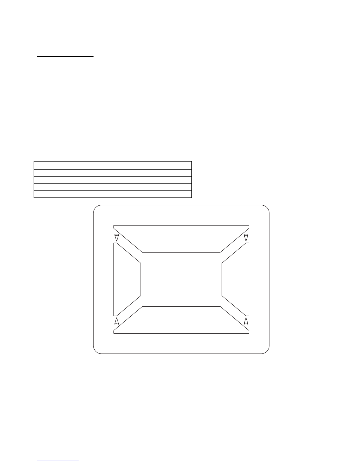
A Mounting Template Wall-Cutout is included for precise hole dimensions. There are three models, one for
each display size (3.9”, 5.7” and 6.4”).
NOTE: The mounting hole size is critical as there is a +0.00” inch tolerance for this cutout. It is imperative that
the provided mounting template be used to assure proper hole size. Check the table below to be sure you are
using the proper Mounting Wall-Cutout Template.
SPLCD Model # Mounting Template Part No.
SPLCD39G 08187158
SPLCD57G 08187156
SPLCD64G 08187157
SPLCD64V 08187157
CUT OUT
CUT
OUT
CUT
OUT
CUT OUT
Figure 4 – Back Box Mounting Wall-Cutout Template
Please follow the instructions that follow closely:
1. Place the mounting template on the wall as shown in Figure 4 above.
2. Make sure the Template is level and gently secure to the wall using a hammer
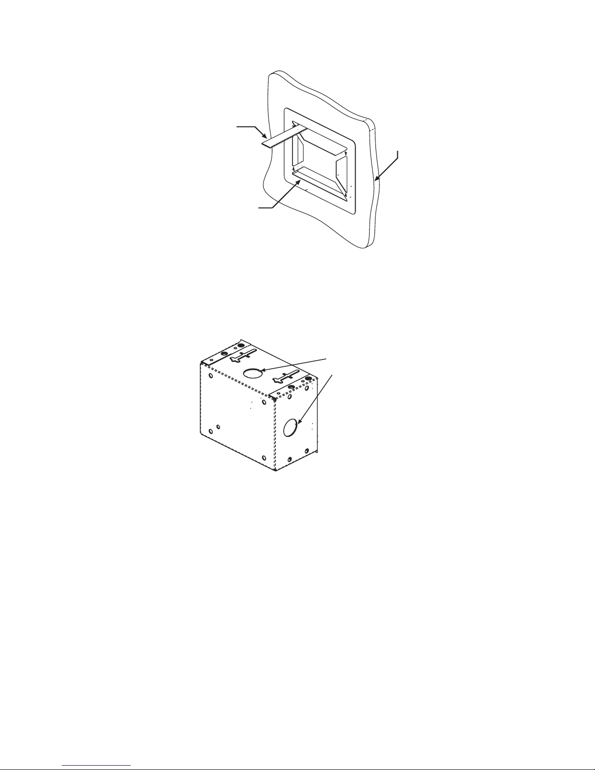
3. Using a hole saw or other cutting tool, carefully cut along the inner guide lines of the Mounting
Template as shown in Figure 5 below.
© 2003 Xantech Corporation
Page 14
Page: 14 SmartPad LCD
CUTTING TOOL
WALL
CUT-OUT WALL TEMPLATE
Figure 5 – Cutting Mounting Hole
4. After the four areas are cut out, remove the Cutting-Hole Template and carefully remove the four areas
that remain attached. Clean the area of any loose pieces still making sure not to enlarge the hole past
the recommended dimensions.
5. Remove the appropriate hole-knockouts on the back box to allow for wiring of the SPLCD display.
Cable Access
Punch-Outs
Figure 6 – Back Box Cable Access Point (Back-Box Rear View)
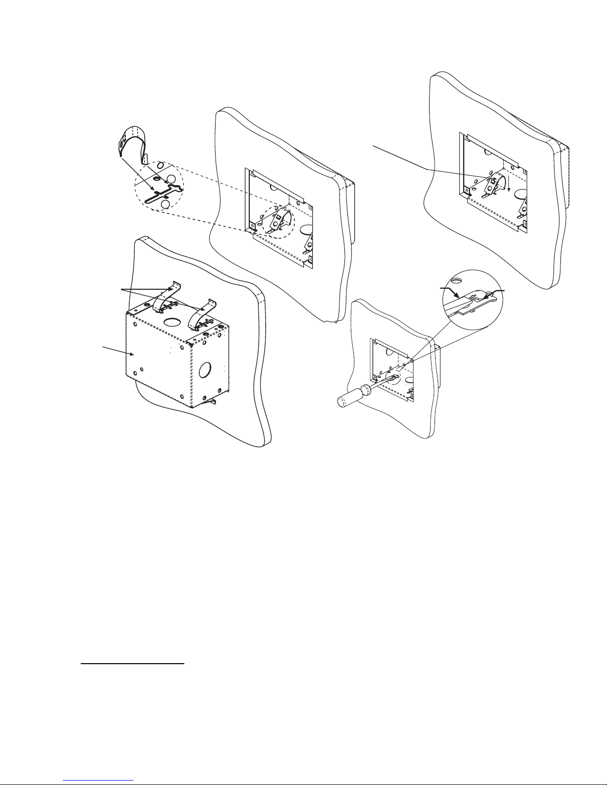
6. Bring cable through wall and desired punch-out access hole in the Back Box.
7. Insert Back Box into the wall and carefully hold in evenly place as to not allow it to fall into the wall.
8. Insert the Mounting Clip into SLOT ‘A’ and ‘B’ as shown in Detail ‘A’ of Figure 7.
9. Push the Clip with your thumb in the direction of the arrow. The back of the clip should move down into
SLOT ‘B’.
Note: If more pressure is needed, use a screw driver as shown in Detail ‘B’ of Figure 7
10. Repeat for all four clips. A rear view of the Back Box with clips installed is shown below.
© 2003 Xantech Corporation
Page 15
SmartPad LCD Page: 15
STEP 9
Push Clip with thumb in direction
STEP 8
of arrow. Back of clip should move
down into SLOT B. If more pressure
is needed, use a screw driver as in
DETAIL B
DETAIL A
STEP 10
MOUNTING
CLIPS
BACK BOX
A
B
Detail B
SCREW DRIVER
WALL
TAB OF CLIP
Figure 7 – Installing Back Box Mounting Clips
SPLCD POWER SUPPLY AND INPUT/OUTPUT WIRING INSTRUCTIONS
The SmartPad LCD can be interfaced in numerous fashions; Standard Xantech IR Bus, RS232, Direct
Connect to MRC88, External IR Input, and Local IR (Emitter Output). The following sections below address
each of these wiring configurations.
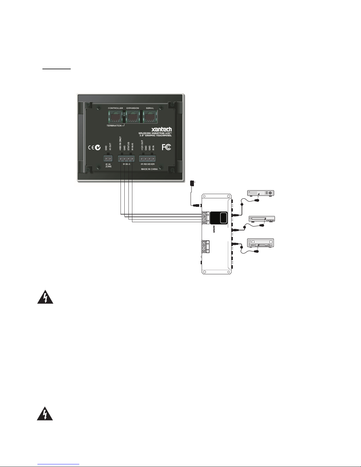
OWER SUPPLY & STANDARD XANTECH IR OUTPUT BUS WIRING:
P
(Figure 3-19)
A 4-Termianl WECO connector is provided with the SPLCD for the +16VDC, GND, STATUS, and IR OUT
connections. For convenience of wiring, it is recommended that the Power Supply and IR Connecting Block
be placed at the same location although this is not required. If placed in the same location, 4-Conductor
18AWG is recommended for ease of wiring.
Power Supply Wiring:
The SmartPad LCD series requires a 16VDC Power Supply (Xantech Model #SPLCDPS1).
This is a 16VDC Power Supply @ 1.5A and is sufficient for providing power for one SPLCD unit.
© 2003 Xantech Corporation
Page 16
Page: 16 SmartPad LCD
Connect the 2.1mm Coaxial plug of the power supply into the 16VDC input of SPLCD Connecting Block
(Model #SPLCDCB10).
IR Wiring:
Wire 4-Conductor 18AWG from the SPLCD’s IR OUT, GND, STATUS (optional) and +16VDC terminals
back to the appropriate terminals of the SPLCD Connecting Block. See Figure 8 for wiring examples.
SPLCDPS1
16VDC Power Supply
(To Un-Switched AC Outlet)
SPLCD-CB
Amplified Connecting Block
16 VDC
Satellite Receiver
283M
Emitter
SPLCD
+16 VDC
RCVR
IR
GND
STATUS
IR IN
SPLCD-CB
AMPLIFIED
CONNECTING BLOCK
®
+12 VDC OUT
GND
STATUS
IR IN
ONLY
EMITTERS
VCR
AV
Receiver
283M
Mouse Emitter
283M
Blink-IR
Emitter
Figure 8 – Power Supply and IR Output Wiring (Model # SPLCD CB Shown)
Caution: Remember, the STATUS output can be either an Input (5-30VDC from remote device) to
trigger a Macro within the SPLCD give LED indication of a unit or Zones power status, or it can be an
OUTPUT (+12VDC from the SPLCD) to trigger some other external device. This is important to note
before STATUS wiring is made between the SPLCD and the other device. DO NOT CONNECT AN
OUTPUT TO ANOTHER DEVICES OUTPUT!
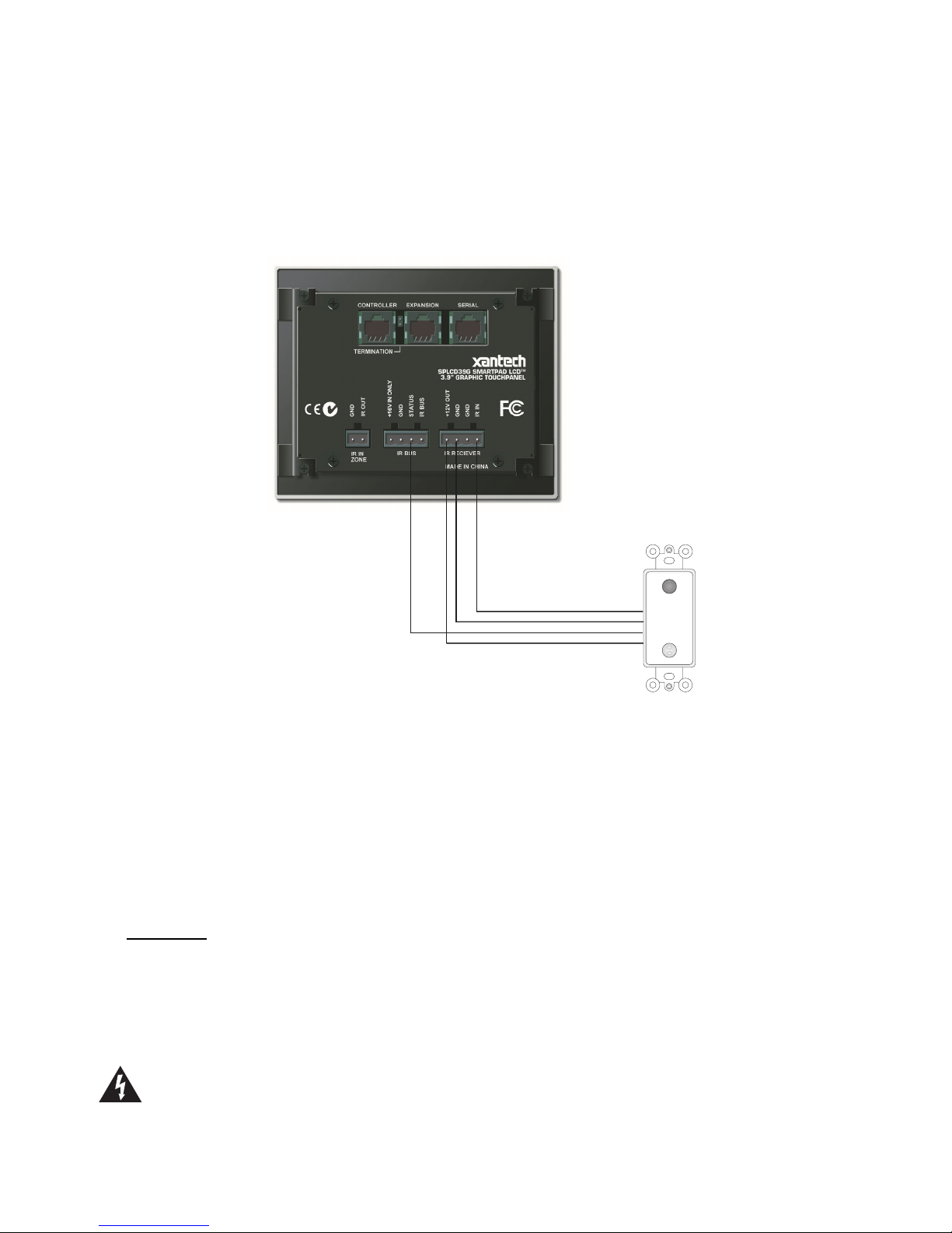
XTERNAL IR INPUT WIRING:
E
(Figure 3 – 20)
A 4-Terminal WECO connector is provided for convenient wiring of external IR Receivers (780-90, 291-10,
490-90, etc…) to the SPLCD display. IR commands received here will be rebroadcast and passed out the
Xantech IR Bus of the SPLCD (Fig. 3 – 19). RC68+ commands received here (of the proper Code Group)
can trigger internal IR or RS232 Macros programmed into the SPLCD display.
• +12VDC Output: This is a voltage regulated +12VDC output signal derived internal to the SPLCD unit
from the 16VDC supply voltage. Use this output to power the external IR Receiver. The 12VDC output
can power a load of up to 100mA maximum (80mA effectiv e load).
Caution: This is a 12VDC OUTPUT only. Do not connect a 12V power source to this point. This is
only an OUTPUT to power an external IR Receiver.
© 2003 Xantech Corporation
Page 17
SmartPad LCD Page: 17
• GND: Both GND terminals are internally connected to the same point and represent Chassis Ground of
the unit. Use either terminal to the GND of the external IR Receiv er.
• IR Input: Connect to IR Output of an IR Receiver such as the 4such as the 490-90, 291-10, 480-80 or
other.
Use 3-Conductor 18-24AWG wire (4-Conductor if using the STATUS line). Gauge varies by wire run
distance. See Figure 9 for wiring examples.
IR OUT
GND
STAT US
+12VDC
780-90
Plasma-Friendly
IR Receiver
Figure 9 – External IR Input Wiring
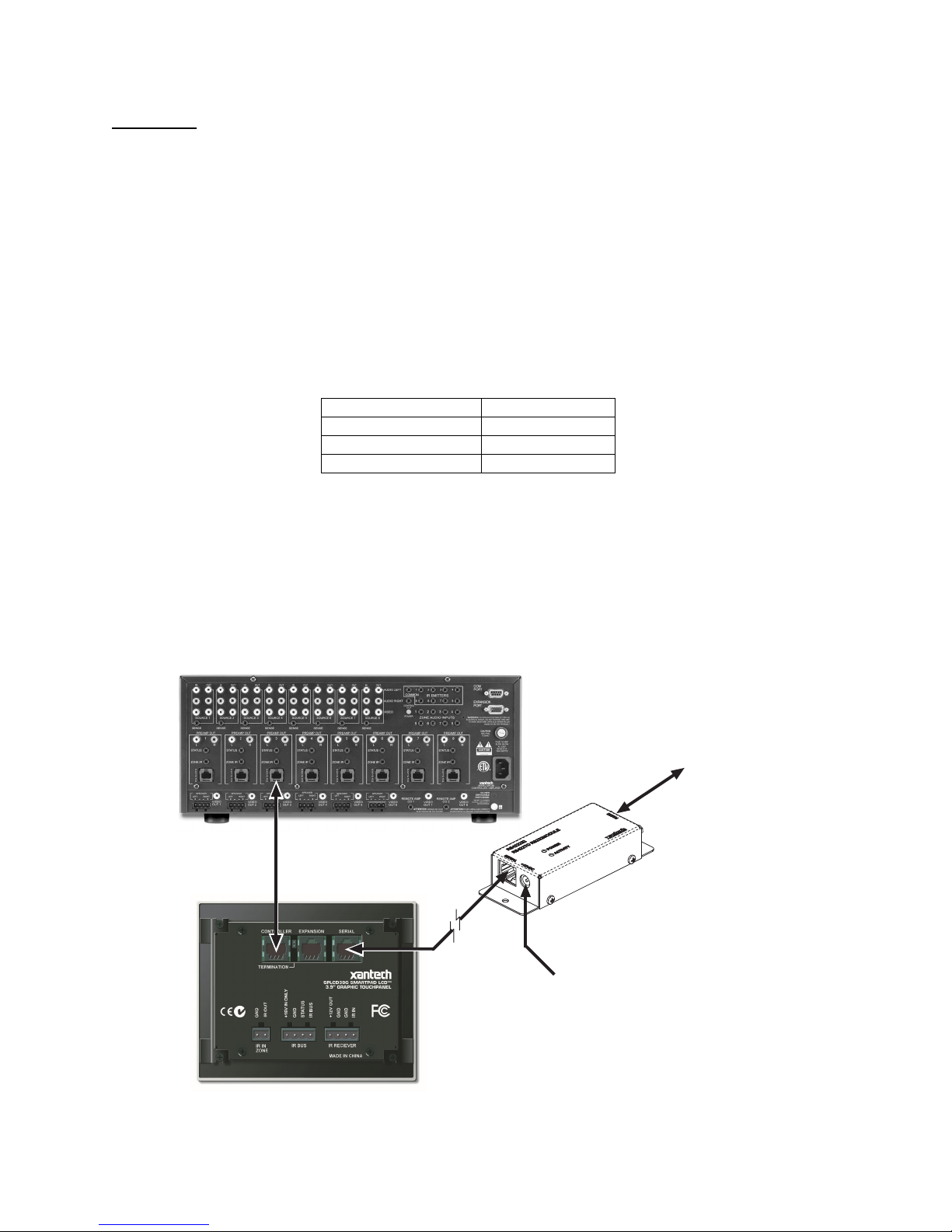
MRC C
ONTROLLER AND EXPANSION PORT WIRING:
(Figure 3 – 13/14)
These RJ45 ports are used for interfacing the SmartPad LCD unit directly to the MRC Controller and/or
Expansion MRC Keypads. The SPLCD can interface to the MRC Products in two fashions via this
connection:
1. Via IR along the dedicated IR lines of the MRC’s CAT5 connection (Pins 4 & 5) (MRC88 & MRC44)
2. Direct to the MRC88 processor via the internal RS485 communication lines (Future Feature)
Controller:
This port is used to connect the SPLCD either directly to the MRC88 Controller or to an existing MRC88
Keypad’s Expansion port. Connect using CAT5 cable terminated at both ends with RJ45 connectors (using
the EIA/TIA 568B standard) from the MRC88 Controller/Amplifier (Zone Keypad Connection located on the
rear of the unit) into the RJ45 connector marked “Controller” on the rear of the SPLCD keypad.
Note: When the SPLCD is the last Keypad connected in line with the MRC88, the Zone Termination
Jumper (Figure 3 – 16) needs to be installed.
Caution:
destroy the MRC Keypad and/or the SPLCD Display! Be sure to test cable for proper connections before
making connections.
Power voltage for the keypad is transmitted along this cable! Incorrect wiring on this cable can
© 2003 Xantech Corporation
Page 18
Page: 18 SmartPad LCD
Expansion:
This port is used to connect the SPLCD to an additional MRC88 Keypad. Connect using CAT5 cable
terminated at both ends with RJ45 connectors (using the EIA/TIA 568B standard) from the EXPANSION
connector (Figure 3 – 14) on the rear of the SPLCD Display into the RJ45 connector marked “Controller” on
the rear of the MRC88 keypad.
Note: The Zone Termination Jumper (Figure 3 – 16) needs to be removed in this configuration and the 12V
Out to Expansion jumper (Figure 3 – 15) needs to be installed.
ERIAL RS422/232 PORT WIRING:
S
(Figure 3 – 21)
This is a bi-directional RS422 port that can be run up to 4000ft. (1.2KM) to communicate with a remote
RS232 device. Use CAT5 cable terminated in RJ45 connectors. The RS422232 converter (sold separately)
and a 12VDC Power Supply are required located at the remote location within 30ft of the RS232 device to
be controlled.
Note: Null Modem Adaptor may be necessary for proper communication. Please consult manufactures
specification of device being controlled.
DB9 Pin Out Function
2
3
5
Rx
Tx
GND
RS422232 DB9 Pin Out
N ZONE:
IR I
(Figure 3 – 18)
To wire local emitters in-the-zone (emitters used to control components in the same general area as the
SmartPad LCD), wire the IR OUT and GND terminals on the rear of the SPLCD Display to the IR (white
stripe) and GND of the emitter cable. To control numerous components in the same area, wire these
terminals to an amplified connecting block (Xantech Model 791-44) using 18-20AW G 2-conductor cable. A
2-conductor screw-type removable connector is provided.
Note: IR In Zone port is an MRC88 feature. This is active only when enabled in the MRC88 DragMRC
Software.
DB9 IO for local Control of RS232
Devices (i.e. Projector, Lighting
Control Systems, PC Control etc.)
CAT5 Wire To
MRC88 or MRC44 Control Input
(MRC88 Full Duplex Communication)
odel RS422232
Xantech M
RS422 to RS232 Convertor
CAT5 Wire
Up to 4000
(Terminate in RJ45)
Requires 12VDC Power Supply
(Xantech Model 781RG)
Figure 10 – Interfacing to MRC and Serial Control
© 2003 Xantech Corporation
Page 19
SmartPad LCD Page: 19
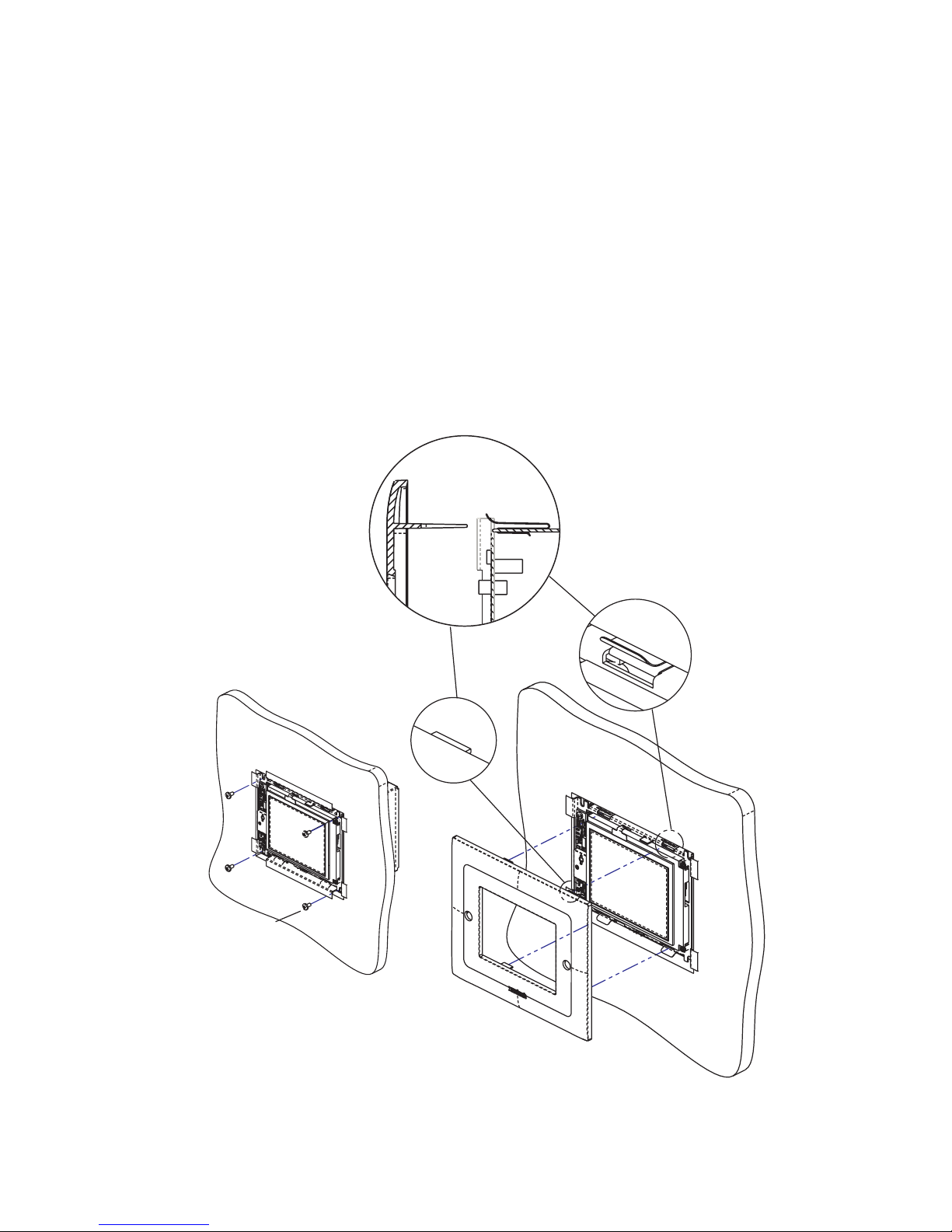
INSTALLING SPLCD INTO BACK-BOX
Note: The SmartPad LCD can be programmed for Upper or Lower viewing angles. Depending upon
which viewing angle the display was programmed for, effects the orientation of the display in the back box.
Displays programmed for Upper viewing angle need to be installed with the IR Receiver PCA located on the
right side and displays programmed for Lower viewing angle need to be installed with the IR Receiver PCA
located on the left side. (see Figures 3a, 3b & 3c)
1. Pull all wires through the wire-access hole in the Back Box leaving slack for strain-relief and connect to
appropriate ports on rear of the SPLCD Display.
2. Insert SPLCD into Back Box oriented according to desired viewing angle so that the unit is flush within
the Back Box.
3. Secure with four 6-32x¼” screws (Part No. 103497). Note: Do not completely tighten screws.
4. Make sure display is level within the box and finish tightening screws. Be sure not to over-tighten.
5. Install front Bezel making sure all four tabs are properly aligned and inserted into their corresponding
Bezel Mounting Clips. (See Figure – 11 Detail A)
6. Push Bezel gently into mounting clips until flush with the wall making sure side tabs go through slots on
metal bracket.
Detail A
Side View
STEP 3
6-32x¼ Screws
MOUNTING CLIP
STEP 5
BEZEL TAB
© 2003 Xantech Corporation
Figure 11 – Installing SPLCD into Back Box
Page 20

Page: 20 SmartPad LCD
Section 3: Maintenance & Calibration
CALIBRATION
TOUCH SENSE CALIBRATION
The accuracy of triggering a Hot-Spot associated to a GTL (Graphical Touch-Link) can be calibrated using
the enclosed Calibration Stylus (Part No. XXXX).
Note: Beta Units will not come with Stylus. Please use and PDA stylus or other similarly sized blunt
pointing device for the following.
To enter Calibration Mode:
1. Power ON the SPLCD and allow to boot
2. W ith the backlight out, press and hold any area of the Touch Screen display with your finger. If the
display is active (i.e. backlight ON), simply press and hold an area without an active GTL.
3. While keeping contact on the screen with your finger, gently depress the RESET button (Figure 3 –
8) of the display with the enclosed stylus.
4. Keep pressure on the screen while the SPLCD is rebooting. After approximately 3 seconds, the
backlight will illuminate.
5. Release the screen and a black ‘dot’ should appear on the side opposite the built in IR Receiver.
6. With the stylus, touch the center of the ‘dot’ and release.
7. Another calibration ‘dot will appear towards the middle of the screen. Again, touch the center of the
‘dot’ and release. One more calibration ‘dot’ will appear. Repeat as above. (There a total of three
calibration points).
After the third calibration point, you can test the accuracy of the calibration. Simply touch anywhere on the
screen and a ‘dot’ will appear in that touched location. If the ‘dot’ appears far from the ‘touch-point’ location,
repeat steps 3 thru 8.
Exiting Calibration Mode:
After 10 seconds of no activ ity, the SPLCD will automatically return to normal operation.
MAINTENANCE
CLEANING
The SPLCD should be cleaned with a non-abrasive cloth such as that used for eye-glass cleaner. No liquid
cleanser is should be used directly on the display. If the unit is powered OFF, gently wipe the face of the
display so no fingerprints or dust can be seen.
If the unit is powered ON (active), simply press and hold an area of the SPLCD Display with no activ e
GTL’s. While holding this area, gently wipe the rest of the display as noted above.
© 2003 Xantech Corporation
Page 21

SmartPad LCD Page: 21
Section 4: Programming the SmartPad LCD™
Programming the SmartPadLCD system is a two-step process:
1. Creating the GUI (Graphical User Interface) Screens.
2. Assigning functions (marcos) to the GTL’s (Graphical Touch Links) to control external devices.
Through Dragon Drop-IR™ Software, both of these tasks are easily performed. The software contains built-in
Style libraries for creating the GUI screens as well as IR-Code libraries for programming each of the GTL’s. This
makes programming the SPLCD a very quick and easy process.
INSTALLING AND CONFIGURING THE DragSPLCD SOFTWARE
COMPUTER REQUIREMENTS (MINIMUM)
• Pentium III 400MHz Processor
• Windows 98/ME/NT/2000/XP
• 60 MB Hard Drive space (you will need more as your keypad libraries expand)
• 64 MB RAM (128 MB preferred)
• Mouse
INCLUDED HARDWARE & SOFTWARE ITEMS
The SmartPad LCD Dragon Drop-IR package includes:
• DragSPLCD CD ROM (Part No.03501030-01)
• DB9 Male to 3 Pin Programming Cable (Part No.03972440). Connects the SPLCD Programming Port
(Figure 2-7) to the DB9 COM PORT on your PC.
• USB Programming (Part No.05913660). Connects the SPLCD USB Programming Port (Figure 2-9) to the
PC’s USB port.
CONNECTING THE SMARTPAD LCD™ TO THE PC
To program the SmartPad LCD™, the unit will need to be connected to a PC.
ERIAL CONNECTION
DB9 S
Connect the supplied DB9 programming cable to your PC serial port and the other end to the 3 pin
connector located under the bezel on the front panel of the SPLCD – Figure 2-7.
USB S
SOFTWARE INSTALLATION
Windows ME/NT/2000/XP
Install the DragSPLCD program onto your hard drive as follows:
ERIAL CONNECTION
Connect the wide end of the included USB cable to the USB port of your PC and the small end to the
connector on the front panel of the SPLCD – Figure 2-9.
NOTE: The USB connection requires a ‘B’ Type connector to interface with the SmartPad LCD™.
Connecting a cable into this port will automatically override any device connected to the RS232 COM
port on the front of the SPLCD.
1. Insert the disc into your computer’s CD-ROM drive. If your driv e has been set for auto run, a Xantech
Welcome Menu will appear. If not, access your CD ROM with Windows Explorer and double click the
file "setup.exe".
2. On the Welcome menu, click NEXT.
© 2003 Xantech Corporation
Page 22

Page: 22 SmartPad LCD
3. Follow the on-screen instructions as the program installs. It takes approximately one to three minutes to
complete, depending on the speed of your machine.
NOTE: For the convenience of the installer, the Dragon Drop-IR™ CD-ROM also contains a complete
set of Application Notes, the Xantech Product Catalog, Factory Learned IR Codes.
STARTING SMARTPAD LCD™ DRAGON DROP-IR™ SOFTWARE
After the successful installation of the software, double-click the Dragon Drop-IR™(SPLCD) icon on your
desktop or:
1. From START menu, choose Programs.
2. Select Xantech and click on the Dragon Drop-IR™(SPLCD) Icon from the menu.
3. The program loads and opens to the following Dragon Drop-IR SmartPad LCD opening screen.
Figure 12 – Dragon Drop-IR(SPLCD) Opening Screen
SERIAL PORT SELECTION
When first launched, the Dragon Drop-IR software scans the serial ports on your computer and will display the
available ports under "Preferences" in the File menu. Unavailable ports will be grayed out.
ONFIGURING USB PORT
C
To configure the USB Port for the first time, complete the following instructions:
1. Connect 16VDC to the SPLCD and allow to completely boot.
2. Start the PC and allow to completely boot.
3. Connect the USB cable from the PC to the USB connector on the front of the SPLCD (Fig 2-9).
4. A New Hardware window should appear on the PC. Follow the instructions that follow and allow
Windows to select the proper driver.
Note: If the Driver is not found, follow the steps below:
4. If the USB Driver is not found, select “Include this location” when Windows prompts you for where
to look for the driver.
5. Click on BROWSE and point windows to C:\Program Files\Xantech\Dragon Drop-IR (SPLCD)\USB
ELECTING THE PROPER COM PORT
S
Normally you would use Com Port 1 (USB will usually appear as COM 3 or above), but if it is already in use, it
will be necessary to use a different one. Select the Com Port as follows:
© 2003 Xantech Corporation
Page 23

SmartPad LCD Page: 23
1. Click Preferences from the File menu or simply press F2 on your keyboard
2. Click on an available port, then OK.
Note: Sometimes when using a USB Port, the PC will set the port to be COM 5 or above. Dragon Drop-IR will
only recognize a Base Unit connected to Com Ports 1 thru 4. To verify (or change) the USB Port to Com Ports 1
thru 4, follow the following instructions.
HANGING THE INSTALLED COM PORT SETTINGS
C
To change the USB Com Port Settings in Windows,
1. Click on the START button located on the Windows Task Bar and Select CONTROL PANEL
2. Select SYSTEM from the list. Note: If using Windows XP™, select CLASSIC View once in CONTROL
PANEL and then select SYSTEM from the list.
3. A SYSTEM PROPERTIES window should appear. Select the HARDWARE TAB and then DEVICE
MANAGER.
4. Click on PORTS and locate the port labeled USB/SERIAL.
5. It should show the COM PORT # in parenthesis next to the listing. If it shows COM 5 or higher, rightclick on USB/SERIAL and select properties from the pop-up menu and then click on the button labeled
ADVANCED.
6. You will now be able to select the proper Com Port from the Drop-Down menu.
.
VERIFYING COM PORT COMMUNICATION
(“Who Am I” Base Unit Version Verification)
Before continuing, it is recommended to v erify proper COM PORT communication between the PC and the
SPLCD. By checking the units Firmware versions and verifying a response from the SmartPad LCD, you will
confirm proper communication and may continue.
1. Power the Unit ON and allow to boot to steady state.
2. Click on the Base Unit Menu and select Who Am I?
3. This should return a listing of the Base Unit Firmware Version .
4. Click Finish to complete the verification
Note: If a message is returned stating: “Communication error. Not able to establish link with MRC Unit” this
could be due to the following:
1. The Unit is not powered ON. Please check the power state of the unit.
2. There is a communication error between the PC and the SPLCD Display. Please verify the DB9 or USB
cable is properly connected to the unit and there are no Com Port conflicts in your PC.
3. You have selected the wrong Com Port. Select the proper setting in the Preference Menu.
STARTING A PROJECT
With the Dragon Drop-IR SmartPAD LCD software open and the COM PORT communication verified proceed
as follows:
1. From the File menu choose “NEW PROJECT” (CTL+N) or choose “OPEN PROJECT” (CTL+O) to
modify an existing project file. You may also use the NEW PROJECT or OPEN PROJECT icons
located on the Tool Bar at the top of the page.
2. In the New Project window, type a file name such as “Master-Bed” and click “SAVE”. The proper file
extension is added automatically.
3. Under the Base Unit menu, select SmartPAD LCD (Setup Environment) and select the proper
environment for the unit to be programmed (i.e. SmartPAD LCD 39G, 57G, 64G, or 64V)
4. The SmartPAD LCD System Window will appear in Graphics Mode as shown below in Figure 13. You
may now begin programming the Graphic Screens.
© 2003 Xantech Corporation
Page 24

Page: 24 SmartPad LCD
New
Project
Open
Project
Save
Grid
ON/OFF
Snap to
Grid
Grid
Color
Grid
Size
Figure 13 – SPLCD Graphic Page Edit Screen
CREATING THE GRAPHICAL USER INTERFACE (GUI)
Through Dragon Drop-IR SmartPAD LCD™ software, you can easily create stylish and intuitive screens in
multiple pages for controlling any IR and/or RS232 Device. Once a project is created and a setup environment
chosen, you are automatically placed in Graphics mode and are now ready to create your GUI (Graphical User
Interface) screen.
Figure 14 – Graphics Screen (Choosing Styles)
© 2003 Xantech Corporation
Page 25

SmartPad LCD Page: 25
CHOOSING A STYLE
Multiple STYLES of Backgrounds, Source Buttons, and Function Buttons are included in a graphics library
within the software. Each STYLE contains its own set of Backgrounds and GTL’s (Graphical Touch Links).
Once a STYLE is selected, only its associated Backgrounds, Source buttons and Function Buttons (GTL’s) will
be available.
NOTE: Future versions of software will allow mixing of styles and the creation or importing of GTL’s.
ACKGROUNDS
B
To choose a style:
1. Make sure you are in Graphics Mode. If not click on the Graphics TAB in the SmartPAD LCD Systems
Window. The GRAPHICS window should now be displayed in the work environment.
2. Click on a STYLE from the list and browse the associated Source and Function GTL’s shown in the list
until a desired style is found.
3. Once a suitable style is found, click on the Backgrounds TAB and then click-&-drag (drag-&-drop!) the
background onto the SmartPAD LCD Systems window grid.
4. Now the Style List will disappear from the Graphics window and only the associated Source and
Function GTL’s of that style will be available.
BUILDING A PAGE (WORKING WITH GTL’S)
GTL’s (Graphical Touch Links) are in plain terms, a graphical button that can pressed to initiate a macro of
IR and/or RS232 commands or to call up a page of additional GTL’s. Source GTL’s will always call up a
page of Function GTL’s and can also have a Macro associated with it if so desired. Function GTL’s can
initiate Macros, call up an additional page of Functions, or do both with the same touch of the GTL. (i.e.
Creating a MENU GTL can initiate a macro to call up a menu screen on a DVD player AND call up an
additional page on the SPLCD screen containing the Cursor GTL buttons to be used when using the DVD
menu.
LACING SOURCE GTL’S
P
1. Once the Background is placed in the Systems window, click on the Sources TAB in the GRAPHICS
window to display the Source buttons associated with that Style.
2. Select a desired Source button (i.e. DVD, SAT, VCR etc..) and in the same manner, drag-and-drop the
Source GTL onto the grid. Note: If a Source button with the proper legend (DVD, SAT, etc..) is not
shown in the list, select the BLANK Source button (no lettering on the GTL) and drag it onto the
Background. BLANK GTL’s may be edited and customized for text and color. Please see the section
Editing GTL Properties below for instructions.
3. Once on the Grid, the GTL can be placed anywhere on the screen. To move the GTL either Click and
Drag to the proper placement, or simply select the GTL with the mouse and then use the arrow keys on
the PC Keyboard to move the GTL around.
4. Repeat Steps 1 & 2 for all desired Source buttons
Note: When a Source GTL is placed on the screen, a new PAGE is automatically inserted for placing
Function GTL’s associated with that Source. If extra pages are needed for that Source, multiple pages can
be inserted for a single source. (Please see Inserting Pages)
LACING FUNCTION BUTTON GTL’S
P
Once a Source page has been inserted, you may now start placing Function Buttons (GTL’s) associated with
that Source onto the Source Page.
1. Click on the Source button located in the SmartPAD LCD Systems window. The Source button should
now appear selected. Note: GTL’s have an UP and DOWN graphic associated with them. UP depicts
the GTL in its non-selected state and the DOWN graphic depicts the GTL in its Selected state. The UP
and DOWN graphics can be edited. Please see Editing GTL Properties for more information on this.
2. Click on the Buttons TAB in the GRAPHICS window. All of the Function Buttons associated with that
Style will be displayed.
3. Select a Button and drag-and-drop it anywhere on the Background in the SmartPAD LCD Systems
window.
© 2003 Xantech Corporation
Page 26

Page: 26 SmartPad LCD
4. If a desired Function Button is not shown in the list, simply select a BLANK button and drag it onto the
Background. As mentioned above, this button can be edited to display the desired text and color you
wish.
Note: You may also place a Text Label onto the Background to describe the function of a button or group
of buttons. This may be desired for Volume or Channel Up/Down controls. For more information on placing
Text Labels on the Background, see the section below entitled Creating Labels.
5. Repeat steps 3 & 4 for all desired Function Buttons for that Source.
Selected
Source
Un- Selected
Source
Function Buttons
for the selected
Source
Figure 15 – Building The GUI Screen
© 2003 Xantech Corporation
Page 27

SmartPad LCD Page: 27
INSERTING ADDITIONAL PAGES FOR A SINGLE SOURCE
Additional blank pages can be inserted for a given source. After a blank page is inserted, it may be populated
with Function Buttons just as in the previous section. This may be useful either when a page becomes full of
commands or for easier operation (i.e. separating the Motion Control buttons and Menu Navigation Buttons of a
DVD Player on separate pages).
The Blank Page is always inserted AFTER the current page you are inserting from.
To insert a page into an existing Source Page, complete the following:
1. Select the Source button of the desired page (if already on the page to be inserted from, go to Step 2).
2. Drag a Function Button onto the existing page to be used as a GO TO PAGE button.
3. Using the PC mouse or other pointing device, right-click on the GTL button you wish to use to navigate
to the next page and select Insert New Page from the drop-down menu.
4. A new page is now inserted and may be filled with additional GTL buttons.
5. You may now insert additional pages in the same manner if so desired or place a GTL button to return
to the previous page.
To Return to the Previous Page, complete the following:
6. Drag a Function Button onto the existing page to be used as a GO TO PAGE button.
7. Using the PC mouse or other pointing device, right-click on the GTL button you wish to use to navigate
to the previous page and select Insert ‘Go To Previous Page’ from the drop-down menu.
Note: This button can also have a macro associated with to perform a function on the actual Source
Component as well as taking the user to the Next Page. For example, a MENU button can be used to call up a
menu on the DVD itself and also bring up a page of MENU Cursor buttons on the SmartPAD LCD panel for the
User to use to navigate through the DVD Menu.
Figure 16 – Inserting a New Page Figure 17 – Returning to Previous Page
E
DITING GTL PROPERTIES
Properties of a GTL button can be edited for Text, Font and color. This allows the user to drag a blank GTL
button on to the GUI page and edited it to their liking. Each GTL has two states a Down and an Up state. Each
of these states can be edited separately to give a unique appearance when either selected or non-selected.
© 2003 Xantech Corporation
Page 28

Page: 28 SmartPad LCD
To edit a GTL proceed as follows:
1. Right-click on the GTL to be edited.
Note: Existing TEXT on a GTL cannot be changed or edited. It is preferred to use a BLANK GTL for
customization.
2. Select Properties from the pop-up menu.
3. Click on the Edit Text / Graphic Tab
4. To Change or Add text to the button, click inside the Caption dialog box and type the desired text.
Note: As previously mentioned above, each GTL button has both an Up and Down image associated with
it. The Up image is how the GTL text appears when not-selected and the Down image is how the GTL text
appears when it is-selected. Both the Font and Color can be edited for each of these states.
5. Select the Font button on either the UP IMAGE or DOWN IMAGE to change the existing Font. The font
font size and font style can all be edited here to any True-Type font currently installed on your PC.
6. After the Font type, Size, and Style are selected, click OK to save the settings.
7. To change the Color of the text, click on the COLOR button and select the desired color from the color
palette and click OK.
8. If both the UP and DOWN images are to be the same, click on either the Copy Right or Copy Left arrow
buttons.
Copy Right: Copies Text Properties from the UP Image to the Down Image
Copy Left: Copies Text Properties from the Down Image to the UP Image
9. To view the changes before exiting the EDIT window, simply click on APPLY. If no more changes are to
be made, click on OK to store the changes.
NSERTING LABELS
I
A Label may be inserted anywhere on the GUI screen to give more detailed description to a GTL or a group of
GTL’s. The label may ev en be used as a Function GTL or even as a Source GTL if so desired.
To insert a Label proceed as follows:
Copy Right
Copy Left
Figure 18 – Edit Text / Graphic TAB
© 2003 Xantech Corporation
Page 29

SmartPad LCD Page: 29
1. Right-Click on any blank area (no GTL’s) in the SmartPAD LCD Systems window.
2. From the Drop-Down menu, select whether this will be a text Label, text-only Source Button, or a text-
only Function Button.
3. Once the label is placed in the Systems window, move the label to its desired location.
4. Right-Click on the label and select Properties from the drop-down menu to edit the text as outlined in
the previous section.
LEARNING IR COMMANDS (Creating Palette Files)
IR Codes from Manufactures remotes of each of the components you wish to control from the SmartPAD LCD
Keypad, may be learned into the Dragon Drop-IR™ software and stored in Palette files for placement onto the
Keypads. In order to do this, the SPLCD must be connected to the PC as outlined above (See Connecting the
SPLCD to the PC).
NOTE: Before starting this section, included in the Dragon Drop-IR SmartPAD LCD™ software, is an extensive
IR Code Library. Before learning IR commands from multiple remotes, check the IR Library to see if your IR
commands for each of the components you wish to control are listed.
NOTE: If you have previously created Palette files in any other versions of Dragon Drop-IR™ Software on your
PC (for programming URC-2’s, MRC88, etc) these files can be Copied and Pasted using W indows Explorer to
the PALETTE folder located under the C:Program Files\Xantech\Dragon Drop-IR (SPLCD) directory on your
PC.
If all of your codes are either located in the IR Code Library or are already learned in palettes, please proceed
to the section entitled Placing Commands onto the GTL’s.
BUILT-IN IR CODE LIBRARY
The Dragon Drop-IR (SPLCD) software has a built-in IR Code Library. This is basically a large database of
Manufactures IR Commands for a whole assortment of components at your disposal. If your manufacture’s
codes are in our database there might not be any need to ‘teach’ IR commands into the system. To check the
Dragon Drop-IR™ Software’s extensiv e IR Code Library, do the following:
1. Make sure a SmartPAD LCD™ Project is open.
2. Click on PALETTE in the Dragon Drop-IR menu bar
3. Select IR Library from the drop-down menu
4. Click on the Component Type (i.e. VCR, DVD etc.) and then the Manufacturer.
5. A list of Command Groups for that manufacturer’s components IR codes will be displayed.
6. You will need to test commands from these different Command Groups to see which one works with
your component. Please see the next section entitled Testing IR Commands in the IR Library.
ESTING IR COMMANDS IN THE IR LIBRARY
T
Once you have located all of the Command Group codes for the appropriate Component/Manufacturer, you will
need to test the commands to see which Command Group is associated with your specific component.
NOTE: To test commands out of the Library, the PC running Dragon Drop-IR software must be connected to
the SmartPAD LCD™ via the RS232 or USB programming port and the IR output of the SPLCD connected to a
Connecting Block as in Figure 8.
1. With the IR Library opened to the specific manufacturers list of Command Groups as outlined above,
click on the first Command Group listed (i.e. Cmd Group1). A list of all of commands associated with
this component should be displayed.
2. Connect an Emitter to the emitter port on the connecting block as in – Figure 8.
3. Place the emitter over the sensor window of the component to test.
4. With the PC still connected to the SPLCD’s programming port, select the “TEST” button located in the
bottom right of the IR Library window. The TEST button should now be outlined in red.
5. Click on the POWER command or other basic function command as listed in the IR Library. The
controlled component should respond to each command sent. (i.e. “Power” turns the source ON or
OFF, “PLAY” plays the content etc.)
6. If a component does not respond to a command, click on another Command Group listed under that
manufacturer and retest.
© 2003 Xantech Corporation
Page 30

Page: 30 SmartPad LCD
7. If the codes for the specified component are present, you are now ready to start creating Macro’s under
the GTL buttons you created in the previous section. Please see the Section entitled Placing
Commands onto the GTL’s. If no working commands can be found in the IR Library, please proceed
to the following section entitled Learning IR Commands.
Figure 19 - Built-In Mfg’s IR Command Library
LEARNING IR COMMANDS (XIR2)
An IR Learning Eye is located on the front panel of the SPLCD and is accessible when the Bezel is removed
(Please see Figures 2a-2c Item #5).
Note: Commands learned through the SPLCD’s front panel learning eye (XIR2 method) are NOT
backwards compatible to other Xantech devices (i.e. MRC44/88, URC-2 etc…). This means, palettes
created in Dragon Drop-IR SPLCD cannot be copied to previous versions of Dragon Drop-IR software.
Palettes created in earlier version of Dragon Drop-IR software (XIR1 method) CAN be copied into the
SPLCD software. (i.e. palettes created in DragMRC, Frag450 or Drag460 software CAN be copied and
used in Dragon Drop-IR SPLCD software).
Note: When learning IR commands through the front panel learning-eye, it is suggested that the environment
be free of any IR interference. This could include Fluorescent or Halogen lighting, sunlight, Plasma or LCD
displays and interference from PC Monitor display.
INDING T HE OPT IM AL POSITIONING OF THE TEACHING REMOTE
F
An IR Strength Indicator LED is also located on the front panel (Figures 2a-2c Item #6) to let the user know
where the optimal position of the teaching remote should be. Before proceeding, please take the proposed
teaching remote and keeping it approximately 1-2 inches from the IR Learning Eye, press any button on the
remote and look at the brightness of the LED (Figure #2a-2c Item #6). Move the Remote slowly up and down
past the learning eye and find the location where the LED is at its brightest. This will be the location to be used
when recording IR commands.
SING THE PALETTE EDITOR
U
© 2003 Xantech Corporation
Page 31

SmartPad LCD Page: 31
NOTE: The Palette Editor for IR Commands is available whether a project is opened or not.
1. From the Component menu, click “PALETTE EDITOR” or hit F3 on your keyboard.
2. Locate and Select (single click) the desired BRAND as shown in Figure 20 (i.e. Sony, Panasonic etc).
A list of Components will appear. (See later section for ‘Adding Brands’.)
3. Locate and Select (single click) the type of COMPONENT as shown in Figure 21 (DVD, SAT etc) (See
later section for ‘Adding Components and Functions’).
4. The Palette Editor will now be open to the “Brand” & “Component” selected. A list of FUNCTIONS for
that type of component will appear as shown in Figure 22. Review the list of Functions on the left hand
side and compare to the source remote. If your function is not displayed or not named appropriately see
the section entitled ‘Editing Function Names in the Palette Editor.
5. Click on the RECORD button in the middle of the Palette Editor. The RECORD button text will turn red.
Dragon is now ready to learn the IR codes for the specific brand/component selected.
Note: Before performing step 6, read steps 6 thru 8 as the RECORD process is a timed function. You
will have 10seconds to perform the process before the system times out.
6. Place the Teaching remote in the optimal position as found above.
7. Select the command the left side of the Palette Editor (i.e. Power, Play, Stop etc.). A message stating
“Waiting For IR” will appear. This process will time-out in 10 seconds.”
8. While continuing to keep the source remote within 1” from the IR learning eye, press and release the
corresponding command button on the source remote. A red symbol (
) will appear to the left of the
selected function indicating that an IR code has been learned.
Note: If you wait longer than ten seconds, a time-out message will appear. Click “Finish” and try again.
If you continue to have problems learning commands, please see the Trouble Shooting section at the
end of this manual.
Note: When teaching commands in this fashion, only a quick tap of the teaching remote is required.
Do not press and hold the button until the message goes away.
9. Repeat steps 6 thru 8 for all of the source functions to be used on the SPLCD Display.
Figure 20
Source BRAND selection in Palette Editor
E
DITING FUNCTION NAMES IN THE PALETTE EDITOR
If a function displayed on the Source Components Remote is not displayed in the function list on the left hand
side of the Palette Editor window, you can either RENAME an existing function or ADD a new function to the
list. Editing function names in the Palette Editor will only effect the Palette File you are currently saving to (i.e.
Making a change to a function under DENON DVD will only appear in DENON DVD).
To Rename an Existing Function
1. Right-click on the function to be renamed.
© 2003 Xantech Corporation
Figure 21
Source COMPONENT selection in Palette Editor
Page 32

Page: 32 SmartPad LCD
2. Choose RENAME from the drop-down menu.
3. Edit the text as desired and press ENTER on your keyboard to save.
To Add a New Function
1. Scroll down to the bottom of the function list on the left hand side of the Palette Editor.
2. Right-click on a blank area of the list and select NEW FUNCTION from the drop-down menu.
3. Enter the name of the new function as you would like it to appear in the list and press ENTER on
your keyboard to save.
ESTING IR COMMANDS IN THE PALETTE EDITOR
T
Be sure corresponding source for the commands to be tested is ON and connected to the SPLCD as described
in Figure 8.
Connect an Emitter to the emitter port on the connecting block as in – Figure 8.
1.
2. Place the emitter over the sensor window of the component to test.
With the PC still connected to the SPLCD’s programming port, select “TEST” in the Palette Editor window. The
3.
TEST button text will turn red.
4. Click on each of the command names one-by-one that need to be tested. A red dot will flash just to the
left of “TEST” as the IR command executes.
5. The controlled component should respond to each command sent.(i.e. “Power” turns the source ON or
OFF, “PLAY” plays the content etc.)
NOTE: Only functions with the
symbol will execute.
6. If a component does not respond to a command, re-learn and re-test the IR command until the
component responds.
7. Repeat steps 1 thru 6 for all commands to be tested.
CREATING A PALETTE FILE
A Palette File is a file of learned commands that is ready to be placed under a GTL for use in the SPLCD Touch
Screen Panel system.
Note: As previously mentioned, Palette files created in Dragon Drop-IR software (XIR2 method) cannot be
shared with previous versions of Dragon Drop-IR™ Software.
1. After Dragon has learned the commands for that Source, select “ADD>>”. The ADD button text will turn
red.
2. Click on a function (i.e. PLAY) to be added to the palette. A “NEW PALETTE” window will open. Type in
a file name (i.e. NAD-CD) and click “SAVE”.
3. “PLAY” will appear in the NAD-CD window with the
symbol.
4. Click on all functions to be added to NAD-CD.PAL
5. Click the “CLOSE” button on Palette Editor. Palette Editor will close. NAD-CD.PAL will be saved to the
hard drive.
7. Repeat steps 1-9 in ‘Using the Palette Editor’ and steps 1-5 in ‘Creating Palettes’ for all components to
be used with the SPLCD Display.
© 2003 Xantech Corporation
Page 33

SmartPad LCD Page: 33
Figure 22: Creating a Palette File
EDITING BRAND, COMPONENT, AND FUNCTION LISTS
If a brand, component, or function is not found in the Palette Editor, each can be added as follows:
DDING BRANDS
A
1. If the brand you need is not already on the list, choose the Component menu and click on “ADD
BRAND”.
2. Type brand name and press enter on the keyboard or click OK.
3. The new name is added and saved to the list.
DDING COM PONENTS AND FUNCT IONS
A
1. If the component you need is not already on the list, choose the Component menu and click on “ADD
REGULAR COMPONENT”.
2. Type the component name (i.e. MP3 Player) and press enter on the keyboard.
3. Type the name of a function associated with this new component in the text box (i.e. POWER or PLAY,
etc…) and press enter on the keyboard to save the new function.
4. Repeat step 3 for all functions required for the new component.
5. Press “ESC” on keyboard to save and exit.
6. New Brands, Components and Functions can now be selected and programmed in Palette Editor.
GETTING SOURCE COMMANDS FROM THE INTERNET
ANTECH.COM
X
There are some IR commands that can be difficult to learn in Dragon. Xantech edits and posts some of these
commands at http://www.xantech.com
located under Support-Downloads-IR Code Libraries. (See website for
listings and download instructions.) A direct link to Xantech.com can be found in the “Links” section of the
Dragon menu bar.
R
EMOTE CENTRAL.COM (IMPORTING CCF FILES AND DISCRETE IR COMMANDS)
Remote Central.com (http://www.remotecentral.com/
) provides an almost unlimited resource of IR commands.
There are two styles of commands that can be imported into the DragMRC software: CCF files and Discrete
Infrared Hex Codes.
Importing CCF Files:
The code files at Remote Central are not directly compatible with Dragon Drop-IR and therefore need to be
converted for use with Xantech software.
NOTE: These files need to be of ProtoEdit Version 1 CCF files.
© 2003 Xantech Corporation
Page 34

Page: 34 SmartPad LCD
1. Click “LINKS” on the DragMRC menu bar.
2. Click on Remote Central Website. Your browser will open and take you to
http://www.remotecentral.com/
3. Click FILES in Remote Central.
4. Click Philips Pronto & Pronto Pro.
5. Scroll and click on desired brand under "Component Configuration Files" (CCF files).
6. Click on component type (CD players, VCR's, etc.).
7. From the list find a Model Number the same as your model or one similar to it. (Even model
numbers considerably different than yours will usually have commands that work).
8. Click on DOWNLOAD (this may take a few seconds), then select Save it to disk, then OK.
9. In the Windows ‘Save As…’ pop-up, Open the CCF folder within the DragMRC88\CCF folder (if not
already open). Click Sav e.
10. In DragMRC, click Import CCF from the File menu.
11. Find the ccf folder in which you saved the file and click on file name.
NOTE: At this point, prior to opening it, you may wish to change the file name (e.g., RCA-DSS,
etc.) for easier recognition later. You may wish to do this in step 13 as well.
12. Click Open. This unzips the file and DRAGMRC88 automatically places it in a folder within the CCF
folder.
13. Click on file name, then on OPEN. At this point, the CCF file is converted to a Dragon format.
14. On pop-up (CCF Importer), type in Brand Name and Component Name (e.g., RCA and DSS).
15. Double click on desired component type on list of converted files on left side of pop-up (e.g.,
DSS.cnv). An asterisk (*) will appear just to the left. Click Import.
16. Click OK for addition to Brand List (if shown) and OK for addition (or merge) to a .bci file.
This completes the file import to the Brand and .bci files in DragMRC.
17. At this point, or at any later date, you can choose additional component types from the CCF file
(e.g., DVD, etc., if listed) by using the CCF Importer again. Simply click Import CCF from the File
menu, double click on desired folder and repeat steps 13 to 16 as necessary.
Importing Discrete IR Hex Codes
Remote Central has a database of discrete power on/off, input codes, sound and picture modes plus
others. You must already be in the Palette Editor window to import these codes.
1. Click “LINKS” on the Dragon Drop-IR SPLCD menu bar.
2. Click on Remote Central Website. Your browser will open and take you to
http://www.remotecentral.com/
3. Click FILES in Remote Central.
4. Click Philips Pronto & Pronto Pro.
5. Scroll down and click on the desired brand under “Discrete Infrared Hex Codes”
6. Click on component type (CD players, VCR's, etc.).
7. From the list find a Model Number the same as your model or one similar to it. (Even model
numbers considerably different than yours will usually have commands that work).
8. Next to the desired command, you should see a box containing the discrete Hex Code. Using your
mouse or keyboard, highlight the entire code for that function and press [CNTRL] + [C] on your
keyboard to copy the selected code to the clipboard.
9. Return to Dragon Drop-IR SPLCD software and in the left-hand side of the Palette Editor, right-click
on the desired function you wish to import the discrete code for.
10. Select Import Discrete IR Code from the drop-down menu.
11. W ith the Cursor in the Paste Discrete IR Code window, press [CNTRL] + [V] on your keyboard to
paste the code under that function and click on IMPORT to save.
12. A RED
will now be displayed to the left of the function indicating the code has been successfully
imported.
13. Repeat steps 8 thru 12 for all commands necessary.
© 2003 Xantech Corporation
Page 35

SmartPad LCD Page: 35
Figure 23: Importing Discrete IR Codes
ENTERING RS232 COMMANDS (Creating RS232 Command Palette Files)
The SmartPAD LCD™ Touch Screen panel can be used to control advanced components such as projectors
and lighting systems directly from the keypad that would normally be controlled via RS232 with exotic
controllers or automated systems.
ENTERING RS232 COMMAND STRINGS
SING THE RS232 PALETTE EDITOR
U
1. From the Component menu, click “RS232 PALETTE EDITOR”.
2. Locate and Select (single click) the desired BRAND as shown in Figure 20 (i.e. Sony, Panasonic etc).
A list of Components will appear. (See previous section for ‘Adding Brands’.)
3. Locate and Select (single click) the type of COMPONENT as shown in Figure 21 (DVD, SAT etc) (See
previous section for ‘Adding Components and Functions’).
4. The Palette Editor will now be open to the “Brand” & “Component” selected. A list of FUNCTIONS for
that type of component will appear as shown in Figure 24. Review the list of Functions on the left hand
side and compare to the source remote. If your function is not displayed or not named appropriately see
the section entitled ‘Editing Function Names in the Palette Editor.
5. Click on the RECORD button in the middle of the Palette Editor. The RECORD button text will turn red.
6. Select the command the left side of the Palette Editor (i.e. Power, Play, Stop etc.). An RS232Command
String Editor window will now appear as shown in Figure 25.
7. Place the cursor in the ASCII (or HEX) row under the column labeled ‘01’ and type in the appropriate
ASCII (or HEX) characters into the cells needed to execute that command.
NOTE: The maximum number of characters that can be entered into a string is 100 characters.
8. Click the button labeled ‘OK’ after the entire string is entered. A DB9 Connector Icon
the left of the selected function indicating that an RS232 Commands String has been entered.
NOTE: A Conversion Utility is included within this window. Entering commands of any format into this
utility will display the character in all other formats (i.e. Decimal, Hex, Binary, and ASCII).
9. Repeat steps 6 thru 8 for all of the source functions to be used with the SPLCD.
will appear to
© 2003 Xantech Corporation
Page 36

Page: 36 SmartPad LCD
Figure 24
RS232 Palette Editor Window
Entering RS232 Command Strings
Figure 25
T
ESTING RS232 COMMAND STRINGS
There are two methods of testing RS232 Command Strings directly from the RS232 Palette Editor: One is
directly out of the PC’s Comport and the second method is through the SPLCD’s RS232 Com Port – Figure 3
Item #21. Using both methods you can control the component or device directly for confirmation of command
string or send the command to an RS232 Utility programming to verify proper output (this is good for Trouble
Shooting purposes or for testing the program without the component or device present).
Using PC TEST:
1. Connect the Com Port of the PC running Dragon Drop-IR SPLCD to the corresponding component
or device of the commands to be tested.
NOTE: A “Null Modem” cable may be necessary for communicating with the Component or Dev ice.
Please check with the Manufacturer to see if this is required.
2. Click on the ‘PC Test’ button in the RS232 Palette Editor.
3. Make sure the RS232 Port Settings are set appropriate for the device connected to (refer to the
mfg’s Instruction Manual of the component or device being tested for the proper communication
settings)
4. Click on the command string to be tested on the left-hand side of the RS232 Palette Editor. Note:
Only commands with the
icon will be able to be tested.
5. The Device or Component connected should respond accordingly. If not, check the command string
entered and port settings in the Test RS232 Settings window. If still having problems see the
Trouble Shooting section to verify RS232 communication.
6. Test all Command Stings in this fashion before placing into a Palette File.
Using SPLCD TEST:
NOTE: The PC running Dragon Drop-IR (SPLCD) needs to connected to the programming port of
the SPLCD Display and communication verified (Base Unit “Who Am I”) before continuing.
1. Connect the Port labeled SERIAL on the rear of the SmartPAD LCD™ Panel – Figure 3 Item #21
to the RS232422 Converter (not included) and then connect the DB9 port of the converter to the
corresponding component or device of the commands to be tested.
NOTE: A “Null Modem” cable may be necessary for communicating with the Component or Device.
Please check with the Manufacturer to see if this is required.
2. Click on the ‘SPLCD Test’ button in the RS232 Palette Editor.
3. Make sure the RS232 Port Settings (Baud Rate, Parity, Data Bits, and Stop Bits) are set
appropriate for the device connected to (refer to the mfg’s Instruction Manual of the component or
© 2003 Xantech Corporation
Page 37

SmartPad LCD Page: 37
device being tested for the proper communication settings). Click on PREFERENCES and verify
the proper Com Port is selected of the PC for communicating with the SPLCD Display)
4. Click on the command string to be tested on the left-hand side of the RS232 Palette Editor. Note:
Only commands with the
icon will be able to be tested.
5. The Device or Component connected should respond accordingly. If not, check the command string
entered and port settings in the Test RS232 Settings window. If still having problems see the
Trouble Shooting section to verify RS232 communication.
6. Test all Command Stings in this fashion before placing into a Palette File.
CREATING AN RS232 PALETTE FILE
A Palette File is a file of learned commands that is ready to be placed onto the SPLCD Display under a GTL
button. These files can be shared with the MRC-88 system as well as all future versions of Dragon Drop-IR™
RS232 capable products. Therefore the procedure of learning and testing these commands and creating the
Palette file for an individual source component only needs to be done once. This file can now be added to a
library of files that you create or download from our web site and used at any time in the future for later projects.
1. After Dragon has learned the commands for that Source, select “ADD>>”. The ADD button text will turn
red.
2. Click on a function (i.e. PLAY) to be added to the palette. A “NEW PALETTE” window will open. Type in
a file name (i.e. Escient-CD) and click “SAVE”.
3. “PLAY” will appear in the right-hand side of the Palette Editor window with the
icon.
4. Click on all functions to be added to ESCIENT-CD Command Palette
5. Click the “CLOSE” button on Palette Editor. Palette Editor will close. ESCIENT-CD.RSL will be saved to
the hard drive.
7. Repeat steps 1-9 in ‘Using the RS232 Palette Editor’ and steps 1-5 in ‘Creating an RS232 Palette
File’ for all RS232 components to be used with SmartPAD LCD™.
© 2003 Xantech Corporation
Figure 26: Creating an RS232 Palette File
Page 38

Page: 38 SmartPad LCD
PLACING COMMANDS ONTO THE GTL’s (Creating Macro’s)
All of the IR Codes (Palettes or IR Command Groups) should be confirmed and tested before continuing (Same
goes for RS232 Commands - ADVANCED only). In the sections to follow, you will be setting up the Keypads
for use in controlling the system. This will consist of setting up the Source Icons, placing IR or RS232
commands onto the Virtual Keypad, and setting up power management to name a few.
SELECTING IR PALETTES FROM THE IR CODE LIBRARY
1. Click on PALETTE in the Dragon Drop-IR (SPLCD) menu bar
2. Select IR Library from the drop-down menu
3. Click on the Component Type (i.e. VCR, DVD etc.) and then the Manufacturer.
4. Find the Command Group file previously tested
SELECTING IR PALETTES
1. From the Palette menu, click “SELECT IR COMMAND PALETTE” or press (F4) on the keyboard.
A list of palettes file names appears to the right with Select Palette in the title bar.
2. Scroll the list (if necessary) and click on the filename of each palette you need for your system (i.e.
pioneercd.pal, rcadss.pal, etc).
3. As you click on each file name, the palettes will appear side-by-side, left to right, with the filename in
each title bar.
NOTE 1: The various palettes and window boxes can be moved and sized (except the virtual keypads)
for ease of use. If you click on a Palette file in the list and you do not see it on the screen, move some
of the currently opened windows to see if it is hidden behind another window.
NOTE 2: Each palette can be edited by clicking the Edit Palette bar or closed with the X button in the title
bar.
SELECTING RS232 COMMAND PALETTES
1. From the Palette Menu click “SELECT RS232 COMMAND PALATTE”
2. Follow steps 2 & 3 above under Selecting IR Palettes
ASSOCIATING COMMANDS TO GTL’S (DRAG AND DROP COMMANDS)
1. Select the MACRO’s tab in the SmartPAD LCD™ Systems window
2. Click the desired Source button on the SPLCD GUI Display.
3. Click the Function button you wish to place a command under and select the applicable command
from the palette for that component function. The code name (function/brand/component) for that
button will appear in the Macro Command List on the SPLCD Programming Module.
4. To add additional commands to the same button (i.e. creating a Macro Sequence), just repeat steps 2
& 3. Up to 40 Commands can be placed under each programmable button (See: “Programming
Sequences”)
5. Repeat for all GTL Function buttons and Source Buttons.
ROGRAMMING SEQUENCES (MACROS)
P
All programmable buttons on the MRC88 Keypad can be programmed to send IR sequences of up to 40
commands (all buttons except for Volume UP/DOWN and STATUS).
1. Click the button to be programmed.
2. Open all palettes to be used in the sequence.
3. In the palette, click on the commands in the order of the sequence to be sent.
4. The order of the commands in the sequence can be changed by simply dragging the command
towards the desired position in the list. Press and hold the left mouse button with the cursor over the
desired command. While holding, drag the command to the desired position in the list and release.
NOTE: As you drag a command upward in the list and you want the command between two existing
commands, drop it on the lower one. As you drag downward, drop it on the upper one.
© 2003 Xantech Corporation
Page 39

SmartPad LCD Page: 39
TIMED DELAYS
Timed Delays can be placed in a sequence. This is desired in macros where a delay is needed between
two commands to allow for a unit to respond completely to the previous command (i.e. After a POWER ON
command is given a Delay is usually necessary before the next command will be recognized or when
entering multiple digit channel commands to a CBL or SAT box).
1. Click the left < and right > arrows under “DELAY” in the Macro Command List window for the number of
seconds you want up to 30 seconds (i.e. 2 = 2 seconds) or simply highlight the number in the Delay
window and enter the number using the keyboard.
2. Double-click the word “DELAY” or if entering from the keyboard simply hit ENTER on the keyboard.
This will place the delay at the end of the Command List and the delay time appears on the list (e.g.,
Delay 2 Sec).
3. Left Click and Drag the “Delay 2 Sec” line and drop it between any two commands you have placed on
the Command List.
NOTE: As you drag a command upward in the list and you want the command between two existing
commands, drop it on the lower one. As you drag downward, drop it on the upper one.
EPEAT COMMANDS
R
Commands can be repeated to extend the amount of time the command is being issued. This is sometimes
necessary for STOP commands or any commands that seem to be intermittent with a short button press.
1. To repeat an IR command for any reason, just use the arrows to set the number of times to repeat a
code.
2. Double Click in the word “REPEAT”. This will place a “cycle” symbol and the words “Repeat 3 Times” (if
3 is selected) at the bottom of the Macro Command List.
3. Left Click on the “Repeat 3 Times” line and drag it directly ahead of the code to be repeated.
EDITING COMMANDS (IN THE MACRO COMMAND LIST WINDOW)
Right-clicking on a command placed in the Macro Command List window will bring up a pop-up menu allowing
an individual command to be deleted, routed to a specific Zone emitter output or to a Source emitter output (see
Figure 27 above). Each of the functions available are described below.
ELETE
D
Highlighting a single command in the Macro Command List and right-click the command with the mouse. Select
Delete from the pop-up menu will remove the command from the Macro Command List.
ESTING COMM ANDS PLACED ON THE VIRTUAL SPLCD
T
Commands placed under buttons in the Virtual Keypad window may be tested prior to downloading to the
SPLCD Display. To test commands, the Dragon PC must be connected to the front panel COM PORT or USB
Port and emitters must be placed in the proper IR Emitter output ports of the Connecting Block.
1. Select the appropriate GTL button in the SmartPAD LCD™ Systems window with the IR codes placed
under it to test. (i.e. The PLAY button:). The button should now appear selected.
2. Click on the TEST button located in the upper-middle of the SPLCD Macro Command List window.
Commands listed under the Macro Command List for that selected Command should now be executed
in order of appearance out of the proper Ports on the connecting block connected to the IR output of the
SPLCD Display.
© 2003 Xantech Corporation
Page 40

Page: 40 SmartPad LCD
TRANSFERRING THE PROJECT
The project can now be transferred to the SmartPAD LCD™ Touch Screen Panel.
NOTE: Before continuing, make sure the PC is connected to the SPLCD display and a ‘BASE UNIT WHO AM I’
can be performed. For Advanced systems you may also transfer the project at this time for a System Test
before getting into more complex system features.
To transfer the project to the SPLCD, complete the following procedure.
1. Click on BASE UNIT and select ‘WHO AM I’ from the menu list. Verify a valid response is received.
2. Click on FILE and select ‘Base Unit Transfer’ from the menu list or simply press CTRL + B on the
PC keyboard.
3. A file transfer dialog box should appear and start showing progress of the transfer process. During
this time, the STATUS LED on the SPLCD (Figure 2a – 2c Item #3) will flicker to indicate a transfer
is in process.
© 2003 Xantech Corporation
Page 41

SmartPad LCD Page: 41
Section 5: Advanced Programming
RC68+ IR CODE TRIGGERED SEQUENCER
The SmartPad LCD™ Touch Screen Controller can generate IR code (and/or RS232) sequences triggered by
single RC68+ command received at the SPLCD’s IR Receiver (Figure 2 – 2). This feature can be useful in
eliminating long sequence execution from hand-held controllers and also allow a wider range of programmable
remotes that can be used with the SPLCD (i.e. Remotes that do not allow sequence programming).
When the SPLCD Touch Screen receives certain RC68+ commands (Default Code Group C9), via its IR sensor
or an external IR sensor, the system will output a sequence of IR commands. The sequence can be any
combination of IR Commands, Internal SPLCD Controller Commands, and RS232 commands. This means a
basic programmable remote can trigger any command (IR or RS232) to communicate with all devices
connected to the SPLCD. A total of 55 Macro’s can be triggered in this fashion.
Figure 27 –RC68 IR Code Triggered Sequencer
PROGRAMMING RC68+ TRIGGERED SEQUENCES
Programming the RC68+ Triggered Sequencers is similar to programming macros under GTL buttons.
1. Click on the RC68 TAB in the SmartPAD LCD Systems window.
2. Open all the IR and RS232 palettes and IR Library commands for the devices to be controlled in the
sequence.
3. Select the RC68+ Sequence Trigger Command to be programmed. (i.e. click on the button 80 or any of
the other 54 buttons shown below under the RC68 TAB so it is highlighted in blue.)
4. In the appropriate palette of CMD list of the IR Library, click on the command to be associated with the
selected RC68 Trigger command. The code name (function/brand/component) of that command will
appear in the Macro Command List window.
© 2003 Xantech Corporation
Page 42

Page: 42 SmartPad LCD
g
5. Repeat for all commands to be associated to this trigger command. A maximum of 40 commands or
may be placed under each RC68+ Trigger. This includes Delay commands).
6. Repeat steps 3 thru 5 for any of the desired 55 RC68 Triggers.
Note: It is recommended to write down the RC68 Trigger command button and a brief description of it’s
macro function (i.e. Button 80 = Turn on Recv and CD, Select CD and hit play). Use TABLE 1 in Appendix
A to record the descriptions of these commands.
TEACHING RC68+ TRIGGER COMMANDS TO A UNIVERSAL REMOTE
The Macro’s created above must be triggered by RC68+ commands as issued from a Universal Remote or
another Keypad or IR Receiver connected to the SPLCD’s IR IN bus (Figure 3 – 20). This requires the use of
the RC68+ Handheld Programmer (sold separately) or Dragon Drop-IR Software (Xantech programmable
devices only).
1. On the rear of the RC68+ Hand-Held Programmer, set the Code Group Dials to ‘C9’. (No Overlay
needed)
2. Set up the desired Universal Remote to learn commands according to the Manufacturers instructions.
3. Select a desired button on the Universal Remote to issue the RC68+ Trigger Command and locate the
properly numbered RC68+ button on the RC68+ Hand Held Programmer (i.e. Button 80).
4. Transfer the command from the RC68+ Hand Held Programmer to the Universal Remote according to
the Universal Remotes instructions.
5. Repeat steps 2 thru 4 for all of the desired RC68+ Trigger Commands programmed.
PROGRAMMING THE URC-2B/P FOR USE WITH SPLCD RC68+ TRIGGERED SEQUENCES
Programming Xantech Model URC-2B/P (Black or Platinum) Universal Remote to trigger the programmed
RC68+ sequences can be done in two different methods: either identical to the procedure above (teaching
directly with the RC68+ Hand Held Programmer) or by using Dragon Drop-IR Software.
To program the URC-2 for operation with the SPLCD using Dragon Drop-IR software, please do the following:
Note: Drag450 Version 2.0 or higher will be required.
1. Open Drag450 Programming Software by double clicking on the
Icon on the desktop.
2. Either open an existing URC-2B/P project or create a new project.
3. Once the URC-2B/P Base unit is open, click on Palettes and select
Set to Code Group
C9 as shown
RC68+ Command Palette from the Drop Down Menu (or simply
press the F5 button)
4. Click on the OPTIONS TAB on the RC68+ Command Palette.
5. Under Xantech Model select SPLCD.
a. If SPLCD is not found in the Drop Down list, select MAC1 as
shown in Figure 27a on the right.
b. Change the Code Group under the Options Tab to C9.
6. Verify the Code Group setting is set to C9
7. Click on the Palettes TAB
8. Click on the desired button on the virtual URC-2 you wish to trigger
the macro created on the SPLCD (i.e. CD Button as shown in
Figure 27b below).
9. Select the same RC68+ Trigger Command button from the RC68+
Command Palette that corresponds to the Macro programmed on
the SPLCD (i.e. button 80).
10. Confirm the proper RC68+ command is shown in the Macro
Command List.
11. Repeat steps 8 thru 10 for allRC68+ Triggered Sequences
RC68 Palette Settin
Figure 27a:
s in Drag450
programmed on the SPLCD
© 2003 Xantech Corporation
Page 43

SmartPad LCD Page: 43
Step 8
Step 9
Figure 27b – URC-2Drag450 Programming
RS232 INPUT TRANSLATOR
The SPLCD Touch Screen Controller has the ability to receive specific RS232 XANTECH ASCII strings and
associate them to an IR Macro to control any number of IR controlled devices. This can give the ability for a
central PC (or other RS232 unit) to control any IR device connected to the SPLCD Connecting Block.
Note: For RS232 Communication the RS422232 Converter accessory is required (sold separately). For RS232
Connections, please see Figure 10 in Section 2 of the manual. Null Modem cable may be required. Please
check with manufacturer of RS232 device for proper requirements.
© 2003 Xantech Corporation
Page 44
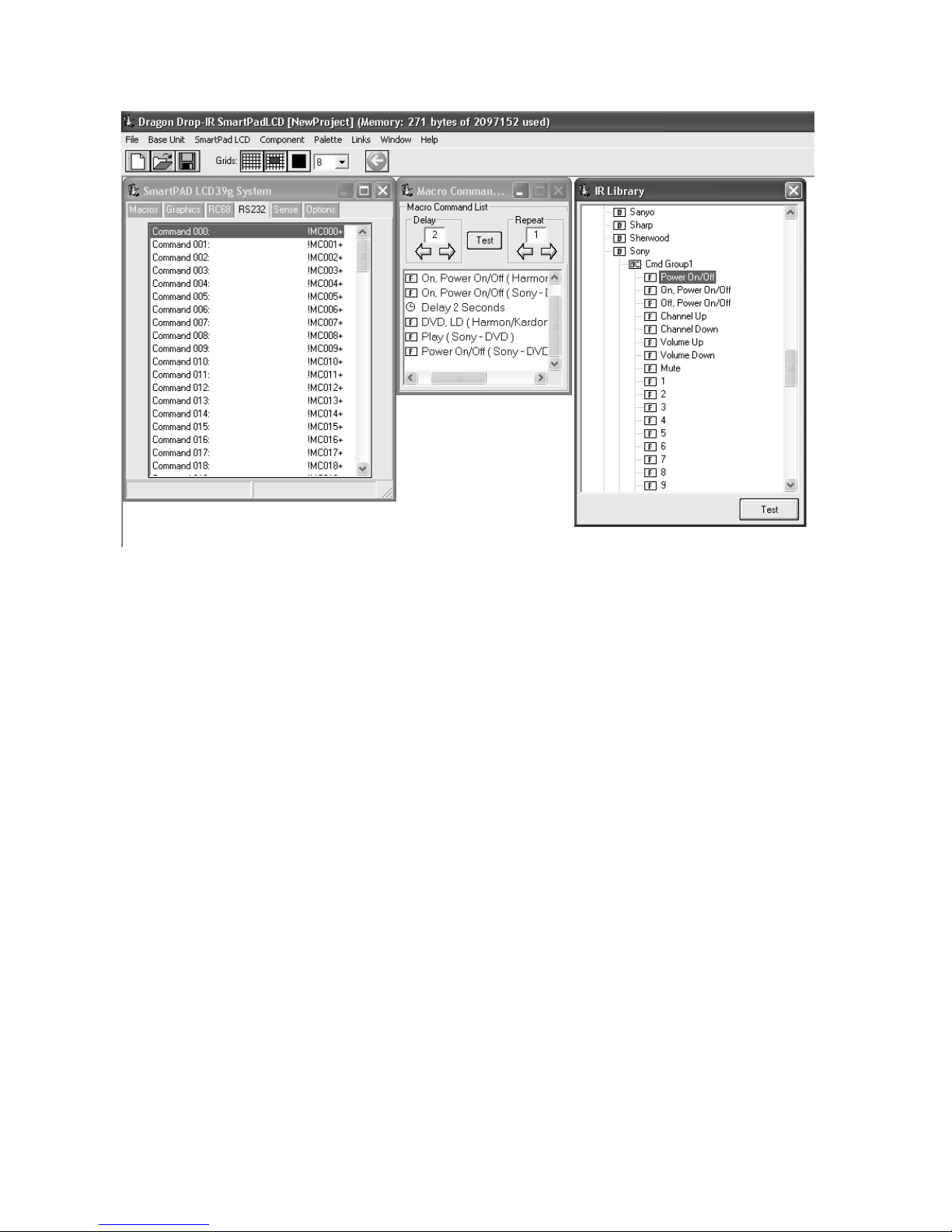
Page: 44 SmartPad LCD
Figure 28 –RS232 Input Translator
PROGRAMMING IR COMMANDS AND SEQUENCES
The RS232 Input Translator gets programmed in the same manner as programming macros under GTL buttons
or as outlined above in the RC68+ Sequencer programming. Codes from the IR Library (or stored Palette files)
are used to associate commands with any of the 128 available ASCII strings. This gives the ability to program
up to 128 different command strings to control external IR devices.
ELECTING IR PALETTES FROM THE IR CODE LIBRARY
S
1. Click on PALETTE in the DragSPLCD’s menu bar
2. Select IR LIBRARY from the drop-down menu
3. Click on the Component Type (i.e. VCR, TV etc.) and then the Manufacturer.
4. Select the proper Command Group (CMD).
5. Repeat for all components/commands being used in the macro
ELECTING IR PALETTES
S
1. From the Palette menu, click “SELECT IR COMMAND PALETTE” or press (F4) on the keyboard
A list of palettes file names appears to the right with Select Palette in the title bar.
2. Scroll the list (if necessary) and click on the filename of each palette you need for your system (i.e.
pioneercd.pal, rcadss.pal, etc).
3. As you click on each file name, the palettes will appear with the list of corresponding IR Commands.
SSOCIATING RS232 COMM ANDS WITH IR CONTROL CODES
A
1. Select an ASCII COMMAND string in the RS232 window numbered Command !MC000+ to Command
!MC127+. It will be highlighted in a blue background. (See Figure 27.)
2. In the appropriate palette, click on the command to be associated to the selected ASCII Command
string.
3. The code name (function/brand/component) for that ASCII string will appear in the Command List.
4. Repeat for all commands to be associated to this Command String. A maximum of 40 Commands may
be placed under each string.
5. Repeat steps 1 thru 4 for all desired ASCII Strings (128 in all)
© 2003 Xantech Corporation
Page 45

SmartPad LCD Page: 45
NOTE: It is recommended to write down the ASCII command string and a brief description of its
corresponding MACRO function. Each ASCII String will need to be entered into the controlling PC device as
it appears opposite the COMMAND Number. (i.e. to trigger ‘Command 000’ you will need to issue !000MC+
as the ASCII command string from the controlling PC). Use TABLE 2 in Appendix A to record the
descriptions of these commands.
ESTING COMM ANDS IN THE RS2322 INPUT TRANSLAT OR
T
Commands placed under ASCII Commands in the RS232 Input Translator window may be tested prior to
downloading to the SPLCD Controller. To test commands, the Dragon PC must be connected to the front panel
COM PORT or USB Port and emitters must be connected to the IR Bus of the SPLCD Display.
1. Select the ASCII Command String with the IR codes placed under it to test. (i.e. Command MC000+).
The command should now be hi-lighted.
2. Select the TEST button located in the middle of the Macro Command List window. Commands listed
under the Macro Command List for that selected ASCII Command should now be executed in order of
appearance out of the IR BUS output on the back of the SPLCD.
Note: RS232 commands may also be placed under the RS232 trigger macro to go back to the issuing RS232
device. For testing RS232 commands placed under this macro, the device needs to be connected to the DB9
serial output of the RS422232 converter as shown in Figure 10.
Note: Be sure the SPLCD is configured to Process RS232 Input commands. This setting can be found in the
RS232 Settings window under the OPTIONS TAB.
SENSE TRIGGER MACRO’s
The STATUS line located on the rear of the SPLCD (Figure 3-19c) may also be utilized to trigger a Macro (IR
and/or RS232). Two macro’s can be triggered when the incoming STATUS voltage is either High (5-30vDC) or
Low (0vDC). This is very useful for numerous applications such as a Doorbell trigger circuit to MUTE a
particular zone or to set a preferred lighting scene when a component is turned on or turn off all lights and A/V
equipment when an alarm system is activated.
PROGRAMMING OF SENSE INPUT
1. Select the SENSE tab in the SPLCD’s Systems window.
2. Select the Trigger Macro ON button in the Sense Setup window. The button should be outlined in blue.
3. Select the appropriate IR or RS232 command(s) to be associated with a Positive sense input (applied
voltage = 5 to 30VDC).
4. Select the Trigger Macro OFF button in the Sense Setup window. The OFF button should be outlined in
blue.
5. Select the appropriate IR or RS232 command(s) to be associated with the absence of a Sense Input
(i.e. 0VDC applied to the STATUS line).
INTELLIGENT POWER MANAGEMENT
The STATUS input can also be used for sensing the Power State of an external device or rack of equipment
and preventing unwanted Power Commands from being issued when not desired. If the device has a Status
Output (or a switched AC outlet with a DC Power Supply), whenever the device(s) are OFF (STATUS Line =
0VDC), a pre-programmed POWER ON Macro can be initiated when a Source GTL is pressed.
This feature will allow for a system Power Macro to be initiated whenever a Source GTL is pressed if the
STATUS line is low (STATUS = 0V). Whenever the STATUS Line is HIGH (STATUS = 5 to 30VDC), the macro
will not be played.
To Program Intelligent Power Management:
1. Select the Intelligent Power Management under the SENSE Tab in Dragon Drop-IR (SPLCD) software.
© 2003 Xantech Corporation
Page 46

Page: 46 SmartPad LCD
2. Open all palettes to be used in the POW ER ON macro and place the commands into the Macro
Command List Window.
Figure 29 – Sense Trigger Setup
Figure 29a – Intelligent Power Management
ASSIGNING BANK TRACK CODES TO SOURCE GTL’S
© 2003 Xantech Corporation
Page 47

SmartPad LCD Page: 47
By assigning discrete Bank Track Codes to each source button, the SPLCD can work in conjunction with
accompanying learning hand held remotes (similar to Xantech Model URC-2P/B) or other SPLCD panels in the
same zone. When a source is changed on the accompanying hand held remote (or another SPLCD panel), the
Source Pages will change in unison to remain in sync with the current Source selection.
To program a Bank Track Code:
1. Right-click on a source button and select PROPERTIES
2. Click on the Drop-Down menu for Bank Tracking
3. Select the desired Bank Track Code to be assigned to this Source Page
Note: Default Code Group for Bank Track codes is D8
Note: The URC-2P/B is pre programmed with Bank Track Codes 1 thru 8 and is directly compatible with the
SPLCD Bank Track Code system
Figure 30 – Assigning Bank Track Codes to Source GTL’s
FIRMWARE UPGRADES
The SmartPad LCD™ has been designed to be “Future Proof”. As product feature improvements are
developed, new System Firmware versions will be available. Periodically monitor www.Xantech.com
upgrades.
DOWNLOADING FIRMWARE FILES FROM THE WEB
1. Open the Dragon Drop-IR™ SPLCD software. Make sure you have an Internet connection as well as
having the SPLCD connected to your computer’s COM port (or USB port).
2. Select the Links menu item and then select Xantech Firmware Upgrade Page. This will connect to
the Xantech web site and load the Xantech Firmware Updates page in your browser. If you do not have
an active Internet connection, you will not be able to successfully complete this step or proceed.
© 2003 Xantech Corporation
for
Page 48

Page: 48 SmartPad LCD
3. Locate the most recent SPLCD firmware update file within the list - the one with the highest version
number (entries are sorted with the newest entries at the top of the list and the oldest at the bottom).
Click on the desired filename link to begin the download process.
4. A window will popup asking “Do you want to open the file or save it to your computer?” Select Save.
5. A Save As window will then open. Navigate to the FIRMWARE folder within the Daron Drop-IR
(SPLCD) folder (C:\Program Files\Xantech\Dragon Drop-IR (SPLCD)\Firmware). Click on Save.
6. Once the download is complete, click on Close to close the download window. You can also close your
browser.
FIRMWARE UPGRADE
Firmware upgrades can be conducted without having to re-transfer your project to the controller. It is a way of
keeping your unit up to date to take advantage of new features.
1. Start Dragon Drop-IR SPLCD software and connect your programming cable to the front programming
port (Serial or USB) of the SPLCD and open a project.
2. Select the SmartPad LCD Pulldown from the menu bar. Select Firmware Upgrade.
3. A popup window titled Select Firmware Upgrade File will open allowing you to select the firmware file
to be loaded into the SmartPad LCD Display. You should see the file that was just downloaded in step 6
above. Double-click on that filename to begin the update process.
After the firmware transfer is completed, select the Base unit menu item and then select Who am I? It should
now display the correct three-digit firmware version that you just loaded into the SPLCD unit. If this is true, the
new firmware has been successfully installed and is ready for use.
© 2003 Xantech Corporation
Page 49

SmartPad LCD Page: 49
Section 6: Options Settings
Under the OPTIONS Tab in the Dragon Drop-IR (SPLCD) Software, the user can change the default settings
for RC68 Code Group, Bank Track Code Group, STATUS Line and LED Operation, Backlight Control, Display
Orientation, and RS232 Port Settings.
Figure 31 – SPLCD Options Settings
RC68 CODE GROUP
The RC68+ Code Group setting refers to the group of IR codes that will be used to trigger RC68 Sequences as
discussed in Section 5. The number associated with this Code Group refers to the dial setting on the rear of the
RC68+ handheld programmer (See Figure 32 below). The Default Code Group the SPLCD will respond to is
C9. This setting only needs to be changed if numerous SmartPad LCD™ Panels or if there is an IR code group
conflict with some other device used in the same system.
© 2003 Xantech Corporation
Page 50

Page: 50 SmartPad LCD
Figure 32 – RC68+ Handheld Programmer Code Group
BANK TRACK CODE GROUP
When the SmartPad LCD™ is used in a system in conjunction with other controllers (i.e. Handheld remotes or
other SPLCD panels) in which the equipment can be controlled from multiple locations, the SPLCD panels have
the ability to track source selections simultaneously for in-sync operation with the current source selection.
i.e. If the user walks in a room and selects DVD on the SPLCD and then decides to select CD using a handheld
remote, the SPLCD will automatically switch to the CD source page. This works the same if multiple SPLCD’s
are used in a large room and a selection is made on one panel, the other panels will automatically switch to the
same source page currently selected.
The default Bank Track Code Group is D8.
STATUS LED SETTINGS
The Status LED (Figure 2-3) can be configured to track the STATUS line on the rear of the SPLCD (Figure 319C). If this is desired the TRACK LED SETTINGS dialog box should be set to YES. The Default setting is NO.
When the TRACK LED SETTING is set to YES, the STATUS LED will turn ON whenever a positive voltage (530VDC) is present at the STATUS Terminal on the rear of the SPLCD. Whenever this voltage is LOW (0VDC)
the LED will turn OFF.
This works in conjunction with the STATUS LINE role setting.
STATUS LINE ROLE SETTING
The Status Line on the rear of the SPLCD (Figure 3-19C) can be configured as either an INPUT to sense a
state of an external dev ice or as an OUTPUT to control some external device.
INPUT
When INPUT is selected under the STATUS L:INE ROLE SETTING and a 5 to 30VDC signal is present on the
STATUS terminal on the rear of the SPLCD, the following event/actions can be triggered:
© 2003 Xantech Corporation
Page 51
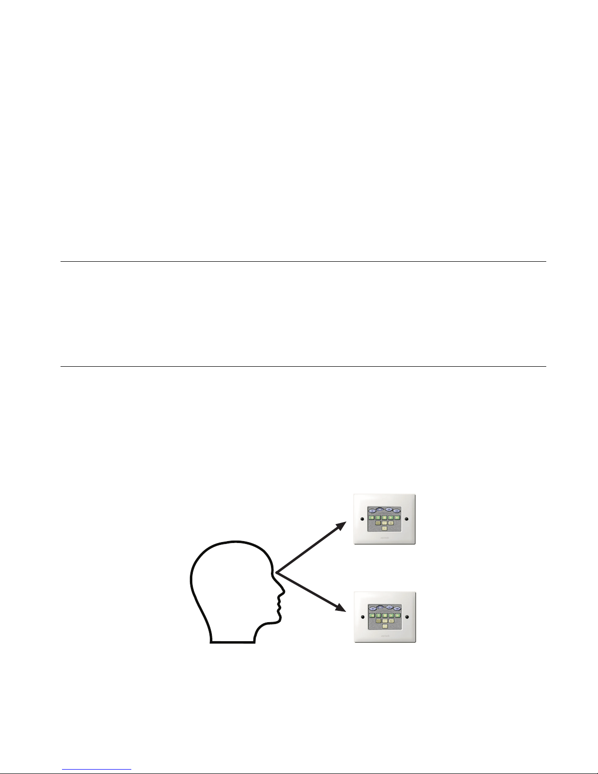
SmartPad LCD Page: 51
1. The STATUS LED on the front of the SPLCD Panel will be turned ON (Requires TRACK LED
SETTING to be set to YES).
2. Initiate a SENSE TRIGGER MACRO (if one is programmed under the ON button)
3. Utilize INTELLIGENT POWER MANAGEMENT (needs to be selected under the SENSE TAB)
Note: Items 1&2 or 1&3 may be programmed to occur simultaneously.
OUTPUT
When OUTPUT is selected, the STATUS Line can be programmed to transition to a 12VDC signal via an
Internal Command (STATUS LINE SET) placed under a GTL. This can be utilized to control and external
component via a 12V trigger whenever a GTL is pressed (i.e. Control a Screen Drop or Lift via a 12VDC Trigger
or turn on a remote amplifier).
Note: The STATUS output is rated at 15mA maximum.
BACKLIGHT CONTROL
Set the Backlight to stay ON for a specified amount of time after the last touch. The Backlight can be set to stay
ON from 1 to 30 seconds or to stay ON always.
Note: The IR receiver is disabled whenever the Backlight is ON. Therefore if ALWAYS ON is selected, the IR
Receiver will not be active.
DISPLAY ORIENTATION
The LCD Display needs to be configured for the proper viewing angle according to the position it will be
installed with regard to the user.
UP
Select this setting if the SPLCD will be installed at a height equal to or above the users eye level.
DOWN
Select this setting if the SPLCD will be installed at a height equal to or below the users eye level.
© 2003 Xantech Corporation
UP VIEW
DOWN VIEW
Figure 33 – Display Orientation
Page 52

Page: 52 SmartPad LCD
RS232 SETTINGS
To configure the settings of the SERIAL Port located in the rear of the SPLCD Controller –Figure 3-(21), click
on the RS232 SETTINGS button under the OPTIONS tab. This will display all configurable settings for the
RS232 control port. See Figure - 34 below for reference.
Figure 34 - RS232 Port Default Settings
BAUD RATE, DATA BITS, STOP BITS AM D PARITY SETTINGS
To change Baud Rate, Data Bits, Stop Bits or Parity settings, click on the corresponding to access the drop-down
menu and click on the desired setting. Default settings for all are shown above in Figure 34.
P
ROCESS RS232 INPUT
(Factory Default = “ENABLED”)
This setting should be enabled when the RS232 port will be used to receive data from a PC or other RS232
device (i.e. using the RS232 Input Translator). If the RS232 port will only be used to control an external device
from the Keypad (projector, thermostat controller, lighting system etc..), disable this setting to prevent the
SPLCD system from misinterpreting erroneous data.
© 2003 Xantech Corporation
Page 53

SmartPad LCD Page: 53
Section 7: Appendix
INTERFACING SPLCD with MRC44 & MRC88 (IR Control)
The SmartPad LCD™ allows direct integration with Xantech MRC Products via the CONTROL and
EXPANSION RJ45 Terminals on the rear of the panel (See Figure 3-13 & Figure 3-14). Connecting either of
these terminals to the Keypad Connection on the rear of the MRC44 or MRC88 will allow IR control of the MRC
unit and any components connected to the MRC Controller.
Note: External 16VDC Power wiring is still required via the Power Terminals. See Figure 3-19a & 19b)
PROGRAMMING SPLCD FOR USE WITH MRC44 (ZONE CONTROL)
1. Open a new Project (CTRL+N)
2. Choose the Base Unit (3.9G, 6.4G/V)
3. Select the Style
4. Place 4 Source GTL’s onto the SmartPad LCD Systems Window
5. Open the RC68+ Command Palette (Hit F5 on the Keyboard)
6. Select the OPTIONS TAB on the RC68+ Command Window
7. Under MODEL select MRC44 and verify the Code Group setting is the same as that of the MRC44
(Default Code Group = 48). Click on the Palette TAB to return to the RC68 Command window.
8. Click on a Source Button GTL in the SPLCD Systems Window that will select the component connected
to INPUT 1 on the MRC44 (i.e. CD as shown in Figure 35.
9. Select INPUT 1 on the RC68+ (00 Button) and verify the proper command description is shown in the
Macro Command List Window
10. Repeat for all Source Input GTL’s
11. Add a Source GTL and Label for OFF (if desired).
a. With the OFF GTL selected, press OFF (button 68) on the RC68+ Command Window and
verify the command as shown in the Macro Command List window.
12. Under each Source Page add Volume Buttons, MUTE or other commands as desired and place the
appropriate RC68+ command under the GTL button.
Figure 35 – Programming SPLCD for MRC44 IR Control
© 2003 Xantech Corporation
Page 54

Page: 54 SmartPad LCD
PROGRAMMING SPLCD FOR USE WITH MRC88 (ZONE CONTROL)
1. Open a new Project (CTRL+N)
2. Choose the Base Unit (3.9G, 6.4G/V)
3. Select the Style
4. Place 8 Source GTL’s (or as many as needed for that Zone) onto the SmartPad LCD Systems Window
5. Open the RC68+ Command Palette (Hit F5 on the Keyboard)
6. Select the OPTIONS TAB on the RC68+ Command Window
7. Under MODEL select MRC88 and verify the Code Group setting is the same as that of the Zone on the
MRC88 (Default Code Group = A8). Click on the Palette TAB to return to the RC68 Command window.
8. Click on a Source Button GTL in the SPLCD Systems Window that will select the component connected
to INPUT 1 on the MRC88 (i.e. CD as shown in Figure 36.
9. Select INPUT 1 on the RC68+ (00 Button) and verify the proper command description is shown in the
Macro Command List Window
10. Repeat for all Source Input GTL’s
11. Add a Source GTL and Label for OFF (if desired).
a. With the OFF GTL selected, press OFF (button 68) on the RC68+ Command Window and
verify the command as shown in the Macro Command List window.
12. Under each Source Page add Volume Buttons, MUTE or other commands as desired and place the
appropriate RC68+ command under the GTL button.
Figure 36 – Programming SPLCD for MRC88 IR Control
Note: To create Toggle POWER or MUTE commands, program the MRC88 (or 44) for Toggle POWER or
MUTE Internal Amplifier Commands under the RC68+ Trigger Sequencer within the DragMRC software
(Refer to the MRC88 Manual; Section 5: RC68+ IR Code Triggered Sequencer) See Figure 37a below.
Place the same RC68+ IR commands under the designated GTL button in the SPLCD Software. See
Figure 37b below.
© 2003 Xantech Corporation
Page 55

SmartPad LCD Page: 55
Figure 37a - MRC88 Toggle Power Programming
Figure 37b - SPLCD-MRC88 Zone Toggle Power Programming
© 2003 Xantech Corporation
Page 56

Page: 56 SmartPad LCD
SmartPad LCD 6.4” VIDEO: VIDEO CONNECTION & PROGRAMMING
SmartPad LCD™ 64V:
Software Note:
Checking Software
Version:
The SmartPad LCD 64V includes the same features as the 64G
(Graphics version) now with PiP and Full Screen video display. This
version also allows for “Trasparent Button” Overlays presenting a
clear & seamless integration for video menu device control.
This panel and its features must be accompanied with Dragon Drop-
IR (SPLCD) Version 1.2.0 or above and Firmware Version 1.29 or
above.
To check the software version, open Dragon Drop-IR (SPLCD) and
click on the HELP Menu and select ABOUT. The Software version
shall be noted at the top of the pop-up window. If it is not noted or
the version does not read 1.2.0 or higher, please see
www.xantech.com
and download the latest version of Dragon Drop-
IR SPLCD.
Checking
FirmwareVersion:
Video Connections:
To check the SPLCD64V for proper firmware version, connect the
panel to the PC running Dragon Drop-IR (SPLCD) and click on the
Base Unit Menu and select WHO AM I from the drop-down menu.
Connect the composite video signal to the SPLCD 64V via the BNC
connection labeled VIDEO IN on the rear of the panel.
A buffered composite video signal can also be run OUT of the panel
to a main Video Monitor in the Zone if desired. To do this, connect a
coax cable to the BNC connection labeled VIDEO OUT on the rear of
the panel.
VIDEO BRACKET SUB-ASSEMBLY
T
U
O
O
E
ID
V
IN
O
E
ID
V
MOUNTED ON LEFT SIDE (1ST OPTION)
© 2003 Xantech Corporation
Page 57

SmartPad LCD Page: 57
Picture-In-Picture
Mode (PiP):
A PiP window can be opened on any GTL (Graphical Touch Link) Page
desired. To enable a PiP:
1. Right-Click on a blank space and select Enable PiP from the
pop-up menu.
2. Click-&-Hold the PiP and Drag to the desired location on the
GTL page.
3. To resize the PiP, right-click on the PiP and select the desired
screen size.
Enabling Full-Screen
Video Mode:
Once the project is downloaded to the SPLCD 64V base unit, the PiP
can be touched to enable Full Screen video mode.
To Return to PiP Mode:
Simply touch the middle of the video screen to return back to PiP mode.
TRANSPARENT BUTTON OVERLAY: FEATURES & PROGRAMMING
Transparent Button GTL
Overlay Feature:
This feature allows for transparent ‘invisible’ button GTL to be placed on
the video screen during Full-Screen Video mode or any screen desired.
This is extremely useful for Music Server Control with feedback display
on units that output a Video Menu (theme) with buttons imbedded in the
video. This is also useful for hiding Volume UP & DOWN or Channel UP
& DOWN functionality to be available even when in Full-Screen Video
mode.
For Full Screen Transparent Button Overlay Functionality:
1. Right-click on the PiP screen and select NAVIGATE from the
pop-up menu.
Note: A Full Screen page will appear with a transparent button
object displayed in the middle. This object is the Return to PiP
button and cannot be removed. This button can be resized and
moved to any desired location.
2. To add a Transparent Button GTL simply right-click anywhere on
the blank area of the screen and select Insert Object from the
pop-up menu.
3. Select Insert Transparent Button from the pop-up menu. A
Transparent Button will appear outlined on the screen.
© 2003 Xantech Corporation
Page 58

Page: 58 SmartPad LCD
4. Click-and-drag the button to the desired location (must be in
GRAPHICS Mode)
5. The button can be re-sized easily by clicking on one of the blue
squares outlining the button and dragging the square to the
desired size.
Transparent Button GTL
Music Server
Integration:
Volume UP
Exit
Volume
Chan UP
Chan Down
6. After all desired buttons are placed and sized appropriately on
the PiP Video screen, you can now assign IR and/or RS232
Macro’s to these buttons in the same manner as a standard
GTL. (I.e. Assign top right and bottom right buttons as Channel
UP/Down or Volume UP/DOWN.)
To interface to a Music Server Video Menu Screen (or any other
products Video Menu Screen), follow the steps below. If the product
interfacing to has a BMP (bitmap) file for reference, you can display this
image in the software and drag and drop transparent buttons over it for
seamless control of the device.:
1. Right-click on the PiP screen and select NAVIGATE from the
pop-up menu.
Note: A Full Screen page will appear with a transparent button
object displayed in the middle. This object is the Return to PiP
button and cannot be removed. This button can be resized and
moved to any desired location.
2. Right-Click anywhere on the blank area of the screen and select
Add Video Image Template from the pop-up menu.
© 2003 Xantech Corporation
Page 59

SmartPad LCD Page: 59
3. Select the BMP image that represents the video menu to display.
4. Follow steps 3 thru 6 as displayed above to add Transparent
GTL’s to the template PiP and assign functionality to the GTL’s.
Other Uses for
Transparent GTL’s:
The transparent GTL feature is available for use on ALL versions of the
SmartPad LCD™ Controllers (SPLCD39G, 57G, 64G, and 64V).
Transparent GTL’s can be placed anywhere over an object such as a
picture used as a backdrop, Volume Bars etc…
See the example below illustrating how Transparent GTL buttons can be
placed over areas of a custom background for realistic visual
functionality:
Note: Please see section on IMPORTING BACKGROUNDS for
instructions. After the desired background is placed on the SmartPad
LCD™ Systems window, place Source buttons as you would normally
and then follow the instructions below for adding Transparent Button
GTL’s:
© 2003 Xantech Corporation
Page 60

Page: 60 SmartPad LCD
1. To add a Transparent Button GTL simply right-click anywhere on
the blank area of the screen and select Insert Object from the
pop-up menu.
2. Select Insert Transparent Button from the pop-up menu. A
Transparent Button will appear outlined on the screen.
3. Click-and-drag the button to the desired location.
4. The button can be re-sized easily by clicking on one of the blue
squares outlining the button and dragging the square to the
desired size.
MRC88 EMULATION MODE: FEATURE DESCRIPTION & PROGRAMMING
MRC88/SmartPad™
LCD Emulation Mode:
Connecting the SPLCD
to the MRC88
Controller:
Configuring Dragon
Drop SPLCD for MRC88
Emulation Mode:
The full line of SmartPad™ LCD Controllers can be seamlessly integrated into
a new or existing MRC88 System over the standard CAT5 cable. This allows
the SmartPad LCD™ Controller to access any macro programmed in the
MRC88 Controller without the use of IR commands. All Macro Programming
resides in the MRC88 allowing for ease of initial programming and any
upgrades that should occur.
1. Connect one end of the CAT5 to the Keypad port on the rear of the
MRC88 Controller and the other end to the Controller port on the rear
of the SPLCD Panel.
2. 16Vdc Power must still be run directly to the +16VDC and GND
Terminals on the rear of the SPLCD panel.
Note: The SPLCD cannot be powered directly from the MRC88 Controller.
3. If using multiple keypads in a single Zone, the last keypad in line must
have the Zone Termination Jumper installed.
Note: The SPLCD comes with the Zone Termination Jumper installed by
default.
1. Program the MRC88 as you would for a standard MRC88 Keypad
using both the Tier1 and Tier2 of the buttons for added functionality.
2. Create the graphic layout for an SPLCD project in Dragon as you would
normally.
3. After all of the GTL’s are layed out as in a standard SPLCD project,
click on the TAB labeled MRC88 in the SPLCD Systems Window.
4. Check the box labeled Emulate MRC88 Keypad
5. If you are using Multiple Keypads in a single zone, set each keypad to
a unique Keypad Address. Up to four keypads can be used together
in a single zone. Note: If using standard MRC88 Keypads in
conjunction with the SPLCD in the Zone, you must set the MRC88KP
Address Jumper to the specific address.
6. Under MRC88 Source Names enter the names as they appear in the
MRC88 Software. Note: This is necessary for proper Source Name
display when using the MRC88 STATUS function.
© 2003 Xantech Corporation
Page 61

SmartPad LCD Page: 61
Name Each Source
as it appears in the
DragMRC Pr oject.
Programming SPLCD for
MRC88 Functionality:
Once Dragon Drop SPLCD is configured for MRC88 Keypad Emulation, you
can now point each GTL on the SmartPad LCD™ to a specific macro within the
MRC88 Controller.
1. Click on the MACROs Tab to lock in the current GTL button layout.
2. Select a Source Button in the SPLCD Systems Window.
3. Click on the PALETTES menu and select Internal Commands from
the drop-down menu.
4. Click on Backlight Set in the Internal Command Window and select
MRC88 Button Id from the drop-down menu.
These are pointers to buttons within the MRC88 Controller. Whatever Macro is
programmed within the MRC88 under these buttons, the SPLCD can now
execute these Macro’s.
5. Scroll through the list and associate SPLCD buttons to Macros
programmed under specific buttons within the MRC88 Controller. I.e.
Click on a Source Button and then select Src 1 from the MRC88 Button
Id list as in the example below.
6. Repeat above for all of the Source Buttons.
7. Repeat the same procedure for PLAY STOP PAUSE etc……
8. You can even assign SPLCD GTL Buttons to an MRC88 Tier 2 Macro.
© 2003 Xantech Corporation
For example: Assign the 5 Motion control buttons to as Tier 1 PLAY
STOP PAUSE etc… In your MRC88 Project program Tier 2 of the
PLAY STOP PAUSE etc.. buttons as MENU Navigation buttons and
Page 62

Page: 62 SmartPad LCD
now select a SPLCD Button for ENTER and assign it the PLAY TIER 2
Button Id.
9. Continue this for all buttons on the SPLCD (i.e. MRC88 Volume Up,
Down OFF MUTE etc….) that you want to control the MRC88.
10. If more button control is needed from the SPLCD you can still program
standard buttons to pass IR through the CAT5 and MRC88 Controller
as you would in a standard project.
For Macro functionality, use RC68 IR Trigger codes within the MRC88
Software. Therefore the SPLCD only needs to send a single IR command to
trigger a long macro within the MRC88. This keeps all of the Macro
programming within the MRC88.
Placing MRC88 Objects
on the SPLCD:
You can also place MRC88 graphic objects on the page. Objects that can be
displayed are as follows:
• STATUS Display: Displays Zone Status, Source Icons, and Zone
Linking information from the MRC88
• INFORMATION Display: Xantech XDT Tuner Feedback display,
MUTE and ZONE OFF status, Priority Lockout, etc.
• Horizontal Bars: Horizontal bar for Volume display or EQ/ Balance
level display
• Vertical Bars: Vertical Bar for Volume display or EQ/Balance display.
To display one or more of these objects,
1. Right-click on a blank area of the background.
2. Select Insert MRC88 Object from the drop-down menu.
3. Choose from Horizontal or Vertical Volume, EQ/Balance bars,
Informational Display, or Status Display.
Note: Once placed on the SPLCD Systems window, these objects can be
moved to any desired location and the border colors can be modified to fit the
desired style.
Horizontal and Vertical Bars can be resized for length and width. STATUS and
INFORMATION displays cannot be resized.
MRC88 OBJECT PROGRAMMING: ADDING VOLUME BAR, STATUS BAR ETC…
Tansparent GTL’s and
MRC88 Emulation:
Combining these two features allows for unique programming possibilities.
Below is an example for creating Interactiv e Volume Bars so the user can press
different areas of the Volume bar and have the Zone Volume Level jump
immediately to that level. In this particular example we will separate the Volume
Bar into three sections, Low Level, Mid Level and High Volume Level.
This will require programming in both DragMRC and Dragon Drop-IR SPLCD.
MRC88 Volume Level Programming:
(Refer to the MRC88 Manual; Section 5: RC68+ IR Code Triggered Sequencer
for further explanation of the following):
© 2003 Xantech Corporation
Page 63

SmartPad LCD Page: 63
1. Within DragMRC Software, select the Zone Keypad the SPLCD will be
connected to.
2. Click on RC68 on the lower right of the MRC88 Systems Window
3. Click on Palette and select MRC Amplifier Command Generator.
4. Click on the Drop-Down arrow and select Zone Volume Command.
5. Select the Zone # (in this case Zone #1)
6. Select the [80] button on the Virtual RC68 (or any other free RC68
Trigger button).
7. Select a discrete Volume Level for the LOW setting (i.e. 20) and select
APPLY.
8. Repeat for two other RC68 trigger buttons for a Mid Volume level and a
Hi Volume Level (i.e. place discrete volume lev el 40 command under
button [48] and discrete Volume level 50 under button [10] on the
virtual RC68.
Configuring SPLCD in Dragon Drop-IR SPLCD:
© 2003 Xantech Corporation
Page 64

Page: 64 SmartPad LCD
RC68 Trigger
Command
Transparent GTL
plac ed over MRC88
Volume Bar
Placing the Volume Bar:
1. Right-click on a blank area of the background and select Insert MRC88
Object from the drop-down menu.
2. Choose from Horizontal or Vertical Volume bar.
3. Place and resize to desired position.
Creating Transparent GTL’s over Volume Bar:
1. Right-Click on a blank area of the background and select Insert Object
– Insert Transparent Button from the drop-down menu.
2. Resize the box to cover 1/3 of the volume bar and place over the
bottom 1/3 of the Volume Bar.
3. Place 2 more Transparent GTL boxes over the middle and upper 1/3 of
the section of the Volume Bar
Assigning the Proper RC68 IR Codes to the Transparent GTL’s
1. Click on Palettes and select RC68 Command Palette from the menu.
2. Click on the OPTIONS Tab on the Virtual RC68 Palette and choose
MRC88 from the Xantech Model drop-down menu.
3. Click on the PALETTE Tab on the Virtual RC68
4. On the SPLCD Systems window, select the Transparent GTL placed
on the lower 1/3 of the Volume Bar.
5. Select the [80] button from the Virtual RC68 Palette (under the
Command List Window you should see the command ‘A(XantechMRC88)A,A8’ )
6. Repeat steps 4 and 5 for the Middle and Hi level Transparent GTL with
the RC68 [48] and [10] commands as shown above.
IMPORTING CUSTOM BACKGROUNDS:
Importing Pictures as
Custom Backgrounds:
This is easiest performed on the SPLCD64G and SPLCD64V units due to
increased screen resolution (640x480).
Use the following guide lines when importing user-defined Bitmap images,:
© 2003 Xantech Corporation
Page 65

SmartPad LCD Page: 65
1. The image must be sized to 640x480 pixel resolution.
2. The image must be saved as a 16Bit 64k color Bitmap Image.
3. Place the image into the desired Style Background folder
Note: Background Style Directories are located at
C:\Program Files\Xantech\Dragon Drop-IR(SPLCD)\Icons\SPLCD folder as
shown below.
4. Re-start Dragon Drop-IR (SPLCD) software and select the Style
imported to and click on the Backgrounds folder and you should see
the imported background.
© 2003 Xantech Corporation
Page 66

Page: 66 SmartPad LCD
XANTECH CORPORATIOIN
12950 Bradley Avenue, Sylmar CA 91342-3829
phone 818.362.0353 · fax 818.362.9506
www.xantech.com
Part No. 08901480 Rev B 10-28-04
© 2003 Xantech Corporation
 Loading...