

Page 1
INSTALLATION INSTRUCTIONS
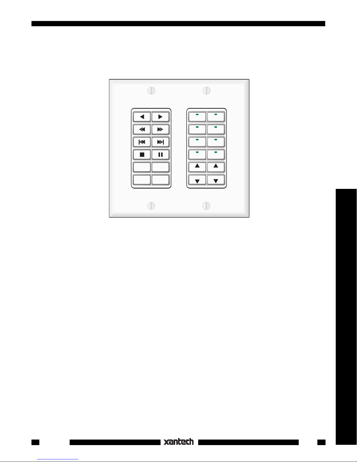
SMARTPAD
™
3
PROGRAMMABLE KEYPAD SYSTEM
CD
CATV
TAPE
LD
CAM
TUNER
VOL
VOL
AM/FM
OFF
GLOBAL
MUTE
VCR
SAT
TNR
TNR
Controllers
INTRODUCTION
The SmartPad
is the next generation of the SmartPad2, the world's first wall mounted, IR learning,
3
programmable modular keypad system. It incorporates many unique features to accommodate the growing
needs of the fast moving custom installation marketplace.
UNIQUE FEATURES
• Eight different Key Modules are provided which dock into three different Base Modules. Over 50
keypad combinations are possible!
• One, two and three gang wall mounting options are available.
• Buttons are replaceable and interchangeable within the key module.
• A selection of buttons with commonly used markings are included with each key module. Many
specialized versions are also separately available from Xantech.
• Pre-labeled buttons do not require any tedious insertion of small icon key "caps".
• Up to 8 memory banks can be selected by source buttons with LED indicators.
• Two tiers of memory per button. 2nd tier is accessed by "Push and Hold". Applies to both source select
and control function keys.
• Sequence commands, including 1 to 30 second delays, can be programmed into any button (including
the 2nd tier) without using up button spaces anywhere else on the keypad.
• Status Input permits source buttons to light up with +5 to +30V representing a system power ON condition
as well as the selected source.
• Intelligent Power Management. Allows power commands to be sent only if the system or zone is Off,
thus preventing unintended shutdown when switching sources.
• IR Commands are "learned" directly from hand held remotes or by using Xantech's exclusive
Dragon Drop-IR™ software.
Smart Pad
3
1
Page 2
• Network Cloning permits simultaneous transfer of programmed contents from one keypad to as many
as 16 keypads wired on the same IR bus (single zone network).
Cloning can also be done from one keypad to another, or from a "virtual" keypad created with Dragon
Drop-IR™, via the COM Port.
®
• Dragon Drop-IR™ (optional), a Windows
based program, permits rapid configuring, learning, duplica-
tion and filing of SmartPad3 programming.
• Speaker Relay permits local muting of speakers for single zone systems.
• Code Group and Bank Tracking Programming permit specialized configurations.
2
PROM stores memorized contents. No backup batteries needed!
• E
• Write/Protect switch safeguards memory contents.
• Memory. LM110; 8 kbytes. PM110; 32 kbytes.
• Standard 4 terminal output allows use on same IR bus as all Xantech IR Receivers and controllers.
MODULE DESCRIPTIONS
Perhaps the easiest way to become familiar with the SmartPad
that make up the system. The modules are divided into two basic groups: the
Base
the docking
modules. The Key modules plug into the Base modules.
is to gain an understanding of the modules
3
Key
(or button) modules, and
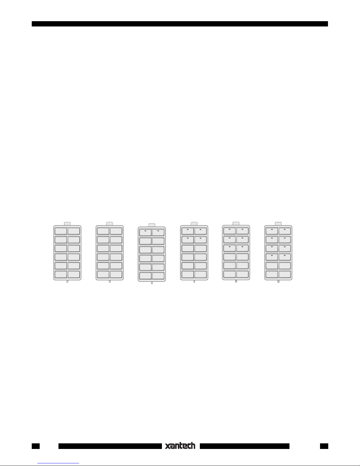
The Key Modules
There are ten single-gang key module assemblies currently available. The first six shown have 12 buttons.
The last four have 11 buttons and include a cursor key cluster. The module shells and buttons are available
in white, ivory and black. An illustration and description of each follow:
KM1F
KM1N
KM2
KM4 KM6
KM8
The KM1F module can be used as a single-gang single-bank keypad or, with other source selection or
function modules, for 2 or 3-gang configurations. A selection of function buttons are included for function
control commands.
The KM1N is similar to the KM1F except it is intended for direct numeric entry of channels on DSS receivers,
disk/track selection on CD changers, etc. It can be used with other source or function modules for 2 or 3gang configurations. Numeric and some function buttons are included.
The KM2 includes 2 source (bank) keys and 10 function control keys. It can be used as a single-gang two-
source (bank) keypad or, with other function modules, in 2 or 3-gang configurations. A selection of source
and function buttons are included.
The KM4 and KM6 are similar to the KM2, except they have 4 source, 8 function and 6 source, 6 function
keys respectively. Again, they can be used in 2 or 3-gang configurations. A selection of source and
function buttons are included.
The KM8 includes 8 source and 4 function keys. Again, it can be used as a single-gang 8-source (bank)
keypad, or, with other function modules, for 2 or 3-gang configurations. A selection of source and function
buttons are included.
2
Smart Pad
3
Page 3
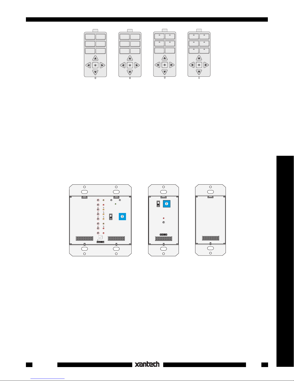
CM1N
CM1F
CM4
CM6
The CM1N is similar to the CM1F except that it is set up for use with 6 numeric control buttons as well as
the 5 cursor keys. Numeric and cursor buttons are included.
The CM1F module includes 6 function control keys plus a cursor button cluster with Up, Down, Left, Right,
and Enter keys. The cursor keys can be used with sources that have menu driven on-screen displays.
Cursor keys and a selection of function buttons are included.
The CM4 is similar to the CM1F except that it is set up for use with 4 source (bank) and 2 function keys as
well as the 5 cursor keys. Cursor keys and a selection of source and function buttons are included.
The CM6 is similar to the CM1F except that it is set up for use with 6 source (bank) keys as well as the 5
cursor keys. Cursor keys and a selection of source buttons are included.
The Base Modules
There are three base modules in the SmartPad
system into which the Key Modules are docked. They
3
contain the electronics for programming & memory (except the EM110) and include flanges for J-box
mounting. An illustration and description of each follow:
PGM
CLR MEM RESTORE
CNCL
FULL
NETWORK
SEQ
DELAY
WRITE
0
1
F
2
E
3
D
4
C
EDIT
PROTECT
STEP
TRNS
DEL
XFER
ERR
IR
C
O
M
B
A
NETWORK
ADDRESS
5
6
7
9
8
PM110 LM110
WRITE
PROTECT
COM PORT
F
E
D
C
B
A
NETWORK
ADDRESS
NETWORK
RESTORE
0
1
2
3
4
5
6
7
9
8
EM110
The PM110 dual gang Programmable Module is the base module for programming all of the commands
and functions required for each installation. All programming, including sequences (macros), is done with
the PM110 (unless done with Dragon Drop-IR™).
Controllers
The LM110 Learning Module is intended for single gang applications and must receive its programming
from a PM110 or Dragon Drop IR™ system. Programs are transferred from the PM110 or Dragon Drop IR
to the LM110 with a 2-step transfer command.
The EM110 is a single gang Expansion Module. It has no memory and serves only to expand the number
of key functions for the PM110 in 3-gang configurations.
Smart Pad
3
3
Page 4
BASIC CONFIGURATIONS & PROGRAMMING
Now that we have a conceptual understanding of the basic SmartPad
system, let's dive right in and create
3
three basic module and button configurations and apply the applicable programming.
A Two Gang Configuration
Suppose a client wants to control an AM/FM stereo system from a remote room with one 2-gang keypad
and that he has the following equipment and system requirements:
1. An AM/FM receiver and 4 sources: TUNER (AM/FM), two CD changers and a cassette TAPE deck.
2. When a source button is pressed, the Smart Pad must turn on the AM/FM receiver and the associated
source.
3. The keypad must have the following control function commands for each source:
TUNER: Tuner Up/Down (scroll of preset stations), AM/FM (select).
CD 1 and CD 2: Play, Scan Forward/Reverse, Track Forward/Reverse, Disk+, Disk– (select), Pause,
Stop.
TAPE: Play Forward, Play Reverse, Fast Forward, Rewind, Pause, Stop.
4. Speakers in the remote room must be mutable by using the relay in the SmartPad
This is the basic client specification for this application of the SmartPad
3.
3.
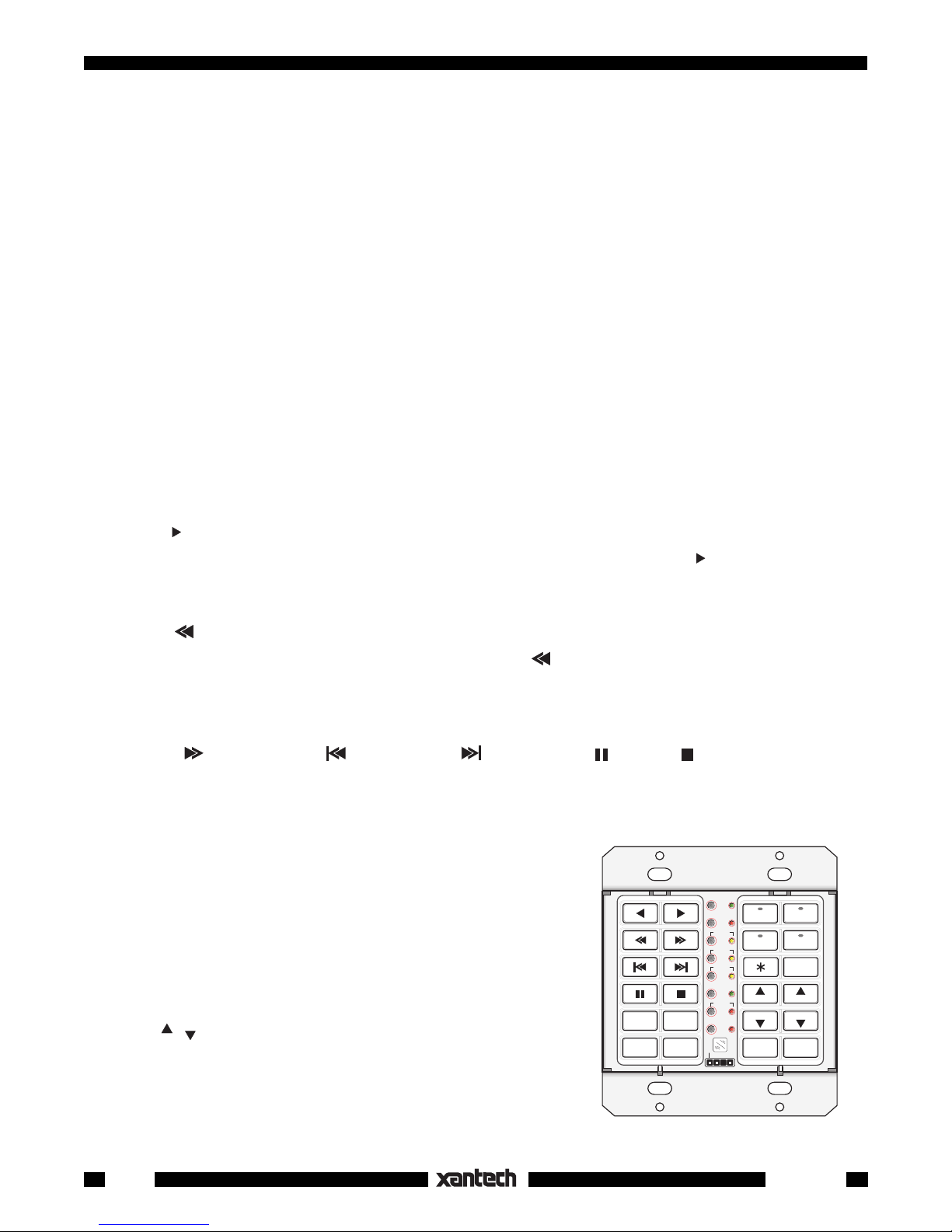
The next step is to determine what SmartPad3 modules and keypad buttons are required to perform this
job, as follows:
1. Since there are 4 sources, 4 banks will be required. We will need the KM4 for the first Key Module.
2. Since there are a good number of control functions to perform, we will need the KM1F for the second
Key Module.
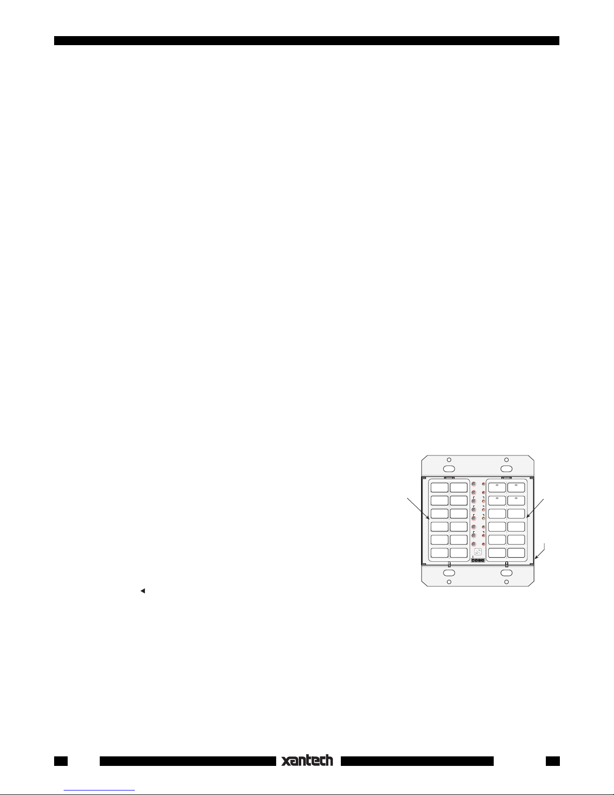
3. Now, since this is a 2-gang configuration, we need a PM110 Base Module into which we plug the KM1F
and the KM4. Fig. 1 shows the basic configuration.
4. The next step is to determine exactly what buttons are required
to carry out the control functions needed.
PGM
CLR MEM RESTORE
CNCL
5. We begin this process by assigning the Source buttons first;
CD1, TUNER, CD2 and TAPE. See Fig. 2.
6. Next, we assign the function control buttons based on the list of
functions given on page 7.
NOTE: Most of the buttons for steps 5 and 6 are available in the
KM1F
FULL
NETWORK
SEQ
DELAY
WRITE
EDIT
PROTECT
STEP
TRNS
DEL
XFER
ERR
IR
C
O
M
E
D
C
B
NETWORK
ADDRESS
KM4
1
0
F
2
3
4
5
6
A
7
9
8
PM110
SOURCE bag of buttons supplied with the KM4 and in the FUNCTION
bag of buttons supplied with the KM1F. Buttons CD1, OFF, RANDOM, A/B, * and
separately from Xantech. They are listed in the dealer price list (along
with all buttons currently available for the SmartPad
(reverse play) are not supplied but are available
system). They should be ordered at the same time as
3
Fig. 1 Two Gang Configuration
the other keypad parts.
7. Now that all the buttons have been assigned (as shown in Fig. 2), it is necessary to insert them into
the KM1F and the KM4 module shells. Then insert the completed key modules into the PM110. See
page 18 for Button and Module Assembly instructions.
NOTE: In this example, the button and module positions are placed in what is considered an ergonomically
pleasing arrangement. You may, however, place the buttons in any arrangement you wish, to best fit taste
and application.
4
Smart Pad
3
Page 5
The only exception to this is the 4 source buttons. They need to be
kept in the 4 upper locations of the KM4 in order for the source
indicators and bank selections to operate.
You may also reverse the position of the KM1F and the KM4
modules; the basic operation of the keypad will be identical.
8. The keypad is now ready to be wired into the total system. See
Fig. 3. Power may then be applied and we can proceed with the
Programming of each key.
Programming a Two Gang Configuration
RANDOM
DISC–DISC
PGM
CLR MEM RESTORE
CNCL
FULL
SEQ
DELAY
EDIT
STEP
TRNS
DEL
A/B
XFER
ERR
IR
C
O
M
+
CD 1
CD 2
WRITE
PROTECT
TNR
TNR
MUTE
NETWORK
TUNER
TAPE
F
E
D
C
AM/FM
B
A
NETWORK
ADDRESS
VOL
VOL
OFF
1
0
2
3
4
5
6
7
9
8
Before proceeding with this section, it is recommended that you read
"PROGRAMMING THE SMARTPAD
™ ", page 20, where full pro-
3
gramming details are given. The following is a brief procedure,
Fig. 2 Two Gang Button Assignments
specific to this installation example. It assumes you already have
some familiarity with the programming procedures. NOTE: STATUS
and AC power management are accomplished using sequenced commands and the Switched AC Outlet
on the AM/FM receiver. Refer to Fig. 3.
We'll begin by "teaching" commands to the 4 source (bank) buttons:
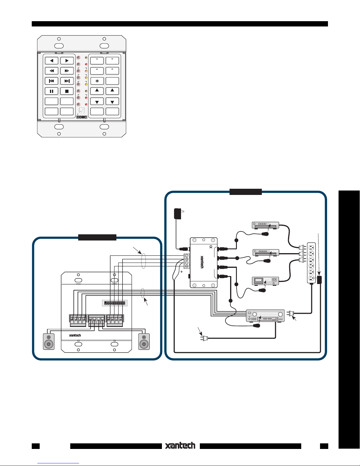
Fig. 3 Typical Connection Diagram, Based on Client Specification
REMOTE ROOM
4-Conductor
IR Signal Cable
+12V
GND
STATUS
OUT
PM110
SmartPad
(rear view)
Left
Speaker
PM110
SMART PAD
3
PROGRAMMABLE MODULE
AMPLIFIER
L+ L– R– R+
SPEAKER
OUTPUT
INPUT
L+ L– R– R+
SYLMAR, CA MADE IN U.S.A.
®
TO EM110
4-Conductor
+12V
IR OUT
STATUS
Speaker Cable
GND
Right
Speaker
781RG
Power Supply
To 120 V AC
(Unswitched)
–
Power Cord for
AM/FM Receiver.
Plug into an
Unswitched
AC Outlet
789-44
Connecting Block
12VDC
CONNECTING BLOCK
+12 VDC
789-44
GND
STATUS
IR IN
®
RCVR
IR
EMITTERS
MAIN ROOM
Cassette Deck
AM/FM Receiver
282M
Mouse Emitter
CD Changer
283M
Blink IR™
DVD
283M
282M
Blink IR™
Mouse Emitter
Switched
on AM/FM Receiver
786-00
Power Supply
(12V)
AC
Power
Strip
Plug into
AC Outlet
(see text)
Controllers
1. Press SEQ. The SEQ LED will flash.
2. Press CD1. CD1 LED will come on and the SEQ LED will come on steady.
NOTE: Turn the AM/FM receiver ON so that +12V is applied to the STATUS line. This ensures that
the source button LED's will light.
3. Point the AM/FM receiver remote at the IR window and press it's POWER key.
4. When the code is learned, the SEQ LED will flash and then go steady when you release the POWER
key on the remote.
Smart Pad
3
5
Page 6
5. Press DELAY. DELAY LED will flash. Press DELAY once again to enter a 1 second delay. (The
1 second delay allows some time for the AM/FM receiver to power up to be sure it will execute the CD
source command).
6. Press CNCL to return to SEQ mode.
7. Point the AM/FM receiver remote at IR window and press it's CD1 (source) button.
8. When the CD1 code is learned, the SEQ LED will flash then go steady when you release the CD1 key
on the remote.
twice
9. Press CNCL
to leave the sequence mode.
You can now test the learned commands. But first, be sure the AM/FM receiver's Power is turned OFF and
the emitters are placed on each of the components as shown in Fig. 3. Now press the CD1 button. The AM/
FM receiver should turn ON and it's source selector should switch to the CD1 position.
Using the same procedure, program the remaining source buttons. Just be sure to press the correct source
button in steps 2 & 7 above. As you complete each source (bank) button, test it before going on. Repeat
the procedure, as necessary, until correct operation is obtained.
When the source buttons are complete, proceed to program each of the 20 function buttons as follows:
1. First, press CD1 to select the CD1 bank. The functions that apply to this source (bank) will now be
"taught" (programmed) into the applicable function buttons.
2. Press PGM. The PGM LED will flash.
3. Press
4. Point the CD1 (CD player) handheld remote at the IR window and press it's
(play) button. The PGM LED will come on steady.
(play) button.
5. When the code is learned, the PGM LED will flash again, indicating it is ready to learn a command at
another button.
6. Press (reverse scan) button. The PGM LED will come on steady.
7. Point the CD1 remote at the IR window and press it's
(reverse scan) button.
8. When the code is learned, the PGM LED will flash again, indicating it is ready to learn a command at
another button.
9. Using this same procedure, program all the remaining commands that are applicable to the CD1 as
follows:
DISC
and
( forward scan), (reverse skip), (forward skip), (pause), (stop), RANDOM,
).
+
10. When finished, press CNCL to leave the PGM mode.
At this point, check all commands to see that they operate correctly. Reprogram as necessary.
11. Next, press CD2 to select the CD2 bank. Program the 2nd CD
player's commands into the function buttons, using the same
procedure as above.
NOTE: In this example, it is assumed that the 2nd CD player
is a different brand so that the IR commands of the 2 players
do not interact with each other.
12. Next, press TUNER to select the tuner bank. In this case,
there are only 3 functions that relate directly to tuner opera-
TNR
,
tion;
(up and down tuning - usually the selection of preset
TNR
stations) and AM/FM (selection of the AM or FM band).
RANDOM
DISC–DISC
PGM
CLR MEM RESTORE
CNCL
FULL
SEQ
DELAY
EDIT
STEP
TRNS
DEL
A/B
XFER
ERR
IR
C
O
M
+
CD 1
CD 2
WRITE
PROTECT
TNR
TNR
MUTE
NETWORK
TUNER
TAPE
F
E
D
C
AM/FM
B
A
NETWORK
ADDRESS
VOL
VOL
OFF
1
0
2
3
4
5
6
7
9
8
Program these function buttons from the AM/FM receiver's
remote, using the same procedures as above.
DISC
–
,
6
Fig. 4 Programming Source & Function Buttons
Smart Pad
3
Page 7
13. When the TUNER functions are complete, press TAPE to select the tape bank. Using the Tape deck's
remote, program the seven function buttons that relate to this source as follows; (reverse play),
(forward play), (fast rewind), (fast forward), (pause), (stop), and A/B (selects A or B decks
of a dual cassette deck).
Common Commands. The last group to be programmed are those that are common to each source or
VOL
,
bank. In this case, they will be
(volume up/down), MUTE and OFF.
VOL
14. Select each bank (source button), one at a time, and program these function buttons from the AM/
FM receiver's remote. Program the MUTE button with the speaker relay MUTE TOGGLE command.
See "Speaker Relay" section).
15. When you have completed all programming, you can transfer this whole command set to any number
of additional keypads (identically configured) that you may need in multiroom installations. Refer to the
"Command Transfers (Cloning)" section.
NOTE: The * (asterisk) key is not used in this particular application.
A Single Gang Configuration
Many times a client wants a very simple keypad system with only a few basic functions or wishes to have
minimum intrusion into the room decor. In this case, a single gang application of the SmartPad
would be
3
appropriate. We will assume that the client has the following equipment and system requirements:
1. An AM/FM receiver and 4 sources: TUNER (AM/FM), two CD changers and a cassette TAPE deck.
2. When a source button is pressed, it must turn the AM/FM receiver ON along with the associated
source.
3. The keypad will have the following control function commands for each source:
TUNER: Tuner Up/Down (scroll of preset stations).
CD 1 and CD 2: Play, Track Forward/Reverse, Pause, Stop, Disc +.
TAPE: Play Forward, Fast Forward/Rewind, Pause, Stop.
4. Speakers in the remote room must be mutable by using the relay in the SmartPad
This is the basic client specification for this application of the SmartPad
3.
3.
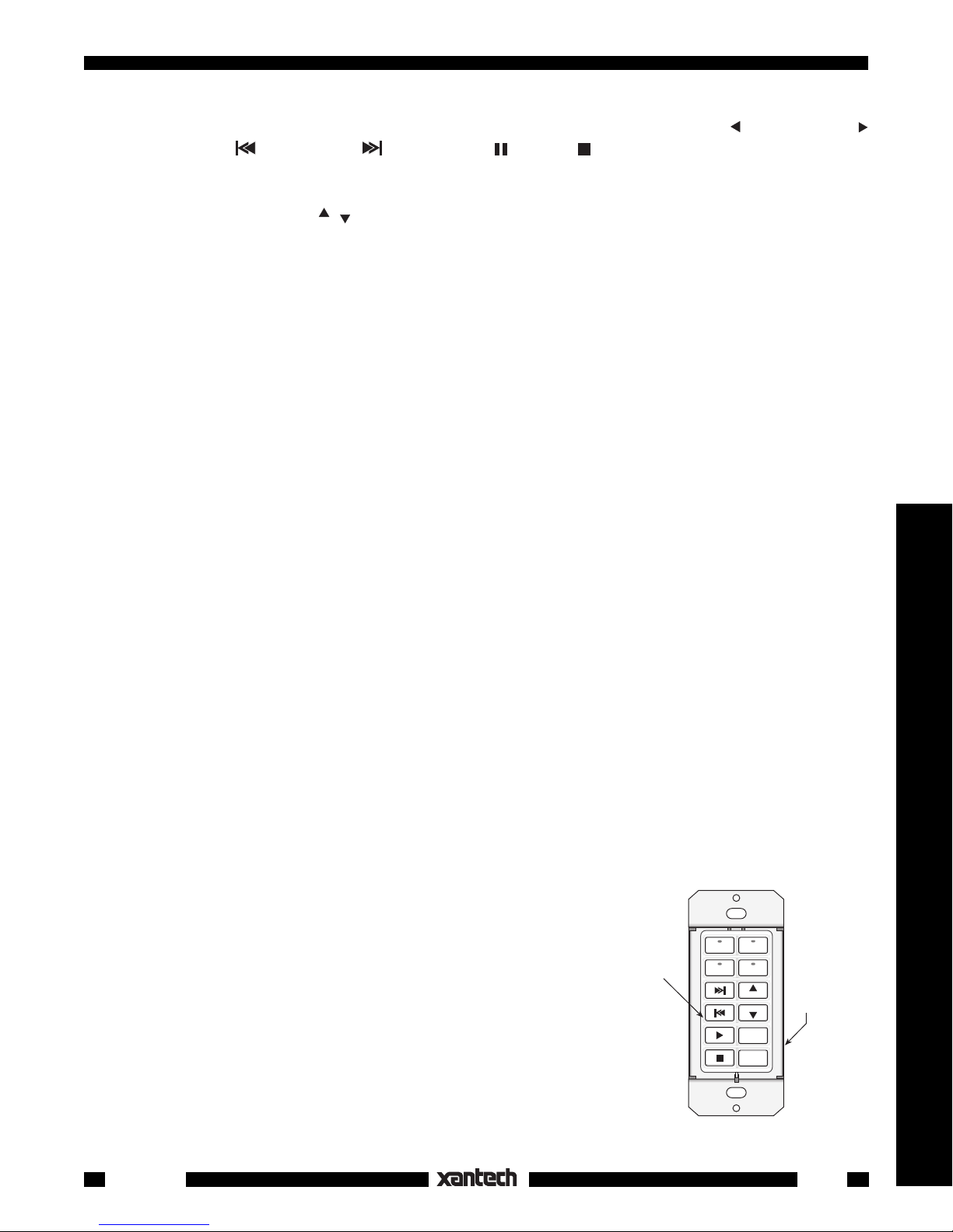
The next step is to determine what SmartPad3 modules and keypad buttons are required to perform this
job, as follows:
1. Since there are 4 sources, we can use the KM4 Key Module, which provides 4 sources with status
indicators and 8 function keys.
2. Now, since this is a 1-gang configuration, we need an LM110 Base Module into which we plug the
KM4, as shown in Fig. 5.
3. The next step is to determine exactly what buttons are needed to carry out the control functions
needed.
4. Again, we begin this process by assigning the Source buttons first;
CD1, TUNER, CD2 and TAPE. See Fig. 5.
5. Next, we assign the function control buttons based on the list of
functions given on page 12.
NOTE: Most of the buttons for steps 4 and 5 are provided in the
SOURCE and FUNCTION bags of buttons supplied with the KM4.
Buttons CD 1 and OFF are not supplied but are available separately
KM4
1
0
F
2
E
CD 1
WRITE
PROTECT
CD 2
COM PORT
TUNER
D
C
B
A
NETWORK
ADDRESS
NETWORK
RESTORE
3
4
5
6
7
9
8
TAPE
VOL
LM110
VOL
MUTE
OFF
WRITE
READ
from Xantech. They are listed in the dealer price list (along with all
buttons currently available for the SmartPad
system). They should
3
be ordered at the same time as the other keypad parts.
Fig. 5 Single Gang Button Assignments
Controllers
Smart Pad
3
7
Page 8
6. Now that all the buttons have been assigned (as shown in Fig. 5), it is necessary to assemble them
into the KM4 key module. Then insert the completed key module into the LM110.
See "Button and Module Assembly", page 18, for instructions.
NOTE: In this example the buttons are placed in what is considered an ergonomically pleasing
arrangement. Again, you may place the buttons in any arrangement you wish, to best fit taste and
application.
The only exception to this is the 4 source buttons. They need to be kept in the 4 upper locations in
order for the source indicators and bank selections to operate.
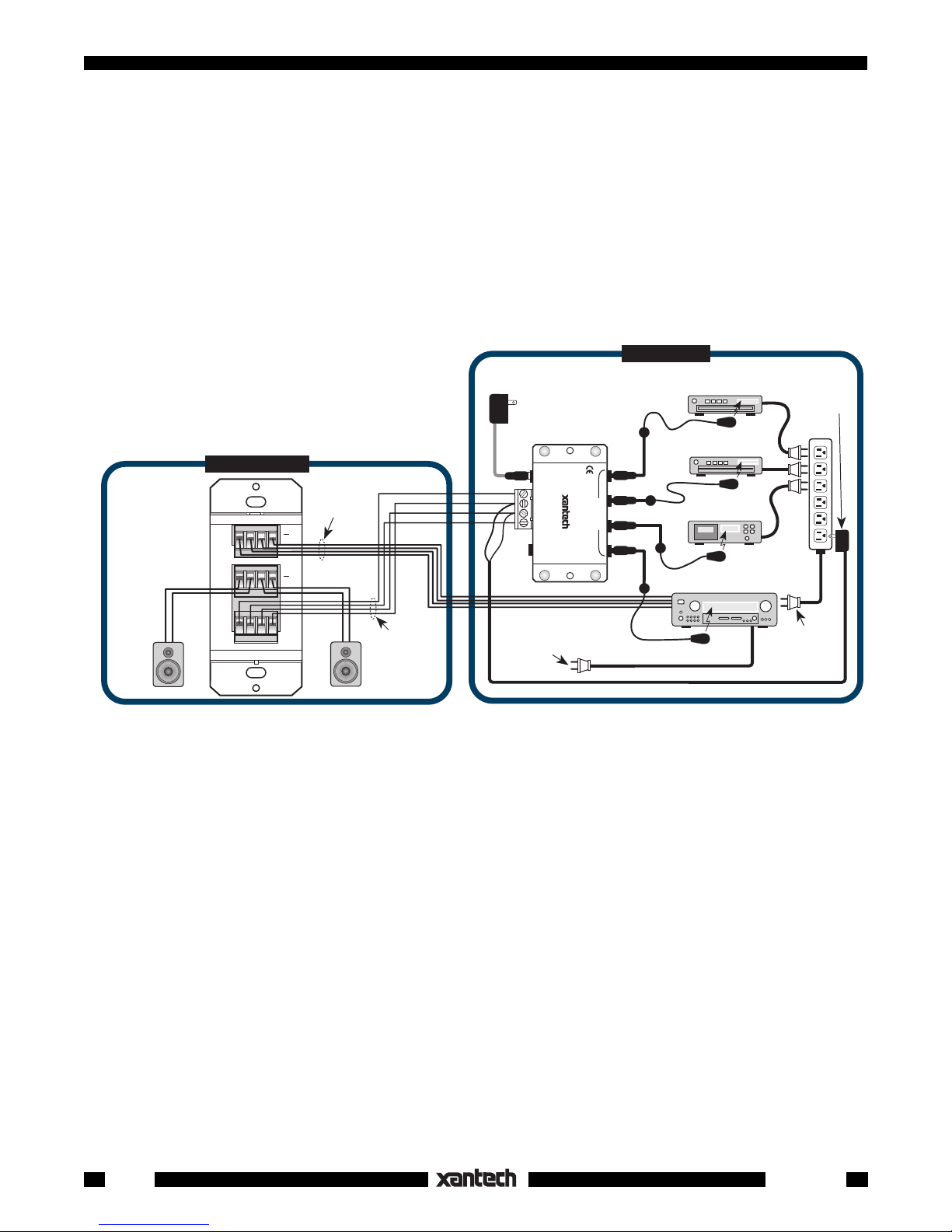
7. The keypad is now ready to be wired into the total system. See Fig. 6. Power may then be applied
and we can proceed with the Programming of each button.
MAIN ROOM
Power Supply
AC
Power
Strip
Plug into
Switched
AM/FM Receiver
on
786-00
(12V)
AC Outlet
Left
Speaker
REMOTE ROOM
+12V
4-Conductor
IN
AMPLIFIER
OUT
SPEAKER
Speaker Cable
Right
Speaker
LM110
SmartPad
(rear view)
L+ L-- R-- R+
Fig. 6 Typical Connection Diagram, Based on Client Specification, page 12.
GND
STATUS
OUT
4-Conductor
IR Signal Cable
781RG
Power Supply
To 120 V AC
(Unswitched)
Connecting Block
12VDC
+12 VDC
GND
STATU S
IR IN
+
–
RCVR
Power Cord for AM/FM
Receiver. Plug into an
Unswitched
789-44
CONNECTING BLOCK
®
IR
AC Outlet
789-44
EMITTERS
CD Changer
282M Mouse Emitter
DVD
282M Mouse Emitter
Cassette Deck
282M Mouse Emitter
AM/FM Receiver
282M Mouse Emitter
Programming a Single Gang Configuration
As mentioned on page 6, the LM110 must receive it's programming from a PM110 or Dragon Drop IR™.
(This means that you, the installer, must have a PM110 or Dragon Drop IR on hand, to program LM110's
for single gang applications). Before proceeding with this section, it is recommended that you read
"PROGRAMMING THE SMARTPAD
™ " section, where full programming details are given. The following
3
is a brief procedure, specific to this installation example.
NOTE: STATUS and AC power management are accomplished using sequenced commands and the
Switched AC Outlet on the AM/FM receiver. Refer to Fig. 6.
We'll begin by "teaching" commands to the 4 source (bank) buttons:
1. Insert the KM4, with selected buttons installed,
into the left bank
of a PM110. See Fig. 7.
2. Be sure the PM110 is powered, by wiring it to a connecting block same as shown in Fig. 3.
3. Press SEQ. The SEQ LED will flash.
4. Press CD1. CD1 LED will come on and the SEQ LED will come on steady.
NOTE: Turn the AM/FM receiver ON so that +12V is applied to the STATUS line. This ensures that
the source button LED's will light.
5. Point the AM/FM receiver remote at the IR window and press it's POWER key.
8
Smart Pad
3
Page 9

6. When the code is learned, the SEQ LED will
flash then go steady when you release the
POWER key on the remote.
7. Press DELAY. DELAY LED will flash. Press
DELAY once again to enter a 1 second delay.
(The 1 second delay allows some time for the
AM/FM receiver to power up to be sure it will
execute the CD source command).
8. Point the AM/FM receiver remote at IR window
and press it's CD1 (source) button.
9. When the CD1 code is learned, the SEQ LED will
flash then go steady when you release the CD1
key on the remote.
10. Press CNCL
twice to leave sequence mode.
PM110
KM4
CD 1
CD 2
TUNER
TAPE
VOL
VOL
MUTE
OFF
CNCL
STEP
XFER
M
PGM
CLR MEM RESTORE
FULL
SEQ
DELAY
EDIT
TRNS
DEL
ERR
IR
C
O
WRITE
PROTECT
NETWORK
0
F
E
D
C
B
A
9
NETWORK
ADDRESS
1
2
3
4
5
6
7
8
NOTE: Because we have fewer keys to work with in
a single gang configuration, we will use the CD1
Fig. 7 Programming a Single Gang using a PM110
button, on the 2nd tier, to provide the Disc+ function.
This means the user would 1st press CD1 button for less that 1 sec. to select the source. He could then
press the CD1 button for more than 1 sec. to cause the CD changer to step (or skip) forward one disc at
a time, as desired.
11. Press SEQ, then CD1, then CNCL, then CD1 again. This places you in the 2nd tier of CD1.
(See also Tiering, page 25).
12. Point the CD1 remote at IR window and press it's DISC+ or DISC SKIP button.
13. When the code is learned, the SEQ LED will flash then go steady when you release the key on the
remote.
14. Press CNCL
two times to exit the programming tier mode.
You can now test these learned commands. But first, be sure the AM/FM receiver's Power is turned OFF
and the emitters are placed on each of the components as shown in Fig. 6.
Using the same procedure, program the remaining source buttons. Just be sure to press the correct source
button in steps 4 & 11 above as you go from source to source. Remember that you do not need the
tier
command except for sources CD1 and CD2 (for DISC+).
As you complete each button, test it before going on. Repeat the procedure, as necessary, until correct
operation is obtained.
When the source buttons are complete, proceed to
PM110 LM110
program each of the 8 function buttons, using essentially the same steps as outlined for the 2-gang configuration, previous. The only difference is there are
fewer buttons involved. Also, the TUNER up/down
tuning commands need to be stored under the and
buttons on the TUNER bank.
NOTE: A 2nd tier could be added to the TUNER
button for AM/FM selection, if desired.
CD 1
CD 2
TAPE
MUTE
FULL
NETWORK
SEQ
DELAY
WRITE
1
0
F
2
E
3
D
4
C
EDIT
VOL
VOL
OFF
PROTECT
STEP
TRNS
DEL
XFER
ERR
IR
C
O
M
5
B
6
A
7
9
8
NETWORK
ADDRESS
COM PORT
PGM
CLR MEM RESTORE
CNCL
TUNER
UP
WRITE
PROTECT
COM PORT
UP
F
E
D
C
B
A
NETWORK
ADDRESS
NETWORK
RESTORE
1
0
2
3
4
5
6
7
9
8
Program Transfer
Now that programming is complete, we need to trans-
3' cable
fer the learned commands from the PM110 to the
LM110. Proceed as follows:
Fig. 8 PM110 to LM110 Program Transfer
Controllers
Smart Pad
3
9
Page 10

1. Using the 3' cable supplied with the PM110, simply plug it into the COM Port of each unit as shown
in Fig. 8.
2. Be sure both the PM110 and the LM110 are powered and that the LM110's WRITE PROTECT switch
is set to WRITE before proceeding.
3. Press XFER key on the PM110. The PGM and SEQ LEDs will flash.
4. Press PGM. The PGM and SEQ LEDs will continue to flash until the entire memory contents are
downloaded to the LM110.
5. Disconnect the 3' cable.
6. Remove the KM4 from the PM110 and insert it into the LM110.
The LM110 is now ready for final operation.
Note: If transfer does not complete or the ERR LED shows, remove power from both units, reapply
power and try again.
A Three Gang Configuration
For the client who wants to control a larger group of sources and functions than that permitted by two gangs,
it is necessary to move up to a three gang configuration of the SmartPad
. Again, let's assume the client
3
has the following equipment and system requirements:
1. An AM/FM receiver and 6 sources: TUNER (AM/FM), a CD changer, an LD (Laser Disc player), a
cassette TAPE deck, a SAT (Satellite receiver) and a VCR.
2. When a source button is pressed, it must turn on the AM/FM receiver and the associated source.
3. The keypad must have the following control function commands for each source:
TUNER: Tuner Up/Down (scroll of preset stations), AM/FM (select).
CD: Play, Scan Forward/Reverse, Track Forward/Reverse, Track select (using numeric entry), Disk
select (using numeric entry), Pause, Stop.
LD: Play, Scan Forward/Reverse, Chapter Forward/Reverse, Pause, Stop.
TAPE: Play Forward, Fast Forward/Rewind, Pause, Stop.
SAT: Menu, Guide, Cursor (Arrow) Keys, Channel Up/Down, Channel Select (using numeric entry)
and Recall (previous channel).
VCR: Play, Scan/Fast Forward/Rewind, Pause, Stop.
This is the basic client specification for this application of the SmartPad
3.
As with the previous configurations, the next step is to determine the SmartPad3 modules and keypad
buttons needed to perform this job. Using the client specification and similar procedures to those on pages
7 and 8, we have come up with the module and button assignments as shown in Fig. 9.
When making these choices, keep the following in mind:
1. Since both a numeric and a cursor module are
used, special consideration is needed to best
utilize the available function keys. For instance,
the CM1F cursor module was chosen for ease
of use with the SAT receiver. You will need,
however, to use these keys on the CD, LD,
TAPE and VCR banks to perform such functions as Track Forward/Reverse, Chapter Forward/Reverse, Scan/Fast Forward/Rewind, etc.
2. The numeric buttons can be used for direct
entry of AM/FM stations, disc and/or track
10
1
0
F
2
E
3
1 2
WRITE
D
4
TUNER
C
PROTECT
3 4
5 6
7 8
9 0
COM PORT
RECALL
B
NETWORK
ADDRESS
A
9
8
NETWORK
RESTORE
5
6
7
DISC
SELECT
A/B
GUIDE
KM1N
Fig. 9 3-Gang Module & Button Assignments
PM110EM110
PGM
CLR MEM RESTORE
CNCL
SEQ
DELAY
EDIT
STEP
TRNS
DEL
XFER
IR
C
O
M
TUNER
CD
FULL
NETWORK
LD
WRITE
PROTECT
TNR
ERR
MUTE
KM6
TAPE
1
0
F
2
E
3
D
4
C
5
B
6
VCRSAT
A
7
9
8
NETWORK
ADDRESS
VOLTNR
VOL
OFF
CM1F
Smart Pad
3
Page 11

selections on CD, Channel selection on SAT & VCR, etc., on
Rubber
Actuators
Key Module
Shell
Rear
Tab
Cursor
Buttons
Retainer
Tabs
18-Pin
Connector
Key Module
PCB & Base
Retainer
Slots
Function
Keys
Bank
(Source)
Buttons
their respective banks.
3. The
TNR
,
buttons for the AM/FM Tuner can also serve as
TNR
Channel Up/Down for SAT & the VCR TV tuner.
4. Use the 2nd tier on the TUNER button for AM/FM selection,
if desired.
PM110
(Rear)
PM110
TM
SMART PAD
3
PROGRAMMABLE MODULE
SPEAKER
AMPLIFIER
OUTPUT
INPUT
L+ L– R– R+
L+ L– R– R+
Red Stripe
TO EM110
+12V
IR OUT
STATUS
EM110
(Rear)
Red Stripe
TO PM1
10
GND
Programming a Three Gang
SYLMAR, CA MADE IN U.S.A.
Configuration
®
1. When you have completed the assembly of the buttons and
the modules and have installed them into the PM110 &
EM110 as shown in Fig. 9, connect them together with the
20-Conductor Ribbon Cable & Plug Ass'y (supplied with EM110)
Fig. 10 3-Gang EM110 to PM110 Connections
ribbon cable as shown in Fig. 10. Locate red stripe side of
cable as shown.
2. You can now program this configuration in the same manner as described in the procedures on pages
9 through 11.
3. When you have completed all programming, you can transfer this whole command set to any number
of additional keypads (identically configured), as needed, in multi-room installations. Refer to the
"Command Transfers (Cloning)" section.
BUTTON AND MODULE ASSEMBLY
The key module assemblies have been designed specifically so that they can be custom configured with
the desired button arrangements. To assemble, disassemble, change and reassemble, as desired,
proceed as follows:
Assembly
1. First, decide on the buttons you need and their locations (see
examples on pages 8,12 & 17).
2. Pick up the Key Module PCB & Base assembly and carefully
push each button onto the Rubber Actuators in the locations
you desire. Refer to Fig. 11.
(As received from the factory, the key module shell is separate
from the key module PCB & base assembly).
3. When the buttons are completely in place, pick up the Key
Fig. 11 Typical Key Module Assembly
Module Shell and lower it over the Key Module PCB & Base
assembly. (Figs. 11 & 12).
4. Move the buttons slightly, as necessary, to align them so
that they pass through the button openings in the Key
Assembled
Buttons
Key Module
Shell
Front
Tab
Module Shell.
5. Carefully press the Key Module Shell down until the 4
small Retainer Tabs (Fig. 11) on the Key Module PCB
& Base assembly snap into the corresponding Retainer
Slots on the Key Module Shell.
6. Mount the completed key module into the PM110 (or
LM110 or EM110). Place the Front Tab on the module
under the Small Lip of the PM110. Align the 18-pin plug
with the 18-pin socket and carefully push into place. See
Fig. 13.
Smart Pad
3
Key Module
PCB & Base
Fig. 12 Assembly of Key Module Shell
Rear
Tab
11
®
Controllers
Page 12

LM110,
PM110,
or
EM110
Base
Modules
Front
Tab
Rear
Tab
18-Pin
Socket
18-Pin
Plug
Key
Module
Small
Lip
Disassembly
You may find it necessary, from time to time, to disassemble the key
module to change buttons for system updates, etc. Proceed as follows:
1. Remove the key module from the PM110 (or LM110 or EM110) by
pulling upward at the 18-pin connector end of the module.
2. Grasp the key module with both hands, with the buttons facing
you. See Fig. 14.
3. With the fingers of each hand pull outward on the lower edges of
the key module shell.
4. As the 4 small retainer tabs recede from the slots on the sides of
the key module shell, press down on the buttons with your
thumbs.
5. The key module shell should now move away from the key
module PCB and base assembly.
CAUTION: To avoid damage, be sure not to use excessive force when executing this disassembly procedure.
6. When you have made the desired button changes, reassemble the unit using the steps given under "Assembly".
Fig. 13 Key Module Assembly to Base Module
PROGRAMMING THE SMARTPAD
The following procedures detail the overall programming capabilities of the SmartPad
. In general, the unit is capable of
3
™
3
Fig. 14 Key Module Disassembly
learning single, sequenced (macros) and tiered commands under each button for any of the keypad
configurations. The system supports up to a maximum of 8 banks (sources) whether one uses the single,
dual, or 3-gang configurations. The actual number of banks depends on the key modules you select for the
job. Allowable choices are 1, 2, 4, 6, or 8 banks.
A summary of the SmartPad
programming features are:
3
• Learns pulse or carrier IR type commands.
• Supports IR commands, "push & hold" tiering and sequence commands on any key.
• Commands storable into 1 to 8 banks, selectable by bank keys.
• Editing of command sequences.
• Intelligent Power Management [inhibits first command in a sequence (power On/Off) if STATUS
terminal sees +5 to +30V DC].
• Bank tracking signal switches all keypads to the same bank, irrespective of which keypad’s source
button is pressed (provided the keypads are on the same IR bus network).
• Network Addressing allows code transfer over the IR bus (network) from a programmed keypad to as
many as 16 keypads simultaneously.
• RS232 data compatible COM port permits cloning between keypads and from Dragon Drop IR™
software.
• Optional Windows based Dragon Drop IR™ software permits complete virtual keypad programming
on a PC with code transfer to individual keypads via the COM port.
• Speaker Relay programming.
• Code Group Programming.
• Bank Tracking Programming.
• User configurability of buttons into key modules and key modules into base units.
12
Smart Pad
3
Page 13

Button & LED Indicator Descriptions
The following small buttons and indicators are located on the PM110 in the space between the two gangs
and under the right key module as shown on page 6 and Fig 15. NOTE: Use a blunt tool to press
programming buttons, such as the tip of a 3.5mm mini plug.
1. PGM - Places the keypad in
PGM LED flashes when in
2. CNCL -
Cancels (exits) the various program-
Program Mode.
Program Mode.
ming modes. LED's will stop flashing.
3. FULL LED - Flashes when the user program
memory is full.
4. SEQ - Places keypad in
Sequence mode for
programming of command sequences (or macros).
SEQ LED flashes when in
Sequence Program-
ming mode.
5. DELAY - Adds timed
delays (1 to 30 seconds)
Do not use sharp objects!
1
2
PGM
CNCL
4
FULL
SEQ
5
DELAY
6
EDIT
7
STEP
TRNS
3
14
CLR MEM RESTORE
NETWORK
17
WRITE
PROTECT
NETWORK
ADDRESS
15
16
18
1
0
F
2
E
3
D
4
C
5
B
6
A
7
9
8
between commands in a Sequence, either during first programming of a Sequence or subse-
9
DEL
8
quent Editing of a Sequence.
XFER
DELAY LED flashes when in
6. EDIT - Allows
editing of existing sequences.
Delay Mode.
EDIT LED flashes when EDIT is first pressed.
10
13
ERR
11
IR
C
O
M
12
7. STEP - Steps through each command when
editing a Sequence (in EDIT mode).
8. TRNS LED - Lights steady during the interval
Fig. 15 Programming Buttons & Indicators
when IR commands are sent to the IR output line
for the controlled equipment. The TRNS (transmit) LED will light whether or not there is continuity in
the output circuit. It will not light with bank tracking codes coming from other keypads.
9. DEL DEL LED flashes when in
10. XFER - This key, with a subsequent press of the PGM key, initiates the
Deletes single, sequenced & tiered IR commands from any individual key.
Delete Mode.
transfer (cloning) of
programmed contents from one keypad to another via the COM Port connector. Also, pressing XFER
then SEQ, will initiate cloning to multiple keypads via the IR OUT (Network) line.
11. ERRor LED - Lights when an IR command cannot be learned correctly during the learning process.
12. IR - This
It
will not
Infrared sensor window receives IR commands from remote controls for programming only.
repeat commands through the network system.
13. COM Port - RS232 signal compatible port for uploading or downloading to/from a computer or
transferring programmed contents from one keypad to another.
14. CLR MEM - Clear Memory. Erases all user programmed commands when pressed twice within 1
second. Bank key flashes momentarily. Also restores all factory defaults for Speaker Relay, Code
Group and Bank Tracking Programming.
15. RESTORE - Resets unit to restart operation after errors, lockups, etc. Program key flashes
momentarily. Does not erase user programmed commands.
16. NETWORK LED - Flashes with any activity on the IR output line (IR commands being transmitted, bank
tracking codes, etc.).
Controllers
Smart Pad
3
13
Page 14

NOTE: The LM110 includes only a NETWORK LED and a RESTORE button. Refer to illustration on
page 6.
17. WRITE PROTECT Switch. Must be in WRITE position for all programming. PROTECT position
prohibits programming and protects all stored data from unintended erasure.
18. NETWORK ADDRESS - 16 position (0~F) switch allows up to 16 PM110/LM110 modules to have a
unique network address. Each module on a common IR bus (network) must be set to a unique network
address, prior to programming, to allow network cloning.
PROGRAMMING
Power Up: Begin by connecting the keypad to a typical system such as that shown in Fig 3. Be sure the
STATUS terminal is connected to +12V so that the source (bank) LEDs will light. Also, set the WRITE/
PROTECT switch to WRITE and the NETWORK ADDRESS to a
unique position
for each keypad used
in the system.
The following conditions are established when power is applied:
• The unit resets and operation begins.
• The keypad defaults to bank #1 (top left source button) after each power up.
• The unit is now ready for programming, communications with a PC or cloning of programmed contents
from one keypad to another.
Learning IR Command Codes
To teach IR commands to the unit, refer to Figs. 15 &
16 and proceed as follows:
1. Press the desired Source (bank) button. The
Source button LED will light.
2. Press the PGM (program) button. The PGM
LED will flash.
CAUTION: Use a blunt tool when pressing the
programming buttons, such as the tip of a 3.5mm
mini plug. Do not use pens, pencils, etc., as they
may damage or contaminate the switch material.
3. Now press the desired target key (one of the
Function or Source buttons).
With the target button selected and the PGM
LED has stopped flashing, you are ready to input
the IR command from the handheld remote
control.
NOTE: If you change your mind and wish to
teach a different button than the one you just
selected, simply press CNCL once, and press
the other button.
Function
Buttons
Fig. 16 Programming, Source &
Function Buttons
Programming
Buttons
PGM
CNCL
FULL
SEQ
DELAY
EDIT
STEP
XFER
C
O
M
PROTECT
TRNS
DEL
ERR
IR
Source (Bank)
CLR MEM RESTORE
NETWORK
WRITE
F
E
D
C
B
A
NETWORK
ADDRESS
Buttons
1
0
2
3
4
5
6
7
9
8
Function
Buttons
4. With the remote pointed at the IR window (1 to 2 inches away), press the key on the remote that has
the command you want to save.
The PGM & SEQ LED's will flash while storing. When storing is complete, the PGM LED will flash again
by itself.
NOTE: If the ERR (error) LED flashes, an error has occurred during programming (such as holding
the handheld remote too far away from the keypad, for example), indicating the unit has not learned
14
Smart Pad
3
Page 15

the command successfully. If this happens, wait for the PGM LED to come back on steady and repeat
step 4.
5. Now that the PGM LED is flashing again, press another target button and input another IR command.
When you are done learning commands, press CNCL (cancel) to exit the PGM mode. The PGM LED
will go off.
CAUTION: You must leave the PGM mode by pressing CNCL (press twice if in SEQ mode) before
programming a different source (bank).
NOTE: If you are using a STATUS Jumper (Fig. 17) or programming for a ZPR68,
for you to program Source commands twice into each bank
, using the SEQ (sequence) button, in order
it will be necessary
for the Source commands to operate.
Sequence Programming (Macros)
You can teach more than one IR command per button by using the Sequence Programming feature. This
permits several commands to be executed by one key press to carry out a macro of several system
functions. To teach a sequence of commands to a single button, do the following:
1. Press the SEQ (sequence) button. The SEQ LED will flash.
2. Now press the desired target button just as when doing regular IR programming. (This can be a Source
or a Function button). The SEQ LED will come on steady to indicate that it is ready for IR input.
3. Point the remote at the IR window (1 to 2 inches away) and press the key on the remote that has
the command you want in the sequence.
4. When the command has been learned, the SEQ and PGM LEDs begin flashing and continue to flash
until you release the key on the remote.
5. The SEQ LED will then turn on steady again to show that it is ready for another command.
Controllers
6. Repeat these steps for as many IR commands
as you want in the sequence.
7. When finished, press the CNCL key. The SEQ
LED will flash, indicating that a different Source
or Function button may be selected to enter
another sequence (repeating the steps above).
8. To exit the sequence mode completely, press
CNCL two times. The SEQ LED will go out.
Power Management
Normally you want a power command under each
Source (bank) button so that the system is turned ON
no matter which Source button is pressed. However,
without Power Management, pressing a 2nd Source
button would send out a 2nd power command, turning
the system OFF.
• The SmartPad
power management system pre-
3
vents this by stopping the first command in the
sequence (the power command) when the STATUS terminal is High (+5 to +30V DC).
• Similarly, when the system is OFF, the first
command (power) will be sent since the STATUS terminal is Low (0V).
• This assumes that a High and a Low voltage,
representing the ON and OFF condition of the
PM110
(Rear)
Connecting
Block, Zone
Controller, etc.
To Input of
PM110
SMART PAD
PROGRAMMABLE MODULE
TM
3
TO EM110
STATUS JUMPER
(see NOTE, page 25)
AMPLIFIER
INPUT
L+ L– R– R+
®
Fig. 17 Status Jumper Required When Power Management is Not
Used
SPEAKER
OUTPUT
L+ L– R– R+
SYLMAR, CA MADE IN U.S.A.
+12V
IR OUT
STATUS
GND
Smart Pad
3
15
Page 16

system or zone, is applied to the STATUS terminal on the rear of the keypad.
• See Figs. 3 and 6 for typical connections for STATUS operation.
To take advantage of power management, program two or more sequence steps on each Source button.
Typical command sequences, with
Power first
, might be as follows:
a) TUNER Source Sequence (3 steps):
Power, Delay, Tuner (source)
b) CD Source Sequence (4 steps):
Power, Delay, CD (source), Play (CD play)
NOTE: If power management is not used (i.e. 3-wire hookups), a short jumper must be connected between
the STATUS and +12V terminals (see Fig. 17).
This powers the source button LEDs so they will come on with the selected bank. In this case, you must
put the system power command under an ON/OFF button (not under the source buttons).
then need to make two initial button presses, one for ON and one to select the Source
The user will
. (See also
NOTE top of page 24).
CAUTION: ZPR68 Installers. When programming the SmartPad3 for control of a ZPR68, you will need
to place the source select commands twice under each source button (in a 2-step sequence)
. This
permits sources to be selected after zone turn-on. (They would otherwise be blocked when zone turn-on
drives the STATUS line high).
Tiering
The SmartPad
has the ability to program sequences or single commands onto two tiers or levels on any
3
Source or Function button. The 2nd tier is accessed by a "Push & Hold" of the tiered button. This is very
useful when working with a limited number of buttons, such as single gang applications of the SmartPad3.
• After tiering is programmed, the 1st tier is activated when the button is pressed for less than 1 second.
• The 2nd tier is accessed by a "Press & Hold" of the same button for more than 1 second.
• The 1st tier would typically be used to perform
an initial function, such as power on, source
selection, track skip, etc.
Function
Buttons
Programming
Buttons
Source (Bank)
Buttons
• The 2nd tier would typically be used for a
secondary function that is related to the first tier,
such as music scan tiered on a track skip button
for CD.
1. To program the 1st tier of a button, simply
program a single command or a sequence following steps 1 to 6 under "Sequence Programming" (page 24).
2. Press CNCL once to end the sequence, then
again
press the designated target key
in order
to activate the 2nd tier. (If a 2nd tier is not
desired at this point, press CNCL a second time
to exit the Sequence mode. The key will then
CNCL
STEP
XFER
C
O
M
PGM
SEQ
DELAY
EDIT
DEL
IR
FULL
TRNS
ERR
CLR MEM RESTORE
NETWORK
WRITE
D
C
PROTECT
NETWORK
ADDRESS
1
0
F
2
E
3
4
5
B
6
A
7
9
8
default to single tier operation).
3. Once in the 2nd tier, program the desired com-
mand or sequence (with delays if needed, following steps 2 to 6 below). When finished, hit
CNCL
twice
to exit.
Fig. 18 Programming Reference
Function
Buttons
16
Smart Pad
3
Page 17

Programming Delays
Some IR controlled units may require an increased time interval between certain commands, particularly
between a Power ON command and a Play command, for instance, to operate correctly.
• When programming sequences, you can place delays between such commands so that sufficient time
is given for all functions to execute.
• The SmartPad
allows the insertion of timed delays at any point within a sequence. Proceed as follows:
3
1. Press the SEQ button to enter commands as described under Sequence Programming .
2. Just before you enter a command that requires a delay, press the DELAY button to enter the DELAY
mode. The DELAY LED will flash.
3. Now press the DELAY button, successively, to enter the number of seconds of delay you want. (Each
after
press of the DELAY button,
NOTE: The SmartPad
system already includes a 1/3 second interval between each command placed
3
the initial press, adds 1 second, up to a maximum of 30 seconds).
in a sequence. Each second you add will be in addition to the 1/3 second that already exits.
once
4. Press CNCL
to exit from DELAY mode and return to Sequence mode.
5. Next, enter the command that requires the delay. Continue programming the remaining commands
you desire in the sequence. Just before entering another command requiring a delay, repeat steps 2,
3 and 4 above.
twice
6. When finished with the sequence, press CNCL
. The delay times entered are now stored as part
of the sequence.
Sending IR Commands
Once you have “taught” the desired IR commands and/or sequences to the keypad, and have pressed
CNCL to leave the programming modes, you may send them to the controlled equipment simply by pressing
the key that relates to them. It is recommended that you test each set of commands you have placed in a
bank before proceeding to the next bank.
Deleting Commands
If you want to delete a command or sequence from any button, simply do the following:
1. Press the DEL (delete) button. The DEL LED will flash.
2. Press the target button that has the command(s) you wish to delete. The DEL LED will come on steady.
3. When erasure is complete, the DEL LED will resume flashing. If you wish to delete from other buttons,
you can do so now by repeating the procedure from step 2.
and
NOTE: One press of the target key will delete all commands in a sequence
on the 2nd tier (if used).
If you want to delete or change individual commands in a sequence, you must do so in the Sequence
Editing mode.
4. When done, press CNCL to exit delete mode. The DEL LED will go out.
Sequence Editing
Long sequences (probably with some delays interspersed between commands) will likely have to be edited
and experimented with to achieve correct timing control of the associated equipment.
• Editing is done in the EDIT mode using the STEP, DELete, PGM and DELAY buttons.
• It is best to think of the command sequence as a set of items laid end to end. When you activate the
EDIT mode, it sets the edit pointer to the front of this string of items.
• You use the STEP key to individually transmit and step through each command in the sequence. This
lets you see which commands are where, if all are working correctly, etc.
• If you activate a command that does not work or is incorrect, you can press the DEL key to remove
it and then the PGM key to store a new command in its place.
Controllers
Smart Pad
3
17
Page 18

• Additionally, you may insert delays into the sequence, as needed, for slow responding equipment.
• In this way you can work through the entire sequence, fixing problems as you go.
To edit a sequence, proceed as follows:
1. Press the EDIT key. The EDIT LED will flash.
NOTE: If you press the EDIT button and then change your mind or want to exit the operation at any
time, press the CNCL button twice.
2. Press the button having the sequence you wish to edit. The EDIT LED will go on steady. This indicates
that the sequence is open for editing. The edit pointer (insertion point) will be at the first item in the
sequence.
3. Press the STEP key to preview the first command in the sequence.
4. The command transmits. Watch to see what happens with the controlled unit. (Note: The TRNS LED
lights during transmit).
5. The edit insertion point will now be positioned in front of the next command in the sequence.
Deleting a Command Within a Sequence
6. If the command you just transmitted did not work and you wish to delete it, press the DEL button. The
DEL LED lights, then goes out, indicating the command has been deleted.
You may now STEP to the next command.
The DEL button will always delete the command that was last transmitted.
Inserting a Command
7. To insert a new or replacement command, press the PGM button. The PGM LED will come on steady.
8. Input the IR command in the normal manner.
9. When stored, the PGM and SEQ LED will flash, then go out. You may now STEP to the next command.
NOTE: You do not have to delete anything to add a new command to the sequence.
Inserting a Delay
A delay may also be inserted in a similar manner.
10. Step through the sequence to a place just ahead of the command where you wish to insert a delay.
11. Press the DELAY button. The DELAY LED will light.
12. Enter the desired delay time (see Programming Delays, step 3).
13. Press CNCL once to exit delay mode. The DELAY LED will go off indicating the delay is now stored.
You may now STEP to the next command.
NOTE: If you wish to step through the sequence again for further checks and editing, you will need
to repeat the editing process from step #1.
When you have finished editing, press CNCL twice to exit the EDIT mode. You may now press the edited
button to check for proper operation.
Editing the 2nd Tier
14. Press CNCL, CNCL, EDIT, target button, CNCL, target button. You are now in the 2nd tier.
15. Edit this tier in the same manner by following steps 3 through 13.
Speaker Relay
Each of the PM110 and LM110 modules has a speaker relay built into it permitting local speakers to be
muted independently of speakers in other rooms. The relays are controlled in two ways - internally coded
(non-IR) to any desired button on the keypad and with Xantech RC68+ (or RC68) Programmer (optional)
IR commands. The IR codes can be taught to a learning remote or to a keypad, if desired.
18
Smart Pad
3
Page 19

Programming for the Speaker Relay
The relay will respond to commands for MUTE ON (sound off),
MUTE OFF (sound on), and MUTE TOGGLE. Since the relay is
switching speakers in the local room where the ON/OFF condition is
audibly discerned, the MUTE TOGGLE command would most often
be used. However, the MUTE ON and MUTE OFF (pair) commands
RC68
(rear
panel)
0
1
F
E
D
C
B
8
A
9
0
1
F
E
D
C
B
8
A
9
1st Digit
2
7
2
7
(Left on
3
RC68+,
4
5
Upper on
6
3
6
4
5
RC68)
2nd Digit
(Right on
RC68+,
Lower on
RC68)
are also made available, to allow a user to control other rooms (i.e.,
children's rooms) from a central location (i.e., parent's room) with a
Fig. 19 FA Setting for Speaker Relay Coding
known ON or OFF condition.
To code the keypads to receive unique RC68 commands, proceed as follows:
1. Connect the keypads for the zone onto a common IR bus (network) along with an IR receiver as shown
in Fig. 20. Be sure the system is powered.
LM110
Smart Pad
(rear view)
L+ L-- R-- R+
VGGS
RC68 or RC68+
Handheld Programmer
VGGS
1
REMOTE ROOM
LM110
Smart Pad
(rear view)
IN
AMPLIFIER
OUT
SPEAKER
4-Conductor IR
Bus (network) Cables
(home runs)
CB18 Strip-IR™
Parallel Connecting Block
VGGS
234567
RC68 PROGRAMMER
VGGS
7
E-FLAT LAST MAX-V TRIM
OFF
60 88 18 98
08 A8 38 B8
28 E8 78 F8
68 C8 58 D8
BALANCE
Z-ADJ
ON OFF
MUTE
20 E0 70 F0
00 C0 50 D0
40
1
5678
A0 30 B0
2
GLOBAL
34
0123456
10
ABC
48
01 90
L+ L-- R-- R+
VGGS
IN
AMPLIFIER
OUT
SPEAKER
VGGS
Micro Link™IR Receiver
VGGS
VGGS
490-00
REMOTE ROOM
LM110
Smart Pad
(rear view)
L+ L-- R-- R+
To System
"STATUS" Voltage
(+)(–)
VGGS
98
IN
AMPLIFIER
OUT
SPEAKER
12VDC
+12 VDC
GND
STATUS
IR IN
RCVR
IR
REMOTE ROOMREMOTE ROOM
AMPLIFIER
INPUT
L+ L– R– R+
CONNECTING BLOCK
789-44
EMITTERS
®
PM110
Smart Pad
(rear view)
SPEAKER
OUTPUT
L+ L– R– R+
782-00
Power
Supply
To Emitters on
TO EM110
+12V
IR OUT
Controlled
Components
STATUS
GND
To 120 VAC
(Unswitched)
Controllers
Fig. 20 Network Connection Diagram
2. If you have not already done so, set each SmartPad
1, 2, 3, etc. (Fig. 21).
3. Set the WRITE/PROTECT switch to WRITE on the 1st keypad (i.e., the PM110 keypad with Network
Address 0) and press RESTORE button.
4. Set the rear switches on the back of an RC 68 or RC68+ to FA.
5. Direct the RC68 toward the IR receiver and press it's upper left-most key. See Fig. 22.
6. The active Source (bank) button LED on the SmartPad
Smart Pad
3
to a unique NETWORK ADDRESS such as 0,
3
will flash four times.
3
19
Page 20

ON/TOG OFF0ON/TOG OFF
1
ON/TOG OFF2ON/TOG OFF
3
ON/TOG OFF4ON/TOG OFF
5
ON/TOG OFF6ON/TOG OFF
7
ON/TOG OFF8ON/TOG OFF
9
ON/TOG OFFAON/TOG OFF
B
ON/TOG OFFCON/TOG OFF
D
ON/TOG OFFEON/TOG OFF
F
I
#0 ON/ TOG Button
with Code Group FA
initiates Relay Mute
Coding Procedure.
(Step 5)
These numbers,
0~F, represent
16 addresses 0~F
on SmartPad3's.
Use I Overlay
There is an
ON/TOG and
an OFF
IR command
assigned for
each address.
Code Group
D8 (default).
The 1st SmartPad
the MUTE ON and MUTE OFF buttons (pair) you
selected on the SmartPad3.
It will also respond, over the IR network, to the #0 ON/
TOG and OFF IR commands from the RC68+ (or
RC68) set to the default Code Group D8. Refer to
Figs. 22 & 23.
10. Pressing the #0 ON/TOG IR command on the
Programming the remaining SmartPad
Each remaining keypad will need to respond to unique
muting commands, otherwise muting one room on the
IR network with the RC68 IR commands, will mute all
the rest as well.
Since any PM110 can store unique coding for up to 16
addresses, we will use the 1st keypad to program
codes for the rest, as follows:
11. On the 1st keypad (PM110), change the NET-
12. Repeat steps 4 through 8.
13. Repeat steps 11 and 12 for each of the remain-
At this point the coding that causes each keypad to respond to its own mute buttons and to the unique RC68
commands over the IR Network, for each keypad address, is stored in the 1st keypad. To transfer this coding
to the rest of the keypads, do a Network Transfer as follows:
14. Set the WRITE PROTECT switch to the WRITE position and press RESTORE on all keypads.
7. Within 3 seconds, press the button on the
SmartPad3 where you want Relay Mute ON (i.e.
a MUTE ON button. See Fig. 24). The active
Source button LED will flash twice to confirm
your action.
8. Again, within 3 seconds, press the button on the
SmartPad
where you want Relay Mute OFF
3
(i.e. a MUTE OFF button). The active Source
button LED will flash twice to confirm your
action followed by four flashes to indicate the
end of Relay Mute programming for Address 0.
has now been coded to respond to
3
9. Test the IR commands by setting the rear
switches on the RC68 to D8 (the factory default
Code Group setting for the SmartPad
).
3
RC68 should cause the Relay to MUTE ON (if
OFF). Pressing the #0 OFF button should cause
the Relay to MUTE OFF (if ON). Refer to Fig. 22.
's
3
WORK ADDRESS switch to match an address
of the next keypad in the system (i.e., 1) then
press RESTORE on the 1st keypad.
ing addresses you have for the rest of the Smart
's.
Pad
3
IMPORTANT: You
11.
must
press RESTORE each time you change the NETWORK ADDRESS in step
KEYPAD #1
(PM110)
WRITE
PROTECT
Address 0
Fig. 22
RC68+ With Overlay I for
Relay Mute Programming.
(RC68 works also, but the I
Fig. 23
D8 Default
Code Group
Setting for
SmartPad
0
1
F
2
E
3
D
4
C
5
B
6
A
7
9
8
NETWORK
ADDRESS
Set Each Keypad to a Unique Network Address
3
KEYPAD #2
(PM110 or LM110)
WRITE
PROTECT
RC68
(rear
panel)
Address 1
Fig. 21
F
E
D
C
B
A
NETWORK
ADDRESS
KEYPAD #3, etc.
(PM110 or LM110)
0
1
2
3
6
7
9
8
E
D
C
E
D
C
WRITE
4
5
PROTECT
Address 2, etc.
0
1
2
F
3
4
5
6
7
B
8
A
9
0
1
F
B
8
A
9
2nd Digit
2
3
4
5
6
7
NETWORK
ADDRESS
1st Digit
(Left on
RC68+,
Upper on
RC68)
(Right on
RC68+,
Lower on
RC68)
0
1
F
2
E
3
D
4
C
5
B
6
A
7
9
8
20
Smart Pad
3
Page 21

15. Press XFER, then SEQ on the 1st keypad.
The SEQ, PGM and NETWORK LED's will blink until the transfer completes. (On LM110's the Source
and NETWORK LED's blink).
16. You may now test the Mute buttons that you chose on each keypad to determine proper functioning.
Refer to Fig. 24.
Also, test each unique IR command from the RC68 (refer to steps 9, 10 and Fig. 22) to see that each
keypad's relay responds individually and correctly.
NOTE: The active Source (bank) LED will blink Off every 2 seconds to remind you when the relay is
in the MUTE ON mode.
17. The final step would be to teach the related RC68 ON/TOG and OFF IR commands into learning
remotes, such as URC-2's, dedicated to each room.
18. A master SmartPad
could also be programmed (on different buttons than its own relay muting) for
3
control of ON/OFF relay muting in a different (i.e. child's) room.
Programming for the TOGGLE command only
If you do not need the MUTE ON & MUTE OFF
(paired) commands, you can simplify the process.
The single TOGGLE command, for instance, would
work well under the MUTE button in a system such as
that in Figs. 5 & 6. To program Toggle only, proceed
as follows:
19. Begin by following steps 1 through 7.
20. At this point, simply wait for the active Source
button LED to flash twice, then four times,
without
pressing any more than one key on
Press for
MUTE OFF
(sound ON)
Press for
MUTE ON
(sound OFF)
WRITE
1
0
F
2
E
3
TUNER
CD
D
4
C
5
B
6
A
7
9
WRITE
PROTECT
MUTE
OFF
MUTE
ON
NETWORK
ADDRESS
COM PORT
8
NETWORK
RESTORE
VOL
VOL
OFF
READ
WRITE
READ
CD 1
WRITE
PROTECT
CD 2
NETWORK
ADDRESS
COM PORT
0
F
E
TUNER
D
C
B
A
9
NETWORK
RESTORE
1
2
7
8
TAPE
VOL
VOL
MUTE
OFF
3
4
5
6
Press for
MUTE
TOGGLE
SmartPad3. The SmartPad3 will now only respond to the Relay MUTE TOGGLE command
from that one key. See Fig. 24.
21. Now follow steps 11 through 16 to program the
remainder of the Smart Pad
's.
3
Remember, in step 11, to select a different
Programming for separate
MUTE ON and OFF
(two button
paired commands)
Programming for
MUTE ON/OFF
(single button
toggle command)
Fig. 24
Typical Selection of Mute Buttons on SmartPad3 for Relay Paired or
Toggle Mute Commands.
Address each time and press the RESTORE key.
22. Transfer the programmed contents from the 1st keypad to the rest per steps 14 ~ 16.
23. The final step would be to teach the related RC68 ON/TOG (Toggle) IR command into learning
remotes, such as URC-2's, dedicated to each room.
NOTE: The internally coded (non-IR) Relay Mute commands are active on tier 1 only. You can, however,
program other product IR commands on both tier 1 and 2 on the same Relay Mute button.
Code Group Programming
The SmartPad
, like certain other Xantech products, has the ability to be set to various IR Code Groups.
3
This allows all keypads on the same zone (IR Network) to respond individually to Bank Tracking and
Speaker Relay commands, if needed. This means that a keypad that has been changed to a different Code
Group will not bank track with others unless they are also changed to the same Code Group. Speaker Relay
commands will need to be set up using the new Code Group as well and will therefore operate independently
of other keypad Speaker Relays.
CAUTION: Unless you have a very specialized application, it is recommended that you do not attempt to
change the Code Group from the factory default setting of D8.
If needed, however, change the Code Group as follows:
Controllers
Smart Pad
3
21
Page 22

1. Connect the keypads for the zone onto a common IR bus (network) along with an IR receiver as shown
in Fig. 20. Be sure the system is powered.
2. If you have not already done so, set each SmartPad
to a unique NETWORK ADDRESS such as 0,
3
1, 2, 3, etc. (Fig. 21).
3. Set the WRITE/PROTECT switch to WRITE on the 1st keypad (i.e., the keypad with Network Address
0) that you wish to change and press the RESTORE button.
4. On all the other keypads, set the WRITE/PROTECT switch to PROTECT.
5. Set the rear switches on the back of the RC 68 or RC68+ to FF.
6. Direct the RC68 toward the IR receiver and press a key that reflects the desired Code Group.
CAUTION: Do not choose a Code Group that is the same as other Xantech products that you may have
in the same IR system.
7. The active Source (bank) button and NETWORK LED's on the SmartPad
will flash once indicating
3
that the change has taken place.
8. Repeat steps 3 through 7 for any additional keypads you wish to change.
The factory default value of D8 can always be returned to by pressing D8 in the above process or by doing
a CLR MEM (Fig. 15). Be aware that CLR MEM will erase all user programming!
Bank Tracking Programming
Each Source (bank) key of the SmartPad
can be programmed to output one of up to 16 different Bank
3
Tracking commands. This is useful if you want a different arrangement of source buttons in one room
compared to another but still retain bank tracking between them, or to work more logically with the fixed
source keys of a handheld learning remote. To program different tracking commands, proceed as follows:
KEYPAD #1
(PM110)
WRITE
PROTECT
Address 0
KEYPAD #2
(PM110 or LM110)
0
1
F
2
E
3
D
C
B
6
A
7
9
8
NETWORK
ADDRESS
Set Network Address & Write/Protect Switches
WRITE
4
5
PROTECT
Address 1
Fig. 25
0
1
F
E
D
C
B
A
9
8
NETWORK
ADDRESS
2
6
7
3
4
5
(PM110 or LM110)
PROTECT
KEYPAD #3, etc.
WRITE
Address 2, etc.
F
E
D
C
B
A
NETWORK
ADDRESS
RC68
0
1
2
7
9
8
3
4
5
6
Fig. 26
FB Setting for
Bank Track Changes
(rear
panel)
1st Digit
(Upper)
2nd Digit
(lower)
0
1
2
F
E
D
C
7
B
8
A
9
0
1
2
F
E
D
C
7
B
8
A
9
1st Digit
3
4
5
6
3
4
5
6
(Left on
RC68+,
Upper on
RC68)
2nd Digit
(Right on
RC68+,
Lower on
RC68)
1. Connect the keypads for the zone onto a common IR bus (network) along with an IR receiver as shown
in Fig. 20. Be sure the system is powered.
2. If you have not already done so, set each SmartPad
to a unique NETWORK ADDRESS such as 0,
3
1, 2, 3, etc. See Fig. 25.
3. Set the WRITE/PROTECT switch to WRITE on the 1st keypad (i.e., the keypad with Network Address
0) that you wish to change and press the RESTORE button.
4. On all the other keypads, set the WRITE/PROTECT switch to PROTECT. See Fig. 25.
5. Next, press the Source (bank) key you wish to change.
6. Set the rear switches on the back of the RC 68 or RC68+ to FB per Fig. 26.
At this point, 16 default codes are available for rearrangement, if needed, labeled on the surface of the
buttons on the RC68 or RC68+ as 10 (80 on RC68+), 48, 01 (10 on RC68+), 90, 00, C0, 50, D0, 40,
A0, 30, B0, 20, E0, 70, & FO. See Fig. 27.
The first 8 relate, in left to right order, to the 2, 4, 6 & 8 banks currently available on the SmartPad
key
3
modules (KM2, KM4, KM6 & KM8). Refer to Fig. 27.
Use the first 8 when you want to make bank tracking changes so that source tracking will agree
between keypads with different source button arrangements.
Use the 2nd 8 if you want to bank track between certain keypads but not with the others.
22
Smart Pad
3
Page 23

7. Direct the RC68 toward the IR receiver and
press a key that reflects the desired choice.
The active Source (bank) button and NETWORK
LED's on the SmartPad3 will flash once indicat-
ing that the change has taken place.
8. Repeat steps 3 through 7 for any additional
source buttons you wish to change.
The factory default set of tracking codes can always
be returned to by reprogramming the 10 through D0
codes in order using the above process or by doing a
CLR MEM (Fig. 15). Be aware that CLR MEM will
erase all user programming!
1st 8
codes
2nd 8
codes
ABC
10
1
00 C0 50 D0
5678
40
20 E0 70 F0
60 88 18 98
08 A8 38 B8
28 E8 78 F8
E- LAST MAX- TRIM
68 C8 58 D8
OFF
01 90
48
34
2
A0 30 B0
GLOBA
Z-ADJ
OOF
BALANCE
Bank 1 code
Bank 2 code
Bank 3 code
Bank 4 code
Bank 5 code
Bank 6 code
Bank 7 code
Bank 8 code
KM8
RC68 and
RC68+ Keys
Fig. 28 will serve to illustrate a typical example.
• Keypad #1 is a simple 2-source version, using a
KM2.
• Keypad #2, in another room, has 4 sources using a KM4, with CD and
TUNER in different locations.
• To have the CD and TUNER sources bank track correctly between
Fig. 27 Default RC68 Bank Tracking Codes
CD
Bank 3 code (01)
Bank 4 code (90)
TUNER
VCR
SAT
CD
TUNER
the two keypads, all that is needed is to place the Bank 3 code (01
from the RC68) into the CD bank of the #1 keypad and Bank 4 code
(90 from the RC68) into the TUNER bank of the #1 keypad.
• To do this, follow the previous procedure, steps 1 through 8.
• Now, pressing CD or TUNER on either keypad will result in them
tracking together.
MUTE
OFF
KEYPAD #1 KEYPAD #2
Fig. 28 Bank Tracking Example
KM2
VOL
VOL
KM4
MUTE
VOL
VOL
OFF
Command Transfers (Cloning)
All the commands stored in a PM110 may be transferred to another PM110 (or to an LM110 where
applicable) in two ways - via the COM Ports or by Network Transfer.
COM Port Transfer
You would do a COM Port transfer when you need to clone one keypad at a time. This would apply to zoned
systems where the keypads are not connected on a common IR bus (network) but you want each keypad
programmed identically. Proceed as follows:
1. Using the 3' cable supplied with the PM110, simply plug it into the COM Port of each unit as shown
in Fig. 29.
NOTE: You can make transfers with or without the key modules installed on the PM110's.
both
2. Be sure
units are powered before proceeding.
3. Set the WRITE/PROTECT switch to the WRITE position on the unprogrammed unit. Fig. 29.
NOTE: Transfers can be made from the programmed unit with its WRITE PROTECT switch set to
either the PROTECT or WRITE position. However, it is recommended that it be set to the PROTECT
position to prevent unintended alteration or erasure of programmed contents.
4. Press the XFER button on the programmed unit. Both PGM and SEQ LEDs will flash.
5. Press the PGM button. The PGM and SEQ LEDs will flash while a copy of the memory contents are
transferred to the unprogrammed unit. You may "clone" as many keypads as desired by repeating this
process.
NOTE: If transfer does not complete or the ERR LED shows, remove power from both units, reapply
power and try again.
Controllers
Smart Pad
3
23
Page 24

6. When done, set the
WRITE/PROTECT
switch to the PROTECT
position on all keypads.
Network Transfer
Network Transfer greatly facilitates the cloning of keypads
when you have a number of
keypads on the same IR bus
(network), up to a maximum of
16. This would apply to multi-
RANDOM
DISC–DISC
PGM
C
O
M
SEQ
DELAY
EDIT
TRNS
DEL
IR
FULL
ERR
CLR MEM RESTORE
NETWORK
WRITE
PROTECT
NETWORK
ADDRESS
1
0
F
2
E
3
D
4
C
5
B
6
A
7
9
8
COM PORTS
RANDOM
DISC–DISC
CNCL
STEP
A/B
XFER
+
PGM
C
O
FULL
SEQ
DELAY
EDIT
TRNS
DEL
IR
PROTECT
ERR
CLR MEM RESTORE
NETWORK
WRITE
E
D
C
B
NETWORK
ADDRESS
1
0
F
A
9
8
CNCL
STEP
A/B
XFER
+
M
room single zone systems, or
to multi-zone systems where
UP
UP
you may have two or more
keypads per zone. Even in
multi-zoned systems, you
PM110
(Programmed Unit) (Un-programmed Unit)
3' cable
PM110
could make up a temporary
common IR network by using
one or two CB18 Strip-IR's,
Fig. 29 PM110 to PM110 COM Port Transfer (Cloning)
rather than cloning each one individually (refer to Fig. 31).
To perform a Network Transfer, proceed as follows:
1. Connect up to 16 keypads onto a common IR bus (network). Refer to Fig. 31. Be sure the system
is powered up.
2. If you have not already done so, set each
SmartPad
to a unique NETWORK ADDRESS
3
(Fig. 30) such as 0, 1, 2, 3, etc.
NOTE: The programmed keypad from which
the commands are cloned could actually be a
17th keypad, if necessary, and it does not need
to have a unique address.
KEYPAD #1
(PM110)
WRITE
PROTECT
Address 0
0
1
F
2
E
3
D
4
C
5
B
6
A
7
9
8
NETWORK
ADDRESS
Set Each Keypad to a Unique Network Address
KEYPAD #2
(PM110 or LM110)
WRITE
PROTECT
E
D
C
B
NETWORK
ADDRESS
Address 1
Fig. 30
KEYPAD #3, etc.
(PM110 or LM110)
0
1
F
2
3
4
5
6
A
7
9
8
WRITE
PROTECT
D
C
NETWORK
ADDRESS
Address 2, etc.
2
3
4
5
6
7
0
1
F
2
E
3
4
5
B
6
A
7
9
8
must
CAUTION: All unprogrammed keypads
be set to a different address for cloning to be successful.
3. Set the WRITE/PROTECT switch to PROTECT on the programmed unit (keypad #1) and press it's
RESTORE button.
4. On each of the other keypads, set the WRITE/PROTECT switch to WRITE (Fig. 30) and press the
RESTORE button.
NOTE: Once you have performed steps 1 through 4, you can make transfers with or without the key
modules installed on the PM110's or LM110's.
5. Press the XFER button on the programmed unit. Its PGM and SEQ LEDs will flash slowly.
6. Press the SEQ button. The PGM, SEQ, NETWORK and one Source (bank) LED will flash quickly on
the unprogrammed units until the transfer completes.
NOTE: If transfer does not complete, the process stops and the sending unit will flash it's ERR LED
at a 2 Hz rate. If this occurs, remove power from all units, reapply power and try again.
7. If, for any reason you do not want all units to receive the cloning signal, simply set the WRITE/
PROTECT switch to PROTECT on such units.
NOTE: You may stop the cloning process at any time by pressing any keypad's RESTORE button.
24
Smart Pad
3
Page 25

REMOTE ROOM
REMOTE ROOM
REMOTE ROOMREMOTE ROOM
LM110
Smart Pad
(rear view)
L+ L-- R-- R+
VGGS
VGGS
1
RC68 or RC68+
Handheld Programmer
LM110
Smart Pad
(rear view)
IN
AMPLIFIER
OUT
SPEAKER
4-Conductor IR
Bus (network) Cables
(home runs)
CB18 Strip-IR™
Parallel Connecting Block
234567
RC68 PROGRAMMER
VGGS
7
OFF
68 C8 58 D8
BALANCE
VGGS
E-FLAT LAST MAX-V TRIM
60 88 18 98
08 A8 38 B8
28 E8 78 F8
Z-ADJ
ON OFF
MUTE
20 E0 70 F0
00 C0 50 D0
40
1
5678
A0 30 B0
2
GLOBAL
34
0123456
10
ABC
48
01 90
VGGS
L+ L-- R-- R+
IN
AMPLIFIER
OUT
SPEAKER
VGGS
Micro Link™IR Receiver
VGGS
VGGS
490-00
LM110
Smart Pad
(rear view)
L+ L-- R-- R+
To System
"STATUS" Voltage
(+)(–)
VGGS
98
IN
AMPLIFIER
OUT
SPEAKER
12VDC
+12 VDC
GND
STATUS
IR IN
RCVR
IR
AMPLIFIER
INPUT
L+ L– R– R+
CONNECTING BLOCK
789-44
EMITTERS
®
PM110
Smart Pad
(rear view)
SPEAKER
OUTPUT
L+ L– R– R+
782-00
Power
Supply
To Emitters on
TO EM110
+12V
IR OUT
Controlled
Components
STATUS
GND
To 120 VAC
(Unswitched)
Controllers
Fig. 31 PM110 to LMII0's Network Transfer (Cloning)
8. When done, set the WRITE/PROTECT switch to the PROTECT position on all keypads to prevent
unintended alteration or erasure.
Cloning Transfer Time
The time it takes to complete a cloning process depends on the amount of data required for the project and
the number of keypads. For instance, a small project using only 2k of memory transfers in 10 seconds to
a single keypad and an additional 1 to 2 seconds for every additional keypad. A very large project that uses
all of the available 32k of memory requires 105 seconds plus 10 seconds for every keypad that becomes
a clone. The maximum time, therefore, for 16 units to become clones would be 265 seconds (4 minutes,
25 seconds).
CAUTION: With either COM Port or Network Transfer, the down-line unit(s) have no choice in what they
accept. Any commands that currently exist in the down-line units will be erased and completely replaced
by the new data.
All previous programming will be lost!
Clearing all Memory
If, for any reason, you wish to clear all programming from the keypad, set the WRITE/PROTECT switch to
the WRITE position and press CLR MEM button twice within 1 second (PM110). The active Source (bank)
LED will blink once to confirm the action.
• Bear in mind that all previous programming will be lost!
• You may now proceed to reprogram the keypad from scratch.
Smart Pad
3
25
Page 26

NOTE: The LM110 does not have a memory clear button since the memory is essentially cleared each time
a transfer is made to it from a PM110 or Dragon Drop IR™. Simply pressing RESTORE (or removing and
reapplying power), before data transfer, will normally clear any problems related to LM110 memory
conditions.
Exceeding Memory Limits
With the large memory capacity of the PM110 at 32k and the LM110 at 8k, it is unlikely that you will ever
exceed the limit, especially when manually programming. If you should exceed the limit, however, the FULL
indicator will light on the PM110. If you try to transfer more than 8k to the LM110, the PM110 ERR LED will
light at the beginning of the transfer. In either case, you will have to press RESTORE on both units and then
"off-load" some commands and rearrange your project to stay within the memory limits.
MOUNTING
The SmartPad
system mounts in standard one, two and three gang "J-box" configurations, in basically the
3
same way as other wall mounted decorator style components. A few things to keep in mind are as follows:
RANDOM
DISC
PGM
CLR MEM RESTORE
TUNER
CD 1
CNCL
FULL
NETWORK
SEQ
DELAY
EDIT
STEP
TRNS
DEL
A/B
XFER
ERR
IR
C
DISC
O
–
M
+
CD 2
WRITE
PROTECT
TNR
TNR
MUTE
TAPE
D
C
AM/FM
B
NETWORK
ADDRESS
VOL
VOL
OFF
0
1
F
2
E
3
4
5
6
A
7
9
8
Key
Module
1-5/8"
PM110
2-3/4"
1/2"
0
1
F
2
E
CD 1
WRITE
PROTECT
CD 2
COM PORT
TUNER
D
C
B
A
NETWORK
ADDRESS
NETWORK
RESTORE
9
TAPE
MUTE
3
4
5
6
7
8
EM110
Key
VOL
VOL
OFF
Module
1-1/8"
(EM110)
1-3/4"
(LM110)
LM110
2-3/4"
1/2"
WRITE
READ
Fig. 32 Fig. 33
PM110
(shown with a KM1F & a KM4)
LM110/EM110
(shown with a KM4)
• The PM110 and LM110 require considerable room in the J-box.
• For retrofit (existing construction) applications, use high volume boxes, such as the 2-gang Slater
Retrofit 32 cu. inch box, or Xantech's Model SLB2 2-gang retrofit box.
• For new construction, most high volume J-boxes will work. A "P" ring could also be used.
• NOTE: Be sure to check fit
before
buying large quantities of J-boxes or P-rings for the job.
• Avoid high moisture applications such as showers, steam rooms or outdoor locations. For such
applications, use Xantech's "
THE WATERPAD™
" ( a membrane version of the SmartPad3).
26
Smart Pad
3
Page 27

TROUBLE SHOOTING
If you encounter problems, review each of the following items and take corrective action as described. If
problems persist, contact Xantech Technical Support.
1. Unit freezes or locks up while learning IR commands. The ERR LED may stay on constantly.
This can occur if you hold the "teaching" remote too far away from or at too great an angle to the face
of the IR window of the PM110. It may also occur if there is IR interference present.
Do the following:
a) Press the RESTORE button and repeat the learning procedures for that particular key. Be sure
the remote is held 1/2" to 1" away from the IR window on the PM110.
NOTE: Pressing RESTORE sets the internal program of the PM110 back to the start position.
not
It does
erase user-programmed commands.
b) Be sure there are no sources of strong IR interference (such as CFL lamps, TVs, Neon lighting,
etc.) near the PM110. Shade the IR window of the PM110 if necessary.
2. The 2nd keypad, after a Full Memory Transfer, does not output IR commands.
Corrupted data in the 2nd keypad may have prevented a proper data transfer.
twice
a) Press the CLR MEM button
on the 2nd keypad.
b) Repeat the Command Transfers (Cloning) procedure (page 36).
3. Unit will not learn IR commands from certain brands and models of remotes.
a) Some IR commands are not learnable by the SmartPad
or the Dragon Drop-IR system.
3
Be sure
to test all components first to see that their IR command codes are learnable and
executable by the SmartPad3 before selecting final components for the system.
To aid you in this selection, see CAUTION card (included) for the latest information relating to
incompatible codes.
NOTE: Certain IR commands not learnable directly by SmartPad
are available on the Xantech
3
Web Site and on CD ROM for use in Dragon Drop-IR. Contact Technical Support for details.
b) High frequency IR carriers above 71 kHz also cannot be learned directly. Some may be learnable,
however, when down-converted by Xantech products such as the 291P, PMS12, 291-455,
MS455, etc.
Refer to the Xantech Product Catalog and contact Technical Support for details. Be sure you have
the Make and Model number of the component and its remote before contacting Technical Support.
Controllers
10-27-99
Smart Pad
3
27
Page 28

SPECIFICATIONS -- SMARTPAD
3
Memory: ..............LM110 ................................................................................. 8 kbytes E2 PROM
2
PM110 .............................................................................. 32 kbytes E
PROM
IR Carrier Frequency:................................................................................ 31.25 kHz to 71.50 kHz
Power Requirements:........................... 12V DC (75 mA without STATUS - 85 mA with STATUS)
(Requires Xantech 782 Power Supply)
Connector:.......................................... 4-screw terminal block: +12V, STATUS, GND and IR OUT
Conductors: ...............................................Normal 3-wire Xantech IR receiver system compatible
(4th wire for STATUS indication)
Cable Requirements: ......... Four-conductor/24 gauge up to 150', 22 gauge up to 400', 20 gauge
up to 1500' and 18 gauge up to 4000' (unshielded OK)
NOTE: The Smart Pad
will not operate in the 2-wire Phantom Power Mode.
3
Maximum peak IR signal output current:.................................................................. 100 milliamps
STATUS Terminal Power Management Turn-on Voltage: ....................................5 to 30 volts DC
(8mA @ 12V DC)
COM Port: ............................................................................................. RS232 Signal Compatible
Speaker Relay:................................................................................... Stereo Speaker Pair Muting
Contact Rating: .....................................................................................................2 Amps/30V DC
(Will handle amplifiers rated up to 100W/channel)
IR Commands ...........................................................................ON, OFF, TOGGLE (RC68 Code)
Factory Default Speaker Relay IR Command ...................................#10 Button on RC68, Toggle
Factory Default Code Group Setting ..........................................................................................D8
Depth behind mounting plate (including terminals): ...................... PM110/LM110: 2-1/4" (57 mm)
EM110: 1-1/8" (29 mm)
• Modules will fit one, two and three-gang boxes for both new and existing construction •
• Modules fit standard decorator-style wall cover plates (not included) •
• Key modules and buttons are available in white, ivory and black •
Windows and Microsoft are registered trademarks of Microsoft Corporation.
28
PATENT PENDING
Smart Pad
2-29-00
3
 Loading...