

Page 1
INSTALLATION INSTRUCTIONS
S-62, S-64, S-66
SMARTSPEAKER
TM
INTRODUCTION
The SmartSpeaker™ line consists of three physically interchangeable speaker/baffle assemblies,
installation and finishing hardware. The speaker/baffle assemblies feature a cut-out for the 480 Dinky
Link™ Infrared Receiver. The systems are designed to be mounted in a wooden-studded plasterboard or
“lath and plaster” wall. They can be mounted in most ceilings, however special acoustic treatment may be
required. The addition of the Dinky Link Infrared Receiver adds the dimension of wireless remote control
extension to any installation.
DESCRIPTION
R-61 Rough-in Kit
• The Rough-in Kit consists of a pair of molded rectangular frames, flat perforated “wings” and threadcutting screws.
• The Rough-in Kit is mounted to the wooden studs during construction and is installed before the
plasterboard. It is not used in existing construction.
F63 Bezel/Grille
• The molded plastic bezel mounts directly to the wall or ceiling, with or without the Rough-in Kit. It is held
in place by four “dogs” which slip through the rectangular wall cutout and rotate into clamping position
as they are tightened.
• The bezel can be painted to match the mounting surface after it is installed.
• The perforated metal grille should be painted, if desired, before installation.
• The grille should be carefully installed after the speaker/baffle assembly has been mounted. Care should
be taken so that the edges of the grille do not scratch the finished surfaces of the bezel. The grille should
be painted, if desired, before installation.
Speakers & Volume Controls
1
Page 2

S-62, S-64 and S-66 Speaker Systems
• Each system, consisting of a woofer, a tweeter and
a matching crossover network, is mounted on a
baffle panel.
• The baffle panels for all three systems are sized to
mount in the F-63 Bezel. Since the sizes are identical and the system is installed only after the construction and painting is finished, the choice of
which system to use can be left until the end of the
job.
• The speaker/baffle assembly fastens to the bezel
with four thread-cutting screws (supplied).
Dinky Link
The 480 Dinky Link Infrared Receiver is a miniature
•
IR receiver. The 480 makes it possible to extend the
functional range of infrared remote controllers to
rooms other than those which house the controlled
equipment.
• Xantech manufactures a complete line of Infrared
Receivers, Keypads, Emitters, Audio Video &
Speaker Switchers, Zone Controllers and a MultiChannel Audio Amplifier.
Fig. 1a
Fig. 1b
INSTALLATION
New Construction
• After framing but before plasterboard is applied,
assemble the Rough-in Kit.
• Figure 1a illustrates the usual arrangement for
mounting the speaker system vertically between
studs located on 16-inch centers. Figures 1b and 1c
show alternate arrangements for horizontal and
ceiling mounting.
• Fasten the Rough-in Kit to the studs with four
drywall screws (supplied). The frame should project
out of the wall so that it will line the hole to be cut in
the drywall.
• Figure 2a illustrates a correctly mounted Rough-in
Kit mounted between studs on 16-inch centers.
• Figures 2b and 2c show alternate arrangements
while Figure 2d shows a typical ceiling installation.
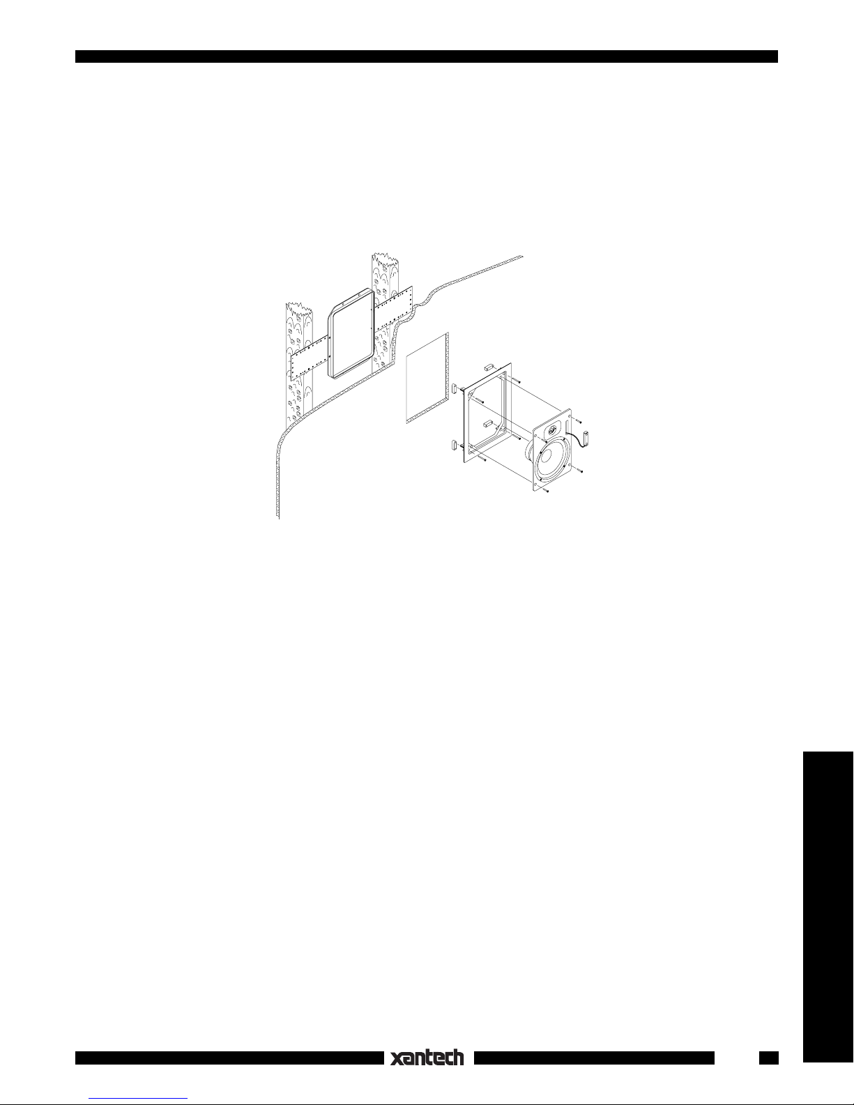
• Figure 3 illustrates an exploded, cutaway view of a
typical installation. (a) is the stud-mounted Roughin Kit, (b) is the plasterboard with the mounting hole
cut, (c) is the bezel with the four mounting “dogs”, (d)
is the baffle panel and speaker components and (e)
is the optional Dinky Link Infrared Receiver.
• Figure 4 shows the action of the rotating mounting
“dogs”.
Fig. 1c
Amplifier
Preampli
2
f
SPEAKERS
Page 3

Existing Construction
• Before cutting any holes in the wall, be certain that
the center of the opening is approximately centered
between the studs, that there are no supports or fire
baffles in the area of the hole and that there are no
electrical conduits, water or gas pipes in the way.
• Each bezel is packed with a die-cut piece of corrugated cardboard which is intended to be used as a
template. Locate it on the wall using a measuring
tape and a capenters level. Draw the outline of the
template on the wall using a pencil. Cut the opening
with knife, keyhole saw or saber saw.
Speaker Polarity (or phasing)
• The positive (+) or red binding post on the speaker
must be connected to the positive or red binding
post on the amplifier.
• The negaitve (-) or black connections must also
correspond.
• Left and right channel orientation must be correct.
Tweeter Level Adjustment
• Models S-64 and S-66 have a two-position tweeter
control located on the crossover board. This control
is designed to compensate for overall room acoustics or listener preference. The BRIGHT position
can be used for large, heavily draped or otherwise
“dead” rooms, while the FLAT position can be used
for small, hard surfaced rooms. On the S-64, a
jumper must be moved between the BRIGHT and
FLAT terminals, while a two-position slide switch is
provided on the S-66.
The tweeter control must be set before mounting the
•
speaker/baffle assembly to the bezel.
Dinky Link Installation
• The optional 480B-00 Dinky Link Infrared Receiver
can be mounted in a recess on the baffle panel.
• Remove the black foam block. Thread the cable
from the Dinky Link through the hole in the bottom
of the recess. Use the double sided tape to affix the
Dinky Link in the recess.
• In most installations, sufficient infrared energy will
pass through the perforated grille to reliably operate
the Dinky Link.
• If more range is required, and that additional range
can be achieved by removing the grille, a small lens
(supplied free upon request) can be added. The
lens requires a 3/8" hole in the grille. Determine the
hole location by sighting through an installed grille
with a flashlight.
SPEAKERS
Fig. 2a
Fig. 2b
Fig. 2c
3
Speakers & Volume Controls
Page 4

• The Dinky Link has two windows, one near the cable at the bottom and the other near the top. The lens
should be centered over the top window. Remove the grille from the bezel. Drill a 3/8" hole in the grille.
• A Xantech Unibit SD-200 Step Drill is recommended for drilling round holes in thin metal.
Fig. 2d
Fig. 3
(a)
(c)
(b)
(e)
(d)
4
Fig. 4
3-10-98
SPEAKERS
 Loading...