

Page 1
INSTALLATION INSTRUCTIONS
RMGATE
RACK MOUNT ADAPTER FOR THE GATEKEEP-IR
SOURCE
SAT 1
SAT 2
VCR 1
VCR 2
AUX
DVD 1
AUX 1
DVD 2
TUNER 1
TUNER 2
GATEKEEP-IR
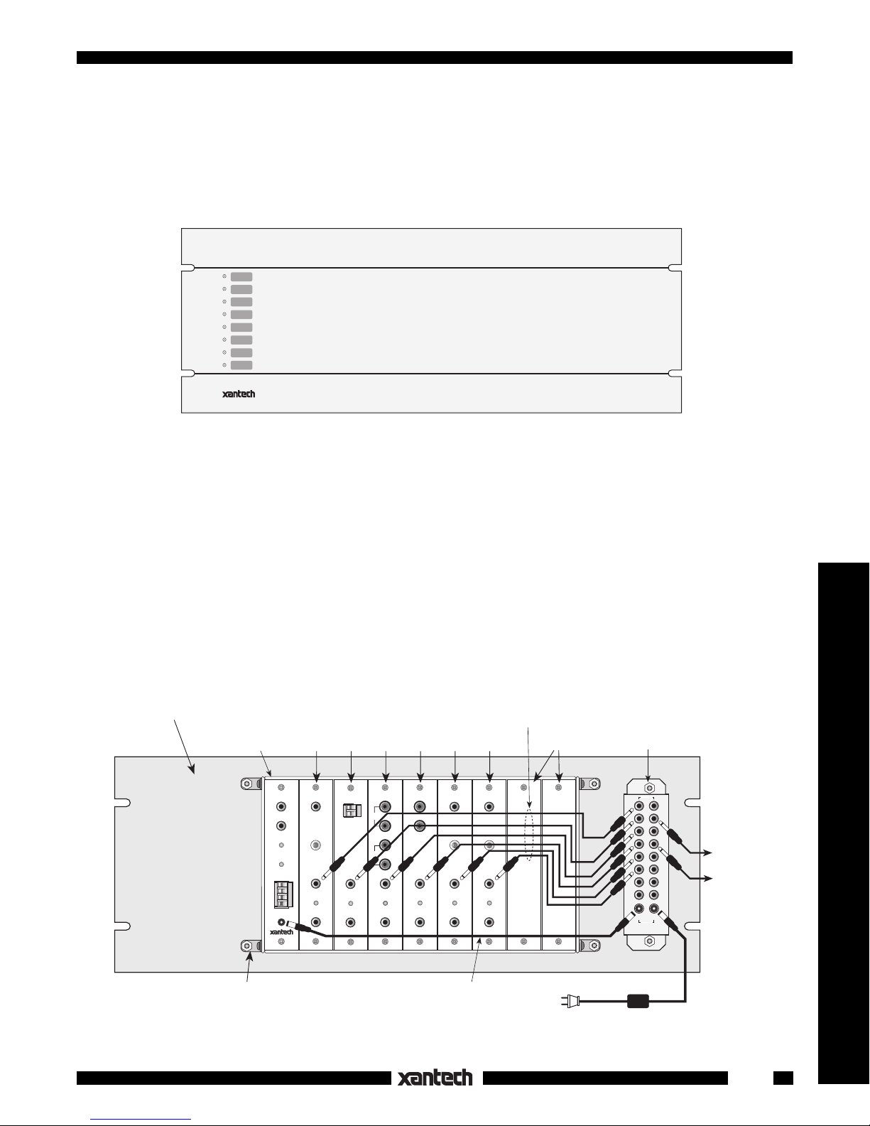
Fig. 1 The RMGATE, Front View
The RMGATE provides a convenient means for mounting the GATEKEEP-IR™ GMB9 assembly into a
standard 19 inch rack. It incorporates eight STATUS LED's that indicate a components ON/OFF condition.
The black anodized panel is a standard 7.00 inch increment height and is 3/16" thick. Install the panel as
follows:
1. Mount the GMB9 to the rear of the RMGATE. Refer to Fig. 2 below. Use the hardware that comes
with the GMB9 and the RMGATE.
2. Plug the 3.5-to-3.5mm Mono Mini Plug cables (supplied) between the STATUS jack of each gate
module to the corresponding STATUS GATE IN jack on the RMGATE as shown (Fig. 2). That is,
connect Gate 1 (slot #1) to GATE IN 1, Gate 2 (slot #2) to GATE IN 2, etc. Use the longer 18" cables
for the 4 gates to the left and the 12" cables for the remainder.
™
Remote Control Switchers
RMGATE RACK MOUNT ADAPTER
Mount the GMB9 Gatekeep-IR assembly to the 4 studs on the rear of the
RMGATE using hardware included with the GMB9 and the RMGATE.
(rear view)
GMB9
(not included)
GMM1A
CONFIRM
+12V
G
CI
IR IN
IR IN
IR OUT
POWER
12 VDC
Fig. 2 A GMB9 Gatekeep-IR™ Assembly Mounted to the Rear Surface of the RMGATE Rack Panel
Gate 1
(Slot #1)
GCM1
CURRENT
SENSOR
THRESHOLD
STATUS
ON
IR OUT
Gate 2
(Slot #2)
GEM1
+
–
CONTROL
IN
STATUS
ON
IR OUT
Gate 3
(Slot #3)
GAM1
IN
AUDIO
OUT
STATUS
ON
IR OUT
Gate 4
Gate 5
(Slot #4)
(Slot #5)
GVM1
L
VIDEO IN
R
L
R
TEMPERATURE
VIDEO OUT
STATUS
ON
IR OUT
2.1-to-2.1mm Power
Supply cable (included).
GTM1
SENSOR
THRESHOLD
STATUS
ON
IR OUT
3.5-to-3.5mm Mono
Mini Plug cables (8 included)
Gate 6
(Slot #6)
GLM1
LIGHT
SENSOR
THRESHOLD
STATUS
ON
IR OUT
To 120 V AC
(unswitched)
Unused
Slots
LED and STATUS
pass-thru' assembly
(included on RMGATE)
STATUS
GATEINGATE
OUT
11
22
33
44
55
66
77
88
OUT IN
POWER
782-00 Power Supply
(not included)
0 - 12Volt
STATUS pass-thru'
for indicators, for
control of other
equipment, etc.,
as needed.
1
Page 2

3. Plug the 2.1 to 2.1mm Power Supply cable (supplied), into the 12 VDC jack on the GMM1A and the
POWER OUT jack on the RMGATE, as shown.
4. Peel off the supplied Icon Labels (refer to Fig. 3) that correspond to the controlled equipment and place
them on the appropriate recessed locations opposite the LED's on the front panel.
5. Mount the completed assembly into a 19" rack using the rack panel cup washers and screws supplied.
6. When you have finished all other connections, plug a 782-00 Power Supply into the POWER IN jack
on the RMGATE (see Fig. 2).
LED's
SOURCE
SAT 1
SAT 2
VCR 1
VCR 2
AUX
DVD 1
AUX 1
DVD 2
TUNER 1
TUNER 2
AMP
AUX
AUX 1
CAM
CATV
CD
®
CD 1
CD 2
CD 3
DAT
DSS
DVD
Custom labels for RMGATE
PRE AMP
PROJ TAPE TV
DVD 2
LD RCVR
LD 1 SAT TAPE 2 TV 2
LD 2 SAT 1 TUNER TV 3
PHONO
SAT 2
Peel off the desired adhesive-backed Icon Labels and place
them on the recessed locations opposite the LED's that
correspond to the gate-controlled devices.
SRNDDVD 1
TAPE 1 TV 1
TUNER 1
TUNER 2
TV 4
VCR
VCR 1
VCR 2
ICON LABEL SHEET
(included)
RMGATE
(front view)
GATEKEEP-IR
Fig. 3 Applying the Icon Labels to the front of the RMGATE Rack Panel
2
2-22-01
RMGATE
Rev.B
 Loading...