

Page 1
INSTALLATION INSTRUCTIONS
RGC11
REMOTE GAIN CONTROL MODULE
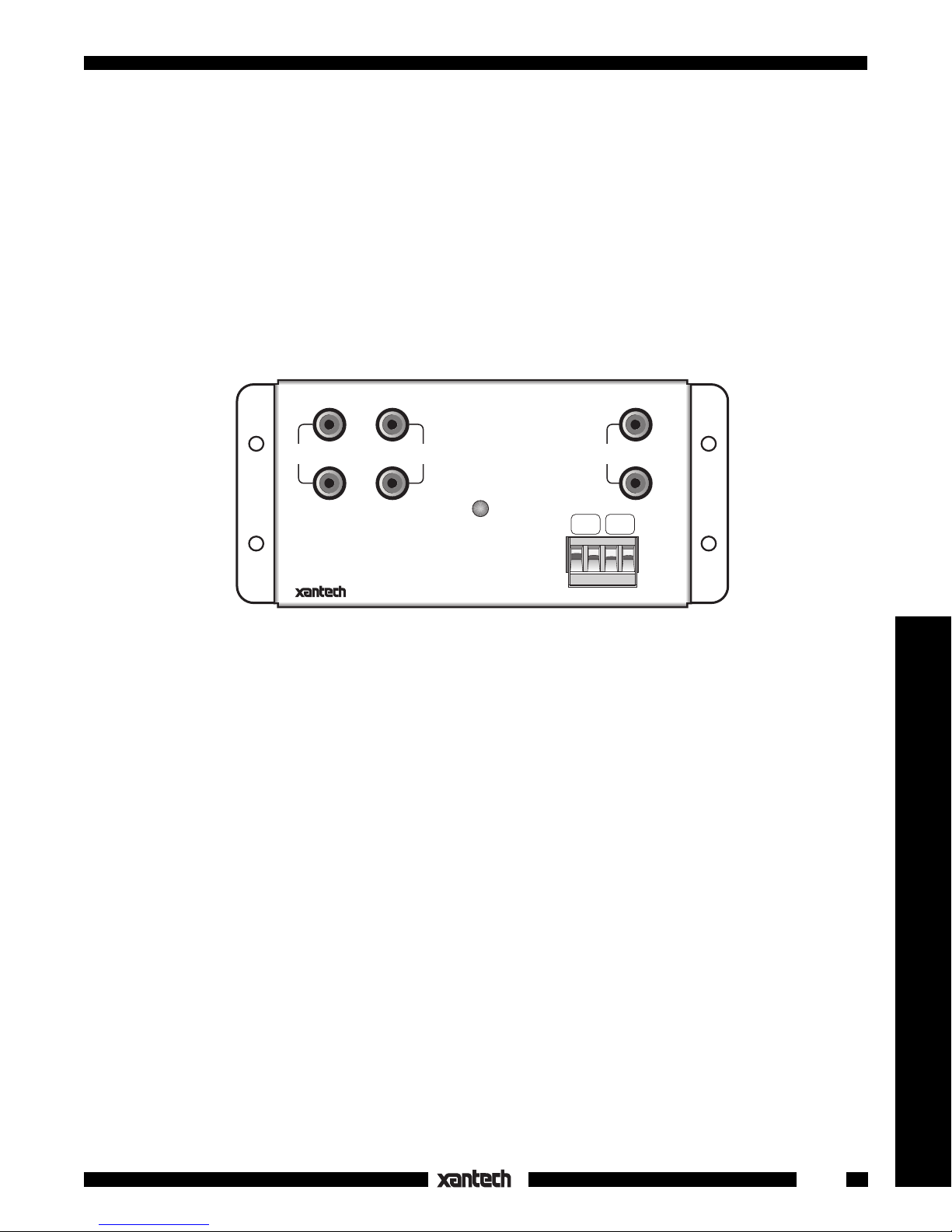
The RGC11, Fig. 1, is an IR Remote Controlled Line Level Gain Control Module. It permits line level gain
control of audio power amplifiers (instead of at speaker level), in multiroom installations, when highest
sound quality is desired. It may also be used in any application where IR remote control of gain is desired,
such as between the pre-out and main-in jacks of integrated amplifiers or receivers that were built without
remote control. Gain control is accomplished by way of infrared commands originating from a Xantech
RC68+ (or RC68) Programmer. The RC68+ commands are "taught" to learning devices and passed to the
RGC11 IR "IN" and "G" terminals via Xantech IR Receivers, Keypads and Connecting Blocks.
RGC11
INPUT
LEFT
RIGHT
LOOP
THROUGH
REMOTE GAIN
CONTROL MODULE
IR CONFIRM
IR
IN G
OUTPUT
15VAC
LEFT
RIGHT
V V
Fig. 1 The RGC11
FEATURES AND SPECIFICATIONS
• Requires RC68+ (or RC68) Programmer IR codes or the MIRV1 for operation.
• Responds to 16 IR commands: Volume Up/Down Ramping, 12 Fixed Levels, Mute ON and Mute OFF.
• IR Confirm LED lights steady when power is applied and blinks off with RGC11 IR commands only.
• Gold plated RCA type input & output jacks.
• Loop-through jacks (not buffered) for "daisy chaining" multiple RGC11’s.
2
• Selectable IR code groups. Internal E
PROM can be set to different group codes, allowing different IR
code combinations. This prevents mutual interaction in common IR systems when using more than one
RGC11, or if RGC11's are included with other Xantech products using RC68+ codes.
• Factory preset Group Code number: 30
• 4-terminal plug-in for IR input & power connections, IR IN (= IR Signal), G (= GND), V V= 15VAC. Accepts
wire sizes from 24 to 12 gauge.
• Power Requirements: 15VAC @ 85 mA. (15V AC power supply included).
• Gain: Unity @ Max. V.C.
• Input Impedance: 45 k Ohms
• Output Impedance: 220 Ohms
• Freq. Response: 5 Hz to 70 kHz ± 3 dB.
• THD: < 0.01% @ 2V out.
• S/N Ratio: > 103 dB "A" WTD re 2V out.
• Flanges, plus supplied screws, permits easy mounting to flat surfaces..
• Dimensions: 5-7/8" x 2-3/4" x 1-5/8"
1
Remote Control Switchers
Page 2
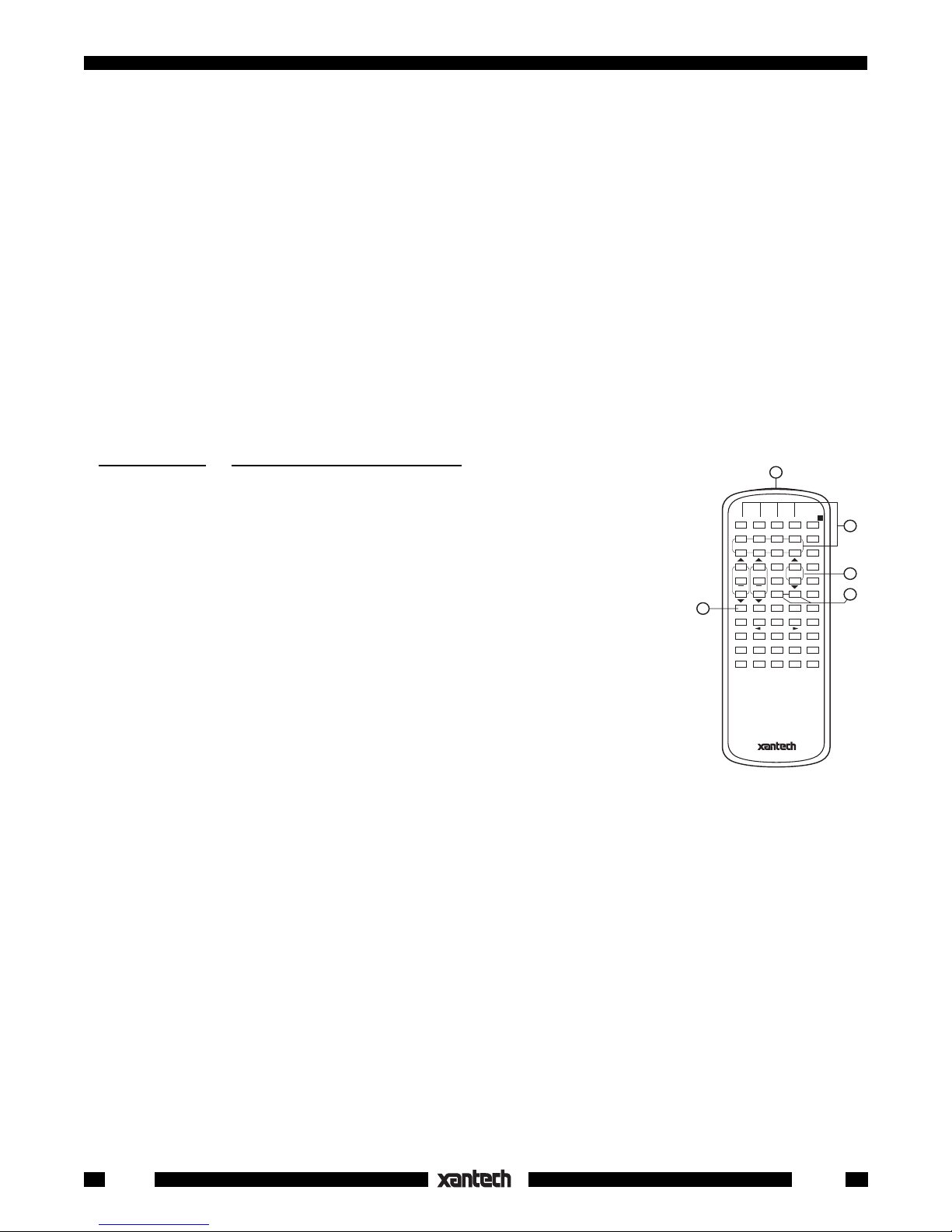
RC68+ or (RC68) PROGRAMMER / REMOTE CONTROL
The RC68+ Programmer (available separately) contains all the commands necessary to operate the
RGC11.
• You will need it to program universal learning devices such as the Xantech URC-1 learning remote, the
Xantech Smart Pads, the 590 Programmable Controller, the 710 Fone Link, etc., with commands that
operate the RGC11.
• NOTE: The RC68+ codes operate several other Xantech models as well, such as the RS41AV, CC12,
ZPR68, etc. Therefore, only the button descriptions that apply to the operation of the RGC11 are
listed below. All others should be ignored.
RC68+ BUTTONS THAT OPERATE THE RGC11
1. IR Emitter Lens.
2. Instant Volume Presets. These buttons allow random access or direct preset activation of any of 12
fixed preset levels on the RGC11. This is useful when setting up "audio scene" ambiance levels for
rooms or partial mute actions.
The relationship of the RC68+ buttons to the level attenuation below max. volume is as follows:
RC68+ Button RGC11 Level Attenuation - dB
A > 100 dB (OFF, MIN. VOL)
B57
C52
ADJ-OFF 47
142
237
332
427
523
618
Fig. 2 The RC68+
Programmer
5
1
A B C ADJ-OFF
80 48 10 90 01
1234
00 C0 50 D0 41
INPUT
5678
40 A0 30 B0 21
GLOBAL
20 E0 70 F0 61
BASS
TREBLE
60 88 18 98 09
08 A8 38 B8 29
28 E8 78 F8 69
E-FLAT LAST MAX-V TRIM
68 C8 58 D8 49
OFF C-BAL
E1 89 C9 A9 E9
71 19 59 39 79
F1 99 D9 B9 F9
Z-ADJ
MUTE
ON OFF
VOL
A
2
3
4
713
89
MAX VOLUME 0
3. VOLUME Up/Down. These buttons increase or decrease volume
RC68+ PROGRAMMER
in 2 dB steps between 0 dB and -80 dB. When buttons are held
down, the volume level will change continuously.
4. MUTE ON/OFF. Separate On / Off buttons give positive mute commands without knowing what the
status is. This is very helpful in a remote room when all adjustments are made “blind” without any visual
aids for status.
NOTE: Mute is released (turned off) with a VOLUME (3) or Preset Level button command, in addition
to MUTE OFF (4).
CAUTION: While the RC68+ can be used as a handheld remote control, it is highly recommended it not
be given to the final user for the following reasons:
• Since it includes adjustable code groups, the user may inadvertently alter the installer configurations.
• Since the user requires IR commands from other brands of equipment to control the total system, in addition to those of the RGC11, all commands should be consolidated into one learning device, for easy use.
5. Code Group Numbers. The RGC11 is capable of being set to different IR code groups.
NOTE: When shipped from the factory, the RGC11 is set to code group number 30.
Be sure to set the RC68+ to the same number!
It may be necessary to change the RGC11 to a different code group if it is used in a common IR bus
controlled system with other Xantech RGC11's, to avoid mutual interaction.
Refer to the RC68+ instructions for code group setting procedures.
2
RGC11
Page 3

INSTALLATION – COMMON IR BUS SYSTEMS
Fig. 3 illustrates a typical installation using three RGC11's along with other Xantech products in a 4-room
common IR bus
system. The principles shown should be used as a guide when planning your own specific
installations. It is configured as follows:
1. For simplicity, only three RGC11's are shown. A practical limit would be six RGC11's "daisy-chained"
using the "LOOP THROUG H" jacks as shown. This places a load of 7.5k Ohms (45k Ohms ÷ 6) on
the REC OUT jacks (or other driving source) of the main room receiver, etc. Use a Xantech AV-61
Distribution Amplifier when driving more than six. Each output of an AV-61 will drive as many as six
RGC11's.
NOTE: The REC OUT jacks on the receiver, amp, etc., are used since they provide a fixed output
independent of the main volume control.
common IR bus
2. A
connects the 780-80 "J" Box IR Receiver,the 480-00 "Dinky Link" IR Receiver, and
two Smart Pad3 keypads to each of the three RGC11's. In addition, it connects to a 789-44 Connecting
Block for control of the source components.
3. Since a common IR bus is used, each of the RGC11's and its connected MIRV1 (where used) must
use a different IR Code Group number, so that the volume level in each room can be adjusted
independent of the others. To make code group changes, refer to the RC68+ (or RC68) Programmer
Instructions.
NOTE:
When shipped from the factory, the RGC11 is set to code group number 30. If you use
group 30 or change to a different number, be sure to always set the RC68+ to the same number.
4. When a code group is chosen, "teach" volume commands from the RC68+ Programmer (see Fig. 2)
into learning remote controls (and the keypad), dedicated to each room. You may use the Xantech
URC-1 or URC-2 learning remote controllers for this purpose.
NOTE:
With a Common IR Bus system, you cannot carry the same remote control from roomto-room. You must use a dedicated remote for each room into which you have "taught" the
specific RC68+ code group that operates the specific RGC11 that controls the volume for that
room!
If you wish to carry remotes that have the same codes from room-to-room, use a Dedicated IR Bus
System as shown in Fig. 4.
5. A 490-30 "Micro Link" IR Receiver plugs into the 789-44 for local control of the source equipment (e.g.
equipment behind closed doors, etc.).
6. A "STATUS" system is included. This permits the power "ON/OFF" status of the A/V receiver or
amplifier system to be visible in each of the remote rooms. It also permits the power management
capability of the SmartPad3 to operate.
7. The "STATUS" indicator LEDs on the 780-80 "J" Box IR Receiver and the two SmartPad
's, are
3
powered by a 786-00 Power Supply plugged into a "SWITCHED" AC outlet on the A/V receiver or
amplifier system. When the switched outlet is "ON", +12 Volts from the 781C-00 passes through one
of the 4 bus-conductors (STATUS line) to the LED indicators.
NOTE: A resistor can be placed in series with the STATUS terminal at each IR receiver (IR receivers
only, if so equipped) for adjustment of the brightness of the Status LED. See the specific installation
instructions for the IR receiver for details.
NOTE:
their markings as follows:
When connecting system devices, be sure to carefully match up the terminals according to
IR IN or OUT (IR Signal), ST (Status), G (GND and V (+12 VDC).
Power Supply Considerations
Use one 15V AC power supply (included) for each RGC11. Add up the individual currents for each of the
other IR components in the system and choose the power supply accordingly. For instance, use the 781RG
for current demands up to 200 mA. For higher demands up to 1 A, use the 782-00 power supply.
Remote Control Switchers
RGC11
3
Page 4

MAIN ROOM, EQUIPMENT AREA, ETC.
RCA Type
Patch Cords
INPUT
RGC11
L
REC OUT
R
+ –
LEFT
LOOP
THROUGH
RIGHT
(for room 2)
786-00
"STATUS" power supply. Plug into a
AC Outlet on A/V Receiver (see text).
MAIN ROOM A/V RECEIVER,
AMPLIFIER, ETC.
(Back Panel)
SPEAKER TERMINALS
L R
+ - - +
+ –
Main Room
Speakers
RightLeft
RGC11
REMOTE GAIN
CONTROL MODULE
IR CONFIRM
IR
IN G
(+)
15V AC
Power Supply
(included)
OUTPUT
15VAC
V V
283M
Blink IR™
(Place on
FRONT
Panel IR
Sensor)
LEFT
RIGHT
120 V AC
(System
switched)
SWITCHED
782-00
Power Supply
120 V AC
(Unswitched)
RGC11
(for room 3)
LEFT
LOOP
INPUT
THROUGH
RIGHT
LEVEL
CH1 CH2
1V
.2V3V
LINE INPUTS
Xantech PA640 Input Panel
CH6 CH5
+ – – +
PROTECTION
+ –
BRIDGED
SPEAKERS
"Micro Link"
IR Receiver
(e.g.) cabinet mounted for
IR control in main room)
Connecting Block
(+)
(+)
RGC11
REMOTE GAIN
CONTROL MODULE
IR CONFIRM
BRIDGED
(+)
OUTPUT
IR
IN G
(+)
STEREO
15VAC
V V
PROTECTION
LEFT
RIGHT
LEVEL
1V
490-30
789-44
12VDC
+12 VDC
GND
STATUS
IR IN
RCVR
IR
15V AC
Power Supply
(included)
120 V AC
(System
switched)
CH3 CH4
.2V3V
LINE INPUTS
CH4 CH3
+ – – +
+ –
BRIDGED
SPEAKERS
CONNECTING BLOCK
789-44
EMITTERS
®
BRIDGED
STEREO
SOURCE COMPONENTS
RGC11
REMOTE GAIN
LEFT
CONTROL MODULE
LOOP
INPUT
THROUGH
RIGHT
IR CONFIRM
LEVEL
CH5 CH6
1V
.2V3V
LINE INPUTS
PA640 Speakers & AC Panel
CH2 CH1
+ – – +
PROTECTION
+ –
BRIDGED
SPEAKERS
CD Changer
Cassette DecK
283M
Blink IR™
Mouse Emitter
RGC11
(for room 4)
LEFT
OUTPUT
RIGHT
15VAC
IR
V V
IN G
(+)
(+)
BRIDGED
STEREO
283M
Blink IR™
15V AC
Power Supply
(included)
Power
Amplifiers
120 V AC
(System
switched)
4-Conductor
Common IR Bus Cables
L
R
+– +–
ST
G
IR IN
V
IR IN=IR Signal
780-80
"J" Box
IR Receiver
G=GND
ST=Status
V=+12V DC
ROOM 2
Fig. 3 An RGC11 System Using a Common IR Bus
4
L
+– +–
480-00
"Dinky Link"
IR Receiver
ST
G
VIR IN
Smart
Pad ™
R
L
R
+– +–
XANTECH
ST G VIR IN
3
Smart
Pad ™
3
S-62/64/66
Wall Speakers
ROOM 4ROOM 3
RGC11
Page 5

INSTALLATION – DEDICATED IR BUS SYSTEMS
Fig. 4 illustrates an installation where each remote room has a
Dedicated IR Bus
going to the RGC11 that
controls it. The IR bus is not connected in common as it is in Fig. 3. This eliminates the need for dedicated
remotes,
allowing you to carry the same remote(s) from room-to-room.
It is configured as follows:
1. Again, for simplicity, only three RGC11's are shown. A practical limit would be six RGC11's "daisychained" using the "LOOP THROUGH" jacks as shown. This places a load of 7.5k Ohms (45k Ohms
÷ 6) on the REC OUT jacks (or other driving source) of the main room receiver, etc. Use a Xantech
AV-61 Distribution Amplifier when driving more than six. Each output of an AV-61 will drive as many
as six RGC11's.
2. Each of the remote rooms has a Dedicated IR Bus that connects to its own RGC11 for independent
volume control. Note that only the S (IR signal) and G (gnd) leads of the 4-conductor bus connect to
the RGC11's IR IN & G terminals and the 793 Serial Combiner. The remaining leads, ST (status), G
(gnd) and V (+12VDC) go on to the 789-44 for STATUS and +12VDC power.
3. In order to control the common source components in a Dedicated IR Bus system, it is necessary to
use a 793-00 Serial Control Combiner, connected as shown in Figs. 4 & 5. The 793 provides diode
isolation between the dedicated IR signal lines but allows common operation of the source equipment
through the 789-44 Connecting Block, as shown.
Set the LOGIC POLARITY SELECTOR DIP switches on the 793 for "active high" operation - that is
- all even numbered switches to "ON" - all odd numbered switches to "OFF".
4. The input and output ports on the 793 are 3.5mm mono mini jacks. Use matching mini plug cables
with stripped ends when connecting. Polarity must be observed as shown in Fig. 4 & 5.
For systems using more than five RGC11's, you will need additional 793-00's. These can be easily
"daisy chained" as shown in Fig. 5.
5. Since a Dedicated IR Bus system is used, each of the RGC11's can operate with the same IR Code
Group number. In this case, the Code Group number, as received from the factory, should be used.
NOTE: When shipped from the factory, the RGC11 (and MIRV1's) are set to code group number
30. Be sure to set the RC68+ (or RC68) to the same number!
If a particular system requires a code group number change, refer to the RC68+ Programmer
Instructions for code group setting procedures.
6. The desired volume commands from the RC68+ Programmer (see Fig. 2) need to be "taught" into
learning remote controls and keypads used in the system. You may use the Xantech URC-1 or URC2 learning remote controllers for this purpose.
7. A 490-30 "Micro Link" IR Receiver plugs into the 789-44 for local control of the source equipment.
8. As in Fig. 3, a "STATUS" system is included. See items 6 and 7 under: Installation - Common IR Bus.
NOTE:
When connecting system devices, be sure to carefully match up the terminals according to their
markings as follows:
IR IN or OUT (IR Signal), ST (Status), G (GND) and V (+12V DC).
Daisy-Chaining 793-00 Serial Control Combiners for Control of Common Components
Fig. 5 illustrates how two 793-00 Serial Control Combiners are "Daisy-Chained" to accommodate additional
RGC11's in a dedicated IR Bus System. This process can be repeated as necessary to accommodate the
number of RGC11's needed in the system. Simply plug the "B" CONTROL OUTPUTS port of the added
793 into the "A" CONTROL OUTPUTS port on the preceding 793 with a 3.5-to-3.5mm mono-mini cable as
shown.
NOTE: Be sure that all ten LOGIC POLARITY SELECTOR DIP switches on each 793 are set correctly. In
this case, set them for "active high" operation - that is - all even numbered switches to "ON" - all odd
numbered switches to "OFF".
Remote Control Switchers
RGC11
5
Page 6

MAIN ROOM, EQUIPMENT AREA, ETC.
INPUT
RGC11
L
R
REC OUT
+ –
RCA Type
Patch Cords
LEFT
THROUGH
RIGHT
(for room 2)
786-00
"STATUS" power supply. Plug into a SWITCHED
AC Outlet on A/V Receiver (see text).
MAIN ROOM A/V RECEIVER,
AMPLIFIER, ETC.
(Back Panel)
SPEAKER TERMINALS
L R
+ - - +
Main Room
Speakers
RightLeft
RGC11
REMOTE GAIN
CONTROL MODULE
LOOP
IR CONFIRM
IR
IN G
G
S
S
15V AC
Power Supply
(included)
OUTPUT
G
+ –
15VAC
V V
283M
Blink IR™
(Place on
FRONT
Panel IR
Sensor)
LEFT
RIGHT
120 V AC
(System
switched)
782-00
Power Supply
To 120 V AC
(unswitched)
Serial Combiner
GS
G
SGS
RGC11
(for room 3)
LEFT
LOOP
INPUT
THROUGH
RIGHT
IR CONFIRM
LEVEL
CH1 CH2
1V
.2V3V
LINE INPUTS
Xantech PA640 Input Panel
CH6 CH5
+ – – +
PROTECTION
+ –
BRIDGED
SPEAKERS
793-00
INPUTS
CONTROL
793-10
SERIAL CONTROL
1 2 3 4 5
A B
OUTPUTS
CONTROL
RGC11
REMOTE GAIN
CONTROL MODULE
S
G
BRIDGED
STEREO
(i.e. cabinet mounted
COMBINER
SELECTOR
1 2 3 4 5 6 7 8 910
ON
LOGIC POLARITY
LEFT
OUTPUT
RIGHT
15VAC
IR
V V
IN G
G
S
LEVEL
1V
.2V3V
PROTECTION
490-30
"Micro Link"
IR Receiver
for IR control
in main room)
Connecting Block
(+)
G
S
15V AC
Power Supply
(included)
120 V AC
(System
switched)
BRIDGED
CH3 CH4
LINE INPUTS
CH4 CH3
+ – – +
+ –
BRIDGED
SPEAKERS
789-44
12VDC
+12 VDC
GND
STATUS
IR IN
®
RCVR
IR
INPUT
STEREO
PROTECTION
CONNECTING BLOCK
789-44
EMITTERS
RGC11
REMOTE GAIN
LEFT
CONTROL MODULE
LOOP
THROUGH
RIGHT
IR CONFIRM
LEVEL
CH5 CH6
1V
.2V3V
LINE INPUTS
PA640 Speakers & AC Panel
CH2 CH1
+ – – +
+ –
BRIDGED
SPEAKERS
SOURCE
COMPONENTS
CD Changer
283M
Blink IR™
Cassette DecK
283M
Blink IR™
Mouse Emitter
RGC11
(for room 4)
LEFT
15V AC
Power Supply
RIGHT
15VAC
V V
STEREO
Amplifiers
IN G
GSGS
OUTPUT
IR
BRIDGED
(included)
120 V AC
(System
switched)
Power
4-Conductor
Dedicated IR
Bus Cable
L
R
+– +–
ST G
V
780-80
"J" Box
IR Receiver
IR IN
IR IN=IR Signal
G=GND
ST=Status
V=+12V DC
ROOM 2
Fig. 4 A Dedicated IR Bus RGC11 System
6
L
+– +–
480-00
"Dinky Link"
IR Receiver
ST
G
VIR IN
Smart
Pad ™
4-Conductor
Dedicated IR Bus Cables
R
L
R
+– +–
XANTECH
ST G VIR IN
3
Smart
Pad ™
3
S-62/64/66
Wall Speakers
ROOM 4ROOM 3
RGC11
Page 7

793-00
Serial Combiner
793-00
Serial Combiner
CONTROLLED
COMPONENTS
CD Changer
Cassette Deck
283M
Blink IR™
Mouse
Emitter
283M
Blink IR™
To
additional
Emitters
if needed
To IR IN
and G on
each RGC11
INPUTS
CONTROL
793-10
SERIAL CONTROL
COMBINER
1 2 3 4 5
SELECTOR
ON
LOGIC POLARITY
A B
OUTPUTS
CONTROL
"Daisy-Chain"
connection. Use
3.5/3.5mm MiniPlug cable,
Pt. # 6017400
1 2 3 4 5 6 7 8 910
To IR IN
and G on
each RGC11
INPUTS
CONTROL
793-10
SERIAL CONTROL
COMBINER
1 2 3 4 5
SELECTOR
ON
LOGIC POLARITY
A B
OUTPUTS
CONTROL
Use Mini-Plug-
to-Stripped
end cables,
Pt. # 6015900
1 2 3 4 5 6 7 8 910
–
+
White
Striped
Side (+)
789-44
Connecting Block
12VDC
+12 VDC
GND
STATUS
IR IN
RCVR
CONNECTING BLOCK
®
IR
789-44
EMITTERS
Fig. 5 Daisy-Chaining 793-00's in Multiple RGC11 Dedicated IR Bus Systems
ADDING REMOTE VOLUME TO A NON-REMOTE COMPONENT
The RGC11 is an ideal product to add IR remote volume control to a stereo receiver or integrated amplifier
that was built without it. Fig. 6 illustrates such a system. It is configured as follows:
1. The RGC11 is connected between the PRE OUT and MAIN IN jacks on the back of the unit as shown.
2. In actual use, you would set the unit's front panel volume control to about 50% rotation and use the
RGC11 for all subsequent volume adjustments.
3. A 789-44 Connecting Block is used so that other product can be controlled as well as the RGC11.
4. The power supply for the RGC11 is plugged into a switched AC outlet on the unit so that it will power
ON and OFF with the main power switch.
Remote Control Switchers
STEREO RECEIVER, INTEGRATED AMPLIFIER, ETC.
WITHOUT
IR REMOTE CONTROL
(Back Panel)
MAIN
IN
LOOP
THROUGH
L
SPEAKER TERMINALS
R
RGC11
REMOTE GAIN
CONTROL MODULE
IR CONFIRM
L R
+ - - +
IN G
(+)
IR
INPUT
L
PRE
OUT
R
RCA Type
Patch Cords
LEFT
RIGHT
Fig. 6 Adding Remote Volume Control to a Non-Remote Component
1-11-01
Rev.B
RGC11
OUTPUT
15VAC
V V
LEFT
RIGHT
15V AC
Power
Supply
(included)
SWITCHED
AC OUTLET
781RG
Power Supply
To 120 V AC
(unswitched)
490-30
"Micro Link"
IR Receiver
(e.g.) cabinet mounted for
IR control in main room)
789-44
Connecting Block
12VDC
CONNECTING BLOCK
+12 VDC
789-44
EMITTERS
GND
STATUS
IR IN
®
RCVR
IR
SOURCE COMPONENTS
CD Changer
283M
Blink IR™
Cassette DecK
283M
Blink IR™
Mouse Emitter
7
 Loading...