

Page 1
INSTALLATION INSTRUCTIONS
MODEL MRC44KP
MRC44 KEYPAD
Page 2

Page 2 Model MRC44KP
© 2001 Xantech Corporation
Page 3

Model MRC44KP Page 3
© 2001 Xantech Corporation
TABLE OF CONTENTS
Section Title
MRC44 Keypad Feature Descriptions...........................................................4
Installation
MRC44 Keypad Physical Location and Mounting ................................. 10
MRC44 Keypad Removal.....................................................................14
Connections at the Zone Location........................................................ 16
For additional information on installation of the MRC44 System,
refer to the MRC44 Installation Instructions, part no. 08901160.
Page 4
Page 4 Model MRC44KP
© 2001 Xantech Corporation
MRC44 KEYPAD FEATURE DESCRIPTIONS
POWER
CH
CH
STATUS
SELECT
PLAY
STOP
PAUSE
FF
REW
VOL
VOL
MUTE
5 3
6
7 8
10
11
12
16
13
14
15
9
4
1
2
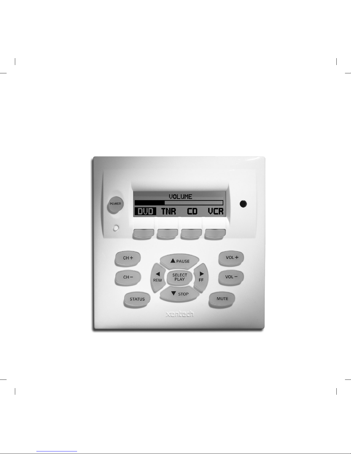
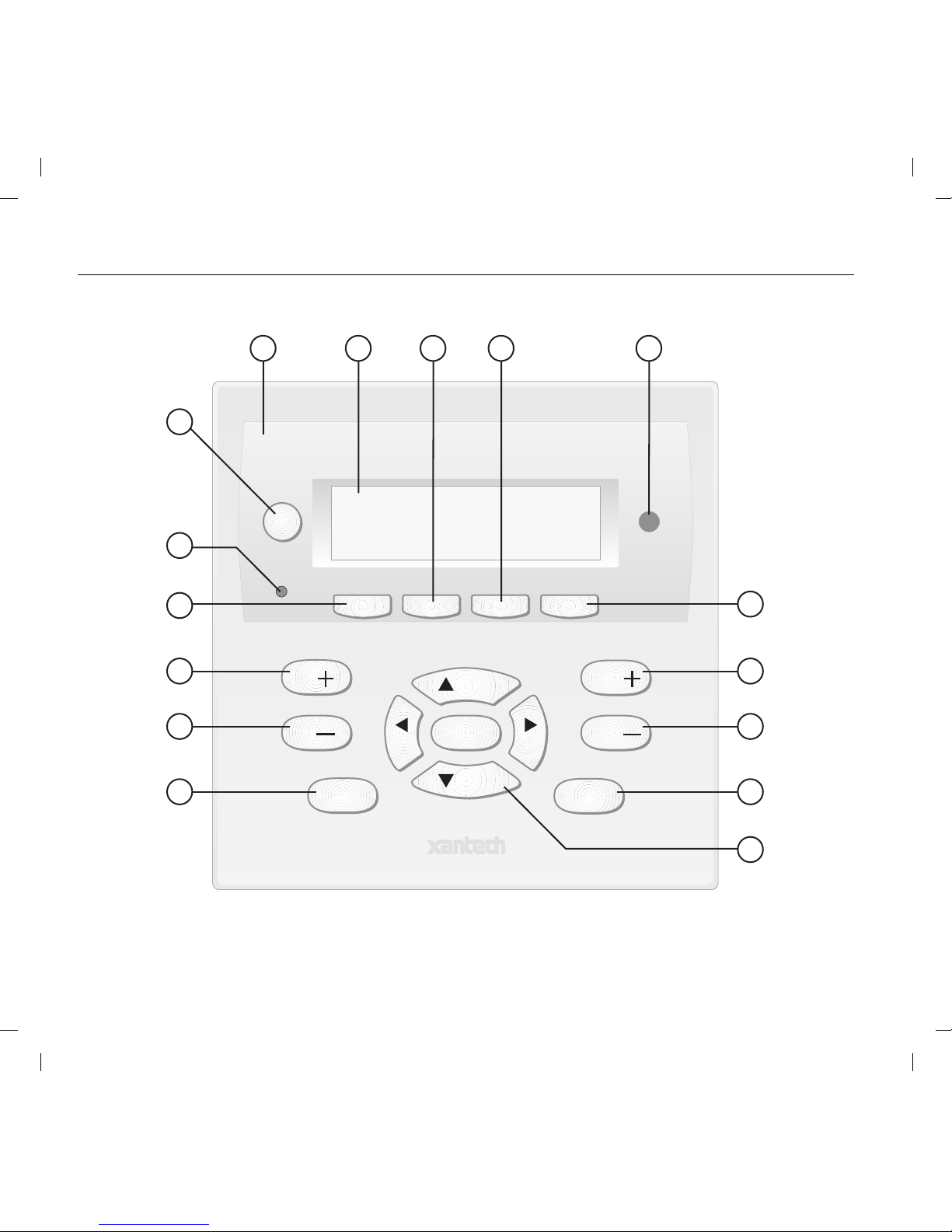
Figure 1 – The Model MRC44 Keypad
Front Panel Features and Functions
Page 5

Model MRC44KP Page 5
© 2001 Xantech Corporation
1. MRC44 Keypad.
2. Power. Turns the zone ON and OFF. Can be programmed with IR
codes or sequences.
3. IR Sensor. Receives IR from hand-held remotes to control both source
components and the MRC44 system. A Programmable Learning Remote
such as the Xantech URC2 is recommended for integrating the IR
commands of the MRC44 and source components into a single
controller. Compatible with most brands of remote controls, though some
may not be programmable and will therefore only control the source
components.
4. Status Indicator LED. Will indicate zone/system status and will flash as
IR is received at the IR Sensor. These indicators, one for each Keypad,
provide the following Information:
a) Off=Zone OFF
b) Steady Green=Zone ON
c) Flash Green=Zone MUTE
d) Flash Red=IR Sensor INPUT or Keypad OUTPUT
e) Flash Amber=System BUSY
5. LCD Display. When the zone power is ON, the LCD will indicate the
selected source, zone and system status, zone volume level and other
system conditions. The display is automatically backlit when any button
is pressed.
Page 6

Page 6 Model MRC44KP
© 2001 Xantech Corporation
6. Source 1 Selector. Selects source input 1, reverses source icon on LCD
Display when source is selected and sends IR commands programmed
to this button (if any) to the source 1 and common emitter outputs. Also
used in Dynamic Monitor Lockout and Dynamic Zone Link Modes.
7. Source 2 Selector. Selects source input 2, reverses source icon on LCD
Display when source is selected and sends IR commands programmed
to this button (if any) to the source 2 and common emitter outputs. Also
used in Dynamic Monitor Lockout and Dynamic Zone Link Modes.
8. Source 3 Selector. Selects source input 3, reverses source icon on LCD
Display when source is selected and sends IR commands programmed
to this button (if any) to the source 3 and common emitter outputs. Also
used in Dynamic Monitor Lockout and Dynamic Zone Link Modes.
9. Source 4 Selector. Selects source input 4, reverses source icon on LCD
Display when source is selected and sends IR commands programmed
to this button (if any) to the source 4 and common emitter outputs. Also
used in Dynamic Monitor Lockout and Dynamic Zone Link Modes.
10. Vol
+. Increases zone volume and moves the Volume Bar on the LCD
Display to indicate volume level (non-programmable).
Page 7

Model MRC44KP Page 7
© 2001 Xantech Corporation
11. Vol -. Decreases zone volume and moves the Volume Bar on the LCD
Display to indicate volume level (non-programmable).
12. Mute. Mutes zone speaker output. Sends IR commands programmed to
this button (if any) to the selected source and common emitter outputs.
13. CH
+. Sends IR commands programmed to this button to the selected
source and common emitter outputs.
14. CH
-. Sends IR commands programmed to this button to the selected
source and common emitter outputs.
15. Status. Displays zone and system status (zone/source activity, linked
zones, audio setup, etc – non-programmable).
16. Select/Play, Stop, Pause, Rew, FF. Each send IR commands
programmed to these buttons to the selected source and common
emitter outputs.
Page 8
Page 8 Model MRC44KP
© 2001 Xantech Corporation
2418 17
22
23
20
19
21
24
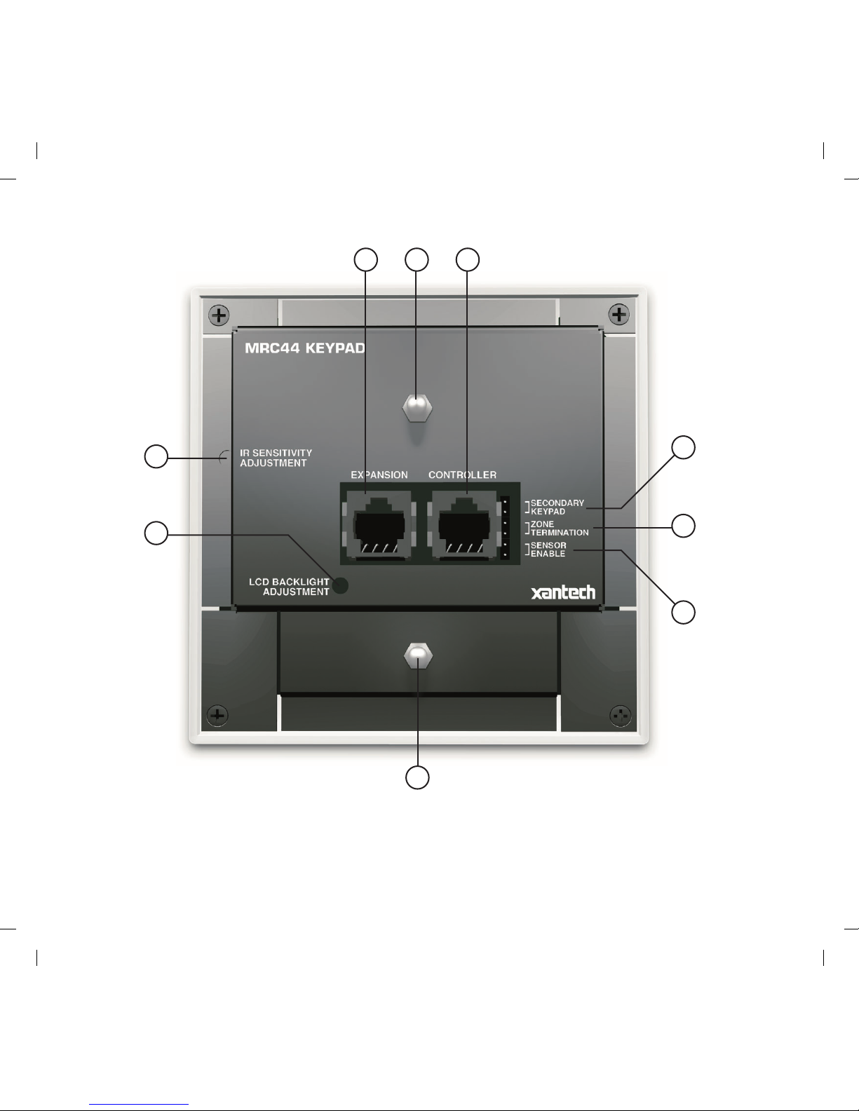
Figure 2 – The Model MRC44 Keypad
Rear Panel Features and Functions
Page 9

Model MRC44KP Page 9
© 2001 Xantech Corporation
17. Controller Terminal. RJ45 Jack. Connects Keypad to zone keypad
input on MRC44 Controller via CAT5 cable.
18. Expansion Terminal. RJ45 Jack. Allows a second Keypad or external
IR receiver for each zone.
19. Secondary Keypad. Jumper. Used to configure as secondary keypad in
zone.
20. Zone Termination. Jumper. Do not remove jumper if there is only one
keypad in a zone. If there are two keypads in a zone, remove only from
the first keypad.
21. Enable Sensor. Jumper. Enables IR sensor on Keypad. Remove when
using an external IR receiver.
22. IR Sensitivity Adjustment. Carefully adjust for background light level to
prevent false triggering of the IR circuits. Slowly turn counter-clockwise
to reduce sensitivity.
23. LCD Backlight Adjustment. Adjusts brightness of LCD backlight. This
adjustment does not affect the backlight level for the buttons. Slowly turn
counter-clockwise to reduce brightness.
24. Snap-in Pins. These pins snap into the MRC44 Keypad wall bracket for
mounting.
Page 10
Page 10 Model MRC44KP
© 2001 Xantech Corporation
MRC44 KEYPAD PHYSICAL LOCATION AND MOUNTING
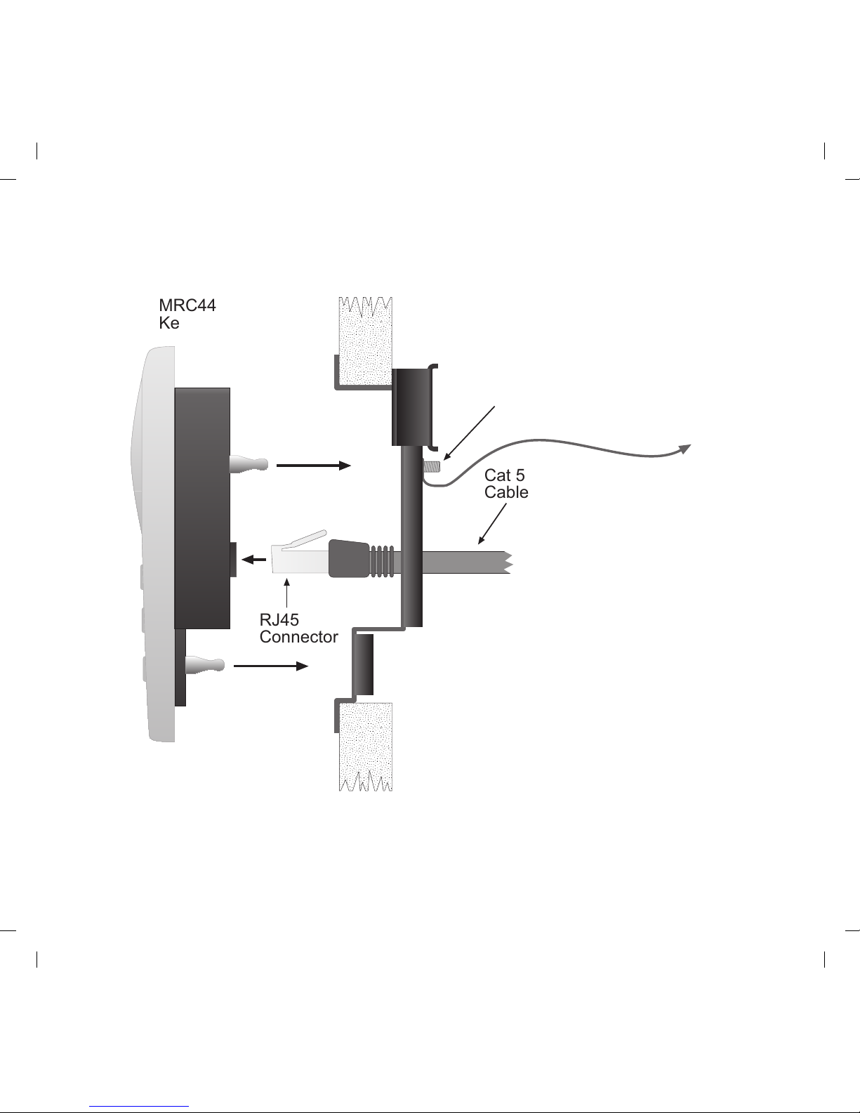
RJ45
Connector
Cat 5
Cable
MRC44
Keypad
Ground
Lug
To Earth Ground
Figure 3 - Mounting and Installing the MRC44 Keypad
Page 11
Model MRC44KP Page 11
© 2001 Xantech Corporation
Keypad mounting for the MRC44 Keypad does not require a junction box.
The MRC44 keypad can be mounted on drywall, lath & plaster, button board
or other surfaces covering a hollow wall. Follow these simple procedures to
install the provided MRC44 mounting bracket and keypad:
1. Cutting the hole
a. Mark the desired mounting location for the center of the keypad.
b. Using a level, make proper horizontal and vertical marks on surface
to be cut, to properly orient template.
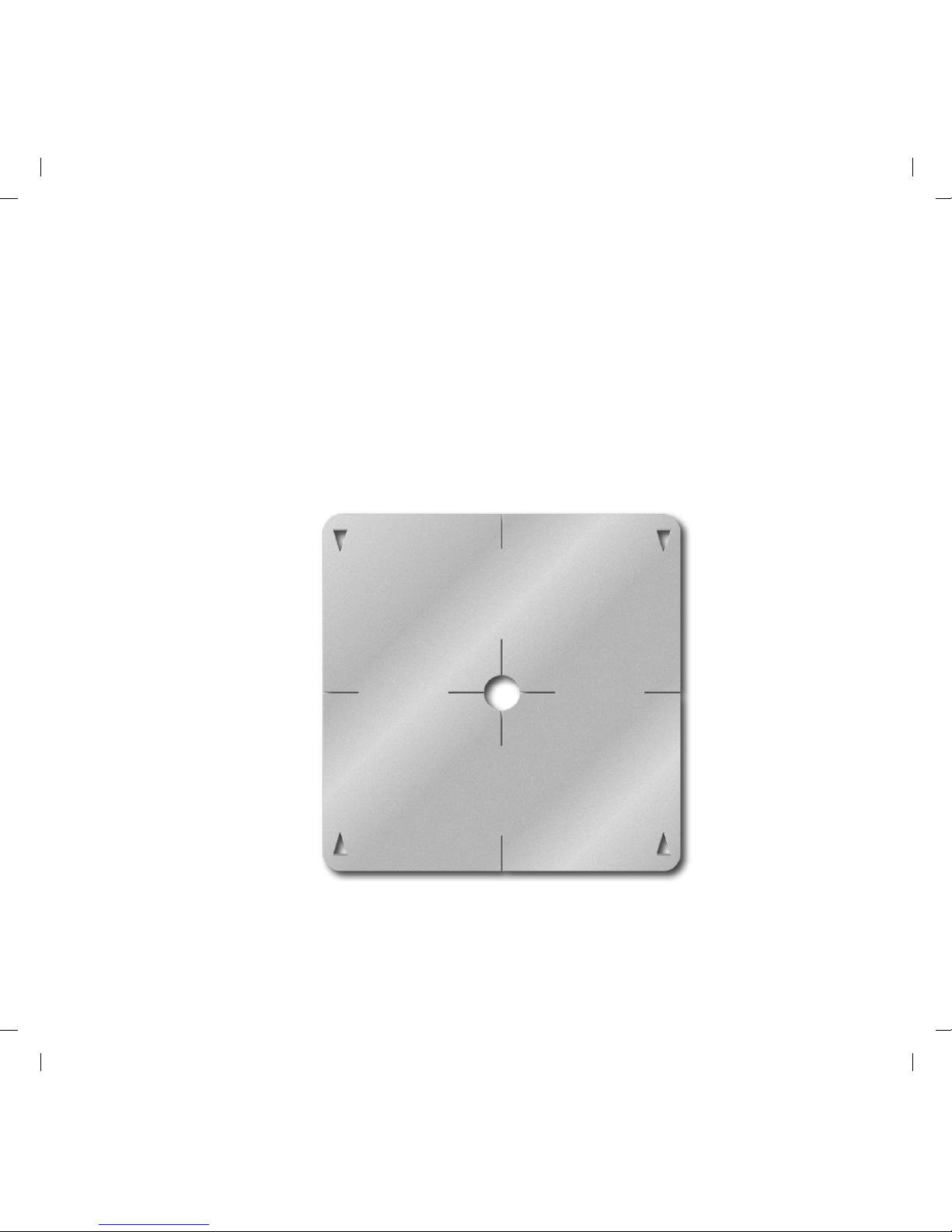
Figure 4 – MRC44 Keypad mounting template
Page 12

Page 12 Model MRC44KP
© 2001 Xantech Corporation
c. Locate the provided template so that the mark is in the center of the
hole, which is in the center of the template.
d. Rotate the template around the center until the template is level.
e. Press or hammer the template in place so that the holding tabs
pierce the wall and hold the template in place.
f. Mark or scribe the outline of the template on the wall.
g. Remove the template and cut a clean hole through the wall along the
outline of the template, being sure that your cut is on the outline. Any
cut outside of the outline by more than ¼” may not be covered by the
keypad.
1
2
Figure 5 – Installing the MRC44 Keypad mounting bracket in the wall
Page 13

Model MRC44KP Page 13
© 2001 Xantech Corporation
2. Installing the Mounting Bracket
a. Attach the ground wire to the ground lug to the rear of the back-bar
with the provided green screw, before beginning the bracket
installation process.
NOTE: A ground wire connected to Earth ground is required to
protect against static discharge.
b. Run the supplied screws through the top (marked on the front of the
bracket) of the mounting bracket into the back-bar as shown in
Figure 5.
c. Pull the CAT5 cable through the hole in the wall.
d. Pull the CAT5 cable through the hole in the mounting bracket.
e. Slide the left or right side of the back-bar into the wall.
f. Center the mounting bracket in the wall and tighten the screws until
the bracket is firmly held in the wall. Over tightening will distort the
bracket and prevent the Keypad from snapping tight against the wall.
Under tightening will cause the Keypad to be loose against the wall.
g. If there is not enough room to slide the keypad in as described
above, you can hold the back-bar in place as you run the screws
through the mounting plate and into the back-bar. TIE A LONG
STRING TO THE BACK-BAR so that you can easily retrieve it in
case you drop the back-bar into the wall!
3. With the Controller/Amplifier turned off, connect the CAT5 cable to the
appropriate RJ45 connector, using Figure 7 as a guide for CAT5
termination.
4. Add or remove jumpers on the rear of the MRC44 keypad-according to
Table 1 (Keypad connections).
Page 14

Page 14 Model MRC44KP
© 2001 Xantech Corporation
5. Firmly snap the MRC44 Keypad into the bracket that you have just
installed (see Figure 3).
6. Confirm all Keypad operations.
MRC44 KEYPAD REMOVAL
POWER
CH
CH
STATUS
SELECT
PLAY
STOP
PAUSE
FF
REW
VOL
VOL
MUTE
1
2
Figure 6 – Removing the MRC44 Keypad from the wall
Page 15
Model MRC44KP Page 15
© 2001 Xantech Corporation
1. Insert the MRC44 keypad removal tool into the slot at the bottom of the
keypad, as shown in Figure 6, being sure that the tool is inserted so that
the “insert to here” line slides under the Keypad. This will reduce the risk
of damage to the Keypad or the wall.
2. Twist the removal tool in either direction until the bottom of the Keypad
pulls away from the wall, then carefully grip the edges of the Keypad with
your fingers and pull it off the wall.
NOTE: Since the Keypad snaps into the mounting bracket and there are
a large variety of wall textures, the Keypad may POP OUT or require
some additional effort to pull it off the wall, depending on your particular
installation.
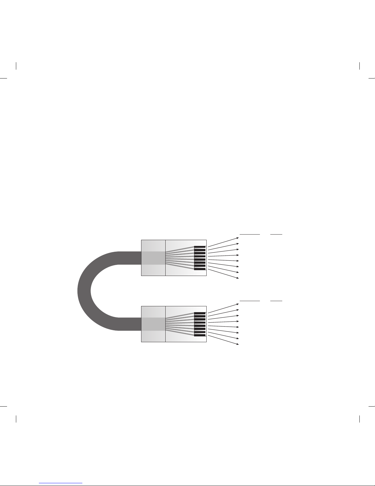
Wire Color Signal
white/orange Tx+
orange Txwhite/green 12V RET
blue IR RET
white/blue IR
green +12V
white/brown Rx+
brown Rx-
Cat 5
Cable
RJ45 Connector at
Controller/Amplifier
RJ45 Connector
at Keypad
Wire Color Signal
white/orange Rx+
orange Rxwhite/green 12V RET
blue IR RET
white/blue IR
green +12V
white/brown Tx+
brown Tx-
Figure 7 - CAT5 Pin Assignments (per EIA/TIA 568B)
Page 16

Page 16 Model MRC44KP
© 2001 Xantech Corporation
MRC44 Keypad Cable Connections at the MRC44 Controller/Amplifier
1. See Figure 7 for termination of the CAT5 cables to the RJ45 connectors.
2. Connect the zone keypad to the appropriate zone Keypad connector on
the rear of the MRC44 Controller/Amplifier.
CONNECTIONS AT THE ZONE LOCATION
Single Keypad Connections
1. Refer to Figure 7 for proper termination at the zone-end of the CAT5
cable.
2. Connect the CAT5 cable from the MRC44 Controller/Amplifier into the
RJ45 jack marked “Controller” on the rear of the MRC44 keypad.
3. Depending on the number of MRC44 keypads and IR receivers used in a
zone the jumper pins on the MRC44 keypad are to be connected as
shown in Table 1.
Multiple Keypad Connections
1. For a second keypad in the same zone, terminate the CAT5 cable with
the same configuration as shown in Figure 7.
2. Connect the CAT5 coming from the MRC44 Controller to the
“CONTROLLER” jack on the Primary Keypad. Plug a CAT5 cable into
the “EXPANSION” jack on the Primary Keypad and connect it to the
“CONTROLLER” jack on the Secondary Keypad. Set the jumpers
according to the above Table 1.
3. When adding an IR receiver in the zone, set the jumpers according to the
above table and connect the cables as shown in Figure 8.
Page 17
Model MRC44KP Page 17
© 2001 Xantech Corporation
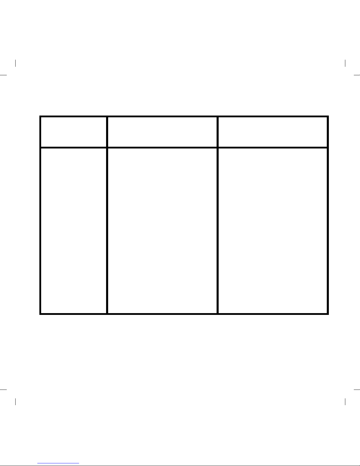
Primary Keypad Secondary Keypad
Application
Secondary
Keypad
Zone
Termination
Sensor
Enable
Secondary
Keypad
Zone
Termination
Sensor
Enable
One keypad in
Zone with IR
Sensor enabled
OFF ON ON
Two Keypads in
Zone with IR
Sensors enabled
OFF OFF ON ON ON ON
One Keypad and
one separate IR
Receiver in Zone
OFF ON OFF
Two Keypads and
two separate IR
Receivers in Zone
(Sub-Zone)
OFF OFF OFF ON ON OFF
Table 1 – MRC44 Keypad Jumper Configurations
Page 18
Page 18 Model MRC44KP
© 2001 Xantech Corporation
Extended Runs and Secondary Keypad In Zone
FOUR ZONE - FOUR SOURCE AUDIO/VIDEO CONTROLLER/AMPLIFIER
MRC44
1234
POWER
POWER
CH
CH
STATUS
SELECT
PLAY
STOP
PAUSE
FF
REW
VOL
VOL
MUTE
POWER
CH
CH
STATUS
SELECT
PLAY
STOP
PAUSE
FF
REW
VOL
VOL
MUTE
1000 feet max
IR Receiver
PWR
VGS
IR RCVR
IR Receiver
To 120 V AC
(unswitched)
782-00
Power Supply
MRC44
Connecting Block
FOUR ZONE - FOUR SOURCE AUDIO/VIDEO CONTROLLER/AMPLIFIER
MRC44
1234
POWER
POWER
CH
CH
STATUS
SELECT
PLAY
STOP
PAUSE
FF
REW
VOL
VOL
MUTE
POWER
CH
CH
STATUS
SELECT
PLAY
STOP
PAUSE
FF
REW
VOL
VOL
MUTE
200 feet max
MRC44
Connecting
Block
IR Receiver
PWR
VGS
IR RCVR
IR Receiver
FOUR ZONE - FOUR SOURCE AUDIO/VIDEO CONTROLLER/AMPLIFIER
MRC44
1234
POWER
POWER
CH
CH
STATUS
SELECT
PLAY
STOP
PAUSE
FF
REW
VOL
VOL
MUTE
400 feet max
IR Receiver
FOUR ZONE - FOUR SOURCE AUDIO/VIDEO CONTROLLER/AMPLIFIER
MRC44
1234
POWER
POWER
CH
CH
STATUS
SELECT
PLAY
STOP
PAUSE
FF
REW
VOL
VOL
MUTE
POWER
CH
CH
STATUS
SELECT
PLAY
STOP
PAUSE
FF
REW
VOL
VOL
MUTE
200 feet max
IR Receiver
A
B
C
D
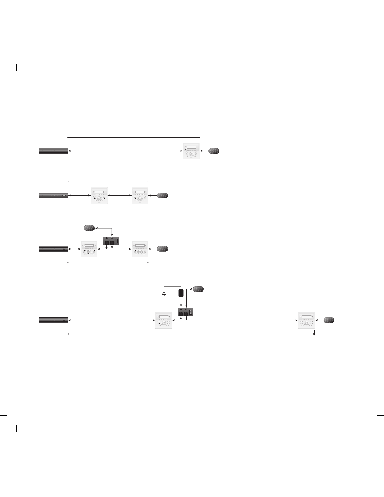
Figure 8 – MRC44 Keypad CAT5 Cable Lengths
Page 19

Model MRC44KP Page 19
© 2001 Xantech Corporation
The maximum cable length for CAT5 connections to a single keypad is 400
feet (see Figure 8A). For two keypads in a zone, the distance to the last
keypad is 200 feet (see Figure 8B).
PWR
VGS
IR RCVR
Figure 9 – MRCCB1 MRC44 Connecting Block
If both keypads in the zone are using an external IR receiver, the MRC44
Connecting Block (see Figure 9) is used to expand the connections on
the back of the primary keypad as shown in Figure 8C.
If your installation requires cabling beyond these limits you can use the
MRC44 Connecting Block to power the keypads from a separate run of
+12VDC as shown in Figure 8D. The +12VDC can also be generated in
the zone from a model 782 power supply or from a source at the
Controller/Amplifier location (run an 18 gauge speaker wire to the
MRC44 Connecting Block to minimize line loss. This method will extend
the distance to the last keypad in the zone to a maximum of 1000 feet.
The Maximum cable run to the external IR receiver in each of the above
cases is 250 feet from the keypad.
Page 20

XANTECH CORPORATION
12950 Bradley Avenue, Sylmar CA 91342-3829
phone 818.362.0353 • fax 818.362.9506
www.xantech.com
Part No. 08901175 Rev A 05-17-2002
 Loading...