

Page 1
INSTALLATION INSTRUCTIONS
MODEL MRC44
FOUR ZONE – FOUR SOURCE
AUDIO/VIDEO CONTROLLER/AMPLIFIER SYSTEM
Page 2
Page: 2 Model MRC44
SAFETY INSTRUCTIONS - READ BEFORE OPERATING EQUIPMENT
CAUTION: TO REDUCE THE RISK OF ELECTRIC SHOCK,
DO NOT REMOVE COVER (OR BACK)
NO USER-SERVICEABLE PARTS INSIDE
REFER SERVICING TO QUALIFIED SERVICE PERSONNEL
The lightning flash with arrowhead symbol, within an equilateral triangle,
is intended to alert the user to the presence of un-insulated “dangerous
voltage” within the product’s enclosure that may be of sufficient magnitude
to constitute a risk of electric shock to persons.
The exclamation point within an equilateral triangle is intended to alert the
user to the presence of important operating and maintenance (servicing)
instructions in the literature accompanying the appliance.
WARNING
TO REDUCE THE RISK OF FIRE OR ELECTRIC SHOCK, DO
NOT EXPOSE THIS APPLIANCE TO RAIN OR MOISTURE.
This product was designed and manufactured to meet strict quality and safety standards. There are, however,
some installation and operation precautions, which you should be particularly aware of.
1. Read Instructions – All the safety and operating instructions should be read befor e the appliance is operated.
2. Retain Instructions – The safety and operating instructions should be retained for future ref erence.
3. Heed Warnings – All warnings on the appliance and in the operating instructions should be adhered to.
4. Follow Instructions – All operating and use instructions should be followed.
5. Water and Moisture – The appliance should not be used near water – for example, near a bathtub, washbowl, kitchen sink, laundry
tub, in a wet bas ement, or near a swimming pool, etc.
6. Carts and Stands – The appliance should be used only with a cart or stand that is recommended by the manufacturer. An appliance
and cart combination should be moved with care. Quick stops, excessive force, and uneven surfaces may cause the appliance and
cart combination to overturn.
7. Wall or Ceiling Mounting – The appliance should be mounted to a wall or ceiling only as recommended by the manufacturer.
8. Ventilation – The appliance should be situated so that its location or position does not interfere with its proper ventilation. For
example, the appliance should not be s ituated on a bed, sof a, rug, or similar surface that may block the ventilation openings; or,
placed in a built-in installation, such as a bookcase or cabinet that may impede the flow of air through the ventilation openings.
9. Heat – The applianc e should be situated away f rom heat sources suc h as radiators, heat registers, s toves , or other appliances
(including amplifiers) that produce heat.
10. Power Sources – The appliance should be connected to a power supply only of the type described in the operating instructions or as
marked on the applianc e.
11. Grounding or Polarization – Precautions should be taken so that the grounding or polarization means of an appliance is not
defeated.
12. Power-Cord Protection – Power- supply cords should be routed so that they are not likely to be walked on or pinched by items
placed upon or against them, paying particular attention to cords at plugs, convenience receptacles, and the point where they exit f rom
the appliance.
13. Cleaning – T he appliance s hould be c leaned only as rec ommended by the manufacturer.
14. Power Lines – An out door antenna should be located away from the power lines.
15. Nonuse Periods – The power cord of the appliance should be unplugged from the outlet when left unused for a long period of time.
16. Object and Liquid Entry – Care should be taken so that objects do not fall and liquids are not spilled into the enclosure through
openings.
17. Damage Requiring Service – The appliance should be serviced by qualified service personnel when:
A. The Power-supply cord or the plug has been damaged; or
B. Objects have fallen, or liquid has spilled into the appliance; or
C. T he appliance has been exposed to r ain; or
D. T he appliance does not appear to operate normally or exhibits a marked change in perf ormance; or
E. The appliance has been dropped, or the enclosure damaged.
18. Servicing – The us er s hould not attempt to service the appliance beyond that des cr ibed in the operating instr uctions. All other
servicing should be referred to qualified service personnel.
© 2002 Xantech Corporation
Page 3

Model MRC44 Page: 3
TABLE OF CONTENTS
Section Title Page
General Information...........................................................................................................................................4
System Overview...............................................................................................................................................5
Controller/Amplifier Features .............................................................................................................................6
Keypad Features ...............................................................................................................................................6
MRC44 Controller/Amplifier Panel And Feature Descriptions .............................................................................7
MRC44 Keypad Feature Descriptions ..............................................................................................................10
Operation – Out-of-the-Box..............................................................................................................................12
Installation
MRC44 Controller/Amplifier Physical Location and Mounting...............................................................13
MRC44 Keypad Physical Location and Mounting.................................................................................13
MRC44 Keypad Removal ....................................................................................................................15
Connecting the MRC44 Controller/Amplifier ........................................................................................16
Connections at the Zone Location .......................................................................................................19
Setting-Up the MRC44 System........................................................................................................................21
Planning the System........................................................................................................................................23
Programming the MRC44 System Using the DRAG450MRC Software
Software Setup ...................................................................................................................................23
Learning the IR Commands.................................................................................................................24
Editing and Testing IR Commands ......................................................................................................25
Putting Codes to Work in the MRC44 ..................................................................................................26
Programming Keypads........................................................................................................................26
System Set-Up Procedures .................................................................................................................31
Programming the MRC44 Controller/Amplifier .....................................................................................32
Programming Power Management and Sense Trigger Codes..............................................................33
Advanced/Expanded Programming
Controller Options Programming .........................................................................................................34
Zone Linking .......................................................................................................................................36
RC68+ IR Code Triggered Sequencer .................................................................................................38
Programming Internal Amplifier Commands ........................................................................................39
Transferring a project to the MRC44....................................................................................................41
Uploading MRC44 Projects .................................................................................................................41
Saving and Backing-Up Files ..............................................................................................................41
Fine Tuning.........................................................................................................................................42
Operating Instructions......................................................................................................................................44
Zone Expansion Using Multiple MRC44 Controllers .........................................................................................46
Troubleshooting...............................................................................................................................................48
Specifications..................................................................................................................................................52
Certifications ...................................................................................................................................................52
© 2002 Xantech Corporation
Page 4

Page: 4 Model MRC44
GENERAL INFORMATION
The Xantech MRC44 System is a revolutionary whole-house audio/video distribution, audio amplification and
control system.
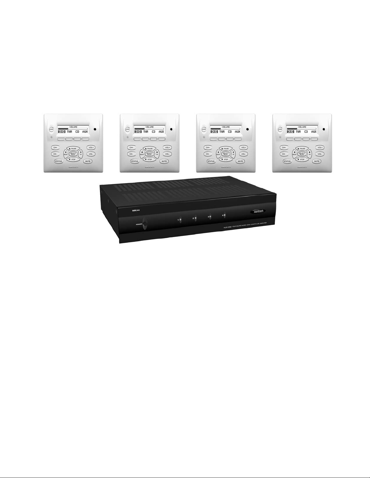
The MRC44 System consists of the MRC44 Controller/Amplifier, four LCD Keypads and four IR Emitters. When
combined with almost any four IR controlled audio/video source components (CD, DVD, VCR, Satellite, etc.),
using the MRC44 System is as easy as pushing a button. The features of the MRC44 are:
The MRC44 system includes the following components:
x One MRC44 Controller/Amplifier(Part No. MRC44CTL)
x Four MRC44 Keypads(Part No. MRC44KPW)
x Four IR Emitters (Part Number 283M)
x One DB9 programming cable to connect to the RS232 serial port on your PC (Part No. 05913410)
x One male DB9 to male DB9 cable with null modem for linking two MRC44 Controllers (Part No. 05913560)
x CD-ROM Disc contains the MRC44 Dragon Drop-IR software (Part No. 03900745-01)
x MRC44 System Installation Instructions (Part No. 08901160)
x Four speaker connector plugs
x 12 Keypad jumpers
x MRC44 Keypad Installation Kit which includes four sets of installation brackets (Part No. 03079545-01), an
installation template (Part No. 09590255), a Keypad removal tool (Part No. 03025280) and the Keypad
Installation Instructions (Part No. 08901175)
x Caution card
Optional Accessories:
x Secondary Keypads - see page 18
White: Part No. MRC44KPW
Black: Part No. MRC44KPB
Almond: Part No. MRC44KPA
Ivory: Part No. MRC44KPI
x External IR Receivers
480-00 Dinky Link™ Series IR Receivers
480-80 CFL Friendly Dinky Link™ Series IR Receivers
490-00 Micro Link™ Series IR Receivers
780 Series J-Box IR Receivers
291 Series Hidden Link™ IR Receivers
x MRC44 Connecting Block (Part No. MRCCB1) – see page 19
x CSM1 Current Sensing Module
x URC2P or URC2B
IMPORTANT NOTE: A MRC44 System can be a single controller with keypads for up to four zones or two
connected controllers and keypads for up to eight zones. There are three different setup modes in the Dragon
Drop-IR Software. The Basic mode allows quick setup and programming for a four zone system. It assumes all
zones will use factory defaults and will behave exactly the same. The Advanced mode allows customization of
system configuration for functions such as zone link, monitor lockout, unique IR programming by zone, etc. The
Expanded mode allows programming of systems with more than four zones using linked MRC44 Controllers.
Each section of this manual will indicate which sections apply to the three programming modes and setups. A
section with: BASIC/ADVANCED/EXPANDED would apply to all system configurations. A section with:
ADVANCED/EXPANDED would only apply to systems requiring advanced programming or that have more
than four zones, etc.
In the Expanded mode, the controller for zones 1-4 will be referred to as the PRIMARY CONTROLLER. The
controller for zones 5-8 will be referred to as the SECONDARY CONTROLLER.
© 2002 Xantech Corporation
Page 5
Model MRC44 Page: 5
SYSTEM OVERVIEW
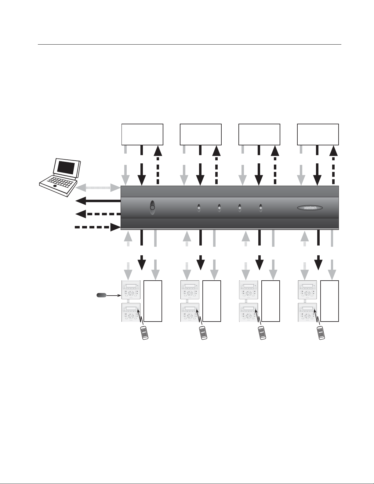
The MRC44 is a four-source four-zone audio/video distribution and control system. The System is comprised of
a Control Amp, four LCD Keypads, and four 283M IR Emitters. Together the Control Amp and the Keypads
make up a multi-room A/V system. The Control Amp acts as the Server and the Keypads act as the Clients.
The end users interact with the Keypads in order to control all aspects of Audio/Video Distribution and Control.
This System allows the end user to accomplish the following: 1) Distribute amplified Stereo Audio and
Composite Video from four independent Sources to four separate Zones. 2) Control the Volume, Mute, Bass,
Treble, and Balance for each of the four internal Stereo Audio Amplifiers. 3) Control most standard source
components via IR commands. Two Control Amps can be linked to create systems with up to eight zones.
DB9 / RS232
Common Status
Common IR
IR Learning Eye
Optional
External IR
Receiver
Primary
Keypad
Optional
Secondary
Keypad
Audio/Video
Source 1
Audio
Power
&
Sense
Video
MRC44
POWER
Zone
Serial
Status
RJ45-
RS422
& IR
Zone 1
POWER
VOL
CH
PAUSE
SELECT
VOL
CH
PLAY
FFREW
STOP
MUTE
STATUS
POWER
VOL
CH
PAUSE
SELECT
VOL
CH
PLAY
FF
REW
STOP
MUTE
STATUS
To Built-In
Keypad
IR Receiver
Audio
&
Video
Zone 1
Video
Monitor
&
Speakers
IR
Primary
Keypad
Optional
Secondary
Keypad
Audio/Video
Source 2
Audio
Power
&
Sense
Video
1234
Serial
Status
RJ45-
RS422
& IR
Zone
Audio
&
Video
IR
Audio
&
Video
Serial
RJ45-
RS422
Zone 2
POWER
CH
PAUSE
SELECT
CH
PLAY
FFREW
STOP
STATUS
POWER
CH
PAUSE
SELECT
CH
PLAY
FF
REW
STOP
STATUS
To Built-In
Keypad
IR Receiver
Zone 2
VOL
VOL
Video
MUTE
Monitor
&
Speakers
VOL
VOL
MUTE
Secondary
Primary
Keypad
Optional
Keypad
POWER
CH
CH
POWER
CH
CH
IR Receiver
Audio/Video
Source 3
Power
Sense
Status
& IR
IR
FOUR ZONE - FOUR SOURCE AUDIO/VIDEO CONTROLLER/AMPLIFIER
Zone
Audio
&
Video
Zone 3
Zone 3
VOL
PAUSE
SELECT
VOL
PLAY
FFREW
STOP
Video
MUTE
STATUS
REW
STATUS
To Built-In
Keypad
Monitor
&
Speakers
VOL
PAUSE
SELECT
VOL
PLAY
FF
STOP
MUTE
Secondary
Primary
Keypad
Optional
Keypad
Audio/Video
Source 4
Audio
Power
&
Sense
Video
Zone
Serial
Status
RJ45-
RS422
& IR
Zone 4
POWER
VOL
CH
PAUSE
SELECT
VOL
CH
PLAY
FFREW
STOP
MUTE
STATUS
POWER
VOL
CH
PAUSE
SELECT
VOL
CH
PLAY
FF
REW
STOP
MUTE
STATUS
To Built-In
Keypad
IR Receiver
Audio
&
Video
Zone 4
Video
Monitor
&
Speakers
IR
Figure 1 - System Block Diagram
© 2002 Xantech Corporation
Page 6

Page: 6 Model MRC44
CONTROLLER/AMPLIFIER FEATURES
Central Processor
x Four Audio/Video Source Inputs
x Video sensing (NTSC/PAL Sync) on each input for power management of common source components
x Current sensing (>20mA-<10A) for each input for power management of common source components and
future control modules using the optional CSM1
x Internal memory (96 Kbytes non-volatile flash) for storing IR codes.
x Programmable only with Dragon Drop-IR Programming Software.
x Recognizes Xantech RC68+ Commands to initiate sequences of IR or amplifier commands.
x Outputs single IR commands or IR sequences.
x Sends "busy" signal to keypads when system is active.
x IR learning eye on back panel of Controller/Amplifier is used as an IR learning port with Dragon Drop-IR™
software.
x DB-9 RS232 Serial port for programming, expansion and upgrading firmware (Future Proof).
x Also available in 230 VAC / 50 Hz.
Zone Features/Specifications
x Each zone has 1 RJ45 connector for MRC44 keypad, 1 composite video output, 1 speaker-pair terminal
and a 12VDC status output.
x Multiple zones can be linked to behave as one zone.
x 25 Watts per channel.
x Frequency response: 12 Hz to 55KHz (±3dB)
x THD: <0.08%.
x Signal-to-noise ratio: > 96dB A-weighted
Five IR Emitter Ports
x Four source specific IR emitter ports and one common IR output.
Software
x Uses Xantech's Dragon Drop-IR™ programming software (included).
x Provides programming of IR codes for control of source components.
x Program sequences of up to 40 IR codes per button.
x Incorporate delays in sequences to allow for amplifier power-up, light dimming, screen drop, drape closure,
etc.
x Allows programming and creation of source icons on keypad displays.
x Associates IR codes to sensed conditions for power management of common sources.
x "Future Proof" feature will allow upgrades for additional system flexibility and control as available.
KEYPAD FEATURES
x Flush-mount, snap-in wall unit with univ ersal wall mounting plate. Requires a 4" x 4" hole cutout in wall
(use included template).
x Configurable LCD panel (via supplied Dragon Drop-IR software).
x 16 buttons (4 source select, 11 function, 1 power).
x Backlit LCD and buttons.
x Variable backlight timeout.
x Bi-colored Status LED for power and status.
x Broadband IR receiver (30KHz to 100KHz).
x Connects to MRC44 Controller/Amplifier via CAT5 cable with RJ45 connectors.
x Two RJ45 connectors allow two keypads per zone.
x Programmable “push-and-hold” on most buttons.
x Optional New Construction backbox (Xantech Part# MRCBOX).
© 2002 Xantech Corporation
Page 7
Model MRC44 Page: 7
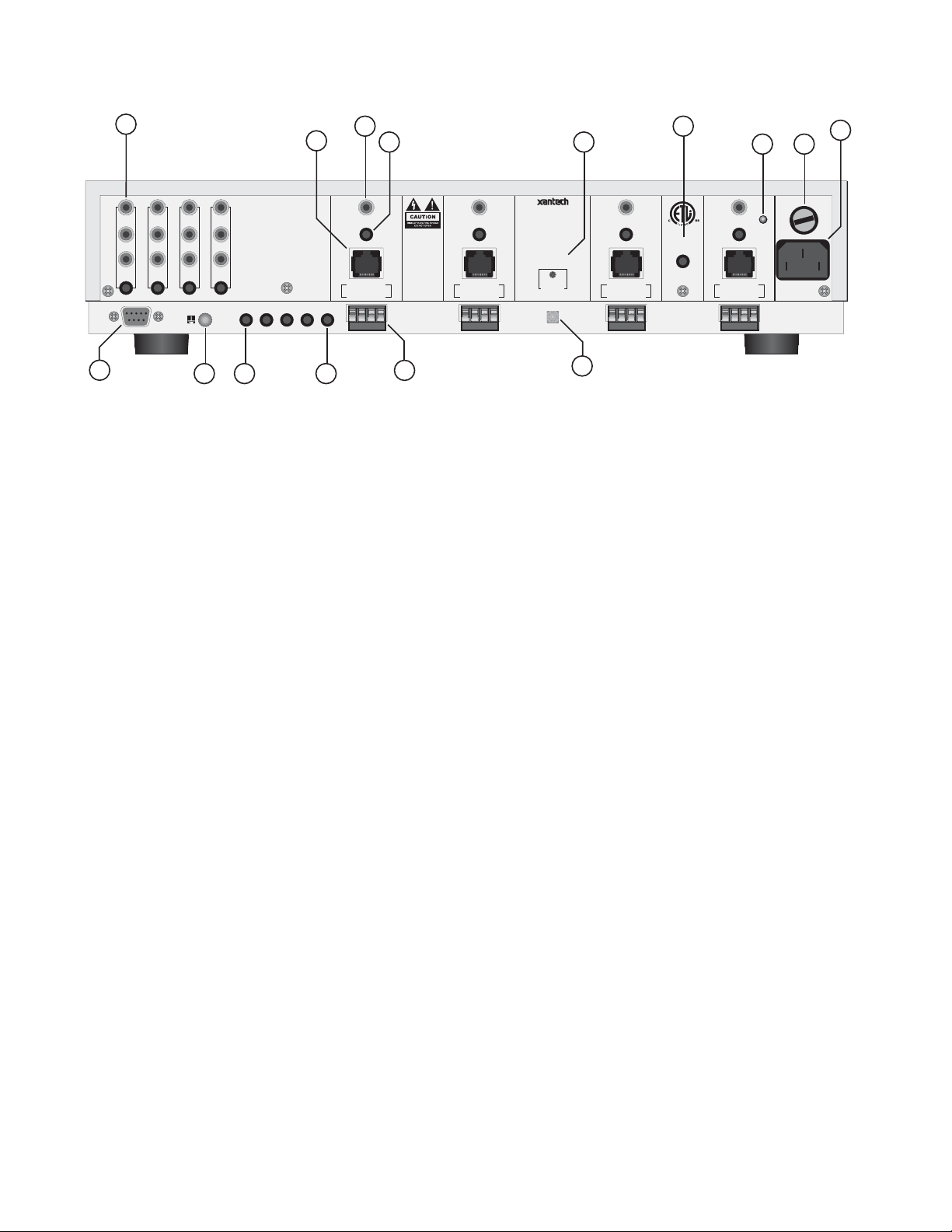
MRC44 CONTROLLER/AMPLIFIER PANEL AND FEATURE DESCRIPTIONS
1
MRC44
POWER
1234
FOUR ZONE - FOUR SOURCE AUDIO/VIDEO CONTROLLER/AMPLIFIER
3
2
4
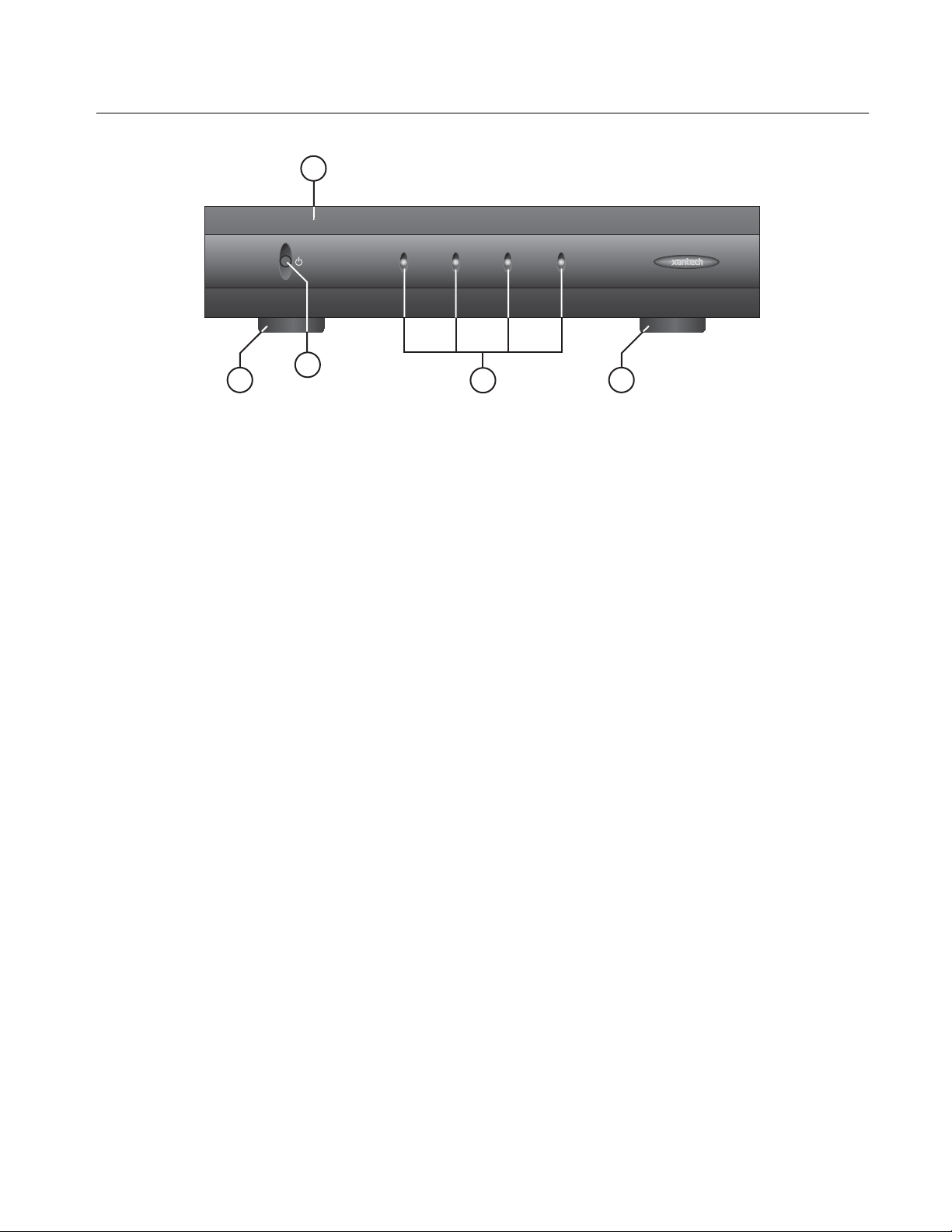
Figure 2 – The Model MRC44 Controller/Amplifier – Front Panel Features and Functions
1. Front Panel.
2. Chassis Feet. Set high enough to provide through-chassis cooling by natural convection.
3. Master AC Line On/Off Switch. Turns AC power On/Off to the entire unit.
4. Power and Status LED Indicators. Four indicators, one for each Zone, prov ide the following status
information:
System Status (Power-Up Mode)
a) Slow Orange Blink – indicates general initialization is occurring.
b) Fast Green Blink – indicates that a keypad on the associated zone is currently being initialized.
c) Fast Red Blink – indicates that the master keypad on the associated zone is not responding to
initialization.
d) Fast Orange Blink – indicates that the slave keypad on the associated zone is not responding to
initialization.
e) All Lights Off – initialization is done, system is ready for operation.
Zone Status (Operational Mode)
a) Steady Green to indicate that Zone is in the Power-Up Mode, is not muted and is not within 5 dB of
MAX-V.
b) Steady Red to indicate that Zone is in the Power-Up Mode, is not muted and is within 5 dB of MAX-V.
c) Flash Green to indicate that Zone is in the Power-Up Mode, is muted and is not within 5 dB of MAX-V.
d) Flash Red to indicate that Zone is in the Power-Up Mode, is muted and is within 5 dB of MAX-V.
e) Flash Green to indicate that Zone is in the Power-Up Mode, is not muted, is not within 5 dB of MAX-V
and is being Ramped Up or Down.
f) Flash Red to indicate that Zone is in the Power-Up Mode, is not muted, is within 5 dB of MAX-V and is
being Ramped Up or Down.
g) Off to indicate that Zone is in the Power-Down Mode.
2
© 2002 Xantech Corporation
Page 8
Page: 8 Model MRC44
11
1234
SENSE SENSE SENSE SENSE
COM
PORT
14
AUDIO LEFT
AUDIO RIGHT
VIDEO
GND
IR OUT
5
WARNING: TO REDUCE THE
RISK OF FIRE OR ELECTRICAL
SHOCK, DO NOT EXPOSE
THIS UNIT TO RAIN,
MOISTURE OR PLACE WATER
FILLED OBJECTS ON THE
PRODUCT.
ATTENTION: RISQUE DE
CHOC ELECTRIQUE
NE PAS OUVRIR.
NO USER SERVICABLE
PARTS INSIDE.
REFER TO OWNERS MANUAL
FOR SAFETY INSTRUCTIONS.
1 2 3 4 COMMON
7
8
VIDEO
12 34
STATUS
K
E
Y
P
A
D
SPEAKER
LEFT RIGHT
131218
DINSTRUCTIONS.
LOUDSPEAKERS
+-- --+
6
ATTENTION:
POUR UN
REGLAGE
CORRECT, SE
REPORTER AU
MANUEL
USE CLASS 2
WIRING FOR
VIDEO
STATUS
K
E
Y
P
A
D
LEFT RIGHT
SPEAKER
CONTROLLER / AMPLIFIER
THIS DEVICE COMPLIES WITH PART 15
OF THE FCC RULES. OPERATION IS
SUBJECT TO THE FOLLOWING TWO
CONDITIONS: (1) THIS DEVICE MAY NOT
CAUSE HARMFUL INTERFERENCE, AND
(2) THIS DEVICE MUST ACCEPT ANY
INTERFERENCE RECEIVED, INCLUDING
INTERFERENCE THAT MAY CAUSE
UNDESIRED OPERATION.
+-- --+
MODEL MRC44
LEVEL
RESET
IR
10
15
VIDEO
STATUS
K
E
Y
P
A
D
LEFT RIGHT
SPEAKER
9
17
19 1616
VIDEO
STATUS
CONTROL
OUT
K
E
Y
P
A
D
SPEAKER
+-- --+
LEFT RIGHT
CAUTION
NEUTRAL FUSING
+-- --+
FUSE 6 AMP
SLOW BLOW
AC 120V
60 HZ 3A
240 WATTS
Figure 3 – The Model MRC44 Controller/Amplifier – Rear Panel Features and Functions
5. Keypad Terminals. Each Zone has one RJ-45 jack for Keypad Interface. Each connector interfaces the
following: Power (Enough for 1 Primary & 1 Secondary Keypad per Zone), RS-422 Data I/O, and IR Input.
6. Speaker Terminals. Plug-in 4-terminal screw type connectors permit speaker wire sizes up to 12 gauge.
7. Composite Video Output. RCA type connector sends zone selected source v ideo to the composite video
input on a zone TV or modulator.
8. Status. Provides a control output of +12 VDC that turns on and off with the zone to drive v oltage sensing
relay modules and AC strips.
9. Control Out. Provides a Control Output that goes high (+12 volts) when any zone is first turned on and
goes low (0 volts) when the last zone is turned off.
10. Level Reset. Pressing this button twice within 1 second restores all of the Factory Default Settings for all
zones. The Factory Defaults are as follows:
x Mute Off
x Treble and Bass Flat
x Balance Centered
x Z-Adjust Treble and Bass Flat
x Z-Adjust Balance Centered
x Z-Adjust Max-V Cleared
x Trim Levels Cleared
x IR Code Group set to 48
NOTE: The Control Amp will always return to last set values (plus any unaltered factory defaults) after main
power shut down or after any power interruptions.
11. Source Component Connections
a) Source Audio Inputs. Gold-plated RCA Jacks for line level audio input from source components.
b) Source Video Inputs. Gold-plated RCA Jacks for composite video input from source components.
c) Sense Inputs. 3.5mm Stereo Mini Phone Jacks for use with the CSM1 MRC44 Current Sense Module.
© 2002 Xantech Corporation
Page 9

Model MRC44 Page: 9
12. IR Out (1-4). 3.5mm Mono Mini Phone Jacks. These mini jacks are for the connection of IR emitters to
control source components. These jacks are “steerable” with Dragon Drop-IR for IR routing and priority
lockout. (See: Controller Options Programming.)
13. IR Out (Common). 3.5mm Mono Mini Phone Jacks. The Control Amp has a single Common IR Output that
can be used to control devices such as motorized drapery systems, TV lifts and lighting systems.
14. Com Port. DB9 Connector. This Serial Port is used to program the MRC44 Controller and Keypads using
the included Dragon Drop-IR Software from a PC. Also used for linking multiple MRC44 Controllers in
Expanded Configurations.
15. IR Learning Eye. The IR Eye on the MRC44 Controller back panel allows teaching IR Codes to Dragon
Drop-IR via the Control Amp when connected to a PC from the com port.
16. User Replaceable Fuse. 6.25 AMP 250 VAC, Slow Blow Fuse (Domestic version). 3.15 AMP 250 VAC,
Time-Lag Fuse (European version).
17. AC Power Input. Standard IEC 3-Conductor AC Line Cord Receptacle for plug-in of a 3-conductor power
line cord.
18. Grounding Screw. “Knurled Screw” provides a means for chassis connection to earth ground or to other
Audio/Video products to aid in the reduction of system noise.
19. Power On/Off LED. This LED indicates the Main Power ON/OFF Condition of the MRC44 Controller.
© 2002 Xantech Corporation
Page 10
Page: 10 Model MRC44
MRC44 KEYPAD FEATURE DESCRIPTIONS
21
23
25
32
33
34
20
24 22
POWER
CH
CH
STATUS
REW
26 27
PAUSE
SELECT
PLAY
STOP
28
VOL
FF
VOL
MUTE
29
30
31
35
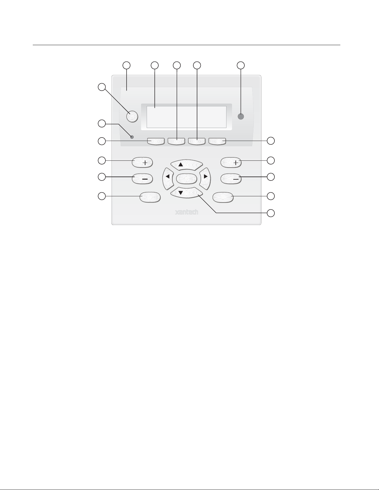
Figure 4 – The Model MRC44 Keypad – Front Panel Features and Functions
20. MRC44 Keypad.
21. Power. Turns the zone ON and OFF. Can be programmed with IR codes or sequences.
22. IR Sensor. Receives IR from hand-held remotes to control both source components and the MRC44
system. A Programmable Learning Remote such as the Xantech URC2 is recommended for integrating the
IR commands of the MRC44 and source components into a single controller. Compatible with most brands
of remote controls, though some may not be programmable and will therefore only control the source
components.
23. Status Indicator LED. Will indicate zone/system status and will flash as IR is received at the IR Sensor.
These indicators, one for each Keypad, provide the following Information:
a) Off=Zone OFF
b) Steady Green=Zone ON
c) Flash Green=Zone MUTE
d) Flash Red=IR Sensor INPUT or Keypad OUTPUT
e) Flash Amber=System BUSY
24. LCD Display. When the zone power is ON, the LCD will indicate the selected source, zone and system
status, zone volume level and other system conditions. The display is automatically backlit when any button
is pressed.
25. Source 1 Selector. Selects source input 1, reverses source icon on LCD Display when source is selected
and sends IR commands programmed to this button (if any) to the source 1 and common emitter outputs.
Also used in Dynamic Monitor Lockout and Dynamic Zone Link Modes.
© 2002 Xantech Corporation
Page 11
Model MRC44 Page: 11
26. Source 2 Selector. Selects source input 2, reverses source icon on LCD Display when source is selected
and sends IR commands programmed to this button (if any) to the source 2 and common emitter outputs.
Also used in Dynamic Monitor Lockout and Dynamic Zone Link Modes.
27. Source 3 Selector. Selects source input 3, reverses source icon on LCD Display when source is selected
and sends IR commands programmed to this button (if any) to the source 3 and common emitter outputs.
Also used in Dynamic Monitor Lockout and Dynamic Zone Link Modes.
28. Source 4 Selector. Selects source input 4, reverses source icon on LCD Display when source is selected
and sends IR commands programmed to this button (if any) to the source 4 and common emitter outputs.
Also used in Dynamic Monitor Lockout and Dynamic Zone Link Modes.
29. Vol
+. Increases zone volume and moves the Volume Bar on the LCD Display to indicate volume level
(non-programmable).
30. Vol
-. Decreases zone volume and moves the Volume Bar on the LCD Display to indicate volume level
(non-programmable).
31. Mute. Mutes zone speaker output. Sends IR commands programmed to this button (if any) to the selected
source and common emitter outputs.
32. CH
33. CH
+. Sends IR commands programmed to this button to the selected source and common emitter outputs.
-. Sends IR commands programmed to this button to the selected source and common emitter outputs.
34. Status. Displays zone and system status (zone/source activ ity, linked zones, audio setup, etc – non-
programmable).
35. Select/Play, Stop, Pause, Rew, FF. Each send IR commands programmed to these buttons to the
selected source and common emitter outputs.
4337 36
41
42
43
38
39
40
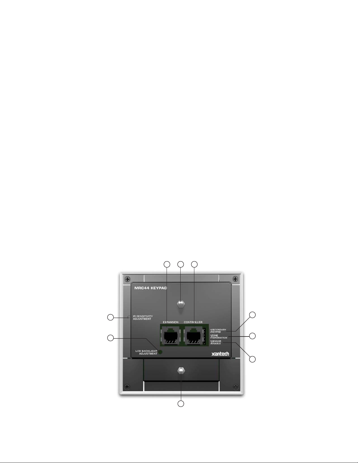
Figure 5 – The Model MRC44 Keypad – Rear Panel Features and Functions
© 2002 Xantech Corporation
Page 12

Page: 12 Model MRC44
36. Controller Terminal. RJ45 Jack. Connects Keypad to zone keypad input on MRC44 Controller via CAT5
cable.
37. Expansion Terminal. RJ45 Jack. Allows a second Keypad or external IR receiver for each zone.
38. Secondary Keypad. Jumper. Used to configure as secondary keypad in zone.
39. Zone Termination. Jumper. Do not remove jumper if there is only one keypad in a zone. If there are two
keypads in a zone, remove only from the first keypad.
40. Enable Sensor. Jumper. Enables IR sensor on Keypad. Remove when using an external IR receiver.
41. IR Sensitivity Adjustment. Carefully adjust for background light level to prevent false triggering of the IR
circuits. Slowly turn counter-clockwise to reduce sensitiv ity.
42. LCD Backlight Adjustment. Adjusts brightness of LCD backlight. This adjustment does not affect the
backlight level for the buttons. Slowly turn counter-clockwise to reduce brightness.
43. Snap-in Pins. These pins snap into the MRC44 Keypad wall bracket for mounting.
OPERATION – OUT-OF-THE-BOX
(BASIC/ADVANCED/EXPANDED)
The Controller/Amplifier Out-of-the-Box feature will verify that all sources and zone components are working
properly to select and distribute audio and video prior to programming with Dragon Drop-IR™. Programming for
specific components and features follows.
1. Connect MRC44 Controller/Amplifier as shown in Figure 13 to:
a) MRC44 Keypads
b) Speakers
c) TVs or Monitors
d) AC Power
e) Sources
f) IR emitters
2. Press “Power On” button on the front of the MRC44 Controller/Amplifier (wait for front panel LEDs to stop
flashing – should be less than 20 seconds).
3. Turn on the Zone 1 TV/monitor and select the appropriate input (on the TV or monitor).
4. Turn on all sources and press play on all source components.
5. Press “POW ER” on the Zone 1 Keypad.
6. Select “SRC1” on the Zone 1 MRC44 Keypad.
a) If Source 1 is an Audio/Video component, the video content of the source connected to the Source 1
inputs should be seen on the zone 1 TV/monitor.
b) Press “VOL+” on the Zone 1 Keypad. The Volume bar should mov e on the Keypad and the audio
content of the source connected to the Source 1 inputs should be should be heard through the Zone 1
speakers.
c) Press “MUTE” on the Zone 1 Keypad. The Zone 1 speakers will mute. Press MUTE again and the
speakers will un-mute. (Pressing VOL+ or VOL- will also un-mute the speakers).
d) Use the source 1 original equipment remote and verify that all source functions operate when aiming
the remote at the Zone 1 Keypad IR sensor.
e) Repeat above for all zones and sources.
© 2002 Xantech Corporation
Page 13

Model MRC44 Page: 13
INSTALLATION
MRC44 CONTROLLER/AMPLIFIER PHYSICAL LOCATION AND MOUNTING
(BASIC/ADVANCED)
When you mount the MRC44 Controller, you should plan its location carefully. Pay close attention to each of
the following factors:
1. The amplifier is convection cooled. That is, it depends on the natural free flow of air up through the slot
perforations in the bottom plate, over the internal heat dissipating fins, then out the top cover, for adequate
cooling.
2. If mounted in an equipment cabinet or other confining location, allow at least 2 inches of space above the
top cover. Be sure there are large openings in the shelf below the unit and in the cabinet to allow the entry
of cool air and the escape of warm air.
3. If the cabinet contains other heat generating components or you are using several MRC44's in a large multizone system, you will have to pay even closer attention to adequate ventilation.
4. Do not hesitate to use fans (quiet, boxer type), if necessary, to ensure a constant flow of air through the
MRC44's and the other heat generating components.
5. When mounting in a 19" (483mm) rack, adding a single RU (Rack Unit) spacer abov e and below the
MRC44 will improve convection in heavy use applications.
[One Rack Unit size = 1-3/4" (44.5mm) in height].
6. In multi-zone installations, you will have large bundles of wire and cable to accommodate audio, video and
speaker connections. Be sure to allow enough room for the leads and dress them in such a manner so as
not to block airflow.
7. The MRC44 is designed for mounting on flat horizontal surfaces. When mounting into a 19" rack, use a rack
shelf or drawer.
8. Do not remove chassis feet. They are necessary to provide proper ventilation.
NOTE: You should consider some sort of rear support for rack mounted units when used in mobile
applications or when located in seismically active areas.
(EXPANDED)
Place Controllers on separate shelves or provide 2 inches of space between Controllers for ventilation.
MRC44 KEYPAD PHYSICAL LOCATION AND MOUNTING
(BASIC/ADVANCED/EXPANDED)
MRC44
Keypad
RJ45
Connector
Figure 6 - Mounting and Installing the MRC44 Keypad
Ground
Lug
Cat 5
Cable
To Earth Ground
© 2002 Xantech Corporation
Page 14

Page: 14 Model MRC44
Keypad mounting for the MRC44 Keypad does not require a junction box. The MRC44 keypad can be mounted
on drywall, lath & plaster, button board or other surfaces covering a hollow wall. Follow these simple
procedures to install the provided MRC44 mounting bracket and keypad:
NOTE: Check local electrical codes. Some areas require a backbox in certain applications. For installations that
require a backbox, see Xantech Part# MRCBOX. The MRC44 keypad will not fit in a standard 2-gang box. The
Xantech MRCBOX must be used in applications that require a backbox.
1. Cutting the hole
a. Mark the desired mounting location for the center of the keypad.
b. Using a level, make proper horizontal and v ertical marks on surface to be cut, to properly orient
template.
Figure 7 – MRC44 Keypad mounting template
c. Locate the provided template so that the mark is in the center of the hole, which is in the center of the
template.
d. Rotate the template around the center until the template is level.
e. Press or hammer the template in place so that the holding tabs pierce the wall and hold the template in
place.
f. Mark or scribe the outline of the template on the wall.
g. Remove the template and cut a clean hole through the wall along the outline of the template, being sure
that your cut is on the outline. Any cut outside of the outline by more than ¼” may not be covered by the
MRC44 Keypad.
1
2
Figure 8 – Installing the MRC44 Keypad mounting bracket in the wall
© 2002 Xantech Corporation
Page 15
Model MRC44 Page: 15
2. Installing the Mounting Bracket
a. Attach the ground wire to the ground lug to the rear of the back-bar with the provided green screw,
before beginning the bracket installation process.
NOTE: A ground wire connected to Earth ground is required to protect against static discharge.
b. Run the supplied screws through the top (marked on the front of the bracket) of the mounting bracket
into the back-bar as shown in Figure 8.
c. Pull the CAT5 cable through the hole in the wall.
d. Pull the CAT5 cable through the hole in the mounting bracket.
e. Slide the left or right side of the back-bar into the wall.
f. Center the mounting bracket in the wall and tighten the screws until the bracket is firmly held in the wall.
Over tightening will distort the bracket and prevent the Keypad from snapping tight against the wall.
Under tightening will cause the Keypad to be loose against the wall.
g. If there is not enough room to slide the keypad in as described above, you can hold the back-bar in
place as you run the screws through the mounting plate and into the back-bar. TIE A LONG STRING
TO THE BACK-BAR so that you can easily retrieve it in case you drop the back-bar into the wall!
3. With the Controller/Amplifier turned off, connect the CAT5 cable to the appropriate RJ45 connector, using
Figure 10 as a guide for CAT5 termination.
4. Add or remove jumpers on the rear of the MRC44 keypad-according to Table 1 (Keypad connections).
5. Firmly snap the MRC44 Keypad into the bracket that you have just installed (see Figure 6).
6. Confirm all Keypad operations.
MRC44 KEYPAD REMOVAL
POWER
CH
CH
STATUS
REW
PAUSE
SELECT
PLAY
STOP
VOL
VOL
FF
MUTE
1
2
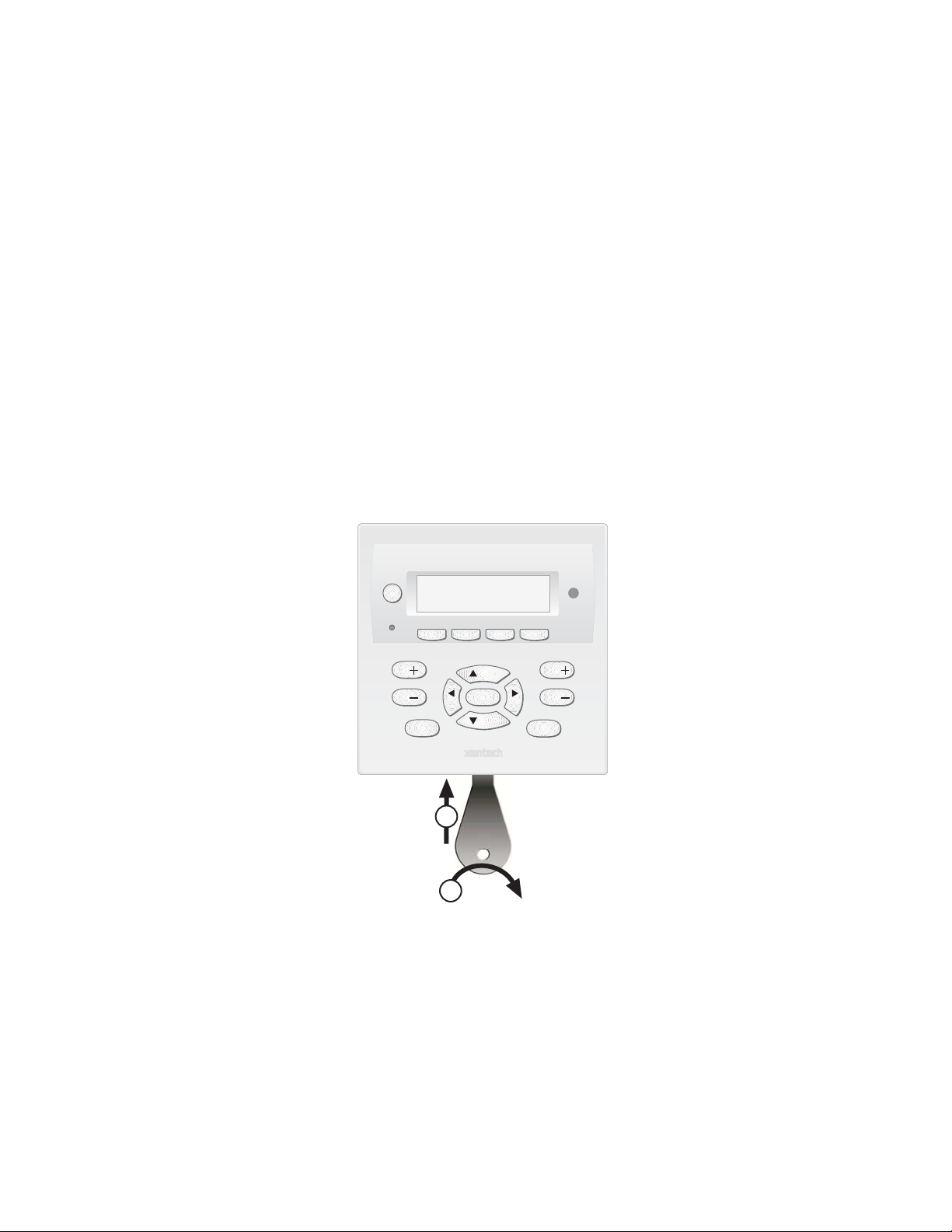
Figure 9 – Removing the MRC44 Keypad from the wall
1. Insert the MRC44 keypad remov al tool into the slot at the bottom of the keypad, as shown in Figure 9,
being sure that the tool is inserted so that the “insert to here” line slides under the Keypad. This will reduce
the risk of damage to the Keypad or the wall.
2. Twist the removal tool in either direction until the bottom of the Keypad pulls away from the wall, then
carefully grip the edges of the Keypad with your fingers and pull it off the wall.
NOTE: Since the Keypad snaps into the mounting bracket and there are a large variety of wall textures, the
Keypad may POP OUT or require some additional effort to pull it off the wall, depending on your particular
installation.
© 2002 Xantech Corporation
Page 16

Page: 16 Model MRC44
CONNECTING THE MRC44 CONTROLLER/AMPLIFIER
When making connections to the MRC44 Controller be sure the power cord is unplugged. Proceed as follows,
referring to Figure 13 for Typical MRC44 System layout:
Source Component Connections
Audio Connections
(BASIC/ADVANCED)
Using good quality RCA-type patch cables connect the LEFT and RIGHT OUTPUT jacks of the source
component (DVD, CD, Satellite receiver, etc.) to the appropriate LEFT and RIGHT INPUT jacks on the
MRC44. Do this for each source component. Refer to Figure 13.
(EXPANDED)
Using good quality RCA-type patch cables connect the LEFT and RIGHT OUTPUT jacks of the source
component (DVD, CD, Satellite receiver, etc.) to the LEFT and RIGHT INPUT jacks on a Xantech AV61
Audio/Video Distribution Amplifier. Connect the LEFT and RIGHT OUTPUT jacks of the AV61 to the
appropriate LEFT and RIGHT INPUT jacks both MRC44 Controllers. Do this for each source component.
Refer to Figure 24. See text: “Zone Expansion” AV61 Connections.
Video Connections
(BASIC/ADVANCED)
Using good quality RCA-type video patch cables connect the VIDEO OUTPUT jacks of the source
component to the VIDEO INPUT jacks on the MRC44. Do this for each source Component. Refer to
Figure 13.
(EXPANDED)
Using good quality RCA-type patch cables connect the VIDEO OUTPUT jacks of the source component to
the VIDEO INPUT jacks on a Xantech AV61 Audio/Video Distribution Amplifier. Connect the VIDEO
OUTPUT jacks of the AV61 to the appropriate VIDEO INPUT jacks both MRC44 Controllers. Do this for
each source component. Refer to Figure 24. See text: “Zone Expansion” AV61 Connections.
IR Control Connections
(BASIC/ADVANCED)
Plug the supplied 283M IR emitters into the appropriate IR out jacks. Be careful to match the source audio
and video connection number on the MRC44 to the IR emitter jack number. This will ensure that the IR
control signal will be routed to the correct source component. Find the IR sensor window on the source
component and attach the emitter to the sensor window after removing the protective paper cover on the
flat side of the emitter head. A common IR jack is also provided for connection to other auxiliary devices.
(EXPANDED)
Connect the emitters as in Figure 24 using one 793-10 Serial Control Combiner for each common source
component that is to be controlled by both Controllers. See text: “Zone Expansion” 793-10 Connections.
Sense Input Connections
(BASIC/ADVANCED)
The sense input connection will typically be used to sense the power state of a source component using the
Xantech CSM1 Current Sense Module. Plug the 3.5mm miniplug from the CSM1 into the appropriate sense
jack. Be careful to match the source audio and video connection number on the MRC44 to the sense jack
number. The CSM1 plugs into an AC power source. The component power cord plugs into the CSM1.
CSM1 Threshold Adjustments
a. Manually turn the component ON first.
b. Using a small (1/8” wide) blade screwdriver, rotate the current control to a full counter-clockwise
position.
c. Rotate the control clockwise until the Threshold Adjustment LED goes OFF.
d. Manually turn the component OFF
e. Rotate the control until the Threshold Adjustment LED just goes ON.
f. Set the control to a point midway between these two settings. This should be the correct setting.
NOTE 1: If the Threshold Adjustment LED does not go ON and OFF with the component power mode,
make minor adjustments to the threshold adjust until the LED is in proper sync.
© 2002 Xantech Corporation
Page 17

Model MRC44 Page: 17
NOTE 2: Program IR commands fro MRC44 Controller current sensing as described in
“PROGRAMMING SENSE CODES”.
(EXPANDED)
Connect CSM1’s as described above to the Primary Controller. Sense inputs are not available on the
Secondary Controller.
Zone Wiring Connections at the MRC44 Controller/Amplifier
(BASIC/ADVANCED/EXPANDED)
In typical applications, each zone will have at least one MRC44 Keypad and a pair of stereo speakers. In
those zones with both audio and video, at least one video monitor or television will also be used. In order to
make these connections, the minimum requirement is home runs of one CAT5 cable for each zone’s
keypad(s), two pairs for each pair of speakers, and one coaxial cable for a TV or monitor from each zone to
the MRC44 Controller/Amplifier location.
Speaker Connections
(BASIC/ADVANCED/EXPANDED)
1. Using good quality speaker wire, connect the individual speaker leads to the 4-terminal "SPEAKER"
connectors on the MRC44 as shown in Figure 3.
2. The MRC44 is 4-Ohm safe. Make sure the impedance presented to the speaker terminals by the speakers
(or any combination of speakers) is 4-Ohms minimum.
3. Be sure to observe correct polarity by connecting the "+" and "–" terminal from each channel on the MRC44
to the corresponding "+" and "–" terminals on each speaker. This will ensure correct "phasing". Since the
connectors are removable, you may unplug them for ease of lead assembly.
4. As a rule of thumb, use 18 gauge speaker wire for speaker runs up to 30' (9m), 16 gauge up to 70' (21m),
and 14 gauge up to 150' (39m). The 4-terminal connectors accept wire sizes up to 12-gauge max.
5. Strip the insulation back about 1/4" (6mm) and twist the strands on each lead to prevent fraying.
6. Speaker Phasing: To obtain stable imaging and full bass response, it is imperative that stereo speakers be
connected "in phase" with each other. You can verify this as follows:
a) If the "+" (positive) and "–" (negative) terminals on your speakers are correctly marked, and visible, and
you have wired the system with the positive connector on the rear of the MRC44 Controller/Amplifier
connected to the positive connector on the speaker and the negative connector on the rear of the
MRC44 Controller/Amplifier connected to the negative connector on the speaker, then the system will
be "in phase". No further action is required. Most manufacturers identify the positive terminal with a red
binding post, a "+" sign, or a red dot.
b) If you are unsure of the markings, you can verify the phasing. Using a mono sound source, such as AM
radio, alternately reverse the leads to one of the speakers. Pick the connection that delivers a solid
center image between the speakers as well as best bass response.
CAUTION: After lead ends are inserted and the screws tightened down, be sure there are no free strands
that could cause shorting!
© 2002 Xantech Corporation
Page 18

Page: 18 Model MRC44
RJ45 Connector at
Controller/Amplifier
Wire Color Signal
white/orange Tx+
orange Txwhite/green 12V RET
blue IR RET
white/blue IR
green +12V
white/brown Rx+
brown Rx-
Cat 5
Cable
Figure 10 - CAT5 Pin Assignments (per EIA/TIA 568B)
MRC44 Keypad Cable Connections at the MRC44 Controller/Amplifier
(BASIC/ADVANCED/EXPANDED)
1. See Figure 10 for termination of the CAT5 cables to the RJ45 connectors.
2. Connect the zone keypad to the appropriate zone Keypad connector on the rear of the MRC44
Controller/Amplifier.
Video Connections
(BASIC/ADVANCED/EXPANDED)
Composite Video
1. When running composite video to a TV or monitor, use RG-6 coaxial or RG-59 quadshield cable with RCA
type phono plugs on each end. This connection can be run for 150 feet, as this is a buffered video output
from the MRC44 Controller/Amplifier.
2. Connect the zone video cable to the appropriate zone video jack on the rear of the MRC44 Controller/
Amplifier.
Modulated Video
3. When modulating the zone video output and using the RF/ANT input to a television, connect the VIDEO
OUTPUT from the MRC44 Controller to the VIDEO INPUT of a Modulator, using high quality RCA type
video patch cords. Use RG-6 coaxial cable with "F" connectors on each end to connect the Modulator, to
the RF/ANT IN on the room TV.
RJ45 Connector
at Keypad
Wire Color Signal
white/orange Rx+
orange Rxwhite/green 12V RET
blue IR RET
white/blue IR
green +12V
white/brown Tx+
brown Tx-
Control Out and Status Connections
Status
(BASIC/ADVANCED/EXPANDED)
Each zone has a Status Output that provides a control output of +12 VDC, 50mA that turns on and off with
the zone ON/OFF condition. ON = +12VDC, OFF = 0VDC. Using a 3.5mm mono mini phone connector, this
control can be used to close a relay, such as a Xantech CC12, to raise a TV lift or drop a projection screen
automatically when a zone is turned ON.
Control Out
(BASIC/ADVANCED)
A single Common Control Output is provided. When the Common Control Output is High (+12 volts, 50
mA), this indicates that at least one zone is ON. When the Common Control Output is Low (0 volts), this
indicates that all zones are OFF. Using a 3.5mm mono mini phone connector, this control can be used to
close relays (Xantech CC12) or turn on an AC outlet (Xantech AC1, AC2) for activity common to the
system.
© 2002 Xantech Corporation
Page 19

Model MRC44 Page: 19
(EXPANDED)
When at least one zone on either the PRIMARY or SECONDARY controller is turned ON, the Control Out
on the PRIMARY Controller is High (+12 volts). The Control Out on the SECONDARY Controller will be
inactive.
AC Power Connections
(BASIC/ADVANCED/EXPANDED)
Use the supplied power cable and plug into a power source capable of delivering the rated amps shown in
the specification section of this manual.
CONNECTIONS AT THE ZONE LOCATION
(BASIC/ADVANCED/EXPANDED)
Single Keypad Connections
1. Refer to Figure 10 for proper termination at the zone-end of the CAT5 cable.
2. Connect the CAT5 cable from the MRC44 Controller/Amplifier into the RJ45 jack marked “Controller” on the
rear of the MRC44 keypad.
3. Depending on the number of MRC44 keypads and IR receiv ers used in a zone the jumper pins on the
MRC44 keypad are to be connected as shown in the following table:
Primary Keypad Secondary Keypad
Application
One keypad in Zone with IR
Sensor enabled
Two Keypads in Zone with IR
Sensors enabled
One Keypad and one separate
IR Receiver in Zone
Secondary
Keypad
OFF ON ON
OFF OFF ON ON ON ON
OFF ON OFF
Zone
Termination
Sensor
Enable
Secondary
Keypad
Zone
Termination
Sensor
Enable
Two Keypads and two separate
IR Receivers in Zone (Sub-
OFF OFF OFF ON ON OFF
Zone)
Table 1 – MRC44 Keypad Jumper Configurations
Multiple Keypad Connections
1. For a second keypad in the same zone, terminate the CAT5 cable in the same way as shown in Figure 10.
2. Connect the CAT5 coming from the MRC44 Controller to the “CONTROLLER” jack on the Primary Keypad.
Plug a CAT5 cable into the “EXPANSION” jack on the Primary Keypad and connect it to the
“CONTROLLER” jack on the Secondary Keypad. Set the jumpers according to the above Table 1.
3. When adding an IR receiver in the zone, set the jumpers according to the above table and connect the
cables as shown in Figure 11.
© 2002 Xantech Corporation
Page 20

Page: 20 Model MRC44
Extended Runs and Secondary Keypad In Zone
400 feet max (122 m)
A
B
MRC44
POWER
1234
FOUR ZONE - FOUR SOURCE AUDIO/VIDEO CONTROLLER/AMPLIFIER
POWER
CH
CH
200 feet max (61 m)
MRC44
POWER
1234
FOUR ZONE - FOUR SOURCE AUDIO/VIDEO CONTROLLER/AMPLIFIER
POWER
VOL
CH
PAUSE
SELECT
VOL
CH
PLAY
FFREW
STOP
MUTE
STATUS
POWER
CH
CH
IR Receiver
VOL
PAUSE
SELECT
VOL
PLAY
FFREW
STOP
MUTE
STATUS
IR Receiver
VOL
PAUSE
SELECT
VOL
PLAY
FFREW
STOP
MUTE
STATUS
C
IR Receiver
MRC44
POWER
1234
FOUR ZONE - FOUR SOURCE AUDIO/VIDEO CONTROLLER/AMPLIFIER
POWER
VOL
CH
PAUSE
SELECT
VOL
CH
PLAY
FFREW
STOP
STATUS
MUTE
PWR
MRC44
Connecting
Block
IR RCVR
VGS
POWER
CH
CH
IR Receiver
VOL
PAUSE
SELECT
VOL
PLAY
FFREW
STOP
STATUS
MUTE
200 feet max (61 m)
782-00
To 120 V AC
(unswitched)
Power Supply
IR Receiver
400 feet max (122 m)
IR RCVR
PWR
MRC44
D
MRC44
POWER
1234
FOUR ZONE - FOUR SOURCE AUDIO/VIDEO CONTROLLER/AMPLIFIER
POWER
VOL
CH
PAUSE
SELECT
VOL
CH
PLAY
FF
REW
STOP
MUTE
STATUS
VGS
Connecting Block
POWER
IR Receiver
VOL
CH
PAUSE
SELECT
VOL
CH
PLAY
FF
REW
STOP
MUTE
STATUS
600 feet max (183 m)
Figure 11 – MRC44 Keypad CAT5 Cable Lengths
The maximum cable length for CAT5 connections to a single keypad is 400 feet (see Figure 11-A). For two
keypads in a zone, the distance to the last keypad is 200 feet (see Figure 11-B).
MRCCB1
PWR
VGS
IR IN
CONTROLLER KEYPAD
Figure 12 – MRCCB1 MRC44 Connecting Block
If both keypads in the zone are using an external IR receiver, the MRC44 Connecting Block (see Figure 12)
is used to expand the connections on the back of the primary keypad as shown in Figure 11-C.
If your installation requires cabling beyond these limits you can use the MRC44 Connecting Block to power
the keypads from a separate run of +12VDC as shown in Figure 11-D. The +12VDC can also be
generated in the zone from a model 782 power supply or from a source at the Controller/Amplifier location
(run an 18 gauge speaker wire to the MRC44 Connecting Block to minimize line loss. This method will
extend the distance to the last keypad in the zone to a maximum of 600 feet.
The Maximum cable run to the external IR receiver in each of the above cases is 250 feet from the keypad.
© 2002 Xantech Corporation
Page 21

Model MRC44 Page: 21
Speaker Connections
(BASIC/ADVANCED/EXPANDED)
SPEAKER PHASING: TO OBTAIN STABLE IMAGING AND FULL BASS RESPONSE, IT IS IMPERATIVE
THAT STEREO SPEAKERS BE CONNECTED "IN PHASE" WITH EACH OTHER. YOU CAN VERIFY THIS
AS FOLLOWS:
1. If the "+" (positive) and "–" (negative) terminals on your speakers are correctly marked, and visible, and you
have wired the system with the positive speaker connector on the rear of the MRC44 Controller/Amplifier
connected to the positive connector on the speaker and the negative speaker connector on the rear of the
MRC44 Controller/Amplifier connected to the negative connector on the speaker, then the system will be "in
phase". No further action is required. Most manufacturers identify the positive terminal with a red binding
post, a "+" sign, or a red dot.
2. If you are unsure of the markings, you can verify the phasing. Using a mono sound source, such as AM
radio, alternately reverse the leads to one of the speakers. Pick the connection that delivers a solid center
image between the speakers as well as best bass response.
CAUTION: After lead ends are inserted and the screws tightened down, be sure there are no free strands
that could cause shorting!
Video connections
(BASIC/ADVANCED/EXPANDED)
Composite Video
The buffered, composite video output from the MRC44 Controller/Amplifier will drive a VIDEO INPUT on a
TV or monitor directly. Use RG-6 coaxial or RG-59 quadshield cable with RCA type phono plugs on each
end. This connection can be run for 100 feet.
Modulated Video
When using the RF/ANT input on a television, use RG-6 coaxial or RG-59 quadshield cable with "F"
connectors on each end to connect to the RF output on the Modulator to the RF/ANT in on the zone TV.
SETTING-UP THE MRC44 SYSTEM
(BASIC/ADVANCED)
To better demonstrate the ease and versatility of programming the MRC44, Figure 13 will be used to illustrate
setup for a typical application.
(EXPANDED)
For setup of an expanded system, see Figure 24.
The MRC44 is programmed using the included Xantech Dragon Drop-IR™ program Drag450MRC and
connection accessories. For additional information, please call Xantech technical support at 1-800-843-5465 ext
812 or visit http://www.x antech.com Ref: Products, IR Code Libraries, Software.
© 2002 Xantech Corporation
Page 22

Page: 22 Model MRC44
DVD Player
To IR OUTs on the
MRC44 Controller/Amplifier
1234
SENSE SENSE SENSE SENSE
To IR Emitters
at A/V Equipment
SAT Receiver
To IR OUTs on the
MRC44 Controller/Amplifier
VIDEO OUT
ZONE 1
WARNING
: TO REDUCE THE
RISK OF FIRE OR ELECTRICAL
AUDIO LEFT
SHOCK, DO NOT EXPOSE
MOISTURE OR PLACE WATER
FILLED OBJECTS ON THE
AUDIO RIGHT
ATTENTION
NO USER SERVICABLE
VIDEO
REFER TO OWNERS MANUAL
FOR SAFETY INSTRUCTIONS.
1 2 3 4 COMMON
GND
COM
PORT
IR OUT
THIS UNIT TO RAIN,
PRODUCT.
: RISQUE DE
CHOC ELECTRIQUE
NE PAS OUVRIR.
PARTS INSIDE.
VIDEO
12 34
STATUS
K
E
Y
P
A
D
SPEAKER
LEFT RIGHT
+-- --+
AUDIO OUT
ZONE 1
ATTENTION
POUR UN
REGLAGE
CORRECT, SE
REPORTER AU
MANUEL
DINSTRUCTIONS.
USE CLASS 2
WIRING FOR
LOUDSPEAKERS
VCR
To IR OUTs on the
MRC44 Controller/Amplifier
VIDEO OUT
ZONE 2
VIDEO
:
STATUS
K
E
Y
P
A
D
SPEAKER
LEFT RIGHT
AUDIO OUT
ZONE 2
THIS DEVICE COMPLIES WITH PART 15
OF THE FCC RULES. OPERATION IS
SUBJECT TO THE FOLLOWING TWO
CONDITIONS: (1) THIS DEVICE MAY NOT
CAUSE HARMFUL INTERFERENCE, AND
(2) THIS DEVICE MUST ACCEPT ANY
INTERFERENCE RECEIVED, INCLUDING
INTERFERENCE THAT MAY CAUSE
UNDESIRED OPERATION.
+-- --+
MODEL MRC44
CONTROLLER / AMPLIFIER
LEVEL
RESET
IR
ZONE 2
TV
CD Changer
VIDEO OUT
ZONE 3
VIDEO
STATUS
K
E
Y
P
A
D
SPEAKER
LEFT RIGHT
+-- --+
AUDIO OUT
ZONE 3
ZONE 3
TV
To IR OUTs on the
MRC44 Controller/Amplifier
VIDEO OUT
ZONE 4
VIDEO
STATUS
CONTROL
OUT
K
E
Y
P
A
D
LEFT RIGHT
AUDIO OUT
ZONE 4
SPEAKER
CAUTION
NEUTRAL FUSING
+-- --+
FUSE 6 AMP
SLOW BLOW
AC 120V
60 HZ 3A
240 WATTS
Primary Keypad Secondary Keypad
POWER
VOL
CH
PAUSE
SELECT
VOL
CH
PLAY
FF
REW
STOP
STATUS
MUTE
POWER
VOL
CH
PAUSE
SELECT
VOL
CH
PLAY
FF
REW
STOP
STATUS
MUTE
ZONE 1
TV
Primary Keypad Secondary Keypad
POWER
VOL
CH
PAUSE
SELECT
VOL
CH
PLAY
FFREW
STOP
STATUS
MUTE
Hand Held
Remote
POWER
VOL
CH
PAUSE
SELECT
VOL
CH
PLAY
FFREW
STOP
STATUS
MUTE
Secondary Keypad Primary Keypad
POWER
VOL
CH
PAUSE
SELECT
VOL
CH
PLAY
FF
REW
STOP
STATUS
MUTE
POWER
VOL
CH
PAUSE
SELECT
VOL
CH
PLAY
FF
REW
STOP
STATUS
MUTE
ZONE 4
TV
Secondary Keypad Primary Keypad
POWER
VOL
CH
PAUSE
SELECT
VOL
CH
PLAY
FFREW
STOP
STATUS
MUTE
Hand Held
Remote
POWER
VOL
CH
PAUSE
SELECT
VOL
CH
PLAY
FFREW
STOP
STATUS
MUTE
Figure 13 –Typical MRC44 System
© 2002 Xantech Corporation
Page 23

Model MRC44 Page: 23
PLANNING THE SYSTEM
Before attempting any programming, plan the system configuration first. This should include the following:
1. Determine the brand and type of all source components to be used.
Source 1: _____________
Source 2: _____________
Source 3: _____________
Source 4: _____________
CAUTION: See caution card (included) for the latest information regarding code compatibility before
finalizing the system as there may be some IR code incompatibilities.
2. Determine the components to be used in each zone. Some sources may not be available in all zones.
3. Assemble the components into a working MRC44 system such as that shown in Figure 13. Testing the
system prior to installation can sometimes save time with unexpected problems.
4. Program the MRC44 System using the included DRAG450MRC program.
5. Transfer the System Project to the MRC44 Controller.
6. Confirm all functions in all zones.
PROGRAMMING THE MRC44 SYSTEM USING THE DRAG450MRC SOFTWARE
SOFTWARE SETUP
(BASIC/ADVANCED/EXPANDED)
Computer Requirements (minimum)
x Pentium w/32Mb RAM min.
x Windows 95/98/ME/NT/2000/XP
x 5 MB Hard Drive space (you will need more as your keypad libraries expand)
x 16 MB RAM (32 MB preferred)
x Mouse
Included Hardware & Software Items
The MRC44 Dragon Drop-IR package includes:
x DRAG450MRC CD ROM
x One DB9 Male-to-Female Cable. Connects the MRC44 COM PORT to a DB9 SERIAL PORT 1 on your
computer. If you need to use serial ports 2, 3 or 4 on your computer, see "SERIAL PORT SELECTION"
section. If your computer only has a USB connection, a USB to Serial Adapter (including software) can be
purchased at most computer stores and is available for purchase from Xantech. (Also check with local
Authorized Xantech Distributor).
Connections
Connect the DB9 connector to your PC serial port and to the COM PORT on the rear panel of the MRC44.
Software Installation
Install the DRAG450MRC program onto your hard drive as follows:
1. Insert the disc into your computer’s CD-ROM drive. If your drive has been set for auto run, a Xantech
Welcome Menu will appear. If not, access your CD ROM with Windows Explorer and double click
"setup.exe".
2. On the W elcome menu, click next.
3. Follow the on-screen instructions as the program installs. It takes approximately one to three minutes to
complete, depending on the speed of your machine.
NOTE: For the convenience of the installer, the Dragon Drop-IR™ CD-ROM contains a complete set of
Application Notes, the Xantech Product Catalog, Factory Learned IR Codes, web site browsers and
important notes. Read the Very Important Notes first, click on the desired menu item and follow the onscreen instructions.
© 2002 Xantech Corporation
Page 24

Page: 24 Model MRC44
Starting MRC44 Dragon Drop-IR™
Double-click the DRAGONMRC44 shortcut on your desktop or:
1. From START menu, choose Programs.
2. Select Xantech/DRAG450MRC from the list and click on the DRAG450MRC Icon.
3. The program loads and opens to the Xantech MRC44 Dragon Drop-IR opening screen.
Serial Port Selection
When first launched, the Dragon Drop-IR software scans the serial ports on your computer and will display the
available ports under "Preferences" in the File menu. Unav ailable ports will be grayed out. Normally you would
use Com Port 1, but if it is already in use, it will be necessary to use a different one (use the DB9-to-DB25
adapter if necessary). Select the Com Port as follows:
1. Click Preferences (F2) from the File menu.
2. Click on an available port, then OK.
LEARNING IR COMMANDS
NOTE: Before starting this section, palettes created in other versions of Dragon Drop-IR can be Copied and
Pasted to the PALETTE FOLDER in DRAGMRC44.
1. From the Component menu, click “PALLETTE EDITOR”.
2. Locate and Select (single click) the desired BRAND as shown in Figure 14 (i.e. Sony, Panasonic etc). A list
of Components will appear. (See later sections for adding brands.)
3. Locate and Select (single click) the type of COMPONENT as shown in Figure 15 (DVD, SAT etc) (See later
sections for adding types).
4. The Palette Editor will now be open to the “Brand” & “Component” selected. A list of FUNCTIONS for that
type of component will appear as shown in Figure 16. (See later sections for adding functions).
5. Click on the RECORD button in the middle of the Palette Editor. The RECORD button text will turn red.
Dragon is now ready to learn the IR codes for the specific brand/component selected.
NOTE: Once in record mode, or any mode in Palette Editor, it is not necessary to select RECORD, or any
other mode again, until leaving that mode.
6. Select the command from the left side of the Palette Editor (i.e. Power, Play, Stop etc.).
7. Hold the source remote up to the IR learning eye (Figure 3, #15) on the rear of the MRC44
Controller/Amplifier.
8. While continuing to keep the source remote about one-inch form the IR eye press the corresponding
command button on the source remote. A red asterisk (*) will appear to the left of the selected function
indicating that an IR code has been learned.
NOTE: If you wait longer than ten seconds, a time-out message will appear. Click “Finish” and try again.
9. Repeat steps 6 thru 9 for all of the source #1 functions to used on the MRC44 Keypad.
10. Be sure source #1 and all MRC44 components are connected as described in the prior Plug-N-Play section.
a) With the PC still connected to the MRC44 Controller, select “TEST” in the Palette Editor. The TEST
button text will turn red.
b) Click on each of the command names , one-by-one, that are to be tested. A red dot will flash just to the
left of “TEST” as the IR command executes.
c) The controlled component should respond to each command sent.(i.e. “Power” turns the source ON or
OFF, “PLAY” plays the content etc.)
NOTE: Only functions with an asterisk will execute.
d) If a component does not respond to a command, re-learn and re-test the IR command until the
component responds.
Toggle Command Function
Some IR command formats (e.g. RC5 and RC6 types) include a "toggle" or "key release" bit in the code. For
consistent operation of such commands, sometimes they need to be learned twice. Dragon Drop-IR handles
these commands in two ways:
1. If the commands are RC5 or RC6 types, Dragon Drop-IR will take care of this for you, automatically, if
you have "Auto Detect" checked in Palette Editor. When the command is learned, two asterisks (**) will
appear next to the command on the list to indicate that a toggle command has been learned
2. Other code format types, however, are not auto detectable. To handle these, click the check box next to
"Toggle" before learning the command. After "IR #1" is learned, you will be prompted with "Waiting for
© 2002 Xantech Corporation
Page 25

Model MRC44 Page: 25
IR #2". At this point, press the same button on the teaching remote a second time. When "IR #2" is
learned, two asterisks (**) will appear next to the command on the list.
NOTE: As a matter of procedure, when learning commands, leave the Auto Detect checked at all times.
Check the "Toggle" box only if commands do not seem to execute consecutively or consistently.
CAUTION: The older MRC44 firmware v218 or older) will output commands recorded with the toggle
function but they will not execute the toggle action. For the majority of controlled products this will not be a
problem. However, where the toggle action is required (as evidenced by the inability to consecutively or
consistently execute commands), the only solution is to upgrade to the latest version of firmware. See
“Firmware Upgrade Options”.
Figure 14
Source BRAND selection in Palette Editor
Source COMPONENT selection in Palette Editor
Figure 15
Creating Palettes
1. After Dragon has learned the commands for that Source, select “ADD>>”. The ADD button text will turn red.
2. Click on a function (i.e. PLAY) to be added to the palette. A window “NEW PALETTE” will open. Type in a
file name i.e. PIONEERCD and click “SAVE”.
3. “PLAY” will appear in the PIONEERCD.pal window with a red asterisk.
4. Click on all functions to be added to PIONEERCD.PAL
5. Click the “CLOSE” button on Palette Editor. Palette Editor will close. PIONEERCD.PAL will be saved to the
hard drive.
6. Repeat 1-10 in ‘Learning IR Commands’ and 1-5 in ‘Creating Palettes’ for all components to be used with
MRC44.
EDITING AND TESTING IR COMMANDS
If a brand, component or function is not found in Palette Editor, each can be added as follows:
Adding Brands
1. If the brand you need is not already on the list, choose the Component menu and click on “ADD BRAND”.
2. Type brand name and press enter on the keyboard or click OK.
3. The new name is added and saved to the list.
Adding Components and Functions
1. If the component you need is not already on the list, choose the Component menu and click on “ADD
REGULAR COMPONENT”.
2. Type component name and press enter on the keyboard.
3. Type the name of a function for this new component in the text box and press enter on the keyboard to
save the new function.
4. Repeat step 3 for all functions required for the new component.
5. Press “Esc” on keyboard to save and exit.
6. New Brands, Components and Functions can now be selected and programmed in Palette Editor.
© 2002 Xantech Corporation
Page 26

Page: 26 Model MRC44
Figure 16 – Source FUNCTION selection in Palette Editor
Other Editing Functions
x Help. Gives basic help information for the Palette Editor.
x Close. Closes the Palette Editor when you have finished editing. Auto-save feature saves all IR commands
and created palettes.
x To access the Delete, Rename and New Function attributes, right click within the list of commands. A pop-
up menu showing each of the above appears.
x For Delete and Rename, right click the desired command first, then left click either Delete or Rename and
follow the prompts.
x For New Function, right click on the blank space within the list but not over an existing function, then left
click New Function. Follow the prompt.
When finished, click the Close button. Any changes will be saved automatically.
PUTTING CODES TO WORK IN THE MRC44
There are two ways in which the MRC44 can control your audio, video and home control systems; by pressing
the buttons on the MRC44 Keypad or from an Infrared (IR) remote control.
There are three types of commands that can be associated with the MRC44 Keypad buttons.
x Source component commands such as DVD Power, Play, Track Skip, etc.
x MRC44 Controller/Amplifier “INTERNAL AMPLIFIER COMMANDS” such as Zone Source Select, Zone
Power, VOL+, VOL- etc.
x Xantech (RC68+) commands for triggering macros for controlling other systems and devices such as
Lighting, Home Controls, HVAC etc. utilizing the MRC44 Controller’s internal IR Code Sequencer.
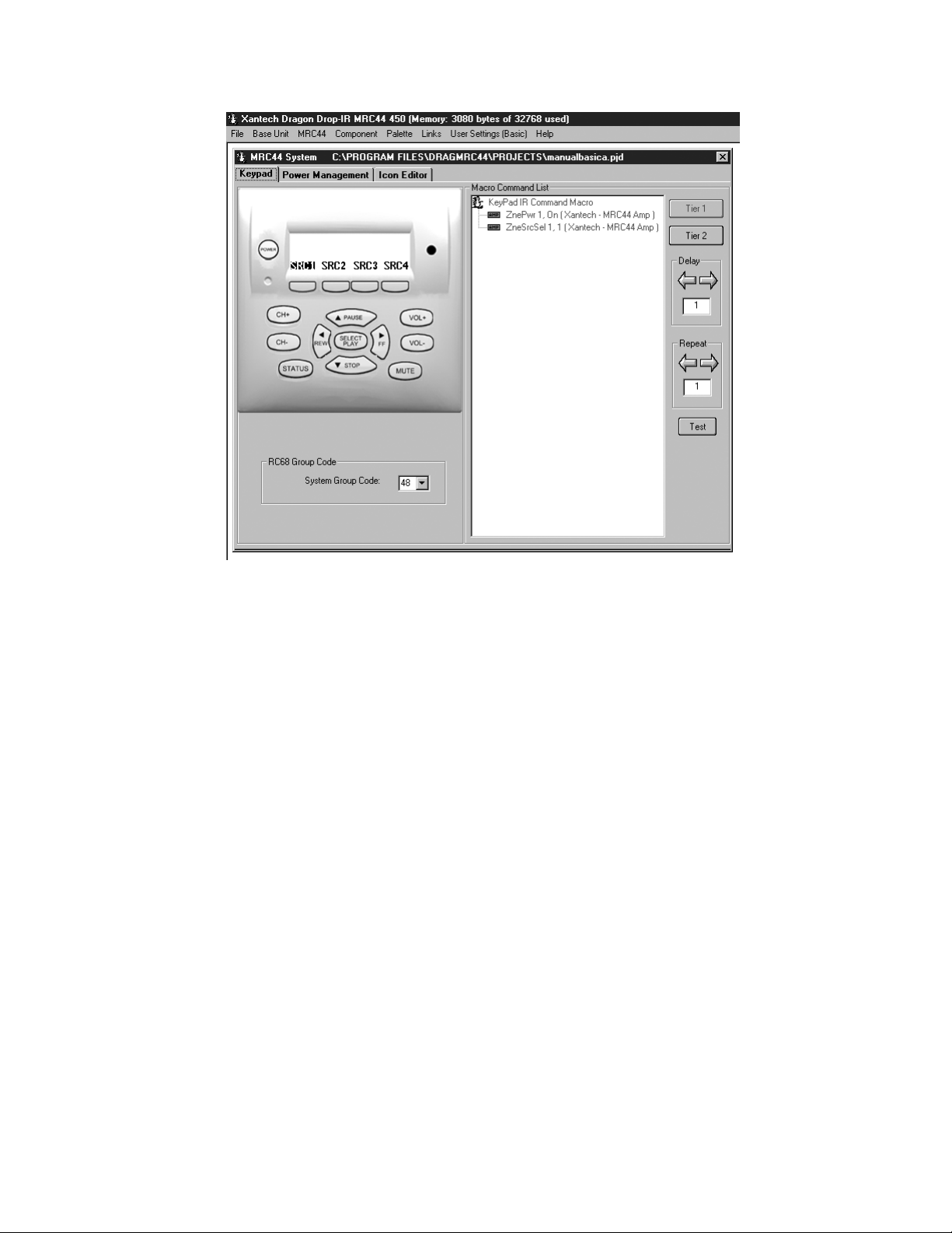
PROGRAMMING KEYPADS
(BASIC)
With Dragon open, from “FILE” select “NEW PROJECT” and give the project a name. Hit “ENTER” on the
keyboard or click “SAVE”. Click on “USER SETTINGS” in the Menu bar. Select “BASIC DRAGON.” Click on the
“BASE UNIT” Pull Down in the Menu bar and select “MRC44”.
The MRC44 “BASIC SYSTEM W INDOW” will appear (Figure 17) with a "virtual keypad", default source buttons
(SRC1, SRC2 etc.) along with tabs, which allow selection of Keypad, Power Management and Icon Editor. In
the menu bar, “USER SETTINGS” will indicate “(Basic)”.
NOTE: A project can be changed from Basic to Advanced or Expanded, but once changed cannot be changed
back to Basic. See Programming Keypads (Advanced/Expanded).
© 2002 Xantech Corporation
Page 27
Model MRC44 Page: 27
Figure 17 – DRAG450MRC Basic System Window
(ADVANCED)
With Dragon open, from “FILE” select “NEW PROJECT” and give the project a name. Hit “ENTER” on the
keyboard or click “SAVE”. Click on “USER SETTINGS” in the Menu bar. Select “ADVANCED DRAGON.” Click
on the “BASE UNIT” Pull Down in the Menu bar and select “MRC44”.
The MRC44 “ADVANCED SYSTEM WINDOW” will appear with a "virtual keypad", default source buttons
(SRC1, SRC2 etc.) buttons which allow selection of Zone (1-4), along with tabs, Sense Setup, Controller, Zone
Linking and Icon Editor. In the menu bar, “User Settings” will indicate “(Advanced)”.
NOTE: A project can be changed from Advanced to Expanded and back with only a change in the number of
Zones.
(EXPANDED)
With Dragon open, from “FILE” select “NEW PROJECT” and give the project a name. Hit “ENTER” on the
keyboard or click “SAVE”. Click on “USER SETTINGS” in the Menu bar. Select “ADVANCED DRAGON.” Click
on the “BASE UNIT” Pull Down in the Menu bar and select “MRC44”.
The MRC44 “ADVANCED SYSTEM WINDOW” will appear. Select the Controller tab. In the Expanded Options
box, select ‘EXPANDED’. A message…”Please wait” will appear for about 10 seconds. A "virtual keypad",
default source buttons (SRC1, SRC2 etc.) buttons which allow selection of Zone (1-8), along with tabs Sense
Setup, Controller, Zone Linking and Icon Editor. In the menu bar, “User Settings” will indicate “(Advanced)”.
© 2002 Xantech Corporation
Page 28

Page: 28 Model MRC44
Configuring Source Icons on MRC44 Keypad LCD
(BASIC/ADVANCED/EXPANDED)
Programming Source Icons
Figure 18 – MRC44 Keypad LCD Icon Generator
Icon Generator
The display on the MRC44 Keypad is configurable to graphically show the type of source that can be selected
at each input. The Icon Generator has a preprogrammed library of icons (bitmaps) that can be assigned to each
source input. The Icon Generator has several optional source icons pre-configured at the factory. They include
such components as CD, DVD, VCR etc. New Icons up to 4 characters in length can also be created in Dragon
for sources not found in the default library using the Icon Generator.
1. Double Click on the icon in the virtual keypad window. A text box will appear.
2. Type in the letters (up to four) for the source to be selected from that source button i.e. CD, DVD, VCR,
SAT, etc
3. Press enter on the keyboard
4. Repeat for all sources or…
2. Right click on the Source button to be labeled.
3. From the pop-up menu, Select “LOAD ICON”. A list of icon bitmaps will appear.
4. From the list, select the desired icon and click “OK” (or double-click the desired icon). The icon will appear
in the ‘virtual LCD’ on the keypad in the MRC44 System W indow. The source icon will appear in all zones
on the ‘virtual’ keypads.
5. Repeat for all sources.
6. From the main menu bar, select, “MRC44 KEYPADS ICON DOWNLOAD”.
7. A Dragon/MRC44 connection warning window will appear. Click ‘NEXT”. The icons will be transferred to the
MRC44. Click “FINISH” when transfer is completed.
8. If the zones are “OFF” the icons will appear as zones are turned “ON”. If zones are “ON” when icons are
transferred, The zone keypad will turn “OFF”. New icons will appear when zone is turned “ON”.
© 2002 Xantech Corporation
Page 29

Model MRC44 Page: 29
Creating New Icons
1. Click on the “ICON EDITOR” tab in the MRC44 System Window. The ‘Icon Editor’ window will appear.
2. Click “NEW”. This will clear the screen.
3. To type a new source name, using the PC keyboard, Select “TEXT”. A source name, or icon, up to four
characters in length can be created. (i.e. SAT2)
4. Click the “SAVE AS” icon.
5. In the ‘File Name’ box, type in the same letters used in the icon. (Anything can be entered, but using the
same letters/characters may be easier for associating files with icons).
6. Select the Keypad tab in the Project Window.
7. Right click on the Source button to be labeled.
8. From the pop-up menu, Select “LOAD ICON”. A list of icon bitmaps will appear, including new icons.
NOTE: Source icons will be copied to all keypads in a project automatically in Dragon weather programmed
in basic, advanced or expanded mode.
Selecting Palettes
a) From the Palette menu, click Select “IR COMMAND PALETTE”. (F4)
A list of palettes file names appears to the right with Select Palette in the title bar.
b) Scroll the list (if necessary) and click on the filename of each palette you need for your system (e.g.
pioneercd.pal, rcadss.pal, etc).
As you click on each file name, the palettes will appear side-by-side, left to right, with the filename in
each title bar.
NOTE 1: The various palettes and window boxes can be moved and sized (except the virtual keypads)
for ease of use.
NOTE 2: Each palette can be edited by clicking the Edit Palette bar or closed with the X button in the
title bar.
Placing Commands On The Virtual Keypad
(BASIC)
a) Select “KEYPAD” in the MRC44 System Window.
b) Click the desired Source button on the MRC44 Keypad.
c) Click a Function button, click the applicable command from the palette for that component function and
then the code name (function/brand/component) for that button will appear in the Macro Command List
on the MRC44 Programming Module.
d) To remove a command right-click on the code in the command list, it will disappear, showing that it has
been erased.
e) To add additional commands to the same button, just repeat steps “b” to “c”. (See: “Editing
Sequences”)
f) Repeat for all buttons, all sources.
g) In Basic mode all commands and sequences will be copied to all zones automatically
(ADVANCED/EXPANDED)
a) Select the Zone tab in the MRC44 System Window.
b) In the “SELECT ZONE’ box, select the zone to be programmed.
c) Follow steps ‘b’ through ‘f’ above.
NOTE 1: If a particular command or sequence is to be copied to all 4 sources on a Keypad, right click that
button and click “PUNCH” from the pop-up menu. That buttons command or sequence will now be
programmed for that button on all four sources for that Keypad.
NOTE 2: If all Keypad functions in all zones are identical, right click on any button on the Keypad to be copied,
and click “PUNCH ALL” from the pop-up menu. All Keypads will now be completely and identically
programmed.
Programming Sequences
All programmable buttons on the MRC44 Keypad can be programmed to send IR sequences of up to 40
commands.
1. Click the button to be programmed.
2. Open all palettes to be used in the sequence.
3. In the palettes, click on the commands in the order of the sequence to be sent.
© 2002 Xantech Corporation
Page 30

Page: 30 Model MRC44
Editing Sequences
1. The Command List can be edited by dragging and dropping any command on the list to any position on the
list. Left click and drag the command to be moved. As you drag upward and you want the command
between two existing commands, drop it on the lower one. As you drag downward, drop it on the upper one.
2. You can delete any command on the list by Right Clicking on the command.
Timed Delays
1. Timed delays can be placed in a sequence. Click the left < and right > arrows under “DELAY” in the
Command List window for the number of seconds you want (i.e. 2 = 2 seconds).
2. Double Click within the “Delay” outline. This will place the delay at the end of the Command List and the
delay time appears on the list (e.g., Delay 2 Sec).
3. Left Click and Drag the “Delay 2 Sec” line and drop it between any two commands you have placed on the
Command List.
Repeat Commands
1. To repeat an IR command for any reason, just use the arrows to set the number of times to repeat a code
and Double Click in the “REPEAT” outline. This will place a “cycle” symbol and the words “Repeat 3 Times”
(if 3 is selected) at the bottom of the Command List.
2. Left Click on the “Repeat 3 Times” line and place it directly ahead of the code to be repeated.
Push & Hold (Tiered) Commands
The commands thus far have been placed, by default, on TIER 1 (or the first level) of the button. If you wish to
add a command(s) to the second Tier,
1. Click on “TIER 2” in the Command List window. The Tier 1 commands disappear.
2. Repeat all of the same steps as described for programming Tier 1 Commands.
Getting Source Commands From The Internet
Xantech.com
There are some IR commands that can be difficult to learn in Dragon. Xantech edits and posts some of these
commands at xantech.com under Products/IR Code Libraries. (See website for listings and download
instructions.) A direct link to xantech.com can be found in the “Links” option in the Dragon menu bar.
Remote Central.com
There is a second option for on line IR codes. remotecentral.com provides an almost unlimited resource of IR
commands. The code files at Remote Central are not directly compatible with Dragon Drop-IR and therefore
need to be converted for use with Xantech software.
1. Click “LINKS” in DRAG450MRC.
2. Click on Remote Central Website. Your browser will open and take you to Remote Central.com.
3. Click Files in Remote Central.
4. Click Philips Pronto & Pronto Pro.
5. Scroll and click on desired brand under "Component Configurations" (CCF files).
6. Click on component type (CD players, VCR's, etc.).
7. From the list find a Model Number the same as your model or one similar to it. (Even model numbers
considerably different than yours will usually have commands that work).
8. Click on DOWNLOAD (this may take a few seconds), then select Save it to disk, then OK.
9. In the W indows ‘Save As…’ pop-up, Open the CCF folder within the DragMRC44\CCF folder (if not already
open). Click Save.
10. In DRAGMRC44, click Import CCF from the File menu.
11. Find the ccf folder in which you saved the file and click on file name.
NOTE: At this point, prior to opening it, you may wish to change the file name (e.g., RCA-DSS, etc.) for
easier recognition later. You may wish to do this in step 13 as well.
12. Click Open. This unzips the file and DRAGMRC44 automatically places it in a folder within the CCF folder.
13. Click on file name, then on Open. At this point, the CCF file is converted to a Dragon format.
14. On pop-up (CCF Importer), type in Brand Name and Component Name (e.g., RCA and DSS).
15. Double click on desired component type on list of converted files on left side of pop-up (e.g., DSS.cnv). An
asterisk (*) will appear just to the left. Click Import.
© 2002 Xantech Corporation
Page 31

Model MRC44 Page: 31
16. Click OK for addition to Brand List (if shown) and OK for addition (or merge) to a .bci file.
This completes the file import to the Brand and .bci files in DRAGMRC44.
17. At this point, or at any later date, you can choose additional component types from the CCF file (e.g., DVD,
etc., if listed) by using the CCF Importer again. Simply click Import CCF from the File menu, double click on
desired folder and repeat steps 13 to 16 as necessary.
SYSTEM SET-UP PROCEDURES
Zone/Keypad Set-Up
(BASIC)
Assumes use of system defaults other than source icons and IR programming.
(ADVANCED/EXPANDED)
Within the MRC44 System, each zone can be customized for a number of performance options. For most
installations, the factory default settings will be used and will require no additional configuration.
Name Of Zone
(ADVANCED/EXPANDED)
Each zone can be given a name (i.e. Living Room, Bedroom etc.) to more easily plan and program the keypads
and zones in a MRC44 system.
1. To change the name of a zone, Click the ‘OPTIONS” button.
2. In the “Select Zone” box, select the number of zone to be named.
3. Select the text in the “NAME OF ZONE” box and type in the new name.
4. Selecting another zone or clicking the “CLOSE” button will save the Zone Name/s.
RC68 Code Group
(BASIC)
In basic mode, the code group can only be set for the entire system.
(ADVANCED/EXPANDED)
Each zone of the MRC44 can be set to it’s own individual Code Group. This may be useful when the system
requirements so dictate. (i.e. The system requirement calls for having zone-specific remote controls). The Code
Group Number assigned and preset at the factory for each zone of the MRC44 is 48. Since other Xantech IR
controlled models are assigned and preset at the factory to different Code Groups, special care should be taken
when changing code groups to avoid accidentally changing another products code group number or having the
wrong product respond to an IR code intended for a different model.
NOTE 1: When using programmable remotes, it will be useful to have an RC68+ to generate the IR codes for
programming.
NOTE 2: See RC68+ instructions for additional information on Code Groups.
Keypad LCD Display Contrast
(ADVANCED/EXPANDED)
Adjusts the Contrast of the LCD Display on the Keypad. Adjust to preference and or to compensate for varying
room ambient light conditions.
Number Of Keypads In Zone
(BASIC/ADVANCED/EXPANDED)
A zone may have one, two or no keypads. On power-up, the MRC44 Controller automatically polls the system
and identifies how many keypads are connected to a given zone.
Repeat “SYSTEM SET-UP PROCEDURES” as needed for all zones.
© 2002 Xantech Corporation
Page 32

Page: 32 Model MRC44
PROGRAMMING THE MRC44 CONTROLLER/AMPLIFIER
Figure 19 - MRC44 System Window Sense Input Tab
Automatic Source Power Management (Figure 19)
(BASIC/ADVANCED/EXPANDED)
With the ability to turn the system ON and OFF from more than one location, The MRC44 Controller needs to
know when the different sources are ON or OFF and be able to know when to send or not send power
commands to keep the sources in sync with the system. The MRC44 Controller features two sensing methods.
One is video sensing. All four source video inputs are set to detect a video input signal (NTSC and PAL sync).
When detected, the MRC44 controller knows when to send or not send power commands to keep components
in sync with system activity. The other method is current sensing. Current sensing functions the same way, but
detects the difference in current drawn by the component when its either ON or OFF.
Sense Inputs (Factory default - “DISABLED”)
(BASIC/ADVANCED/EXPANDED)
Specific IR commands can be associated with the ON and OFF states of a sensed device and sent
automatically to the source emitter when the system is turned ON or OFF. The MRC44 Controller will also poll
the sensors every 30 seconds to maintain proper sync of the source components to the system. If a particular
source component automatically turns itself OFF after a certain time of inactivity, or if a component is
accidentally turned OFF, the system will sense a source OFF condition with a system ON condition and
automatically turn the source back ON, keeping all sources ready for use at any time.
When any zone on the MRC44 is turned ON, all sources with IR codes associated with sensed conditions will
be turned ON.
10 seconds after the last zone on the MRC44 is turned OFF, provided no new activity occurs, all sources with
IR codes associated with sensed conditions will be turned OFF.
© 2002 Xantech Corporation
Page 33

Model MRC44 Page: 33
PROGRAMMING POWER MANAGEMENT AND SENSE TRIGGER CODES
(BASIC)
In the Basic mode Video and Current Sensing can only be used for power management of common source
components.
(ADVANCED/EXPANDED)
In Advanced or Expanded modes, the Video and Sense inputs can be used for either power management of
source components or as sense triggers to initiate IR codes or Internal Amplifier Commands.
NOTE 1: A video or sense input can only be used for either power management or sense trigger on from a
single source.
NOTE 2: IR commands issued for power management or sense trigger will be output from the corresponding
source IR and common IR outputs.
Video Sensing (Power Management)
VIDEO SENSING is incorporated internally on each of the source video input jacks. NTSC sync and PAL
signals are detected indicating the source component is ON. The absence of these signals indicates an OFF
condition.
Example: Video Sensing on a DVD Player on Source Input 1.
1. Select “POWER MANAGEMENT” tab in MRC44 Basic System Window
ADVANCED/EXPANDED: Select “SENSE SETUP” tab.
3. Select: Source 1 Video Sense.
4. Open the Palette for the DVD Player from the Palette Menu.
5. In the Macro Command List box, Select the “POWER ON” button.
6. Click on the POW ER command in the open DVD Palette if using a power toggle command. (Same
command for ON and OFF). If separate ON/OFF commands are available, click the POWER ON command.
7. In the Macro Command List box, Select the “POWER OFF” button.
8. Click on the POW ER command in the open DVD Palette if using a power toggle command. (Same
command for ON and OFF). If separate ON/OFF commands are available, click the POWER OFF
command.
9. Repeat for all sources that will use video sensing.
Video Sensing (Sense Trigger)
(ADVANCED/EXPANDED)
The Video inputs can be used as sense triggers. If IR codes or Internal Amplifier Commands are associated
with a video input in the Sense Trigger mode, the associated codes or commands will be issued when the
sensed state is detected. e.g. When a DVD player or TV is turned ON, have the video signal trigger an IR code
to be issued via the common IR output to a Xantech IRS232 that could then send ASCII commands to a
lighting system to set room lighting.
Current Sensing (Power Management)
Sense Inputs
The SENSE input is used to sense the POWER ON or POWER OFF condition of a source. A current sensing
module (Xantech Part # CSM1) must be used for this application. Adjust the threshold sensitivity on the CSM1
as described in “Sense Input Connections” Page 16.
IR programming same as ‘Video Sensing’ above, just Select “Current Sense” in Step 2.
NOTE: Be sure to properly adjust the Threshold on the CSM1.
Current sensing (Sense Trigger)
(ADVANCED/EXPANDED)
The Sense inputs can be used as sense triggers. If IR codes or internal amplifier commands are associated
with a CSM1 or switch closure in the sense trigger mode, the associated codes or commands will be issued
when the sensed state is detected. e.g. A modified doorbell circuit could be used to mute a zone or zones using
Internal Amplifier Commands when triggered by the sensed doorbell switch closure.
© 2002 Xantech Corporation
Page 34

Page: 34 Model MRC44
Polarity of Sense Input
TIP: +12VDC
RING: Input (+12VDC)
SLEVE: Ground
When using a dry contact closure to activate a Current Sense Input Trigger, the switch should be between TIP
and RING.
When using an external voltage, (12 volt control out from switched outlet, etc.) the switch should be between
SLEVE and RING.
Current Sense De-Bounce Settings
“De-Bounce” is the amount of time switches and relays need to stabilize. The factory default of ‘2’ should be
tried first. For a faster switch, try the ‘1’ setting. For slower switches change as needed to allow the controller to
sense the switch or relay condition.
Transferring The Project
(BASIC)
The project can now be transferred to the MRC44 if it is being set up in the Basic mode. For Advanced and
Expanded systems, continue to next section. See page 41 “Transferring a Project” for instructions.
ADVANCED/EXPANDED PROGRAMMING
CONTROLLER OPTIONS PROGRAMMING
Figure 20 - MRC44 System Window Controller Tab (Advanced/Not Expanded)
Whole House Mode (Factory default: “ENABLED”)
This mode allows any zone to be able to select and control any source at any time.
© 2002 Xantech Corporation
Page 35

Model MRC44 Page: 35
Priority Lockout Mode (Factory default: “DISABLED”)
This mode is the opposite of “Whole House”. That is, when one is ENABLED, the other is DISABLED. When
ENABLED, if Zone 1 selects a source, Zone 1 will maintain exclusive control over that source until Zone 1
either selects another source or is turned OFF. Zones 2-4 can monitor the source, but cannot control that
source until released by Zone 1. Once Zone 1 has released the source, if the source is re-selected by one of
Zones 2-4, that zone will take control and will then also have priority.
IR Routing (Factory default: “ENABLED”)
This mode allows selective control of multiple same-brand same-model components such as multiple DVD
players or Satellite receivers. When “ROUTING ENABLE” is selected, IR commands are directed only to the
specific emitter output for the source selected in a zone, and not to the other source emitter outputs. When
“ROUTING DISABLE” is selected, IR commands are directed to all emitter outputs. The COMMON emitter
output will always output all IR commands.
Backlight Control (Factory default: 6 seconds)
This setting adjusts the duration that the Keypad LCD and Buttons will remain lit after a keypad button press.
Backlighting is variable from ‘always off’ to ‘always on’ or set to time out after 1 to 10 seconds in one second
increments. This setting will set the backlighting for ALL keypads in the system. IR codes generated by remote
controls do not activate backlighting.
1. Click “ALWAYS ON” to backlight a zone’s keypad(s) for as long as the zone is ON. Backlight turns off
when the zone is turned OFF. Useful in dark rooms.
2. Click “ALWAYS OFF” keypad(s) backlight will never turn on. Useful in rooms that are always brightly lit.
3. Click “TIMED” and use ‘Timed Backlight Control’ Pulldown Menu to set backlight duration from 1-10
seconds.
Monitor Lockout Mode (Factory default: “DISABLED”)
This mode can only be used if ‘Priority Lockout’ is selected. Checking the corresponding boxes prevents
sources from being monitored or controlled in specific zones. Example: If adult content is not to go to the
children’s areas this can be set at the time of system installation.
1. Select “PRIORITY LOCKOUT MODE” The Monitor Lockout boxes will be activated.
2. By Zone, click in the box of any Source that is not to be monitored in that zone.
Dynamic Monitor Lockout (Factory default: “DISABLED”)
This mode allows monitor lockout ‘on the fly’. There may be times when a source is generating program
material that can be made available to all zones/users. At other times this same source may be putting out
material that is not suitable for some zones/users. When the “ADMINISTRATOR” box is checked for a given
zone, for example, Zone 1, a special keypad command can block the audio and video for a given source from
being monitored by Zones 2-4 (Zones 2-8 in Expanded mode). When the special keypad command is issued a
second time, in Zone 1, that source is released and can then be selected and monitored by Zones 2-4 (Zones
2-8 in Expanded mode). That source remains under ‘priority control’ of Zone 1, until Zone 1 selects another
source or turns OFF.
1. Select “PRIORITY LOCKOUT MODE” The Monitor Lockout boxes will be activated.
2. Click the “ADMINISTRATOR” box for any zone that is to have ‘Dynamic Monitor Lockout’ ability.
3. After the project has been transferred to the MRC44 Controller, on a keypad in a zone with ‘Administrator’
control, simultaneously press the ”STATUS” and “SOURCE” buttons for the device to be ‘locked out’. If any
zone has that same source selected, the audio will mute and the video will go blank. A message: “Monitor
Locked” will appear on the keypad(s) in those zones.
4. To unlock, from the same zone with ‘Administrator’ control, simultaneously press ”STATUS” and “SOURCE”
again. If any zone has that same source selected, the message “Monitor Unlocked” will appear, however,
video and audio will not be routed to that zone until a source select button is pressed. A message: “Monitor
Unlocked” will appear on the keypad(s) in those zones. The ‘Administrator’ zone will retain priority until that
zone selects another source or turns OFF.
IR Output Intensity Settings
Emitter outputs 3, 4 and common have adjustable output levels to compensate for the varying IR sensitivities in
different branded products. The Low setting is equivalent to the emitter out on a 789-44 Connecting block (470
© 2002 Xantech Corporation
Page 36
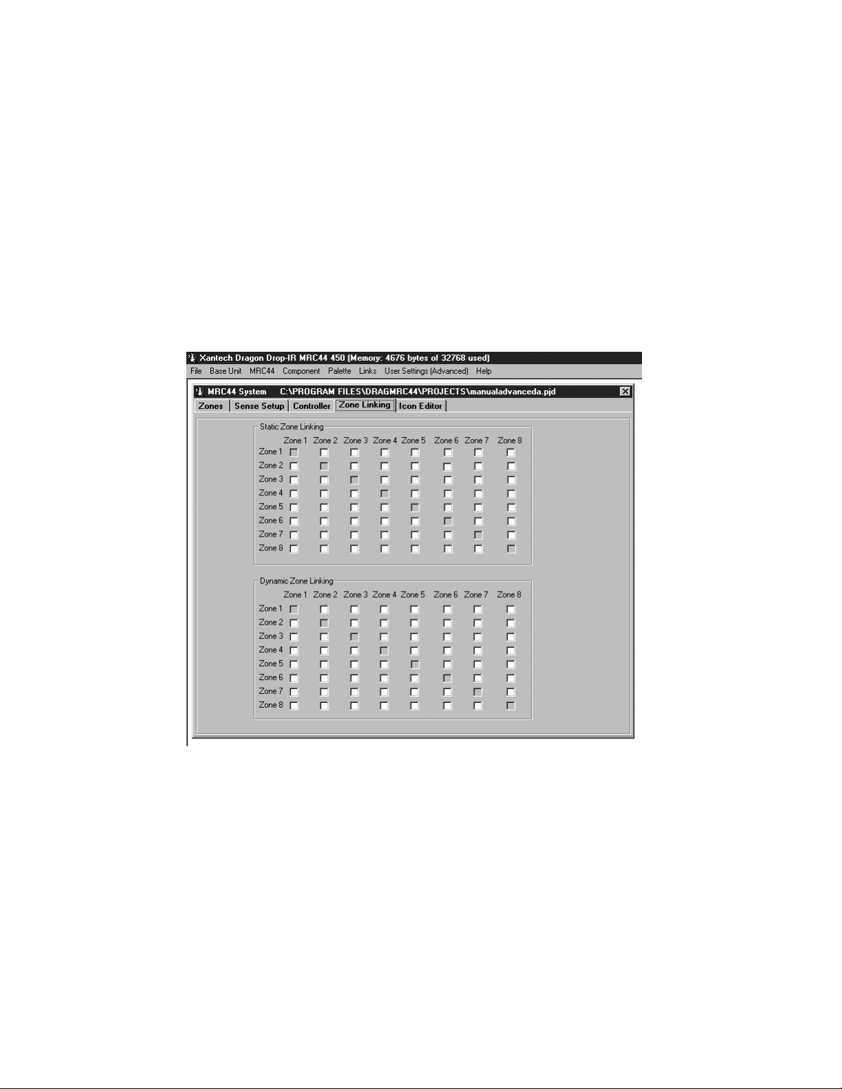
Page: 36 Model MRC44
ohm resistor.) The Low output should normally be used. The Medium Setting is close to the High Power Mode
emitter out on a 791-44 Amplified Connecting Block (120ohm resistor.) The Medium output should be used with
components with weak IR signals or when the emitter wire needs to be extended if a source component is
some distance from the Controller. The High Setting can be used when driving a 789-44 Connecting Block to
drive multiple emitters from the Common IR out. Source 1 and 2 emitter output levels are equiv alent to the
emitter out on a 789-44 Connecting Block (470 ohm resistor.)
Expanded Options
For systems using a single controller (four zones or less) and that will use Advanced Programming features, the
NOT EXPANDED mode should be selected. For any system using two controllers, (five to eight zones) the
Expanded mode must be selected. When changing to the Expanded mode a “Please Wait” message will
appear on screen. Dragon Drop-IR will take about ten seconds (depending on computer speed) to update. The
Zones, Controller and Zone Linking tabs will now open the options for eight zone programming and
configuration.
ZONE LINKING
Figure 21 - MRC44 System Window Zone Linking Tab (Advanced/Expanded)
Static Zone Link Mode (Factory default: “DISABLED”)
This mode allows any combination of zones to behave as a single zone with regard to power (ON/OFF) and
source selection, to create multi-room zones. If Zones 1 and 2 are linked, when either is turned ON or OFF,
both will turn ON or OFF. Source selections and source content will be identical in both zones. Volume and
mute can still be controlled separately in each of the linked zones.
Example: Link Zones 1 and 2.
1. In the ‘Static Zone Link Mode’ box under Zone 1, click in the box “ZONE 2”. A check mark will appear in
both the Zone1/Zone 2 box and the Zone 2/Zone 1 box to show that these two zones are now tied together.
2. After the project has been transferred to the MRC44 Controller, all linked zones will have a small ‘L’ in the
upper right corner of the LCD on the keypad(s) in those zones. Simultaneously pressing the “STATUS” and
“CH+” buttons will change the keypad display and indicate linked zones with a reverse highlight of the
© 2002 Xantech Corporation
Page 37

Model MRC44 Page: 37
linked zone numbers. (i.e. The display in Zone 1 would show: “LINK SESSION” Z2). The display will ‘time
out’ and return to the normal screen after 10 seconds.
Dynamic Zone Link Mode (Factory default: “DISABLED”)
This mode allows zone linking ‘on the fly’. There may be times when it may be desirable to link multiple zones,
that might not be the normally desired system configuration. (i.e. linking the living room and dining room for a
dinner party.) Authorizing zones for ‘Dynamic Zone Linking’ is the same as programming ‘Static Zone Linking’
Step 1, above. The difference is, once a zone has been authorized to link with another zone(s), the actual
linking is implemented from Keypad button presses and can be reversed in the same way.
Example: Dynamically Link and unlink Zones 1 and 2.
1. In the ‘Dynamic Zone Link Mode’ box under Zone 1, click in the box “ZONE 2”. A check mark will appear in
both the Zone1/Zone 2 box and the Zone 2/Zone 1 box to show that these two zones can now be tied
together.
2. TO LINK: After the project has been transferred to the MRC44 Controller, from the Zone 1 Keypad,
simultaneously press “STATUS” and “CH+”. The ‘Link Session’ window will appear on the Keypad LCD.
3. Press the “Z2” button (Source 2 button). ‘Z2’ will be highlighted to indicate it is now linked to Zone 1. The
Keypad status LEDs will show ‘busy’ (rapid amber flash) for 10 seconds after the last button press, then
‘time out’ and return to normal use mode (LED /green, LCD/normal display). A small ‘L’ will appear in the
upper right corner of the displays in Zones 1 and 2. Zones 1 and 2 will now be linked for ON/OFF and
Source. Volume and mute will be independent.
4. TO UNLINK: From the Zone 1 Keypad, simultaneously press “STATUS” and “CH+”. The ‘Link Session’
window will appear on the keypad LCD.
5. Press the “Z2” button (Source 2 button). ‘Z2’ will no longer be highlighted. The keypad status LEDs will
show ‘busy’ (rapid amber flash) for 10 seconds after the last button press, then ‘time out’ and return to
normal use mode (LED /green, LCD/normal display). The small ‘L’ will no longer appear in the upper right
corner of the displays in Zones 1 and 2. The zones will now be independent for all functions.
NOTE 1: When programming Link Mode in Dragon only Static or Dynamic linking can be selected for
linking any group of zones.
NOTE 2: With proper configuration, any Zone/s can be linked to any other Zone/s. In order to link any of
Zones 1-4 to any of Zones 5-8, the system must be programmed in Expanded Mode and connected at the
COM ports with a DB9 nul modem cable.
Firmware Upgrade Options
The MRC44 has been designed to be “Future Proof”. As product feature improvements are developed, new
operating systems will be available. Periodically monitor Xantech.com for upgrades.
1. Open the Dragon Drop-IR™ MRC44 software. Make sure you have an Internet connection as well as
having the MRC44 connected to your computer’s COM port.
2. With the MRC44 powered ON, press the LEVEL RESET button on the back of the unit two times within a
second.
3. Select the Links menu item and then select Xantech Firmware Upgrade Page. This will connect to the
Xantech web site and load the Xantech Firmware Updates page in your browser. If you do not have an
active Internet connection, you will not be able to successfully complete this step or proceed.
4. Locate the most recent MRC44 firmware update file within the list - the one with the highest version number
(entries are sorted with the newest entries at the top of the list and the oldest at the bottom). Click on the
desired filename link to begin the download process.
5. A window will popup asking “Do you want to open the file or save it to your computer?” Select Save.
6. A Save As window will then open. Navigate to the Firmware folder within the DragMRC44 folder (usually
located within the Program Files folder of your local hard disk). Click on Save.
7. Once the download is complete, click on Close to close the download window. You can also close your
browser.
8. Now, return to the Dragon Drop-IR MRC44 software, open a project and then select the MRC44 Pulldown
from the menu bar. Select Warm Firmware Upgrade. Then click on Start in the Firmware Upgrade
section.
9. A popup window titled Select Firmware Upgrade File will open allowing you to select the firmware file to
be loaded into the MRC44 Controller/Amplifier. You should see the file that was just downloaded in step 6
above. Double-click on that filename to begin the update process.
© 2002 Xantech Corporation
Page 38

Page: 38 Model MRC44
10. After the firmware transfer is completed, select the Base unit menu item and then select Who am I? It
should now display the correct three-digit firmware version that you just loaded into the MRC44 unit. If this
is true, the new firmware has been successfully installed and is ready for use.
RC68+ IR CODE TRIGGERED SEQUENCER
The MRC44 Controller/Amplifier can generate IR code sequences triggered by single RC68+ commands. This
feature can be useful in eliminating partial sequence execution from hand-held controllers and allowing a wider
range of programmable remotes that can be used with MRC44 that don’t allow sequence programming.
When the MRC44 Controller/Amplifier receives certain RC68+ commands, via the Keypad IR sensor or an
external IR sensor, the system will output a sequence of IR commands. The sequence can be any combination
of Source Commands, RC68+ Commands and Internal Amplifier Commands. The IR codes in the sequence will
be output to Source components via the appropriate emitter output and to the common IR output for control of
other devices and systems. Any Internal Amplifier Commands will be processed by the MRC44
Controller/Amplifier internally.
In the MRC44 System Window, Click on RC68 in the lower right hand corner of the MRC44 System Window
and the image shown in Figure 22 will appear.
Figure 22 – RC68 IR Command Macro Window
Programming RC68+ Triggered Sequences
Example: Turn on a zone, select a source and play a CD player from a single RC68+ command received from a
hand-held programmable remote.
1. Open the MRC44 System Window to the RC68 IR Command Macro Window as shown in Figure 22.
2. Open the palettes for the devices to be controlled in the sequence.
3. Select the RC68+ Sequence Trigger Command. (e.g. Click on button ‘80’. It will be outlined in blue.)
NOTE: The shaded buttons are not available for this application. They are reserved for system set-up
modes. See “Fine Tuning” Page 42.
© 2002 Xantech Corporation
Page 39

Model MRC44 Page: 39
4. From the Internal Amplifier Command Window Select “ZONE TOGGLE POWER COMMAND” and set to
the appropriate zone number. That command will appear in the Command List.
5. From the Amplifier Command Generator select “ZONE SOURCE SELECT COMMAND” and set to the
appropriate zone and source number. That command will now appear in the Command List.
6. From the CD player palette, select the “PLAY” command. It will now appear in the command list.
7. It may be necessary to insert a delay into the sequence between the input and play commands. Using the
right and left arrows, set “DELAY” to the desired length. Left click and drag the delay box, into the command
list between “INPUT” and “PLAY”. It will appear on the command list.
8. The sequence can be tested with the PC connected to the MRC44 com port by selecting the RC68
command and clicking on “TEST”.
9. Make any adjustments to the sequence as needed.
10. Once the project has been transferred to the MRC44, any time the MRC44 Controller ‘sees’ the ‘80’
command, this sequence will be initiated. By teaching the ‘80’ command to a hand held remote, it is now
only necessary to send the one IR code and have the sequence generated by the MRC44.
PROGRAMMING INTERNAL AMPLIFIER COMMANDS
In the MRC44 System Window Menu, click on Palette, and select “MRC44 AMPLIFIER COMMAND
GENERATOR” (F6), a special palette of MRC44 Internal Commands will appear, as shown in Figure 23.
Figure 23 – Internal Amplifier Command Window
This special Palette contains the commands used by the MRC44 Controller/Amplifier for default functions and
set-up modes.
NOTE: THESE COMMANDS ARE ALREADY PROGRAMMED INTO THE MRC44 AT THE FACTORY. They
are made available for use in special programming such as having a particular zone default to a particular
source when that zone is turned ON. Though RC68+ commands can be used to control the MRC44 via remote
control, RC68+ commands will not be recognized by the MRC44 Controller’s microprocessor if generated by a
MRC44 Keypad. An RC68+ command generated by a keypad will pass directly through to the emitter outputs.
To control the MRC44 from a keypad it is necessary to use these special internal amplifier commands.
© 2002 Xantech Corporation
Page 40

Page: 40 Model MRC44
1. In the MRC44 System Window Menu, click on Palette, and select “MRC44 Amplifier Command Generator”
(F6).
2. From the MRC44 System Window, select the Zone to be programmed. (e.g. Zone 1)
3. Click the button to be programmed. (e.g. “Power”)
4. Select the command to be used (e.g. “Zone Source Select Command) from the pull-down list in the
Amplifier Internal Command Setup window.
5. Two Parameter boxes will appear as shown in Figure 23, to set the action of the command. (e.g. Zone 1
and Source 1).
6. A table of MRC44 Controller/Amplifier commands is shown in Table 2 below with the associated controls.
7. Click “ACCEPT” when the Internal Amplifier Command is set to the desired state.
8. The command will automatically be placed in the command list of the Zone/Button selected. (In this
example when the Zone 1 “POWER” button is pressed, and the zone is OFF, the zone will turn ON, Source
1 will automatically be selected and by adding a “PLAY” command for a CD player to the sequence, Zone 1
will always default to CD when turned ON. Pressing the “POW ER” button again will turn the zone “OFF”.
9. Repeat for all zones and commands as required.
(EXPANDED)
In the Expanded mode, Internal Amplifier Commands can only be programmed to ‘talk’ to the zones within
either the Primary or Secondary Controllers. Internal Amplifier Commands are not communicated from one
controller to the other. The one exception is the “Turn Off All Zones Command” which will turn all zones OFF.
Command Name Command List Name Parameter 1 Parameter 2
Zone Power Command "MRC44 ZnePwr" Zone (1-4) (5-8) PwrState (On, Off)
Zone Toggle Power Command "MRC44 TogZnePwr" Zone (1-4) (5-8) N/A
Zone Volume Level Command "MRC44 ZneVol" Zone (1-4) (5-8) VolLevel (0 – 63)
Zone Volume Step Up Command "MRC44 ZneVol+" Zone (1-4) (5-8) N/A
Zone Volume Step Down Command "MRC44 ZneVol-" Zone (1-4) (5-8) N/A
Zone Balance Level Command "MRC44 ZneBal" Zone (1-4) (5-8) BalLevel (-15-15)
Zone Balance Step Up Command "MRC44 ZneBal+" Zone (1-4) (5-8) N/A
Zone Balance Step Down Command "MRC44 ZneBal-" Zone (1-4) (5-8) N/A
Zone Treble Level Command "MRC44 ZneTreb" Zone (1-4) (5-8) TrebLevel (-14dB-14dB)
Zone Treble Step Up Command "MRC44 ZneTreb+" Zone (1-4) (5-8) N/A
Zone Treble Step Down Command "MRC44 ZneTreb-" Zone (1-4) (5-8) N/A
Zone Bass Level Command "MRC44 ZneBass" Zone (1-4) (5-8) BassLevel (-14dB-14dB)
Zone Bass Step Up Command "MRC44 ZneBass+" Zone (1-4) (5-8) N/A
Zone Bass Step Down Command "MRC44 ZneBass-" Zone (1-4) (5-8) N/A
Zone Source Select Command "MRC44 ZneSrcSel" Zone (1-4) (5-8) Source (1-4)
Zone Mute State Command "MRC44 ZneMute" Zone (1-4) (5-8) MuteState (On, Off)
Zone Mute Toggle Command "MRC44 ZneTogMute" Zone (1-4) (5-8) N/A
Zone Set Control Status Command "MRC44 ZneCtlStat" Zone (1-4) (5-8) CtrlState (On, Off)
Zone Restore Balance Command "MRC44 ZneResBal" Zone (1-4) (5-8) N/A
Zone Restore Treble Command "MRC44 ZneRestTreb" Zone (1-4) (5-8) N/A
Zone Restore Bass Command "MRC44 ZneRestBass" Zone (1-4) (5-8) N/A
Zone Start Z Adjust Command "MRC44 ZneStrtZAdj" Zone (1-4) (5-8) N/A
Zone Set Max V Command "MRC44 ZneMaxV" Zone (1-4) (5-8) N/A
Zone Adjust Done Command "MRC44 ZneAdjDone" Zone (1-4) (5-8) N/A
Zone Start Trim Adjust Command "MRC44 ZneStrtTrim" Zone (1-4) (5-8) N/A
Turn Off All Zones Command “MRC44 ZneAllOff” N/A N/A
Table 2 – Internal Amplifier Commands
© 2002 Xantech Corporation
Page 41

Model MRC44 Page: 41
TRANSFERRING A PROJECT TO THE MRC44
(BASIC/ADVANCED)
When all programming of the virtual keypad has been completed and all IR commands tested, to confirm
operation, the project can be transferred to the MRC44.
Proceed as follows:
1. Be sure the MRC44 Controller and the PC are connected via the COM port on the back of the MRC44, that
power is applied to the MRC44, the MRC44 is connected to all sources and Keypads, and the MRC44 is
operating properly (see Out-of-the-Box in previous chapters).
2. Click Base Unit Transfer (Ctrl+B) from the File menu.
3. A Project Down Load window appears with the statement "Be Sure Dragon is Connected to MRC44…",
Click “NEXT”
4. A “Preparing Data for Download …” window appears and then changes into the “Please wait, Downloading”
window. A transfer status bar shows transmission of data.
5. When “Download Completed Successfully” appears, click “FINISH”.
6. MRC44 System should now be fully functional.
(EXPANDED)
1. Connect PC to the COM port on the PRIMARY MRC44 Controller.
2. Click Base Unit Transfer (Ctrl+B) from the File menu.
3. A Project Down Load window appears with the statement "Make Sure Dragon is Connected to MRC44
PRIMARY unit (zones 1-4)…", Click “NEXT”
4. A “Preparing Data for Download …” window appears and then changes into the “Please wait, Downloading”
window. A transfer status bar shows transmission of data.
5. A Project Down Load window appears with the statement "Make Sure Dragon is Connected to MRC44
SECONDARY unit (zones 5-8)…", Connect PC to the COM port on the Secondary Controller. Click “NEXT”
6. A “Preparing Data for Download …” window appears and then changes into the “Please wait, Downloading”
window. A transfer status bar shows transmission of data.
7. When “Download Completed Successfully” appears, click “FINISH”.
8. Connect the com ports on the two MRC44 Controllers using a male to male DB9 null cable or male to male
DB9 cable with a null modem.
9. Cycle power on both units for changes to take effect.
10. Expanded MRC44 System should now be fully functional.
UPLOADING MRC44 PROJECTS
Though other versions of Dragon Drop-IR allow ‘Uploading’ previously programmed projects, due to the
complexity of the data involved, MRC44 does not incorporate this function.
SAVING AND BACKING-UP FILES
Automatic Save
When working on a project in DRAG450MRC, it is automatically saved on a continuous basis, It is OK to quit a
project at any time and come back to it for further work by simply clicking on Open Project (Ctrl+O) from the File
menu and double clicking the filename in the list.
Save Project As
To create a variation of a project without having to reprogram everything from scratch, i.e. Change “Jones”
project to “Smith” project:
1. Click “SAVE PROJECT AS” Ctrl+S from the File menu.
2. SINGLE CLICK on the project file name to ‘Save As’.
3. Type in the new Project File Name (e.g. Smith) and click OK.
4. If there are no changes to the system (type of sources, brand of sources, zone configuration etc.) transfer
the project. If there are any changes to be made, modify the new project and then transfer to the MRC44
Controller.
© 2002 Xantech Corporation
Page 42

Page: 42 Model MRC44
Backing-Up Project Files
It is always wise to backup all project files to another hard drive, floppy disc or other storage media. It is
recommended that each project be saved to a floppy disc and kept with each client's job files. To make backup
copies, proceed as follows:
1. Open the hard drive icon from "My Computer" (usually drive C:) in Win 95/98/NT. Open the DRAG450MRC
folder, then the Projects folder.
2. Locate project files. The files in the Projects folder will have an .efs extension.
NOTE: Previous versions of Dragon, 4.1.3 and earlier, had three files associated with each project.
DRAG450MRC only has one file per project.
3. Open a window for the backup driv e and make a Projects folder for that drive.
4. Click and drag the files to be backed-up that are in the Projects folder on the main hard drive and drop
them into the Projects folder in the backup drive.
NOTE 1: Project files can be relatively large, requiring up to 1 MB of space or more, depending on the
complexity of your project. When backing up to 1.44 MB floppies, you may need one floppy for each
Project.
NOTE 2: these file sizes can be reduced dramatically, if needed, by using a good file compression program,
like W in Zip.
Using Backup Files
To use backup files at a later date, copy them back to the Projects folder in the DRAGMRC44 directory (after
un-Zipping them, if previously Zipped). Proceed as follows:
1. Locate the Projects folder on the main and backup drives.
2. On the backup drive open the Projects folder and identify the files needed, with the proper extensions,
(.efs). Un-Zip them, if previously Zipped.
3. Click and drag these files from the backup drive and drop them into the Projects folder on the main hard
drive.
Backing-Up SmartPad and Palette Files
The SmartPad and Palette folders in the DRAGMRC44 directory contain all the files of learned individual IR
commands and specific palettes that hav e created for all projects. These should be backed up in the event of a
hard drive failure, for transferring work to another computer, etc. Back-up these files to another hard driv e, a
tape drive or a floppy. Proceed as follows:
1. Open the hard drive icon from "My Computer" (usually drive C:) in Win 95/98/NT. Open the DRAGMRC44
folder.
2. Locate the SmartPad and Pallets folders.
3. Click and drag (copy) the SmartPad and Pallets folders to the backup drive. These files are small enough
to easily fit on one 1.44 MB floppy.
4. To use them at a later date, drag & drop them back into the Appropriate SmartPad or Palate folder on the
main hard drive
NOTE: To avoid the potential loss of work, back up files frequently.
FINE TUNING
Adjusting Input Level TRIM
NOTE: An RC68+ set to code group 48 with overlay “A” is required to set trim levels and make zone
adjustments.
This procedure allows all sources to sound equally loud when switching from one to another.
1. Using an RC68+ with overlay “A”, select the input that has the lowest apparent volume level (from any
zone).
2. Point the RC68+ at the IR sensor on the MRC44 Keypad (IR sensor enabled) and press the TRIM button
(F8). (This activates the TRIM mode).
NOTE: Trim mode allows 10 seconds after each button press for the next command to be executed. If 10
seconds is exceeded, simply press TRIM again. To confirm TRIM mode, press the MUTE ON button. If the
sound mutes, the MRC44 Controller is not in the TRIM mode.
3. Select any other input that sounds louder.
4. Adjust VOLUME buttons until the apparent loudness is the same as step 1.
© 2002 Xantech Corporation
Page 43

Model MRC44 Page: 43
5. Select another input that sounds louder.
6. Adjust VOLUME buttons again until the apparent loudness is the same as step 1.
7. Repeat this procedure for each remaining input.
8. Verify settings by selecting each input again, making adjustments as necessary.
9. When the last input is adjusted, press one more input (the same or any other), to save the last setting.
10. Press the ADJ-OFF (Adjustments Off - 90) button to drop out of the TRIM mode. (TRIM mode will drop out
automatically if you wait more than 10 seconds).The TRIM settings are now saved for all zones, completing
the procedure.
Zone Adjustments
These adjustments allow customized bass, treble, balance and maximum level settings to best compliment the
acoustics and preferences for each zone.
1. Go to desired zone.
2. Using an RC68+ select desired INPUT (source).
3. Point the RC68+ at the IR sensor on the MRC44 Keypad (IR sensor enabled) and press the Z-ADJ button
(18). (This activates the Zone Adjustments mode).
NOTE: Z-ADJ mode allows 10 seconds after each button press for the next command to be executed. If 10
seconds is exceeded, simply press Z-ADJ again. To confirm Z-ADJ mode, by press the MUTE ON button.
If the sound mutes, the MRC44 Controller is not in the Z-ADJ mode.
4. While listening to the program material, set BASS, TREBLE and BALANCE as desired. Repeat this
procedure as often as necessary to arrive at a pleasing tonal balance for the zone.
5. Adjust VOLUME buttons for the maximum volume desired for the zone.
6. Press MAX-V button to save maximum volume.
7. Press the ADJ-OFF button to drop out of the Z-ADJ mode. (Z-ADJ mode will drop out automatically after 10
seconds).The Z-ADJ settings are now saved, completing the procedure.
8. Repeat steps 1 through 7 for each zone.
IR Sensitivity Adjustment
Carefully adjust for background light level to prevent false triggering of the IR circuits.
1. In bright light environments, if the keypad LED is flickering red, use the enclosed small blade
screwdriver to adjust the sensitivity of the IR sensor.
2. Slowly turn clockwise to reduce sensitivity until interference no longer affects IR sensor performance.
LCD Backlight Adjustment
Adjusts brightness of LCD backlight. This adjustment does not affect the backlight level for the buttons.
1. Slowly turn clockwise to reduce brightness of LCD on Keypad to desired level.
© 2002 Xantech Corporation
Page 44

Page: 44 Model MRC44
OPERATING INSTRUCTIONS
With all system components connected and the MRC44 Controller and Keypads programmed, The system is
ready for use.
Zone Control
(BASIC/ADVANCED/EXPANDED)
1. Press the ”POWER” button on any keypad. The MRC44 Controller will turn ON. If Power Management has
been enabled, source components will turn on also.
2. Select a Source. Operate the source with the appropriate commands (CD PLAY, TUNER UP etc)
3. Adjust VOLUME.
4. MUTE and UN-MUTE the Speakers.
5. Change Sources.
6. Press “POW ER” again and the zone will turn OFF. If power management has been enabled, when the last
zone turns OFF, the source components will turn OFF as well after a 10 second delay.
NOTE: It is also possible to do all of the above using a remote control that has been programmed with the
MRC44 and source component IR codes.
System Status
(BASIC/ADVANCED)
A single press of the “STATUS” button will show which sources are currently selected by zone. Display will
return to normal after 5 seconds of no activity.
(EXPANDED)
In Expanded mode, the first press of the Status button will show the sources selected in zones 1-4. A second
press will show zones 5-8. Subsequent presses will toggle the display.
Audio Adjustments
(BASIC/ADVANCED/EXPANDED)
Balance, Treble and Bass can be adjusted in a zone from this mode.
1. Simultaneously press the “STATUS” and “VOL+” buttons. The ‘AUDIO SETUP MODE’ will appear on
the keypad LCD.
2. To adjust BALANCE, press the button under ‘BAL’. The ‘<’ (rewind) button will shift audio to the left
speaker. The ‘>’ (forward) button will shift audio to the right speaker. The ‘SELECT/PLAY’ button will
restore center balance. Display will return to normal after 10 seconds of no activity.
3. To adjust TREBLE or BASS, press the appropriate button. The ‘<’ button will decrease the amount of
treble or bass. The ‘>’ button will increase the treble or bass. The ‘SELECT/PLAY’ button will restore
tonal flat. Display will return to normal after 10 seconds of no activity.
NOTE: Adjustments do not affect Z-ADJUST settings.
Dynamic Monitor Lockout
(ADVANCED/EXPANDED)
To isolate the audio/video output of a source to a particular zone, from a zone with ‘Administrator’ control:
1. Simultaneously press “STATUS and the “SOURCE” button to be locked. The ‘Monitor Locked’ message
will appear. The audio/video will only be available in that zone. Message will remain until the source is
unlocked.
2. Simultaneously press “STATUS and the “SOURCE” button to be unlocked. The ‘Monitor Unlocked’
message will appear. The audio/video will be available to all zones. Message will remain until the
source is selected again or another source is selected.
© 2002 Xantech Corporation
Page 45

Model MRC44 Page: 45
Dynamic Zone Link
(ADVANCED)
To temporarily tie multiple zones together from a zone with Dynamic Zone Link enabled:
1. Simultaneously press “STATUS and the “CH+” button. The ‘Link Session’ message will appear.
2. Press the button for the zone to be linked. (Z1, Z2, etc) The keypad status LEDs will show ‘busy’ (rapid
amber flash) for 10 seconds after the last button press, then ‘time out’ and return to normal use mode
(LED /green, LCD/normal display). A small ‘L’ will appear in the upper right corner of the LCD in the
linked zones. The zones will be linked for power and source.
3. Simultaneously press “STATUS and the “CH+” button. The ‘Link Session’ message will appear.
4. Press the button for the zone to be unlinked. (Z1, Z2, etc) The keypad status LEDs will show ‘busy’
(rapid amber flash) for 10 seconds after the last button press, then ‘time out’ and return to normal use
mode (LED /green, LCD/normal display). The small ‘L’ will no longer appear. The zones will resume
independent control.
(EXPANDED)
Same as above, using the Status button in “Link Session” to access zones 5-8.
© 2002 Xantech Corporation
Page 46

Page: 46 Model MRC44
ZONE EXPANSION USING MULTIPLE MRC44 CONTROLLERS
Two MRC44 Controllers can be used to expand the number of zones in a MRC44 system to eight. When doing
so there are additional Xantech components that will have to be added to the system.
1. AV61 Audio/Video Six Way Distribution Amplifier. This device allows the single A/V outputs of source
components to be properly split to the inputs of both MRC44 Controllers. System requirement: 1 per source.
2. 793-10 Serial Control Combiner. This device combines the IR outputs from multiple MRC44 Controllers to
drive a single emitter. System requirement: 1 per source.
Source A/V Distribution and Power Management
The Application Diagram, Figure 24, shows two MRC44 Controllers being used in a four-source, eight-zone
system. Each of the source components, DVD, SAT, VCR, CD have their A/V outputs running through an AV61
to the A/V inputs on the two MRC44 Controllers. In this configuration, any one of the eight zones in the system
can select and monitor any of the four sources program material.
AV61 Connections
1. Connect the A/V output of source 1 to the A/V input on the AV61. Connect output 1 on the AV61 to input 1
on the Primary MRC44 Controller.
2. Connect output 2 on the AV61 to input 1 on the Secondary MRC44 Controller.
3. Repeat for all sources.
Combining IR Outputs
Application Diagram, Figure 24, also shows multiple 793-10s being used to combine the IR outputs from the
two MRC44 Controllers so no more than one emitter need be used for any source component. Any time an IR
code is sent to a specific source from either MRC44 Controller, it will be run through the 793-10 Serial Control
Combiner and out to the emitter for that source.
793-10 Connections
1. Using a mono mini to mini plug cable, [Xantech P/N 6015900 (5’ cable) P/N 6017450 (10’ cable)] connect
IR out 1 from the Primary MRC Controller to input 1 on the 793-10.
2. Using a mono mini to mini plug cable, connect IR out 1 from the Secondary MRC Controller to input 2 on
the 793-10.
3. Plug the emitter for source 1 into control output A on the 793-10.
4. Attach the emitter to the IR eye on component to be controlled.
5. Repeat for as many sources used.
IMPORTANT NOTE: Internal Amplifier Commands cannot be communicated from Controller to Controller.
These commands can be used for zones running through a single Controller.
© 2002 Xantech Corporation
Page 47

Model MRC44 Page: 47
CONTROLLER 1
WARNING
: TO REDUCE THE
RISK OF FIRE OR ELECTRICAL
1234
SENSE SENSE SENSE SENSE
DVD Player
INPUT
123456
VIDEO
VIDEO
VIDEO
16VDC
L
L
L
AUDIO
AUDIO
AUDIO
R
R
R
AV61
AUDIO VIDEO DISTRIBUTION AMPLIFIER
AUDIO LEFT
SHOCK, DO NOT EXPOSE
MOISTURE OR PLACE WATER
FILLED OBJECTS ON THE
AUDIO RIGHT
ATTENTION
NO USER SERVICABLE
VIDEO
REFER TO OWNERS MANUAL
FOR SAFETY INSTRUCTIONS.
1 2 3 4 COMMON
GND
COM
PORT
IR OUT
SAT Receiver
OUTPUTS
VIDEO
VIDEO
VIDEO
VIDEO
L
L
L
L
AUDIO
AUDIO
AUDIO
AUDIO
R
R
R
R
®
INPUT
VIDEO
L
AUDIO
R
AV61
THIS UNIT TO RAIN,
PRODUCT.
: RISQUE DE
CHOC ELECTRIQUE
NE PAS OUVRIR.
PARTS INSIDE.
123456
VIDEO
VIDEO
16VDC
L
L
AUDIO
AUDIO
R
R
AUDIO VIDEO DISTRIBUTION AMPLIFIER
VIDEO
12 34
STATUS
K
E
Y
P
A
D
SPEAKER
LEFT RIGHT
+-- --+
ATTENTION
POUR UN
REGLAGE
CORRECT, SE
REPORTER AU
MANUEL
DINSTRUCTIONS.
USE CLASS 2
WIRING FOR
LOUDSPEAKERS
VIDEO
:
STATUS
K
E
Y
P
A
D
SPEAKER
LEFT RIGHT
THIS DEVICE COMPLIES WITH PART 15
OF THE FCC RULES. OPERATION IS
SUBJECT TO THE FOLLOWING TWO
CONDITIONS: (1) THIS DEVICE MAY NOT
CAUSE HARMFUL INTERFERENCE, AND
(2) THIS DEVICE MUST ACCEPT ANY
INTERFERENCE RECEIVED, INCLUDING
INTERFERENCE THAT MAY CAUSE
UNDESIRED OPERATION.
+-- --+
MODEL MRC44
CONTROLLER / AMPLIFIER
LEVEL
RESET
STATUS
VIDEO
K
E
Y
P
A
D
SPEAKER
LEFT RIGHT
+-- --+
CONTROL
OUT
STATUS
VIDEO
K
E
Y
P
A
D
SPEAKER
LEFT RIGHT
CAUTION
NEUTRAL FUSING
+-- --+
IR
CD
VCR
INPUT
OUTPUTS
VIDEO
VIDEO
VIDEO
VIDEO
L
L
L
L
AUDIO
AUDIO
AUDIO
AUDIO
R
R
R
R
®
123456
VIDEO
VIDEO
16VDC
L
L
AUDIO
AUDIO
R
R
AV61
AUDIO VIDEO DISTRIBUTION AMPLIFIER
OUTPUTS
VIDEO
VIDEO
VIDEO
VIDEO
VIDEO
L
L
L
L
AUDIO
R
L
AUDIO
AUDIO
AUDIO
AUDIO
R
R
R
R
®
Changer
INPUT
VIDEO
16VDC
L
AUDIO
R
AV61
AUDIO VIDEO DISTRIBUTION AMPLIFIER
VIDEO
AUDIO
123456
OUTPUTS
VIDEO
VIDEO
VIDEO
VIDEO
L
R
VIDEO
L
L
L
L
AUDIO
AUDIO
AUDIO
AUDIO
AUDIO
R
R
R
R
®
AV61AV61AV61AV61
L
R
FUSE 6 AMP
SLOW BLOW
AC 120V
60 HZ 3A
240 WATTS
A B
CONTROL OUTPUTS
793-10
A B
CONTROL OUTPUTS
793-10
A B
CONTROL OUTPUTS
793-10
A B
CONTROL OUTPUTS
793-10
LOGIC POLARITY
SELECTOR
ON
1 2 3 4 5 6 7 8 910
LOGIC POLARITY
SELECTOR
ON
1 2 3 4 5 6 7 8 910
LOGIC POLARITY
SELECTOR
ON
1 2 3 4 5 6 7 8 910
LOGIC POLARITY
SELECTOR
ON
1 2 3 4 5 6 7 8 910
1 2 3 4
CONTROL INPUTS
793-10
SERIAL CONTROL
COMBINER
1 2 3 4
CONTROL INPUTS
793-10
SERIAL CONTROL
COMBINER
1 2 3 4
CONTROL INPUTS
793-10
SERIAL CONTROL
COMBINER
1 2 3 4
CONTROL INPUTS
793-10
SERIAL CONTROL
COMBINER
SENSE SENSE SENSE SENSE
Male DB9 to
Male DB9
Null Modem/
Full Handshake Cable
1234
AUDIO LEFT
AUDIO RIGHT
VIDEO
GND
COM
PORT
IR OUT
WARNING
: TO REDUCE THE
RISK OF FIRE OR ELECTRICAL
SHOCK, DO NOT EXPOSE
THIS UNIT TO RAIN,
MOISTURE OR PLACE WATER
FILLED OBJECTS ON THE
PRODUCT.
: RISQUE DE
CHOC ELECTRIQUE
NE PAS OUVRIR.
PARTS INSIDE.
STATUS
ATTENTION
NO USER SERVICABLE
REFER TO OWNERS MANUAL
FOR SAFETY INSTRUCTIONS.
1234COMMON
Figure 24 – Expanded System Diagram
CONTROLLER 2
CONTROL
OUT
STATUS
VIDEO
K
E
Y
P
A
D
SPEAKER
LEFT RIGHT
CAUTION
NEUTRAL FUSING
+-- --+
LEVEL
RESET
STATUS
VIDEO
K
E
Y
P
A
D
SPEAKER
LEFT RIGHT
+-- --+
ATTENTION
POUR UN
REGLAGE
CORRECT, SE
REPORTER AU
MANUEL
DINSTRUCTIONS.
USE CLASS 2
WIRING FOR
LOUDSPEAKERS
VIDEO
:
STATUS
K
E
Y
P
A
D
SPEAKER
LEFT RIGHT
THIS DEVICE COMPLIES WITH PART 15
OF THE FCC RULES. OPERATION IS
SUBJECT TO THE FOLLOWING TWO
CONDITIONS: (1) THIS DEVICE MAY NOT
CAUSE HARMFUL INTERFERENCE, AND
(2) THIS DEVICE MUST ACCEPT ANY
INTERFERENCE RECEIVED, INCLUDING
INTERFERENCE THAT MAY CAUSE
UNDESIRED OPERATION.
+-- --+
MODEL MRC44
CONTROLLER / AMPLIFIER
VIDEO
12 34
K
E
Y
P
A
D
SPEAKER
LEFT RIGHT
+-- --+
IR
FUSE 6 AMP
SLOW BLOW
AC 120V
60 HZ 3A
240 WATTS
© 2002 Xantech Corporation
Page 48

Page: 48 Model MRC44
TROUBLESHOOTING
If you encounter problems, review each of the following items and take correctiv e action as described. If
problems persist, contact Xantech Technical Support.
PROBLEM PROBABLE CAUSE AND SOLUTION
The MRC44, after a successful Transfer from Dragon
Drop-IR, will not send out any IR commands.
A corrupted or incorrectly learned IR code has been
transferred to the keypad.
a) Open all palettes that you used for the project.
Click Edit Palette, on the first palette. When
Palette Editor opens, retest each IR command to
see that they operate the controlled equipment.
b) Close the Palette Editor and click Edit Palette on
the next palette. Repeat this procedure for each
palette.
c) When you find the defective command "re-teach"
it again using the Learning IR Commands
procedure.
d) Before going further, test the relearned command
to see that it operates the controlled equipment.
e) In the Palette Editor, right click the defective
command on the right and delete it from the
associated palette.
f) Place the corrected command in the palette using
the Add >> function.
g) Close the Palette Editor and open the palette.
h) Click the button on the virtual keypad that has the
bad command and remove the command with a
right click.
i) Place the corrected command on the keypad
button by clicking it on the palette.
j) Redo the Transfer procedure.
CAUTION: Always test all commands before
transferring to the MRC44!
© 2002 Xantech Corporation
Page 49

Model MRC44 Page: 49
PROBLEM PROBABLE CAUSE AND SOLUTION
I have made hardware connections as shown in Figure
13. However, when attempting to learn IR commands,
the "Waiting for IR from your Remote" display times out
with the "No IR Recorded" dialog box.
Your computer is not recognizing or finding the serial port
connection to the MRC44.
Try the following in the order listed:
a) The default serial port selection (1) in Dragon
Drop may already be in use by another device in
your computer system (such as a mouse). Refer
to SERIAL PORT SELECTION, page 23, and
perform the procedure listed there.
b) The serial port connections may not be made
correctly to the mother board in your computer.
This is especially true if you are using a COM port
card that permits external connection of COM
ports 3 and 4. Have a competent computer
specialist check these items.
c) Check and replace, if necessary, the connecting
cables and the DB9-to-DB25 adapter.
d) The serial COM port settings, such as port
addressing and IRQ parameters, may not be set
correctly in Windows. Also, with Windows 98, port
4 may be selected instead of 2 in the automatic
port selection process (page 23), but not be
usable because port 4 is not addressed to a rear
panel connector.
Again, have a competent computer specialist check
these for you.
© 2002 Xantech Corporation
Page 50

Page: 50 Model MRC44
PROBLEM PROBABLE CAUSE AND SOLUTION
Unit will not learn IR commands from certain brands and
models of remotes.
a) Because of the wide variety of IR coding and
timing relationships (there are no industry
standards), there are some IR commands that are
not learnable by the Dragon Drop-IR™.
Be sure to test all components first to see that
their IR command codes are learnable by Dragon
Drop-IR and are executable by the MRC44 before
selecting final components for the system.
To aid you in this selection, see CAUTION card
included with these instructions for the latest
information relating to code compatibility.
NOTE: Certain IR commands that are not
normally learnable, or those that operate more
correctly when learned with special techniques at
Xantech, are available on the CD ROM that
comes with Dragon. These, and the most recent
updates to these files, are available on the
Xantech web site at www.xantech.com. Contact
Technical Support for details.
b) Components using IR carriers higher than 71 kHz
cannot be learned directly. Most are learnable,
however, when down-converted by Xantech
products such as the 291P, PMS12, 291-455,
MS455, etc. Refer to the Xantech Product
Catalog and contact Technical Support for details.
Be sure you have the Make and Model number of
the component and its remote before contacting
Technical Support.
"Record ERROR, try again" shows on screen while
learning IR commands.
Sometimes the command "takes" but does not operate
the device.
This may occur if you hold the "teaching" remote too far
away, too close, or at too great an angle to the rear of
the MRC44, or, IR interference is present.
Also, with some remotes, you may be holding down the
buttons for too long or too short a period of time when
"teaching" the commands.
© 2002 Xantech Corporation
Do the following:
a) Repeat the Learning procedures.
You may have to experiment with the distance the
remote is held away from the IR SENSOR on the
back of the MRC44. It may need to be as much
as 10" away, but usually not closer than 1/2".
b) Vary the amount of time you hold down the
"teaching" remote's buttons. Sometimes only a
brief tap is necessary.
c) Be sure there are no sources of strong IR
interference near the MRC44 (such as CFL lamps,
TVs, Your Computer Monitor, Neon lighting, etc.).
Shade or move the location of the MRC44 as
necessary.
Page 51

Model MRC44 Page: 51
PROBLEM PROBABLE CAUSE AND SOLUTION
When Transferring the project to a MRC44, the transfer
stops with a "Transfer aborted-Receiver Stopped
Responding" or a "Communications Error---" message.
After transferring commands to the MRC44, it works fine
... except at certain times the MRC44 refuses to output
any commands at all.
The following items may have interfered with the
transfer of data. Check each one in the order listed,
then redo the transfer.
a) A corrupted or incorrectly learned IR code may
exist in the data. Refer to item 1, previous, for
correction.
b) Check the COM PORT interface cable for
continuity on each of its 3 leads. Replace if
necessary.
c) Your computer may have run out of system
resources (memory). Quit other open applications
and restart Windows.
IR noise may be on the IR bus line coming from an IR
receiver in another room or rooms, preventing a clean
IR signal from arriving at the controlled component.
a) Temporarily disconnect each MRC44 Keypad one
at a time, until you find the one causing the
interference.
b) Look for sources of IR interference near the IR
receiver(s) [such as CFL lamps, TVs, Neon
lighting, etc.]. Move or shade the IR receiver(s) or
take other steps as necessary.
Windows and Microsoft are registered trademarks of Microsoft Corporation.
IBM is a registered trademark of International Business Machines Corporation.
© 2002 Xantech Corporation
Page 52

Page: 52 Model MRC44
SPECIFICATIONS
Audio (ea channel)
Gain (@ max VC):..................................................................................................................................
Input Overload:...............................................................................................>2.2 V RMS (@ max VC)
Input Impedance: ............................................................................................................... > 20 k Ohms
Power Output:............................................................................................ 25 Watts RMS @ 4-8 Ohms
Signal to Noise: ..........................................................................................................>96dB A-weighted
THD (VC –10dB): .............................................................................................<0.08% at 2V input level
Frequency Response (± 3dB): ....................................................................................... 12 Hz to 55 kHz
Bass Control Range (@ 100Hz): ...........................................................................±14dB (in 2 dB steps)
Treble Control Range (@ 10kHz):..........................................................................±14dB (in 2 dB steps)
Video
Input/Output Impedance: ..........................................................................................................75 Ohms
Video Insertion Loss:........................................................................................... 0 dB (50 Hz to 6 MHz)
IR Sensor
IR Modulation Frequency Bandwidth: .......................................................................... 30 Hz to 100 kHz
Nominal Reception Range:....................................................................................................... >30 feet
Nominal Reception Angle:........................................................................................ 40 degrees off axis
General
RC68 Code Group Number: ............................................................................................................... 48
Control Output:................................................................................................................ 12 V @ 50 mA
Status Output: ................................................................................................................. 12 V @ 50 mA
Power Requirements:......................................................................... 120 VAC, 60 Hz, 660 Watts max,
TMRA 30° Celsius - If this temperature is exceeded, you will need
to provide additional ventilation to insure proper operation.
Gold Plated RCA type phono jacks........................................................................All A/V inputs/outputs
Dimensions (Controller).........................................17” W x 4” H x 11.5” D (432mm x 102mm x 292mm)
Dimensions (Keypad): ...........................................4.5” W x 4.5” H x 1.5” D (114mm x 114mm x 38mm)
Weight (Controller):................................................................................................... 22.75 lbs (10.3 kg)
Weight (Keypad): ............................................................................................................ 0.6 lbs (0.3 kg)
CERTIFICATIONS
Product is certified as marked on the rear panel.
XANTECH CORPORATION
12950 Bradley Avenue, Sylmar CA 91342-3829
phone 818.362.0353 • fax 818.362.9506
www.xantech.com
© 2002 Xantech Corporation
Part No. 08901160 Rev B 06-28-2002
 Loading...