

Page 1
INSTALLATION INSTRUCTIONS
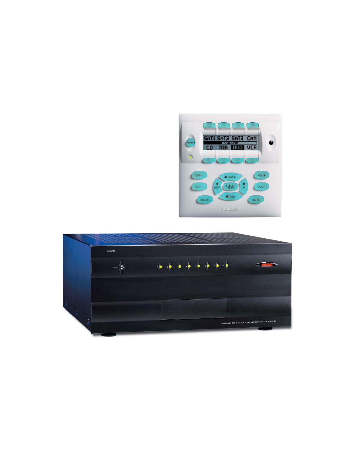
MODEL MRC88m
MODEL MRAUDIO8x8m
EIGHT ZONE – EIGHT SOURCE
AUDIO & AUDIO/VIDEO CONTROLLER/AMPLIFIER SYSTEMS
Page 2
Page: 2 Model MRC88m / MRAUDIO8x8m
SAFETY INSTRUCTIONS - READ BEFORE OPERATING EQUIPMENT
CAUTION: TO REDUCE THE RISK OF ELECTRIC SHOCK,
DO NOT REMOVE COVER (OR BACK)
NO USER-SERVICEABLE PARTS INSIDE
REFER SERVICING TO QUALIFIED SERVICE PERSONNEL
The lightning flash with arrowhead symbol, within an equil ateral tria ngle,
is intended to alert the user to the presence of un-insulated “dangerous
voltage” within the product’s enclosure that may be of sufficient magnitude
to constitute a risk of electric shock to persons.
The exclamation point within an equilateral triangle is intended to alert the
user to the presence of important operating and maintenance (servicing)
instructions in the literature accompanying the appliance.
WARNING
TO REDUCE THE RISK OF FIRE OR ELECTRIC SHOCK, DO
NOT EXPOSE THIS APPLIANCE TO RAIN OR MOISTURE.
This product was designed and manufactured to meet strict quality and safety standards. There a re, ho wever,
some installation and operation precautions, which you should be particularly aware of.
1. Read Instructions – All the safety and operating instructions should be read before the appliance is operated.
2. Retain Instructions – The safety and operating instructions should be retained for future reference.
3. Heed Warnings – All warnings on the appliance and in the operating instructions should be adhered to.
4. Follow Instructions – All operating and use instructions should be followed.
5. Water and Moisture – The appliance should not be used near water – for example, near a bathtub, washbowl, kitchen sink, laundry
tub, in a wet basement, or near a swimming pool, etc.
6. Carts and Stands – The appliance should be used only with a cart or stand that is recommended by the manufacturer. An appliance
and cart combination should be moved with care. Quick stops, excessive force, and uneven surfaces may cause the appliance and
cart combination to overturn.
7. Wall or Ceiling Mounting – The appliance should be mounted to a wall or ceiling only as recommended by the manufacturer.
8. Ventilation – The appliance should be situated so that its location or position does not interfere with its proper ventilation. For
example, the appliance should not be situated on a bed, sofa, rug, or similar surface that may block the ventilation openings; or,
placed in a built-in installation, such as a bookcase or cabinet that may impede the flow of air through the ventilation openings.
9. Heat – The appliance should be situated away from heat sources such as radiators, heat registers, stoves, or other appliances
(including amplifiers) that produce heat.
10. Power Sources – The appliance should be connected to a power supply only of the type described in the operating instructions or as
marked on the appliance.
11. Grounding or Polarization – Precautions should be taken so that the grounding or polarization means of an appliance is not
defeated.
12. Power-Cord Protection – Power- supply cords should be routed so that they are not likely to be walked on or pinched by items
placed upon or against them, paying particular attention to cords at plugs, convenience receptacles, and the point where they exit from
the appliance.
13. Cleaning – The appliance should be cleaned only as recommended by the manufacturer.
14. Power Lines – An outdoor antenna should be located away from the power lines.
15. Nonuse Periods – The power cord of the appliance should be unplugged from the outlet when left unused for a long period of time.
16. Object and Liquid Entry – Care should be taken so that objects do not fall and liquids are not spilled into the enclosure through
openings.
17. Damage Requiring Service – The appliance should be serviced by qualified service personnel when:
A. The Power-supply cord or the plug has been damaged; or
B. Objects have fallen, or liquid has spilled into the appliance; or
C. The appliance has been exposed to rain; or
D. The appliance does not appear to operate normally or exhibits a marked change in performance; or
E. The appliance has been dropped, or the enclosure damaged.
18. Servicing – The user should not attempt to service the appliance beyond that described in the operating instructions. All other
servicing should be referred to qualified service personnel.
© 2009 Xantech Corporation
Page 3

Model MRC88m / MRAUDIO8x8m Page: 3
TABLE OF CONTENTS
SAFETY INSTRUCTIONS - READ BEFORE OPERATING EQUIPMENT.............................................................2
TABLE OF CONTENTS...................................................................................................................................................3
SECTION 1: GENERAL INFORMATION & FEATURES............................................................. 8
GENERAL INFORMATION ...........................................................................................................................................8
SYSTEM OVERVIEW....................................................................................................................................................10
CONTROLLER/AMPLIFIER FEATURES .................................................................................................................11
KEYPAD FEATURES.....................................................................................................................................................12
MRC88M CONTROLLER/AMPLIFIER PANEL AND FEATURE DESCRIPTIONS............................................13
MRC88M FRONT PANEL FEATURES AND CONNECTIONS:........................................................................13
MRC88M REAR PANEL FEATURES AND CONNECTIONS:..........................................................................15
MRC88M KEYPAD FEATURE DESCRIPTIONS.......................................................................................................17
MRC88M KEYPAD - FRONT FEATURES:...................................................................................................17
MRC88M KEYPAD - REAR FEATURES AND CONNECTIONS:.....................................................................19
SECTION 2: INSTALLATION & CONNECTIONS ......................................................................20
INSTALLATION.............................................................................................................................................................20
OPERATION: OUT-OF-THE-BOX PRE TEST.........................................................................................20
MRC88M CONTROLLER/AMPLIFIER PHYSICAL LOCATION AND MOUNTING........................21
MRC88M KEYPAD PHYSICAL LOCATION AND MOUNTING........................................................22
MRC88M KEYPAD REMOVAL.............................................................................................................24
CONNECTING THE MRC88M CONTROLLER/AMPLIFIER.................................................................................25
SOURCE RELATED CONNECTIONS ............................................................................................................25
Source Component Connections................................................................................................................. 25
Zone Audio Inputs....................................................................................................................................... 26
IR Control Connections............................................................................................................................... 26
Sense Input Connections............................................................................................................................. 26
ZONE RELATED WIRING CONNECTIONS...................................................................................................27
Speaker Connections................................................................................................................................... 27
MRC88m Keypad CAT5 Cable Connections at the MRC88m Controller/Amplifier................................. 28
Video Connections (MRC88m Only).......................................................................................................... 28
Status Connections and Common Control Out............................................................................................28
Preamp Out.................................................................................................................................................. 29
CO1 and CO2 (Zones 7 & 8)....................................................................................................................... 29
Zone IR........................................................................................................................................................ 29
AC Power Connections............................................................................................................................... 29
CONNECTIONS AT THE ZONE LOCATION ..................................................................................................30
Keypad Connections and Jumper Settings.................................................................................................. 30
ZONE EXPANSION (CONNECTING TWO MRC88M CONTROLLERS) ..........................................................31
Linking Two MRC88m Controller/Amplifier Units...................................................................................31
Connecting Source Components................................................................................................................. 31
Speaker Connections................................................................................................................................... 33
Video connections....................................................................................................................................... 33
SETTING-UP THE MRC88M SYSTEM........................................................................................................................34
SECTION 3: PRE-PROGRAMMING THE MRC88M................................................................... 35
PLANNING THE SYSTEM............................................................................................................................................36
INSTALLING AND CONFIGURING THE DRAGMRC SOFTWARE ......................................................................36
COMPUTER REQUIREMENTS (MINIMUM) ..................................................................................................36
INCLUDED HARDWARE & SOFTWARE ITEMS ...........................................................................................37
CONNECTING THE MRC88M CONTROLLER/AMPLIFIER TO THE PC........................................................37
© 2009 Xantech Corporation
Page 4

Page: 4 Model MRC88m / MRAUDIO8x8m
DB9 Serial Connection ................................................................................................................................37
USB Serial Connection................................................................................................................................37
SOFTWARE INSTALLATION....................................................................................................................... 37
STARTING MRC88M DRAGON DROP-IR™ SOFTWARE...........................................................................37
SERIAL PORT SELECTION.........................................................................................................................37
VERIFYING COM PORT COMMUNICATION.............................................................................................38
(“WHO AM I” BASE UNIT VERSION VERIFICATION)................................................................................ 38
STARTING A PROJECT ...............................................................................................................................................38
LEARNING IR COMMANDS (CREATING PALETTE FILES)........................................................................................39
BUILT-IN IR CODE LIBRARY....................................................................................................................39
Testing IR Commands in the IR Library......................................................................................................39
LEARNING IR COMMANDS .......................................................................................................................40
Using the Palette Editor ...............................................................................................................................40
Recording Toggle Command Functions ......................................................................................................41
Editing Function Names in the Palette Editor..............................................................................................41
TO RENAME AN EXISTING FUNCTION ......................................................................................................42
Testing IR Commands in the Palette Editor.................................................................................................42
CREATING A PALETTE FILE......................................................................................................................42
EDITING BRAND, COMPONENT, AND FUNCTION LISTS ......................................................................... 43
Adding Brands.............................................................................................................................................43
Adding Components and Functions.............................................................................................................43
GETTING SOURCE COMMANDS FROM THE INTERNET ............................................................................. 43
Xantech.com ................................................................................................................................................43
Remote Central.com (Importing CCF Files and Discrete IR Comm ands)...................................................43
ENTERING RS232 COMMANDS (CREATING RS232 COMMAND PALETTE FILES)...................................................45
ENTERING RS232 COMMAND STRINGS....................................................................................................45
Using the RS232 Palette Editor....................................................................................................................45
Testing RS232 Command Strings................................................................................................................46
CREATING AN RS232 PALETTE FILE........................................................................................................47
SECTION 4: PROGRAMMING THE CONTROLLER................................................................. 48
CONFIGURING SOURCE ICONS ON MRC88M KEYPAD LCD.............................................................................48
ENTERING TEXT DIRECTLY ONTO THE ICONS..........................................................................................49
CREATING NEW ICONS.............................................................................................................................49
SELECTING ICONS FROM THE ICON GENERATOR.................................................................................. 49
DOWNLOADING SOURCE ICONS TO THE KEYPAD .....................................................................................49
PLACING COMMANDS ONTO THE VIRTUAL KEYPAD .....................................................................................50
SELECTING IR PALETTES FROM THE IR CODE LIBRARY..........................................................................50
SELECTING IR PALETTES ......................................................................................................................... 50
SELECTING RS232 COMMAND PALETTES................................................................................................ 50
SELECTING INTERNAL AMPLIFIER COMMANDS....................................................................................... 50
PLACING COMMANDS ON THE VIRTUAL KEYPAD................................................................................... 50
Programming Sequences (Macros)..............................................................................................................51
Timed Delays...............................................................................................................................................51
Repeat Commands.......................................................................................................................................52
Push & Hold (Tiered) Commands................................................................................................................52
EDITING BUTTONS (ON THE VIRTUAL KEYPAD)..................................................................................... 52
Delete Key ...................................................................................................................................................53
Delete Bank (Zone Level)............................................................................................................................53
Delete All (System Level)............................................................................................................................53
Punch (Zone Level)......................................................................................................................................53
Punch All (System Level)............................................................................................................................53
Copy.............................................................................................................................................................53
© 2009 Xantech Corporation
Page 5

Model MRC88m / MRAUDIO8x8m Page: 5
Paste ............................................................................................................................................................ 53
EDITING COMMANDS (IN THE MACRO COMMAND LIST WINDOW) .........................................................53
IR In Zone................................................................................................................................................... 54
Source Output.............................................................................................................................................. 54
Delete .......................................................................................................................................................... 55
Testing Commands Placed on the Virtual Keypad...................................................................................... 55
PROGRAMMING POWER MANAGEMENT AND SENSE TRIGGER CODES....................................................55
PROGRAMMING POWER MANAGEMENT ...................................................................................................55
PROGRAMMING SENSE TRIGGER CODES ..................................................................................................57
Programming of Sense input....................................................................................................................... 57
Polarity and Wiring of Sense Input............................................................................................................. 58
Current Sense De-Bounce Settings ............................................................................................................. 58
TESTING COMMANDS UNDER POWER MANAGEMENT AND SENSE TRIGGERS .........................................58
ZONE OPTIONS CONFIGURATION..........................................................................................................................59
DEFAULT SETTINGS SET IN BASIC MODE ARE AS FOLLOWS: ..................................................................59
NAME OF ZONE ........................................................................................................................................59
RC68 CODE GROUP...............................................................................................................................59
PRE AMP VOLUME ADJUST SETTINGS......................................................................................................60
IR LOOP BACK SETTINGS .........................................................................................................................60
TRANSFERRING THE PROJECT...............................................................................................................................61
SECTION 5: ADVANCED/EXPANDED PROGRAMMING ........................................................ 62
CONTROLLER OPTIONS PROGRAMMING...........................................................................................................62
ZONE AUDIO INPUT ..................................................................................................................................62
IR ROUTING..............................................................................................................................................63
BACK-LIGHT CONTROL.............................................................................................................................63
MODE OF OPERATION ..............................................................................................................................63
Whole House Mode..................................................................................................................................... 63
Priority Lockout Mode................................................................................................................................ 63
EXPANDED OPTIONS.................................................................................................................................63
Not Expanded.............................................................................................................................................. 63
Expanded..................................................................................................................................................... 63
RS232 SETTINGS.......................................................................................................................................64
Baud Rate, Data Bits, Stop Bits amd Parity Settings .................................................................................. 64
Process RS232 Input ................................................................................................................................... 64
MONITOR LOCKOUT MODE ......................................................................................................................64
Dynamic Monitor Lockout (Administrator)................................................................................................ 65
ZONE LINKING PROGRAMMING.............................................................................................................................66
STATIC ZONE LINK MODE ........................................................................................................................66
DYNAMIC ZONE LINK MODE....................................................................................................................67
LINK ALL DYNAMIC .................................................................................................................................68
LINK ALL STATIC .....................................................................................................................................68
CLEAR ALL ...............................................................................................................................................68
RS232 INPUT TRANSLATOR.......................................................................................................................................68
PROGRAMMING IR COMMANDS AND SEQUENCES....................................................................................69
Selecting IR Palettes from the IR Code Library.......................................................................................... 69
Selecting IR Palettes.................................................................................................................................... 69
Associating RS232 Commands with IR Control Codes.............................................................................. 69
Editing Individual Commands..................................................................................................................... 69
Testing Commands in the RS232 Input Translator..................................................................................... 69
RC68+ IR CODE TRIGGERED SEQUENCER ...........................................................................................................70
Programming RC68+ Triggered Sequences ................................................................................................ 70
Editing Individual Commands..................................................................................................................... 71
© 2009 Xantech Corporation
Page 6

Page: 6 Model MRC88m / MRAUDIO8x8m
PROGRAMMING INTERNAL AMPLIFIER COMMANDS.....................................................................................71
ZONE EXPANSION (CONNECTING MULTIPLE MRC88M CONTROLLERS).................................................73
PROGRAMMING IN EXPANDED MODE................................................................................................... 74
Enabling EXPANDED Mode...................................................................................................................... 74
Programming the System.............................................................................................................................74
PHYSICAL CONNECTIONS IN EXPANDED MODE ................................................................................... 74
RS232 CONTROL WHILE IN EXPANDED MODE ........................................................................................75
TRANSFERRING A PROJECT TO THE MRC88M ...................................................................................................77
UPLOADING MRC88M PROJECTS............................................................................................................................77
SAVING AND BACKING-UP FILES............................................................................................................................78
Automatic Save............................................................................................................................................78
Save Project As............................................................................................................................................78
Backing-Up Project Files.............................................................................................................................78
Using Backup Files......................................................................................................................................78
Backing-Up SmartPad and Palette Files ......................................................................................................78
FIRMWARE UPGRADE OPTIONS.............................................................................................................................79
DOWNLOADING FIRMWARE FILES FROM THE WEB ................................................................................. 79
WARM FIRMWARE UPGRADE...................................................................................................................79
COLD FIRMWARE UPGRADE.....................................................................................................................79
SECTION 7: TWEAKING THE SYSTEM................................................................................... 80
TEACHING A HAND-HELD REMOTE TO OPERATE THE MRC88M SYSTEM................................................80
TEACHING A HAND-HELD REMOTE USING AN RC68+ HAND-HELD PROGRAMMER .............................. 80
TEACHING A HAND-HELD REMOTE DIRECTLY FROM DRAGON DROP-IR™ ...........................................80
MAKING FINE ADJUSTMENTS.................................................................................................................................81
TRIMMING SOURCE AUDIO INPUT LEVELS .............................................................................................. 81
ZONE ADJUSTMENTS................................................................................................................................82
KEYPAD ADJUSTMENTS ........................................................................................................................... 82
IR Sensitivity Adjustment............................................................................................................................82
LCD Backlight Adjustment..........................................................................................................................82
SECTION 8: OPERATING INSTRUCTIONS............................................................................. 83
ZONE CONTROL...........................................................................................................................................................83
POWERING THE ZONE ON AND OFF......................................................................................................... 83
SOURCE SLECTION AND CONTROL........................................................................................................... 83
SETTING THE VOLUME............................................................................................................................. 83
MUTING AND UN-MUTING.......................................................................................................................83
ACCESSING TIER 2 COMMANDS...............................................................................................................83
ZONE SETTINGS ...........................................................................................................................................................84
SYSTEM STATUS.......................................................................................................................................84
AUDIO ADJUSTMENTS..............................................................................................................................84
DYNAMIC MONITOR LOCKOUT (PARENTAL CONTROL) ..........................................................................84
DYNAMIC ZONE LINK ..............................................................................................................................84
SECTION 9: APPENDIX................................................................................................................ 86
RS232 CONTROL...........................................................................................................................................................86
TYPES OF COMMANDS.......................................................................................................................86
INTERFACING TO THE RS232 COMPORT ........................................................................................ 86
ASCII STRING ‘INITIATING’ AND ‘TERMINATING’ CHARACTERS...........................................86
TROUBLESHOOTING..................................................................................................................................................94
RS232 AND EXPANSION PIN OUT INFORMATION...............................................................................................98
SPECIFICATIONS.........................................................................................................................................................99
CERTIFICATIONS ........................................................................................................................................................99
© 2009 Xantech Corporation
Page 7

Model MRC88m / MRAUDIO8x8m Page: 7
© 2009 Xantech Corporation
Page 8

Page: 8 Model MRC88m / MRAUDIO8x8m
Section 1: General Information & Features
GENERAL INFORMATION
The Xantech MRC88m System is the next generation in Whole-house Audio/Video Entertainment (WAVE™)
family of products - the first being the MRC44. This is a revolutionary whole-house audio/video entertainment
distribution, audio amplification and control system.
The MRC88m System consists of the MRC88m Controller/Amplifier, Eight LCD Keypads and Eight IR Emitters.
When combined with almost any Eight IR (or RS232) controlled audio/video source components (CD, DVD,
VCR, Satellite, etc.), using the MRC88m System is as easy as pushing a button.
The MRAUDIO8x8m is an Audio Only version of the MRC88m Controller. You get all the Power and Flexibility
of the MRC88m Controller including Built-in Amplification, Power Management, RS232 Control, Routable IR,
and expansion to 16 Zones and above in an Audio Only piece.
The MRAUDIO8x8m can be used as a stand-alone unit for audio only applications or in conjun ction with the
MRC88m to provide 16 Zones of A/V distribution and Control (8 Zones with Audio & Video and 8 Zones with
Audio only) to provide exactly what the job requires while meeting cost requirements.
The MRC88m system includes the following components:
• One MRC88m Controller/Amplifier (Part No. MRC88mCTL)
• Eight MRC88m Keypads(Part No. MRC88KPW)
• Eight IR Emitters (Part No. 283M)
• One DB9 programming cable to connect to the RS232 serial port on your PC (Part No. 05913410)
• One male DB15 to male DB15 cable with null modem for linking two MRC88m Controllers (Part No.
05913555)
• CD-ROM Disc contains the MRC88m Dragon Drop-IR software (Part No. 03900785-01)
• MRC88m System Installation Instructions (Part No. 08901180)
• Six speaker WECO connector plugs (Part No. 05997400
• 24 Keypad jumpers (for Zone Termination, Keypad Address and IR Sensor Enable)
• MRC88m Keypad Installation Kit which includes Eight sets of installation brackets (Part No. 03079565-01),
an installation template (Part No. 09590255), a Keypad removal tool (Part No. 03025280) and the Keypad
Installation Instructions (Part No. 08901175)
• Caution card
Optional Accessories:
• Secondary Keypads: White: Part No. MRC88KPW; Black: Part No. MRC88KPB; Almond: Part No.
MRC88KPA; Ivory: Part No. MRC88KPI (Also available in Dual Gang J-Box Mount – Model MRC
• SmartPad LCD™ Keypads: Models SPLCD39G, SPLCD64G, SPLCD64Video; TS57LCD
• MRCREM (Zone Companion Remote – no programming required)
• MRC44CB1 Connecting Block
• CSM1 Current Sensing Module
• URC-2P or URC-2B Universal Hand-Held Remote Controller
• RS2321X8 Router: Serial Router expanding a single MRC or MRAUDIO RS232 output to 8 Serial Ports
• ZAIP Zone Audio Input Kit: For use with Zone Audio Inputs. Send and Receive Stereo Audio over CAT5
• Expansion Port RS232 Adaptor Cable: Turns Expansion Port into another useable RS232 Port (Part No.
05913665)
• External IR Receivers: 480-00 Dinky Link™ Series (Comes in Standard and CFL Friendly Versions)
490 Micro Link™ Series (Comes in Standard and Plasma Friendly versions); 780 Series J-Box & 291
Series Hidden Link™ IR Receivers (Comes in Standard, CFL and Plasma versions)
© 2009 Xantech Corporation
Page 9

Model MRC88m / MRAUDIO8x8m Page: 9
IMPORTANT NOTE: A MRC88m System can be a single controller with keypads for up to Eight zones or two
connected controllers and keypads for up to Sixteen zones. There are three different setup modes in the
Dragon Drop-IR Software. The Basic mode allows quick setup and programming for an Eight zone system. It
assumes all zones will use factory defaults and will behave exactly the same. The Advanced mode allows
customization of system configuration for functions such as zone link, monitor lockout, unique IR programming
by zone, etc. The Expanded mode allows programming of systems with more than Eight zones using linked
MRC88m Controllers.
Each section of this manual will indicate which sections apply to the three programming modes and setups. A
section with: BASIC/ADVANCED/EXPANDED would apply to all system configurations. A section with:
ADVANCED/EXPANDED would only apply to systems requiring advanced programming or that have more
than Eight zones, etc.
In the Expanded mode, the controller for zones 1-8 will be referred to as the PRIMARY CONTROLLER. The
controller for zones 9-16 will be referred to as the SECONDARY CONTROLLER.
NOTE: All programming and features of the MRC88m directly apply to the MRAUDIO8x8m with the exception
of Video Distribution and Video Sensing.
© 2009 Xantech Corporation
Page 10
Page: 10 Model MRC88m / MRAUDIO8x8m
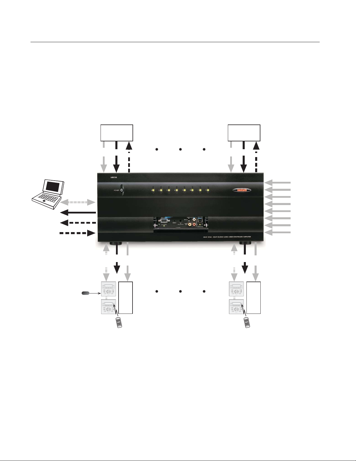
SYSTEM OVERVIEW
The MRC88m is a Eight-source Eight-zone audio/video distribution and control system. The System is
comprised of a Control Amp, Eight LCD Keypads, and Eight 283M IR Emitters. Together the Control Amp and
the Keypads make up a Whole-house Audio/Video Entertainment system. The Control Amp acts as the Server
and the Keypads act as the Clients. The end users interact with the Keypads in order to control all aspects of
Audio/Video Distribution and Control. This System allows the end user to accomplish the following: 1) Distribute
amplified Stereo Audio and Composite Video from Eight independent Sources to Eight separate Zones. 2)
Control the Volume, Mute, Bass, Treble, and Balance for each of the eight Zones. 3) Control most standard
source components via IR and/or RS232 commands. Two Control Amps can be linked to create systems with
up to Sixteen zones.
Audio/Video
Source 1
Audio/Video
Source 8
DB9 / RS232
Common Status
Common IR
IR Learning Eye
Optional
External IR
Receiver
Primary
Keypad
Optional
Secondary
Keypad
Audio
Power
&
Sense
Video
Serial
RJ45RS422
& IR
Zone
Status
Audio
Video
IR
&
Zone 1 Zone 8
POWER
CH
PAUSE
SELECT
CH
PLAY
FF
REW
STOP
STATUS
POWER
CH
PAUSE
SELECT
CH
PLAY
FF
REW
STOP
STATUS
To Built-In
Keypad
IR Receiver
Zone 1
VOL
VOL
Video
MUTE
Monitor
&
Speakers
VOL
VOL
MUTE
Primary
Keypad
Optional
Secondary
Keypad
Figure 1 - System Block Diagram
Audio
&
Video
Serial
RJ45-
RS422
& IR
POWER
CH
CH
STATUS
POWER
CH
CH
STATUS
To Built-In
IR Receiver
PAUSE
SELECT
PLAY
REW
STOP
PAUSE
SELECT
PLAY
REW
STOP
Keypad
FF
FF
Power
Sense
VOL
VOL
MUTE
VOL
VOL
MUTE
Zone
Status
Audio
Video
Zone 4
Video
Monitor
&
Speakers
IR
Input 1
Input 2
Input 3
Music
Input 4
Server
Zone
Input 5
Inputs
Input 6
Input 7
Input 8
&
© 2009 Xantech Corporation
Page 11

Model MRC88m / MRAUDIO8x8m Page: 11
CONTROLLER/AMPLIFIER FEATURES
• Zones: Eight, expandable to 16-zones with the addition of a second Controller/Amplifier and additional
keypads
• Sources: Eight audio AND VIDEO sources (Video applies to MRC88m only). Any zone can select any
source. Same source can be selected in multiple zones. Several modes of control:
Whole-hous e mode – selection and control of any source from any zone.
Priority mode – any zone can select and monitor a source, but only the first zone to select that source
can control it
Link mode – multiple zones can be linked together to act as a single zone for source selection and
control. Each zone maintains independent volume and mute controls.
Monitor lockout – prevents certain zones from selecting certain sources.
• Local Zone Audio Inputs: Eight zone-specific audio inputs. When activated, overrides source-one audi o
inputs allowing each zone to have its own dedicated Audio Source by selecting
source-one.
• IR Learning: IR commands can be learned from external hand-held remotes through the
Controller/Amplifier’s built-in IR learning eye or they can be generated from the MRC88m’s built-in IR code
library.
Internal IR Code Library: Built in IR Code Library. Contains all Major Brand Component IR commands. No
need to ‘learn’ commands.
• Macros: can be built using IR, audio control, RS232, repeat or delay commands and associa t ed with a
specific button or event. They can be triggered by a keypad button press, an RC68+ IR code, an
MRC88m compatible keypad command, control sense status, video sense status or by RS232. Up
to 40 IR commands can be issued in a single Macro.
• Audio/Video loop-through on all Eight source inputs (Video applies to MRC88m only)
• Power Management: Keeps all components Power States in-sync with Zone Power Status
All Eight video source inputs have built-in NTSC/PAL sync sensing (Applies to
MRC88m Only)
All Eight sources have current sense inputs for use with a CSM1 Current Sensor
• Preamp Outs for all Eight zones
Frequency response: 12 Hz to 55KHz (±3dB)
THD: <0.08%.
Signal-to-noise ratio: > 96dB A-weighted
• Amplification: Zones 1 through 6 have built-in stereo audio amplifiers at 35 Watts per channe l
Zones 7 and 8 are designed to be used with external amplifiers, ideally with either the
PA435X (for two zones of stereo audio at 35 Watts per channel) or the PA4100X (for
two zones of stereo audio at 100 Watts per channel) with built-in POWER and MUTE
control via Control Ports CO1 and CO2
• Eight zone-specific video outputs (Applies to MRC88m only)
• IR Emitter Outputs: Eight source-specific IR emitter outputs
One common IR emitter output
Eight zone-specific IR emitter outputs
Eight in-the-zone IR emitter outputs via the MRC88m Keypad rear panel emitter output
- permitting IR commands originating in the zone to be looped back to the zone
allowing the MRC88m to control components physically located in the zone
• Status Outputs: Eight zone-specific 12V status outputs
One common 12V status output (Labeled Control Out)
• RS232 Com/USB Com (Front Panel): Communications port used to program the system using Dragon
Drop-IR™ Software
RS232 COM PORT (Rear): Allows the Controller/Amplifier to be controlled by a PC or other RS232 device
OR to control other devices that communicate via RS232 such as certain home
theater components, lighting or HVAC devices
EXPANSION PORT: Allows connection to another MRC88m or MRAUDIO8x8m for 16 Zones of seamless
control. Can also be used as an additional RS232 Control port (requires
Xantech Part Number 05913665)
• Eight MRC88m Keypad connections - RJ45 connectors / CAT5 cable
© 2009 Xantech Corporation
Page 12

Page: 12 Model MRC88m / MRAUDIO8x8m
KEYPAD FEATURES
• Flush-mount, snap-in wall unit with universal wall mounting plate. Requires a 4" x 4" hole cutout in wall
(use included template).
• Connects to MRC88m Controller/Amplifier via CAT5 cable terminated with RJ45 connectors.
• Configurable LCD panel (via supplied Dragon Drop-IR™ software).
• 20 buttons (8 source select, 11 function, 1 power).
• Programmable dual functionality (tiered) “push-and-hold” on most buttons.
• Backlit LCD and buttons w/ rear panel brightness adjustment
• Variable backlight timeout.
• Bi-colored Status LED for power and status.
• Broadband IR receiver (30KHz to 100KHz) w/rear panel sensitivity adjustment.
• Rear Panel IR Input connections for addition of external IR Receivers and/or Keypads
• Rear Panel IR IN Zone Output connections for control of in-room components
• Two RJ45 connectors allow multiple keypads to be daisy-chained (up to 4 keypads per zone)
• Optional New Construction back-box (Xantech Part# MRCBOX) for Keypad mounting.
© 2009 Xantech Corporation
Page 13
Model MRC88m / MRAUDIO8x8m Page: 13
MRC88m CONTROLLER/AMPLIFIER PANEL AND FEATURE DESCRIPTIONS
4
1
3
PROTECT
OFF
ON
6
2
PROTECT
OFF
ON
5
8 10
7
9
14
13
15
11
12
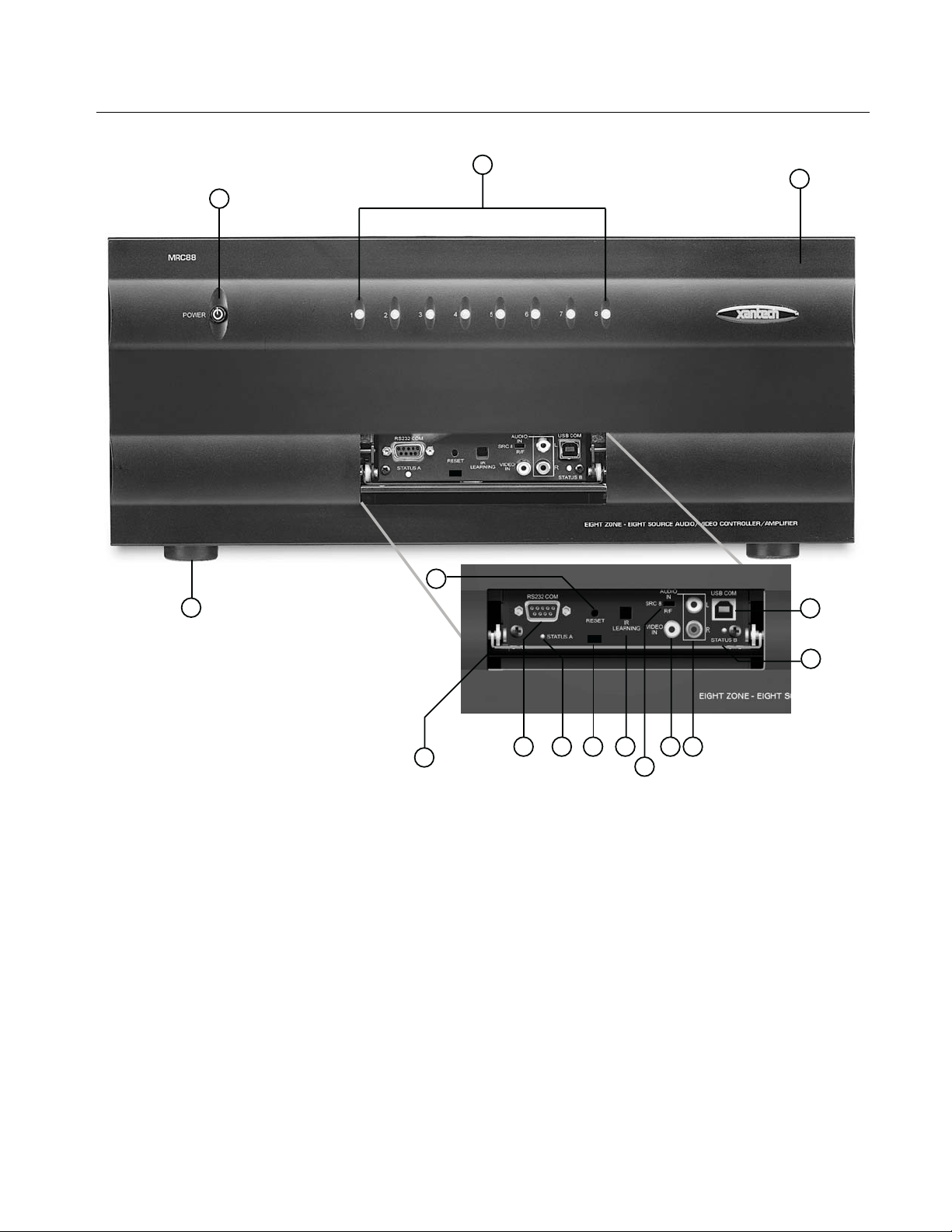
Figure 2 – The Model MRC88m Controller/Amplifier – Front Panel Features and Functions
MRC88M FRONT PANEL FEATURES AND CONNECTIONS:
1. Front Panel.
2. Chassis Feet. Set high enough to provide through-chassis cooling by natural convection.
3. Master AC Line On/Off Switch. Turns AC power On/Off to the entire unit.
4. Power and Status LED Indicators. Eight indicators, one for each Zone, provide the following status
information:
System Status (Power-Up Mode)
a) Slow Orange Blink – indi cates general initialization is occurring.
b) Fast Green Blink – indicates that a keypad on the associated zone is currently being initialized.
c) Fast Red Blink – indicates that the master keypad on the associated zone is not responding to
initialization.
d) Fast Orange Blink – indi cates that the slave keypad on the associated zone is not responding to
initialization.
e) All Lights Off – initialization is done, system is ready for operation.
© 2009 Xantech Corporation
Page 14

Page: 14 Model MRC88m / MRAUDIO8x8m
Zone Status (Active-Operational Mode)
a) Steady Green – indicates that the Zone is Active (Keypad ON), is not muted and is not within 5 dB of
MAX-V.
b) Steady Red – indicates that the Zone is Active, is not muted and is within 5 dB of MAX-V.
c) Slow Green Blink – indicates that the Zone is in the Active, is muted and is not within 5 dB of MAX-V.
d) Slow Red Blink – indicates that the Zone is Active, is muted and is within 5 dB of MAX-V.
e) Fast Green Blink – indi cates that Zone is Active, is being Ramped Up or Down and is not within 5 dB of
MAX-V.
f) Fast Red Blink – indicates that the Zone is Active, is being Ramped Up or Down and is within 5 dB of
MAX-V.
f) Off to indicate that Zone is in Not Active (Keypad OFF).
5. Front Panel Access Door. Push gently on lower half of door to open. Allows access to programming
connections, Level Reset and Front Panel Source 8 A/V Input.
6. Level Reset. Pressing this button twice within 1 second restores all of the Factory Default Settings for all
zones. The Factory Defaults are as follows:
• Mute Off
• Treble and Bass Flat
• Balance Centered
• Z-Adjust Treble and Bass Flat
• Z-Adjust Balance Centered
• Z-Adjust Max-V Cleared
• Z-Adjust Max-On-V Cleared
• Trim Levels Cleared
• IR Code Group set to A8
NOTE: The Control Amp will always return to last set values (plus any unaltered factory defaults) after main
power shut down or after any power interruptions.
7. IR Learning Eye. The IR Eye on the MRC88m Controller front panel allows teaching IR Codes to Dragon
Drop-IR™ via the Control Amp when connected to a PC ‘s com port.
8. RS232 Com Port. DB9 Connector. Used to program the MRC88m Controller from a PC using Dragon
Drop-IR™ Software and for Firmware Upgrades.
9. PROTECT On/Off Switch. Selects between Programming Mode (OFF position) and PROTECT (ON)
position to keep program secure in memory.
10. STATUS A Led. Green Activity LED, lights during Program Download from Dragon Drop-IR™ Software,
during IR Learning and for Firmware Upgrades when using the RS232 Port located on the front panel
11. USB Com Port. Used to program the MRC88m Controller from a PC using Dragon Drop-IR™ Software and
for Firmware Upgrades.
12. STATUS B Led. Green Activity LED, lights during Program Download from Dragon Drop-IR™ Software,
during IR Learning and for Firmware Upgrades when using the USB Port located on the front panel.
13. Source 8 AUDIO IN L/R. Front panel Source 8 line level audio input. Gold-plated RCA Jacks for use with
any desired A/V source component such as Camcorder, Video Game or other.
14. Source 8 VIDEO IN. Front panel Source 8 composite video input. Gold-plated RCA Jacks for use with any
desired A/V source component such as Camcorder, Video Game or other. (Applies to MRC88m Only)
15. Source 8 Front/Rear Selector Switch. Selects whether the Source 8 Audio/Video inputs will come from
the Front (F) or Rear (R) panel jacks.
© 2009 Xantech Corporation
Page 15
Model MRC88m / MRAUDIO8x8m Page: 15
27
22
23
20
2426
30
29
25
19
28
17
18 16
34
21
33
31
32
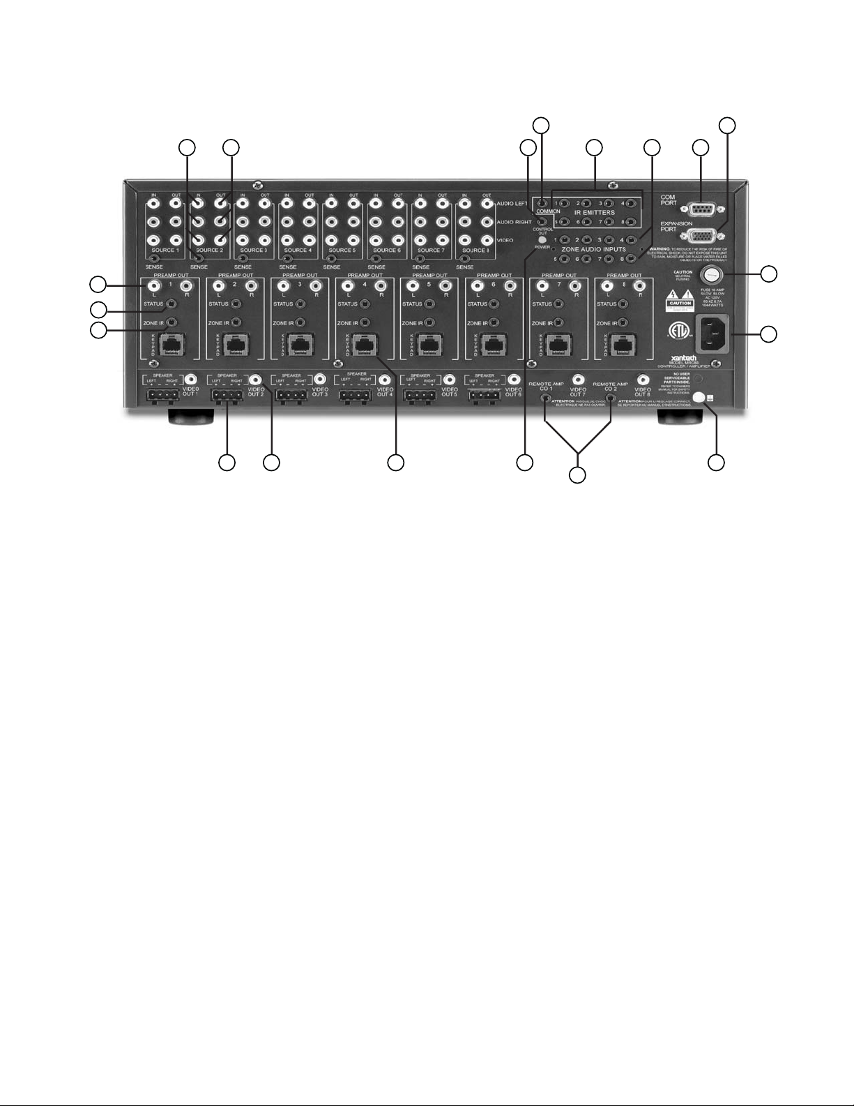
Figure 3 – The Model MRC88m Controller/Amplifier – Rear Panel Connections and Functions
MRC88M REAR PANEL FEATURES AND CONNECTIONS:
16. Keypad Terminals (8). Each Zone has one RJ-45 jack for Keypad Interface. Each connecto r interfaces the
following: Power (Enough for 1 Primary & up to 4 Secondary Keypads per Zone), RS-485 Data I/O, and IR
Input.
17. Speaker Terminals (6). Plug-in 4-terminal screw type connectors for zones 1 thru 6, permit speaker wire
sizes up to 12AWG.
18. Composite Video Output (8). RCA type connector sends zone selected, source video to the composite
video input on a zone TV or modulator (Applies to MRC88m only).
19. Status Out (8). Provides a control output of +12 VDC that turns on and off with the zone to d rive voltage
sensing relay modules and AC strips.
20. Control Out (8). Mono 3.5mm Mini Phone Jack provides a Control Output that goes high (+12 volts) when
any Zone is first turned ON and goes low (0 volts) when the last Zone is turned OFF. [Tip=+VDC;
Shield=GND]
21. Remote Amp Control Out (CO1 & CO2). Stereo 3.5mm Mini Phone Jack connects to CONTROL IN
jack of Remote Amp PA435X or PA4100X. Provides STANDBY and MUTE Control of remote Amp from
Zone 7 (CO1) and Zone 8 (CO2). [Tip = STANDBY Logic; Ring = MUTE Logic; Shield = GND]
22. Source Component Input Connections (8)
a) Source Audio Inputs. Gold-plated RCA Jacks for Stereo/Dolby Pro line level audio input from source
components.
b) Source Video Inputs. Gol d-plated RCA Jacks for composite video input from source components
(Applies to MRC88m only).
© 2009 Xantech Corporation
Page 16

Page: 16 Model MRC88m / MRAUDIO8x8m
c) Sense Inputs. 3.5mm Stereo Mini Phone Jacks for use with the CSM1 MRC88m Current Sense
Module.
23. Source Loop-Thru Connections (8).
a) Audio Loop-Thru. Parallel Connection to Audio Inputs for connecting Audio Source to another MRC-
88 in Expanded Mode or to other local devices. This is not an active output.
b) Video Loop-Thru. Buffered Video Connection for connecting Input Video Source to another MRC-88 in
Expanded Mode or to other local devices. NOTE: Since this is a Buffered video connection, this loopthru is not active when POWER is removed from the MRC88m (Applies to MRC88m only).
24. Zone Audio Inputs (8). 3.5mm Stereo Mini Phone Jack for Zone specific stereo audio Server Inputs. Zone
Audio Inputs override rear panel, Source 1 connection. Allows each of the 8 Zones to have a dedicated
Server Output by selecting Source 1 on keypad.
25. Zone Audio Pre-Amp Out (8). Gold-plated RCA Jacks for connecting Zone Audio Output to an external
amplifier. For use with applications where either more power is required for Zone or passing to a Dolby Pro
compatible receiver for theater quality audio in zone.
26. IR Emitters (1-8). 3.5mm Mono Mini Phone Jacks. These mini jacks are for the connection of IR emitters to
control individually the eight source components. These jacks are “steerable” with Dragon Drop-IR™
Software for IR Routing and Priority Lockout. IR received from a Zone will be routed to the emitter port
corresponding to the Zones active source selection. Can also be configured as 8 common emitter ports
(ADVANCED only) (See: Section 5: Controller Options Programming).
27. IR Emitter (Common). 3.5mm Mono Mini Phone Jacks. Single Common IR Output that can be used to
control devices such as Multi Zone Audio Server, motorized drapery systems, TV lifts and lighting systems
or any other IR controlled component. IR Received from any Zones Keypad will be output the Common
emitter port regardless of source selection.
28. Zone IR Out (8). 3.5mm Mono Mini Phone Jacks. IR received from a Zone will always be passed to the
corresponding Zone IR output. This can be used to control Zone Specific components not located in the
zone.
29. Com Port. DB9 RS232 Co ntrol Port allows full control from an external PC component of all Internal
Amplifier Commands of the MRC88m Controller and the ability to trigger programmed IR Macros for cont rol
of devices connected to the Controllers emitter ports. The Com Port can also be used in the reverse to send
ASCII/Hex commands OUT to control an external RS232 device directly from the MRC88m Keypad and/or
handheld remote.
30. Expansion Port. DB15. Allows two MRC88m’s to be connected together, via included Expansion Cable, to
provide an 8 Source/16 Zone system with full control between units. Can also be utilized as a secondary bidirectional RS232 Port.
31. User Replaceable Fuse. 10 AMP 250 VAC, Slow Blow Fuse (Domestic version). 5 AMP 250 VAC, TimeLag Fuse (European version).
32. AC Power Input. Standard IEC 3-Conductor AC Line Cord Receptacle for plug-in of a 3-conductor power
line cord.
33. Grounding Screw. “Knurled Screw” provides a means for chassis connection to earth ground or to other
Audio/Video products to aid in the reduction of system noise.
34. Power On/Off LED. This LED indicates the Main Power ON/OFF Condition of the MRC88m Controller.
© 2009 Xantech Corporation
Page 17
Model MRC88m / MRAUDIO8x8m Page: 17
MRC88m KEYPAD FEATURE DESCRIPTIONS
7
2
4
6
5
3
11
12
101413
1
9
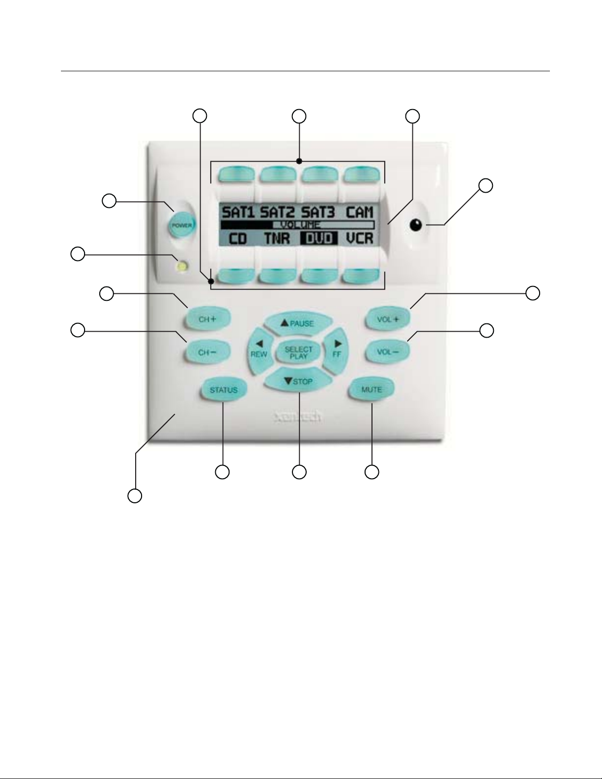
Figure 4 – The Model MRC88m Keypad – Front Panel Features and Functions
MRC88M KEYPAD - FRONT FEATURES:
1. MRC88m Keypad.
2. Power. Turns the zone ON and OFF. Can be programmed with IR codes or sequences.
3. IR Sensor. Receives IR from hand-held remotes to control both source components and the MRC88m
system. A Programmable Learning Remote such as the Xantech URC2 is recommended for integrating the
IR commands of the MRC88m and source components into a single controller. Compatible with most
brands of remote controls, though some may not be programmable and will therefore only control the
source components.
4. Status Indicator LED. Will indicate zone/system status and will flash as IR is received at the IR Sensor.
These indicators, one for each Keypad, provide the following Information:
a) LED Off = Zone OFF
b) Steady Green = Zone ON
c) Slow Green Blink = Zone MUTE
8
© 2009 Xantech Corporation
Page 18

Page: 18 Model MRC88m / MRAUDIO8x8m
d) Fast Red Blink = IR Sensor INPUT or Keypad OUTPUT
e) Fast Amber Blink = System BUSY
5. LCD Display. When the zone power is ON, the LCD will indicate the selected source, zo ne volume level,
zone and system status and other system conditions. The display is automatically backlit when any button
is pressed (backlight is programmable via Dragon Drop-IR™ software).
6. Source 1-4 Selector Buttons. Pressing of Source Button selects the corresponding source’s Audio/Video
signal to be played in the Zone of the keypad pressed. Pressing of the Source Button will reverse the
source icon on the LCD Display and sends IR commands programmed to the button (if any) to the
corresponding source and common emitter outputs as well as Zone Emitter port.
7. Source 5-8 Selector Buttons. Pressing of Source Button selects the corresponding source’s Audio/Video
signal to be played in the Zone of the keypad pressed. Pressing of the Source Button will reverse the
source icon on the LCD Display and sends IR commands programmed to the button (if any) to the
corresponding source and common emitter outputs as well as Zone Emitter port
8. Vol
9. Vol
10. Mute. Mutes zone speaker output. Sends IR commands programmed to this button (if any) to the selected
11. CH
12. CH
13. Status. Displays zone and system status. Allows access to Dynamic Zone Linking and Zone EQ/Balance
14. Select/Play, Stop, Pause, Rew, FF. Each send IR commands programmed to these buttons to the
+. Increases zone volume and moves the Volume Bar on the LCD Display to indicate volume level
(non-programmable).
-. Decreases zone volume and moves the Volume Bar on the LCD Display to indicate volume level
(non-programmable).
source emitter, common emitter, and zone emitter outputs.
+. Sends IR commands programmed to this button to the selected source emitter, common emitter,
and zone emitter outputs.
-. Sends IR commands programmed to this button to the selected source emitter, common emitter, and
zone emitter outputs.
settings (non-programmable).
selected source emitter, common emitter, and zone emitter outputs.
© 2009 Xantech Corporation
Page 19
Model MRC88m / MRAUDIO8x8m Page: 19
JP1
19
17
JP2
22
15
24
18
20
21
23
16
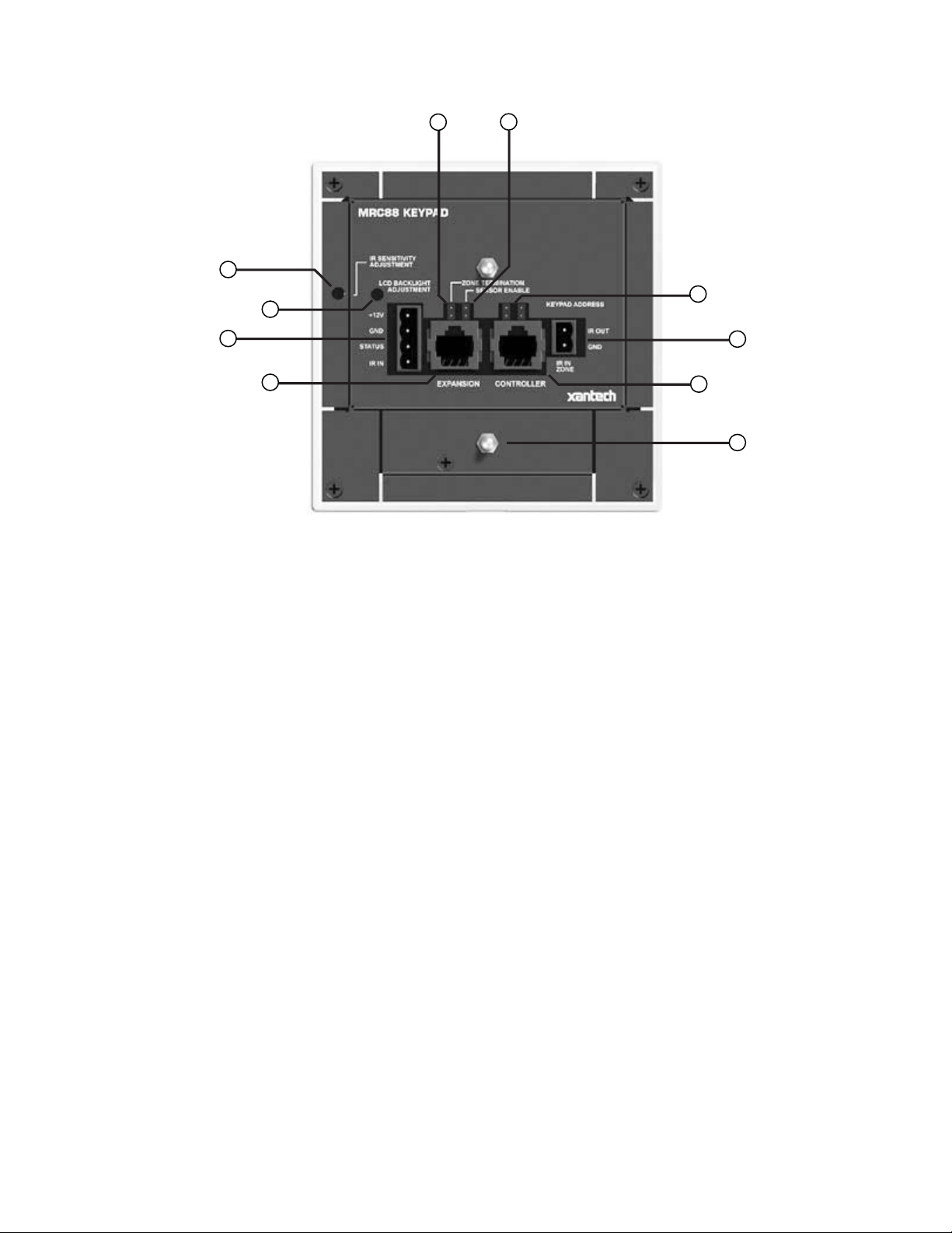
Figure 5 – The Model MRC88m Keypad – Rear Panel Features and Functions
MRC88M KEYPAD - REAR FEATURES AND CONNECTIONS:
15. Controller Terminal. RJ45 Jack. Connects Keypad to zone keypad input on MRC88m Controller via CAT5
cable.
16. Expansion Terminal. RJ45 Jack. Allows keypad to be daisy chained to another keypad for multiple control
locations within a zone. Up to 4 keypads are supported per zone.
17. Keypad Address. Pair of Jumpers. Used to assign Keypad Address. Each Keypad in the zone must have a
unique address (up to 4 keypads in a Zone).
18. Zone Termination. Jumper. Do not remove jumper if there is only one keypad in a zone. If there is more
then one keypad in a zone, remove from all but the last keypad in the daisy chain configuration.
19. Sensor Enable. Jumper. Enables IR sensor on Keypad. Remove when using an external IR receiver.
20. IR Sensitivity Adjustment. Carefully adjust for background light level to prevent false triggering of the IR
circuits. Slowly turn counter-clockwise to reduce sensitivity.
21. LCD Backlight Adjustment. Adjusts brightness of LCD backlight. This adjustment does not affect the
backlight level for the buttons. Slowly turn counter-clockwise to reduce brightn ess.
22. IR In-Zone. 2-Terminal WECO style socket - Zone IR out for local ‘In-Zone’ emitter out. Used for IR control
of equipment in the same location as the keypad. Any IR generated from within the Zone (or routed to that
zone from another) will be output from the IR IN-Zone connector as well as the Zone IR jack on the rear of
the Controller. This feature is ‘selectable’ via Dragon Drop-IR™ Software.
23. External IR Terminal Block. 4-Terminal WECO style socket – Allows connection of other Xantech IR
Receivers and/or Keypads to be used in conjunction with the MRC88m. (i.e. Use Waterpad Keypad in subzone in shower or outdoor zone or Plasma Friendly IR Receiver in place of Keypad IR Receiver).
24. Snap-in Pins. These pins snap into the MRC88m Keypad wall bracket for mounting.
© 2009 Xantech Corporation
Page 20

Page: 20 Model MRC88m / MRAUDIO8x8m
Section 2: Installation & Connections
INSTALLATION
OPERATION: OUT-OF-THE-BOX PRE TEST
(BASIC/ADVANCED/EXPANDED)
The MRC88m is shipped to operate basic functions ‘Out-Of-The-Box’ without any programming. Simply by
plugging in keypads via standard CAT-5 RJ45 terminated patch cable and powering the controller ‘on’, you can
control Source Selection, Volume Up/Down and speaker Mute capabilities.
Completing the Out-Of-The-Box Pre-Test will verify that all sources and zone components are working properly
to select and distribute audio and video prior to programming with Dragon Drop-IR™. This will ensure that the
unit is indeed functioning correctly ‘prior’ to fixed installation and allow proper troubleshooting procedures if a
problem is encountered. Instructions regarding full programming for specific components an d features will
follow.
Note: For ‘EXPANDED’ configuration, test both units individually as outlined below.
Note: For simplicity of test set-up, only one Source Component, one pair of speakers, and one TV/Video
Monitor will be necessary.
For the pre-test, you will need the following:
8-RJ45 Terminated CAT5 cables. (Pre test cables prior to use – See Caution below)
1-Audio/Video Source Component (i.e. VCR, DVD or other) [Will be used to test ALL Source Inputs]
1 Audio/Video RCA Harness (Capable of Audio Left/Right and Video)
1-Pair of speakers with Speaker Cable properly terminated into a 4 conductor WECO Plug [Will be used to
test Speaker outputs]
1-TV or Video Monitor [Will be used to test ALL Video Outputs – MRC88m only]
8-283M Blink Emitter
All 8 MRC88m Keypads
MRC-88 Controller/Amplifier
PA435X Two-Zone Stereo Amplifier (or other)
2 Pair of Stereo RCA Phono cables (for PA435X)
AC Cord
1. Connect MRC88m Controller/Amplifier as shown in Figure 13 to:
a) All MRC88m Keypads via CAT5 Cables
b) Pre Amp Out of Zones 7 and 8 to PA435X Zones 1 and 2 Audio Input
c) Audio/Video Source to SOURCE 1 Audio Left/Right and Video Input terminals
d) TV or Monitor to Video Out 1 (MRC88m Only).
e) Speakers to Speaker Output #1
f) All 8 IR emitters to IR Emitter Ports 1 thru 8 (rear connection Item #26)
g) AC Power for MRC88m Controller and Audio/Video Source Component
2. Press “Power On” button on the front of the MRC88m Controller/Amplifier (wait for front panel LED’s to stop
flashing – should be less than 20 seconds).
3. Power ON the Zone 1 TV/monitor and select the appropriate input (on the TV or monitor).
4. Power ON the Source Component and press play.
5. Place the emitter from IR Emitter Port 1 near the front of the Source Components IR Sensor window.
6. Press “POWER” on the Zone 1 Keypad.
7. Select “SRC1” on the Zone 1 MRC88m Keypad.
a) If Source 1 is an Audio/Video component, the video content of the source connected to the Source 1
inputs should be seen on the zone 1 TV/monitor.
© 2009 Xantech Corporation
Page 21
Model MRC88m / MRAUDIO8x8m Page: 21
b) Press “VOL+” on the Zone 1 Keypad. The Volume bar should move on the Keypad and the audio
content of the source connected to the Source 1 inputs should be should be heard through the Zone 1
speakers.
c) Press “MUTE” on the Zone 1 Keypad. The Zone 1 speakers will mute. Press MUTE again and the
speakers will un-mute. (Pressing VOL+ or VOL- will also un-mute the speakers).
d) Use the source 1 original equipment remote and verify that all source functions operate when aiming
the remote at the Zone 1 Keypad IR sensor.
e) Press “POWER” on the Zone 1 Keypad and verify ALL Status LED’s on the Controller Front Panel are
OFF.
8. Move the Audio/Video Source component to SOURCE 2 Audio Left/Right and Video Input terminals;
Speakers to Speaker Output #2 and the TV/Video Monitor to Video Out #2.
9. Repeat Steps 5 thru 8 for source/Zone 2 thru 8
Note: For Zones 7 & 8 Speakers will be connected to the Speaker A and B output of the PA435x
Caution: Power voltage for the keypad is transmitted along the CAT5 cable! Incorrect wiring on this cable
can destroy the MRC Keypad. Please test the cable connections using a proper CAT5 cable tester
or using a Multimeter to check Pin to Pin continuity and for possible shorts. Using either method, it is
advisable to measure pins 3 and 6 to verify proper voltage with a Multimeter. A 12Vdc measurement
should be read when the positive probe is on pin 6 and the negative probe is on pin 3. See Figure
10.
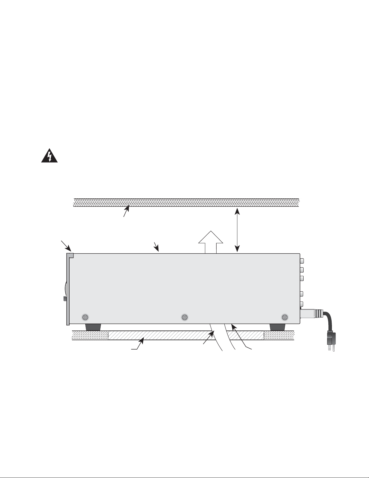
Upper shelf, component, wall, etc.
2-inch spacing
MRC88
Keep perforations on top cover free
of obstructions!
To maximize air flow, route
single large opening in lower shelf.
Convection
Airflow
(minimum)
Keep perforations on bottom
plate free of obstructions.
Figure 6A: MRC88m CTLR mounting
MRC88M CONTROLLER/AMPLIFIER PHYSICAL LOCATION AND MOUNTING
(BASIC/ADVANCED)
When you mount the MRC88m Controller, you should plan its location carefully. Pay close attention to each of
the following factors (refer to Figure 6A above):
1. The amplifier is convection cooled. That is, it depends on the natural free flow of air up through the slot
perforations in the bottom plate, over the internal heat dissipating fins, then out the top cover, for adequate
cooling.
© 2009 Xantech Corporation
Page 22
Page: 22 Model MRC88m / MRAUDIO8x8m
2. If mounted in an equipment cabinet or other confining location, allow at least 2 inches of space above the
top cover. Be sure there are large openings in the shelf below the unit and in the cabinet to allow the entry
of cool air and the escape of warm air.
3. If the cabinet contains other heat generating components or you are using several MRC88m's in a large
multi-zone system, you will have to pay even closer attention to adequate ventilation.
4. Do not hesitate to use fans (quiet, boxer type), if necessary, to ensure a constant flow of air through the
MRC88m's and the other heat generating components.
5. When mounting in a 19" (483mm) rack, adding a single RU (Rack Unit) spacer above and below the
MRC88m will improve convection in heavy use applications. Note: Rear support may be required.
[One Rack Unit size = 1-3/4" (44.5mm) in height].
6. In multi-zone installations, you will have large bundles of wire and cable to accommodate audio, video and
speaker connections. Be sure to allow enough room for the leads and dress them in such a manner so as
not to block airflow.
7. The MRC88m is designed for mounting on flat horizontal surfaces. When mounting into a 19" rack, use a
proper rack shelf or drawer (i.e. Middle Atlantic or equivalent)
8. Do not remove chassis feet. They are necessary to provide proper ventilation.
NOTE: You should consider some sort of rear support for rack mounted units when u sed in mobile
applications or when located in seismically active areas.
(EXPANDED)
Place Controllers on separate shelves or provide 2 inches of space between Controllers for ventilation.
MRC88M KEYPAD PHYSICAL LOCATION AND MOUNTING
(BASIC/ADVANCED/EXPANDED)
MRC44
Keypad
Ground
Lug
To Earth Ground
Cat 5
Cable
RJ45
Connector
Figure 6 - Mounting and Installing the MRC88m Keypad
Keypad mounting for the MRC88m Keypad does not require a junction box. The MRC88m keypad can be
mounted on drywall, lath & plaster, button board or other surfaces covering a hollow wall. Follow these simple
procedures to install the provided MRC88m mounting bracket and keypad:
NOTE: Check local electrical codes. Some areas require a backbox in certain applications. For installation s that
require a back-box, see Xantech Part# MRCBOX. The MRC88m keypad will not fit in a standard 2-gang box.
The Xantech MRCBOX must be used in applications that require a backbox.
1. Cutting the hole
a. Mark the desired mounting location for the center of the keypad.
© 2009 Xantech Corporation
Page 23
Model MRC88m / MRAUDIO8x8m Page: 23
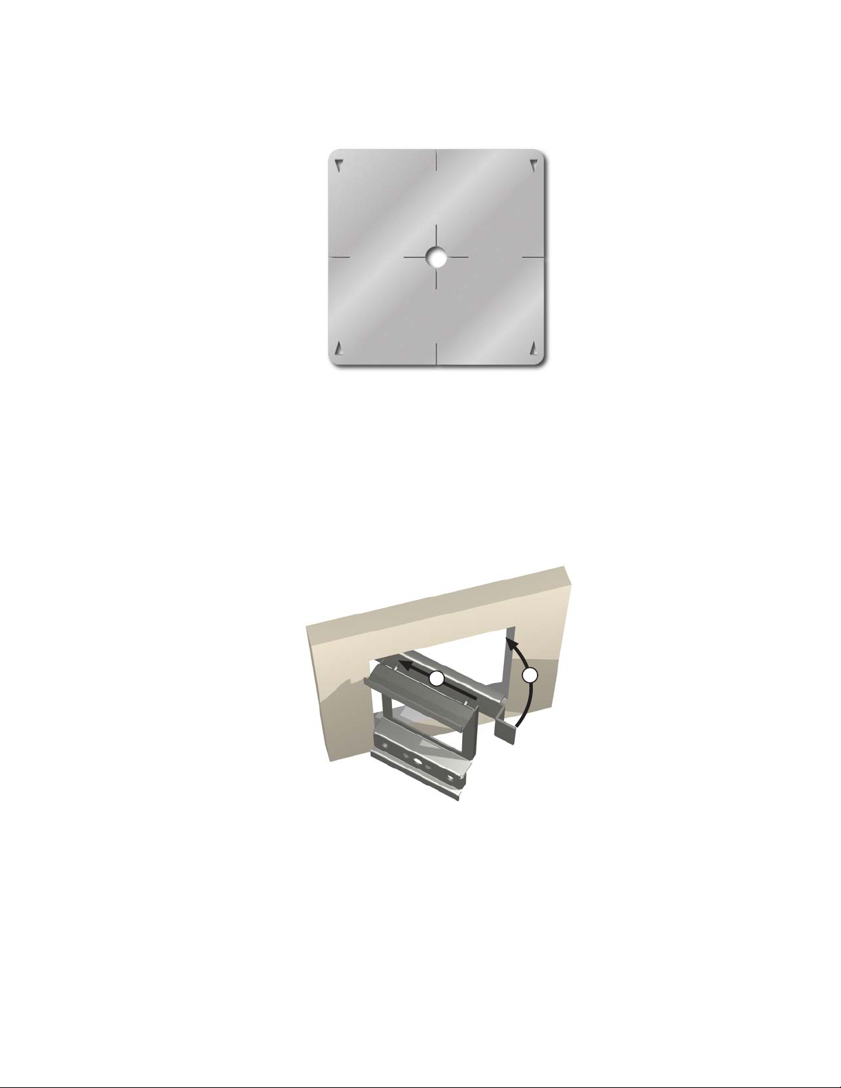
b. Using a level, make proper horizontal and vertical marks on surface to be cut, to properly orient
template.
Figure 7 – MRC88m Keypad mounting template
c. Locate the provided template so that the mark is in the center of the hole, which is in the center of the
template.
d. Rotate the template around the center until the template is level.
e. Press or hammer the template in place so that the holding tabs pierce the wall and hold the template in
place.
f. Mark or scribe the outline of the template on the wall.
g. Remove the template and cut a clean hole through the wall along the outline of the template, being sure
that your cut is on the outline. Any cut outside of the outline by more than ¼” may not be covered by the
MRC88m Keypad.
1
2
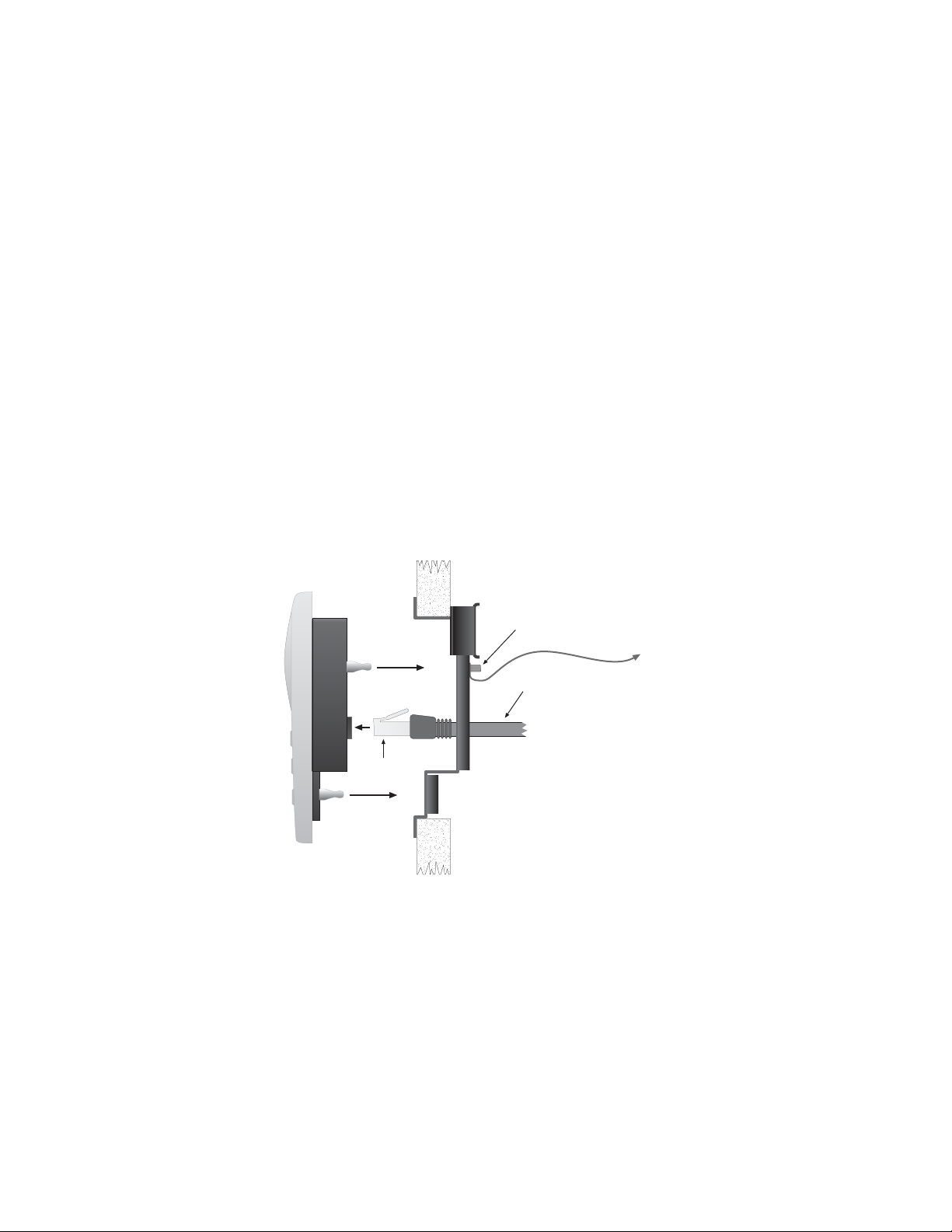
Figure 8 – Installing the MRC88m Keypad mounting bracket in the wall
2. Installing the Mounting Bracket
a. Attach the ground wire to the ground lug to the rear of the back-bar with the provided green nut, before
beginning the bracket installation process.
NOTE: A ground wire connected to Earth ground is required to protect against static di scharge.
b. Orient the Mounting Bracket so the ground lug is on the top portion of the bracket and run the supplied
screws through the top front of the mounting bracket into the back-bar as shown in Figure 6.
Note: Do not tighten screws.
c. Pull the CAT5 cable through the hole in the wall.
d. Pull the CAT5 cable through the hole in the mounting bracket.
© 2009 Xantech Corporation
Page 24
Page: 24 Model MRC88m / MRAUDIO8x8m
e. Slide the left or right side of the back-bar into the wall as shown in Figure 8.
f. Center the mounting bracket in the wall and tighten the screws until the bracket is firmly held in the wall.
Over tightening will distort the bracket and prevent the Keypad from snapping tight against the wall.
Under tightening will cause the Keypad to be loose against the wall.
g. If there is not enough room to slide the keypad in as described above, you can hold the back-bar in
place as you run the screws through the mounting plate and into the back-bar. TIE A LONG STRING
TO THE BACK-BAR so that you can easily retrieve it in case you drop the back-bar into the wall!
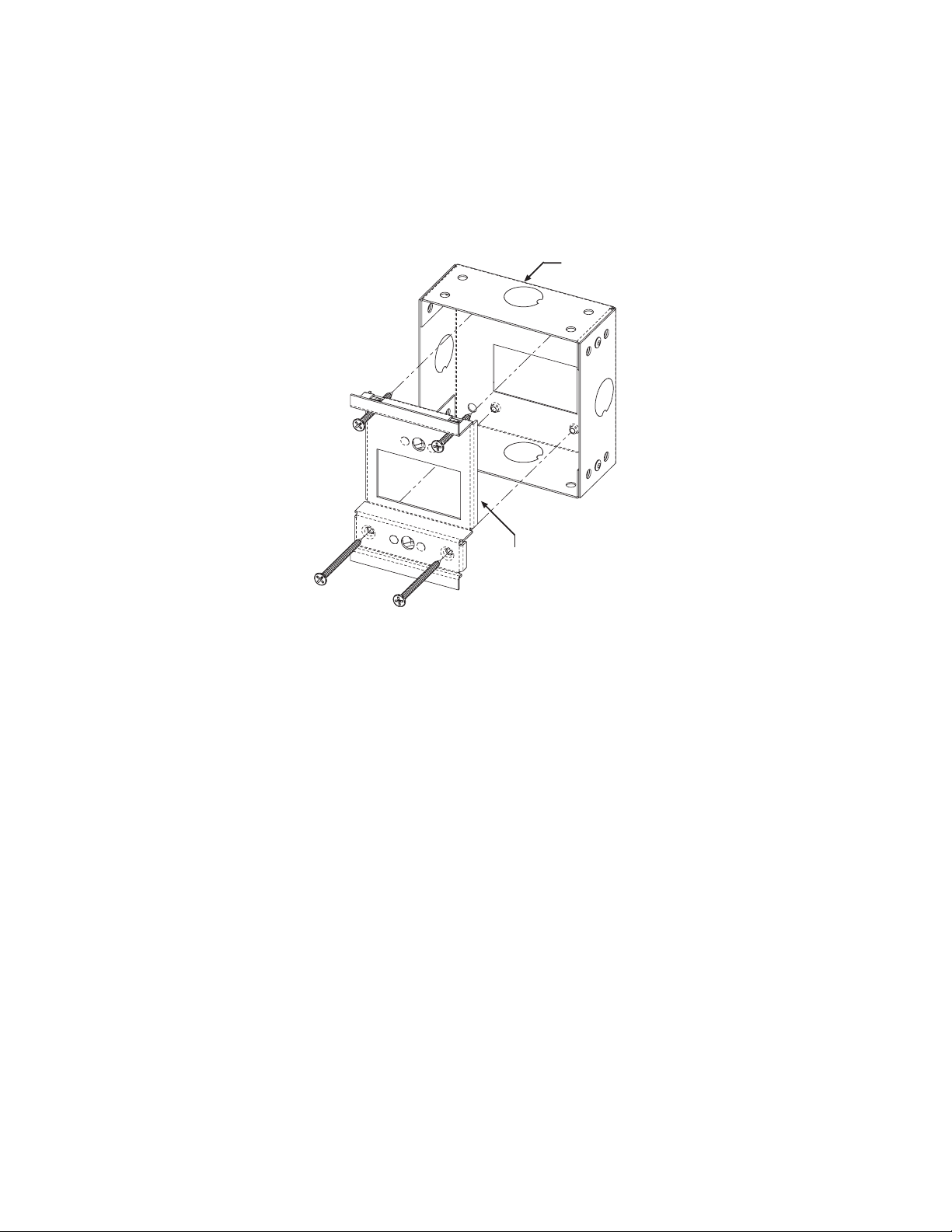
MRCBOX
MRC88 Keypad Mounting Bracket
Figure 8B: Optional Keypad Back-Box for pre-install applications
2-1. MRCBOX (Back-Box) Installation (optional)
a. Position Back-Box so inner rectangle is in a horizontal position. as shown in Figure 8B
b. Affix MRCBOX to Wall Stud at desired height with front of box flush with front of stud (or set back
slightly) as to not interfere with Sheetrock.
c. Attach ground wire to ground lug as described in Step 2a as shown above.
d. Orient the Mounting Bracket so the ground lug is on the top portion of the bracket and using two 1.5”
(38.1mm) self-tapping drywall screws (or sheet metal screws), mount the bracket to the Back Box. For
extra rigidity use two 2” (50.8mm) self-tapping drywall screws (or sheet metal screws) through the
bottom two screw holes.
3. With the Controller/Amplifier turned off, connect the CAT5 cable to the appropriate RJ45 connector, using
Figure 10 as a guide for CAT5 termination.
4. Add or remove jumpers on the rear of the MRC88m keypad-according to Table 1 (Keypad connections).
5. Firmly snap the MRC88m Keypad into the bracket that you have just installed (see Figure 6).
6. Confirm all Keypad operations.
MRC88M KEYPAD REMOVAL
© 2009 Xantech Corporation
Page 25
Model MRC88m / MRAUDIO8x8m Page: 25
POWER
CH
STATUS
SELECT
PLAY
REW
1
2
CH
VOL
PAUSE
VOL
FF
STOP
MUTE
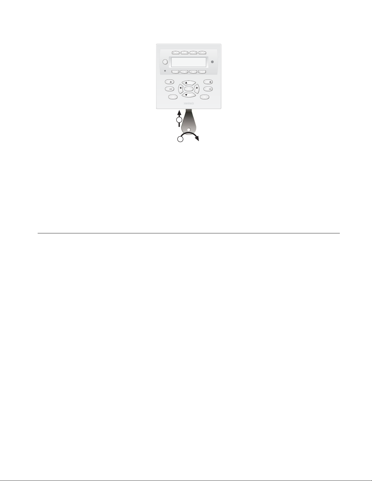
Figure 9 – Removing the MRC88m Keypad from the wall
1. Insert the MRC88m keypad removal tool into the slot at the bottom of the keypad, as shown in Figure 9,
being sure that the tool is inserted so that the “insert to here” line slides under the Keypad. This will reduce
the risk of damage to the Keypad or the wall.
2. Twist the removal tool in either direction until the bottom of the Keypad pulls away from the wall, then
carefully grip the edges of the Keypad with your fingers and pull it off the wall.
NOTE: Since the Keypad snaps into the mounting bracket and there are a large variety of wall textures, the
Keypad may POP OUT or require some additional effort to pull it off the wall, depending on your particular
installation.
CONNECTING THE MRC88m CONTROLLER/AMPLIFIER
When making connections to the MRC88m Controller be sure the power cord is unplugged. Proceed as
follows, referring to Figure 3 and Figure 13 for a typical MRC88m system layout and interconnections:
SOURCE RELATED CONNECTIONS
The following relates to all source related connections to the MRC88m Controller Unit (A/V In/Out, IR Control,
Sense Inputs etc.)
S
OURCE COMPONENT CONNECTIONS
Audio Connections
(BASIC/ADVANCED)
Using good quality RCA-type patch cables connect the LEFT and RIGHT OUTPUT jacks of the source
component (DVD, CD, Satellite receiver, etc.) to the appropriate source AUDIO LEFT and AUDIO RIGHT
INPUT jacks on the MRC88m - Figure 3-(22).. Do this for each source component.
(EXPANDED)
Using good quality RCA-type patch cables connect the source AUDIO LEFT and AUDIO RIGHT OUTPUT
Jacks of the ‘Primary Controller’ - Figure 3-(23). to the corresponding source AUDIO LEFT and AUDIO
RIGHT INPUT jacks on the ‘Secondary Controller’ - Figure 3-(22).
Video Connections (MRC88m Only)
(BASIC/ADVANCED)
Using good quality RCA-type video patch cables connect the VIDEO OUTPUT jacks of the source component
to the VIDEO INPUT jacks on the MRC88m - Figure 3-(22). Do this for each source Component.
(EXPANDED)
Using good quality RCA-type patch cables connect the source VIDEO OUTPUT jacks of the ‘Primary
controller’ [Figure 3-(23)] to the corresponding so urce VIDEO INPUT jacks on the Secondary Controller Figure 3-(22).
© 2009 Xantech Corporation
Page 26

Page: 26 Model MRC88m / MRAUDIO8x8m
ONE AUDIO INPUTS
Z
(ADVANCED)
Use 3.5mm Stereo Mini Jack to Stereo RCA Plug adapter to connect Zone Specific Audio Sources (i.e.
Audio Server or other Zone Specific Audio Component – i.e. MP3 player located in Bedroom 1) to the
appropriate Zone Audio Input - Figure 3-(24). The 3.5mm Stereo Jack is wired as follows: Tip = Right Audio
Input; Ring = Left Audio Input; Sleeve = GND. The Zone Audio Input feature is enabled via Dragon DropIR™ software in the ADVANCED configuration only. When enabled, the Zone Audio Input will override the
Source 1 Input connected at the Audio Left/Right RCA Input terminals - Figure 3-(22). Zone Audio Inputs
do not support Video.
(EXPANDED)
For Zones 1-8, connect to the Primary Controllers Zone Audio Input as stated above. For Zones 9-16
connect to the Secondary Controllers Zone Audio Input [Figure 3-(24)] as stated above.
IR
CONTROL CONNECTIONS
(BASIC/ADVANCED)
Plug the supplied 283M IR emitters into the appropriate IR Emitter jacks - Figure 3-(26). Be careful to
match the source audio and video connection number on the MRC88m to the IR Emitter jack number. This
will ensure that the IR control signal will be routed to the correct source component. Find the IR sensor
window on the source component and attach the emitter to the components sensor window after removing
the protective paper cover on the flat side of the emitter head. A Common IR jack is also provided for
connection to other auxiliary devices that are not source specific - Figure 3-(27).
(EXPANDED)
Connect emitters to the ‘Primary Controllers’ IR Emitter jacks - Figure 3-(26) as noted above.
Note: The appropriate source IR Emitter of the ‘Secondary Controller’ will also flash regardless of what
zones keypad issues the command but it is recommended to use the emitter jacks of the Primary unit.
S
ENSE INPUT CONNECTIONS
(BASIC/ADVANCED)
The sense input connection will typically be used to sense the power state of a source component using the
Xantech CSM1 Current Sense Module (optional). Plug the 3.5mm mini plug from the CSM1 into the
appropriate sense jack – Figure 3-(22). Be careful to match the source audio and video connection number
on the MRC88m to the appropriate sense jack number. The CSM1 plugs into an AC power source. The
component power cord plugs into the CSM1. (Refer to instructions included with the CSM1 unit).
CSM1 Threshold Adjustments
a. First, make sure the 3.5mm mini-plug is plugged into the appropriate sense jack on the MRC44 and that
the MRC44 is powered ON. (The CSM1 gets low-voltage DC power from the MRC44 – not from the AC
line. See Figure 2-Top for mini-jack pin out )
b. Select the correct position of the RANGE slider switch – the HI position is for devices with a high
current draw when ON, the LO position is for devices with a low current draw when ON (based upon the
lowest current draw state of the component when ON).
c. Manually turn the component ON.
d. Using a small (1/8” wide) blade screwdriver, rotate the current control to the full CLOCKWISE position
(LO CURRENT).
e. Rotate the control COUNTER-CLOCKWISE (towards the HI CURRENT position) until the Threshold
Adjustment LED goes OFF.
f. Turn the component OFF (Standby Mode).
g. Rotate the control CLOCKWISE until the Threshold Adjustment just goes ON.
h. Set the control to a point midway between these two settings. This should be the correct setting.
NOTE 1: If you have trouble with the threshold adjustment correctly detecting the ON and OFF states of
the component, try changing the RANGE slider to the opposite position and then try the adjustment again.
NOTE 2: If the Threshold Adjustment LED does not go ON and OFF with the component power, make
minor adjustments to the threshold adjust until the LED is in proper sync.
NOTE 3: Program IR commands for the MRC44 Controller current sensing as d escribed in the MRC44
Installation Instructions, “PROGRAMMING SENSE CODES”.
© 2009 Xantech Corporation
Page 27

Model MRC88m / MRAUDIO8x8m Page: 27
(EXPANDED)
Connect CSM1’s as described above to the Primary Controller. Sense inputs are not available on the
Secondary Controller.
ZONE RELATED WIRING CONNECTIONS
In typical applications, each zone will have at least one MRC88m Keypad and a pair of stereo speakers. In
those zones with both audio and video, at least one video monitor or television will also be used. In order to
make these connections, the minimum requirement is home runs of one CAT5 cable for each zone’s
keypad(s), two pairs of 12-18AWG wire for each pair of speakers, and one coaxial cable for a TV or monitor
from each zone to the MRC88m Controller/Amplifier location.
S
PEAKER CONNECTIONS
(BASIC/ADVANCED/EXPANDED)
1. Using good quality speaker wire, connect the individual speaker leads to the 4-terminal "SPEAKER"
connectors on the MRC88m as shown in Figure 3-(22).
2. The MRC88m Speaker Terminals (amplifier outputs) are 4-Ohm safe. Make sure the combined
impedance presented to the speaker terminals by the speakers (or any combination of speakers) is 4Ohm minimum.
3. Be sure to observe correct polarity by connecting the "+" and "–" terminal from each channel on the
MRC88m to the corresponding "+" and "–" terminals on each speaker. This will ensure proper
"phasing" (See Step 6). Since the connectors are removable, you may unplug them for ease of lead
assembly.
4. As a rule of thumb, use 18 gauge speaker wire for speaker runs up to 30' (9m), 16 gauge up to 70'
(21m), and 14 gauge up to 150' (39m). The 4-terminal connectors accept wire sizes up to 12-gauge
max.
5. Strip the insulation back about 1/4" (6mm) and twist the strands on each lead to prevent fraying.
6. Speaker Phasing: To obtain stable imaging and full bass response, it is imperative that stereo
speakers be connected "in phase" with each other. You can verify this as follows:
a) If the "+" (positive) and "–" (negative) terminals on your speakers are correctly marked, and visible,
and you have wired the system with the positive connector on the rear of the MRC88m
Controller/Amplifier connected to the positive connector on the speaker and the negative connector
on the rear of the MRC88m Controller/Amplifier connected to the negative connector on the
speaker, then the system will be "in phase". No further action is required. Most manufacturers
identify the positive terminal with a red binding post, a "+" sign, or a red dot.
b) If you are unsure of the markings, you can verify the phasing. Using a mono sound source, such as
AM radio, alternately reverse the leads to one of the speakers. Pick the connection that delivers a
solid center image between the speakers as well as best bass resp onse.
CAUTION: After lead ends are inserted and the screws tightened down, be sure there are no free
strands that could cause shorting!
© 2009 Xantech Corporation
Page 28
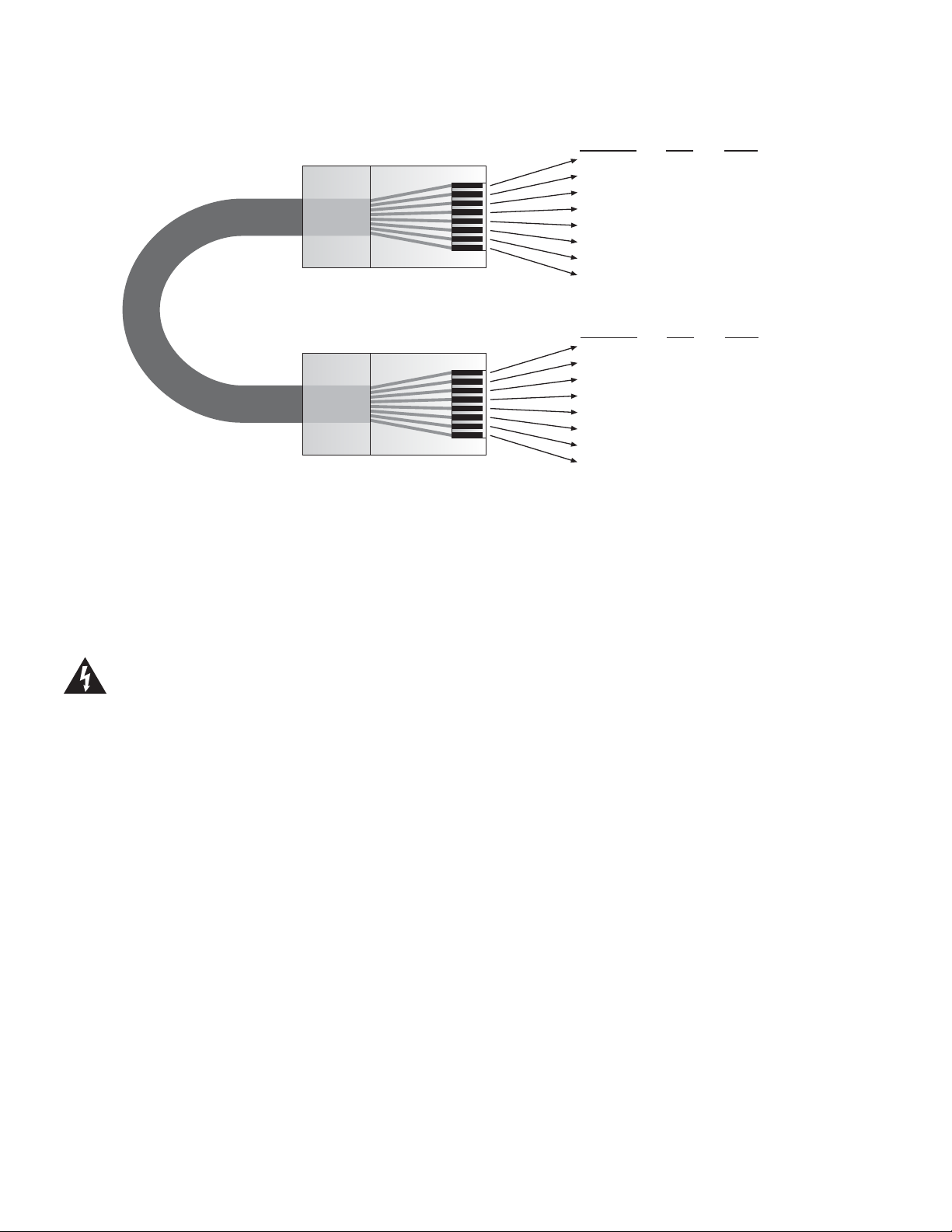
Page: 28 Model MRC88m / MRAUDIO8x8m
RJ45 Connector at
Controller/Amplifier
Wire Color Pin # Signal
white/orange 1 485 +
orange 2 485 white/green 3 12V RET
blue 4 IR RET
white/blue 5 IR
green 6 +12V
white/brown 7 Attn. 485
brown 8 IR Loop Back
Cat 5
Cable
Figure 10 - CAT5 Pin Assignments (per EIA/TIA 568B) Pinned 1:1
MRC88
(BASIC/ADVANCED/EXPANDED)
The MRC88m ‘Pin-to-Pin’ CAT5 cabling that can be purchased pre-fabricated at fixed lengths or self-assembled
to custom lengths. The color-coded wiring standard is EIA/TIA 568B as shown in Figure 10. The plastic
connector on the end of the CAT5 wire is “registered jack” RJ45.
1. See Figure 10 for proper termination of the CAT5 cables to the RJ45 connectors.
2. Connect the zone keypad to the appropriate zone Keypad connector on the rear of the MRC88m
V
(BASIC/ADVANCED/EXPANDED)
Composite Video
1. When running composite video to a TV or monitor, use RG-6 coaxial or RG-59 quadshield cable with
Modulated Video
3. When modulating the zone video output and using the RF/ANT input to a television, connect the VIDEO
S
M KEYPAD CAT5 CABLE CONNECTIONS AT THE MRC88M CONTROLLER/AMPLIFIER
Controller/Amplifier – Figure 3-(16).
Caution:
the MRC Keypad! Be sure to test cable for proper connections before making connections.
IDEO CONNECTIONS (MRC88M ONLY)
Power voltage for the keypad is transmitted along this cable! Incorrect wiring on this cable can d estroy
RCA type phono plugs on each end. This connection can be run up to 150 feet, as this is a buffered
video output from the MRC88m Controller/Amplifier.
2. Connect the zone video cable to the appropriate zone video jack on the rear of the MRC88m Controller/
Amplifier – Figure 3-(18).
OUTPUT from the MRC88m Controller – Figure 3-(18), to the VIDEO INPUT of a Modulator, using high
quality RCA type video patch cords. Use RG-6 coaxial cable with "F" connectors on each end to
connect the Modulator, to the RF/ANT IN on the room TV.
TATUS CONNECTIONS AND COMMON CONTROL OUT
Status
(BASIC/ADVANCED/EXPANDED)
Each zone has a Status Output –Figure 3-(19), that provides a control output of +12 VDC, 50mA that turns
ON and OFF with the zone ON/OFF condition. ON = +12VDC, OFF = 0VDC. Using a 3.5mm mono mini
phone connector, this control can be used to close a relay, such as a Xantech CC12, to raise a TV lift or
drop a projection screen automatically when a zone is turned ON. Connect one end of the 3.5mm Mono
RJ45 Connector
at Keypad
Wire Color Pin # Signal
white/orange 1 485 +
orange 2 485 white/green 3 12V RET
blue 4 IR RET
white/blue 5 IR
green 6 +12V
white/brown 7 Attn. 485
brown 8 IR Loop Back
© 2009 Xantech Corporation
Page 29

Model MRC88m / MRAUDIO8x8m Page: 29
Mini jack to the appropriate zone Status connector on the rear of the MRC88m Controller/Amplifier and the
other end to the device to control. Tip=Control Voltage; Sleeve=GND
Control Out
(BASIC/ADVANCED)
A single Common Control Output is provided on the rear of the MRC88m Controller/Amplifier –Figure 3(20). When the Common Control Output is High (+12 volts, 50 mA), this indicates that ‘at least’ one zone is
powered ON. When the Common Control Output is Low (0 volts), this indicates that ‘all’ zones are OFF.
Using a 3.5mm mono mini phone connector, this control can be us ed to close relays (Xantech CC12) or
turn on an AC outlet (Xantech AC1, AC2) for activity common to the system. Connect one end of the 3.5mm
Mono Mini jack and the other end to the device to control. Tip=Control Voltage; Sleeve=GND
(EXPANDED)
When at least one zone on either the PRIMARY or SECONDARY controller is turned ON, the Control Out
on the PRIMARY Controller is High (+12VDC). The Control Out on the SECONDARY Controller is inactive
in EXPANDED mode.
P
REAMP OUT
(BASIC/ADVANCED/EXPANDED)
Each zone has a Prea mp Out to send ‘zone selected’ audio to another amplifier such as the Xantech
PA435x or PA4100x. This may be desired for feeding a sub-zone on a separate amplifier, zones that
require more than 35W, or for sending audio to another amplifier with Dolby™ surround deco ding for
‘theater quality’ audio in the zone.
Using go od quality RCA-type patch cables, connect the Preamp Out, Left(L) and Right(R) connectors –
Figure 3-(25), to the desired external amplifiers Audio Left and Right Input connectors.
CO1
AND CO2 (ZONES 7 & 8)
(BASIC/ADVANCED/EXPANDED)
Zones 7 and 8 have a Remote Mute/Standby output for interfacing and controlling a Xantech PA435X
(included) or PA4100X amplifier. The control is provided via a Stereo Mini Jack with the TIP controlling
STANDBY logic (Standby Power On = +12 volts, Standby Power Off = 0 volts) and the RING controlling
MUTE logic (Mute = +12 volts, Un-Mute = 0 volts).
Using a 3.5m m Stereo Mini Jack to 3.5mm Stereo Mini Jack cable, plug one end into the CO1 (or CO2)
output jack on the rear of the MRC88m Controller/Amplifier – Figure 3-(21) and the other end into the
corresponding jack labeled CO1 (or CO2) on the PA435X or PA4100X amplifier.
NOTE: Be sure to set the Control In (CI) switch to ON located on the rear of the PA435X or PA4100X
amplifier.
Z
ONE IR
(BASIC/ADVANCED/EXPANDED)
Using Xantec h Emitters (282M, 283M,284M, or 286M), plug the 3.5mm Mono Mini jack into the appropriate
zones Zone IR connector – Figure 3-(28). Affix the mouse emitter side to the desired zone related
component you wish to control. If more than one device needs to be controlled, use a mono mini to
stripped-ends wire (PN#6015900) wired to a Xantech 791-44 Amplified Connecting block. Any IR generated
in the zone (either from MRC-88 Keypad, IR received at the Keypad, or routed from another zone
(ADVANCED only)) will be passed to this emitter port.
AC
POWER CONNECTIONS
(BASIC/ADVANCED/EXPANDED)
Use the supplied power cable and plug into a power source capable of delivering the rated amps shown in
the specification section of this manual.
© 2009 Xantech Corporation
Page 30
Page: 30 Model MRC88m / MRAUDIO8x8m
CONNECTIONS AT THE ZONE LOCATION
(BASIC/ADVANCED/EXPANDED)
K
EYPAD CONNECTIONS AND JUMPER SETTINGS
Single Keypad CAT5 Connections
1. Refer to Figure 10 for proper termination at the zone-end of the CAT5 cable.
2. Set Keypad Address jumper configuration on the rear of the keypad – Figure 5-(17) according to Table
1 below.
2. Connect the CAT5 cable from the MRC88m Controller/Amplifier into the RJ45 jack marked “Controller”
on the rear of the MRC88m keypad.
Caution:
destroy the MRC Keypad! Be sure to test cable for proper connections before making connections.
Power voltage for the keypad is transmitted along this cable! Incorrect wiring on this cable can
Multiple Keypad Connections
1. For a second keypad in the same zone, terminate the CAT5 cable in the same way as shown in Figure
10.
2. Connect the CAT5 coming from the MRC88m Controller to the “CONTROLLER” jack on the Primary
Keypad. Plug a CAT5 cable into the “EXPANSION” jack on the Primary Keypad and connect it to the
“CONTROLLER” jack on the Secondary Keypad. Repeat for all keypads in zone (up to a total of 4
Keypads) Set the Address jumpers on the rear of the keypad – Figure 5-(17) according to Table 1
below.
Keypad Address Setting
Application
JP1 JP2
First (or Single) Keypad in Zone
(Primary Keypad connected
directly to MRC88m
OFF OFF
Controller)
Second Keypad in Zone
(Connected to Primary
OFF ON
keypads Expansion Port)
Third Keypad in Zone
(Connected to Second
ON OFF
keypads Expansion Port)
Fourth Keypad in zone
(Connected to third keypads
ON ON
Expansion Port)
Table 1 – MRC88m Keypad Address Settings
Zone Termination
The LAST keypad connected in the zone (Keypad with no other keypad plugged into its EXPANSION
port) must have the Zone Termination Jumper installed – Figure 5-(18).
Sensor Enable
To disable the Keypads on-board IR Receiver, remove the Sensor Enable jumper on the rear of the
keypad – Figure 5-(19).
External IR Terminal Block
To conveniently add other Xantech IR Receivers or Keypads (SMARTPAD or WATERPAD) in
conjunction with the MRC88m Keypads, you may wire 18AWG-24AWG 4-conductor wire, directly to the
terminal block on the rear of the Keypad – Figure 5-(23). A 4-conductor screw-type removable
connector is provided to safely wire the +12v, STATUS, IR IN and GND to the rear of the Keypad. This
might be useful when adding a Plasma Friendly (or other) IR Receiver (490-90 etc.) or adding a sub zone keypad either outdoors or in a bathroom (WATERPAD Keypad).
© 2009 Xantech Corporation
Page 31

Model MRC88m / MRAUDIO8x8m Page: 31
Note: The 12VDC output terminal is rated at 100mA and can power up to one
SMARTPAD/WATERPAD Keypad or up to 4 IR Receivers. Anymore then this will require the use of an
external power supply. Do not wire the external power supply to the MRC8 8m keypad. Wire
directly to the units to be powered.
The STATUS line is an output and is active Hi (+12VDC) when the MRC88m Keypad is po wered ON
and is LOW (0VDC) when the Keypad is OFF. Use this to provide Bank Tracking LED on the
SMARTPAD/WATERPAD keypad or other.
In Zone IR
To wire local emitters in-the-zone (emitters used to control components in the same general area as the
keypad), wire the IR OUT and GND terminals on the rear of the MRC88m Keypad –Figure 5-(22) to the
IR (white stripe) and GND of the emitter cable. To control numerous components in the same area, wire
these terminals to an amplified connecting block (Xantech 791-44) using 18-20AWG 2-conductor cable.
A 2-conductor screw-type removable connector is provided.
ZONE EXPANSION (CONNECTING TWO MRC88M CONTROLLERS)
(EXPANDED)
For systems greater than 8 Zones, two MRC88m Controller/Amplifiers can be linked together for systems up to
16 Zones. Zone expansion is only available in Advanced programming configurations.
L
INKING TWO MRC88M CONTROLLER/AMPLIFIER UNITS
To connect two systems, simply connect the supplied DB15 Expansion Cable to the EXPANSION Port on the
rear of one unit to the EXPANSION Port on the other – Figure 3-(30). These units should be placed either side
by side or if installed in a 19” (483mm) equipment rack, leave 2 rack unit spaces (2U space) between the two
units [One Rack Unit space = 1-3/4” (44.5mm) in height].
CAUTION: Do not place these units directly on top of each other. This may cause damage to the units
due to increased heat dissipation.
C
ONNECTING SOURCE COMPONENTS
When connecting two units together, designate one unit as the PRIMARY Unit (Zones 1-8) and the other unit as
the SECONDARY Unit (Zones 9-16). All source components should be connected directly to the PRIMARY
Units Source A/V Inputs – Figure 3-(22). Use the PRIMARY Units Audio and Video Loop-Thru connectors –
Figure 3-(23) to feed the source component inputs of the SECONDARY Unit – Figure 3-(22).
All of the source components emitters should be connected to the PRIMARY Units IR Emitter Output Ports –
Figure 3-(26). This rule applies to the SENSE INPUTS also.
© 2009 Xantech Corporation
Page 32

Page: 32 Model MRC88m / MRAUDIO8x8m
Extended Runs and Secondary Keypads In Zone
A
500 feet max (152 m)
POWER
CH
CH
IR Receiver
VOL
PAUSE
SELECT
VOL
PLAY
FF
REW
STOP
STATUS
MUTE
B
POWER
VOL
CH
PAUSE
SELECT
VOL
CH
PLAY
FF
REW
STOP
STATUS
MUTE
POWER
CH
CH
STATUS
IR Receiver
VOL
PAUSE
SELECT
VOL
PLAY
FF
REW
STOP
MUTE
250 feet max (76 m)
C
POWER
VOL
CH
PAUSE
SELECT
VOL
CH
PLAY
FF
REW
STOP
STATUS
MUTE
POWER
CH
PAUSE
SELECT
CH
PLAY
FF
REW
STOP
STATUS
MUTE
POWER
VOL
VOL
VOL
CH
PAUSE
SELECT
VOL
CH
PLAY
FF
REW
STOP
STATUS
MUTE
POWER
CH
CH
IR Receiver
VOL
PAUSE
SELECT
VOL
PLAY
FF
REW
STOP
STATUS
MUTE
125 feet max (38 m)
780-80
CFL / DIRECT SUNLIGHT
FRIENDLY IR RECEIVER
WPK8
WATERPAD
CD
TUNER
CH
CH
CATV
SAT
DISC
LD
DVD
VOL
VOL
MUTE
OFF
VCR
TAPE
D
782-00
Power Supply
(OPT)
IR RCVR
PWR
VGS
MRC44
Connecting
Block
250 feet max (76 m)
490-90
PLASMA-FRIENDLY
MICRO LINK
Figure 11 – MRC88m Keypad CAT5 Cable Lengths
The maximum cable length for CAT5 connections to a single keypad is 500 feet (see Figure 11-A). For two
keypads in a zone, the distance to the last keypad is cut in half to 250 feet (see Figure 11-B). This same
relationship applies to systems with 4 Keypads in the zone (Max distance to last keypad is 125ft.).
Figure 12:
MRC88m Connecting Block located on rear of Keypad
© 2009 Xantech Corporation
Page 33

Model MRC88m / MRAUDIO8x8m Page: 33
If any keypad in the zone is using an external IR receiver, or if an outdoor keypad is necessary in a subzone, the MRC88m Terminal Block on the rear of the keypad (see Figure 12) can be used to expand the
connections on the back of the keypad as shown in Figures 11A, B, & C. The Maximum cable run to the
external IR receiver/keypad in each of the above cases can be up to 125 feet from the keypad depending
upon type and gauge of wire used.
Note: If no MRC88 Keypad will be used in a particular zone, IR Receivers and/or IR based Keypads may
be used as shown in Figure 11D using the MRC44CB1 Connecting Block. This will be desired for:
1. Zones with IR Receiver ONLY
2. Outdoor Zone where WaterPad Keypad and/or IR Receiver is needed
The MRC44CB1 connecting block can be used as shown in Figure 11D above. Using a CAT5 wire, conn ect
one end into the desired Zone output of the MRC88m controller and connect the other end to the RJ45
connector labeled CONTROLLER on the MRC44CB1 connecting block. IR Receivers terminated with a
Stereo Mini Jack may directly connect to the MRC44CB1 connector labeled IR IN. For all others IR Recv’s
with bare wire or Keypads) use 24AWG or higher and connect using the +12v, GND, and SIG screw
terminals. A separate power supply is required for configurations in which the current load will exceed
85mA. Consult the MRC44CB1 manual for complete instructions.
S
PEAKER CONNECTIONS
(BASIC/ADVANCED/EXPANDED)
SPEAKER PHASING: TO OBTAIN STABLE IMAGING AND FULL BASS RESPONSE, IT IS IMPERATIVE
THAT STEREO SPEAKERS BE CONNECTED "IN PHASE" WITH EACH OTHER. YOU CAN VERIFY THIS
AS FOLLOWS:
1. If the "+" (positive) and "–" (negative) terminals on your speakers are correctly marked, and visible, and you
have wired the system with the positive speaker connector on the rear of the MRC88m Controller/Amplifier
connected to the positive connector on the speaker and the negative speaker connector on the rear of the
MRC88m Controller/Amplifier connected to the negative connector on the speaker, then the system will be
"in phase". No further action is required. Most manufacturers identify the positive terminal with a red
binding post, a "+" sign, or a red dot.
2. If you are unsure of the markings, you can verify the phasing. Using a mono sound source, such as AM
radio, alternately reverse the leads to one of the speakers. Pick the connection that delivers a solid center
image between the speakers as well as best bass response.
CAUTION: After lead ends are inserted and the screws tightened down, be sure there are no free strands
that could cause shorting!
V
IDEO CONNECTIONS
(BASIC/ADVANCED/EXPANDED)
Composite Video
The buffered, composite video output from the MRC88m Controller/Amplifier will drive a VIDEO INPUT on a
TV or monitor directly. Use RG-6 coaxial or RG-59 quadshield cable with RCA type phono plugs on each
end. This connection can be run for 100 feet.
Modulated Video
When using the RF/ANT input on a television, use RG-6 coaxial or RG-59 quadshield cable with "F"
connectors on each end to connect to the RF output on the Modulator to the RF/ANT in on the zone TV.
© 2009 Xantech Corporation
Page 34

Page: 34 Model MRC88m / MRAUDIO8x8m
SETTING-UP THE MRC88m SYSTEM
(BASIC/ADVANCED)
To better demonstrate the ease and versatility of programming the MRC88m, Figure 13 will be used to illustrate
setup for a typical application.
(EXPANDED)
For setup of an expanded system, see Figure 24.
The MRC88m is programmed using the included Xantech Dragon Drop-IR™ program, Drag450MRC and
connection accessories. For additional information, please call Xantech technical support at 1-800-843-546 5 ext
812 or visit http://www.xantech.com Ref: Products, IR Code Libraries, Software.
A/V Source 1
A/V Source 8
To MRC88
Controller/Amplifier IR Outs
MRC88 Controller/Amplifier
AUDIO OUT
ZONE 1
VIDEO OUT
ZONE 1
AUDIO OUT
ZONE 2
VIDEO OUT
AUDIO OUT
ZONE 2
ZONES 1 - 6
TV
Primary Keypad Secondary Keypad
POWER
CH
CH
REW
STATUS
POWER
VOL
PAUSE
SELECT
PLAY
STOP
CH
PAUSE
VOL
FF
MUTE
SELECT
CH
PLAY
REW
STOP
STATUS
ZONE 3
VOL
VOL
FF
MUTE
VIDEO OUT
ZONE 3
AUDIO OUT
ZONE 4
VIDEO OUT
ZONE 4
PA435X 35 Watt
Four-Channel
Power Amplifier
AUDIO OUT
ZONE 5
VIDEO OUT
ZONE 5
To MRC88
Controller/Amplifier IR Outs
AUDIO OUT
ZONE 6
VIDEO OUT
ZONE 6
AUDIO OUT
ZONE 7
VIDEO OUT
ZONE 7
AUDIO OUT
ZONE 8
ZONES 7 & 8
VIDEO OUT
ZONE 8
To IR Emitters
at A/V
Equipment
Hand Held
Remote
TV
Secondary Keypad Primary Keypad
POWER
CH
CH
REW
STATUS
Hand Held
VOL
PAUSE
SELECT
VOL
PLAY
FF
STOP
MUTE
Remote
POWER
CH
PAUSE
SELECT
CH
PLAY
FF
REW
STOP
STATUS
VOL
VOL
MUTE
Figure 13 –Typical MRC88m System
© 2009 Xantech Corporation
Page 35

Model MRC88m / MRAUDIO8x8m Page: 35
Section 3: Pre-Programming the MRC88m
Programming the MRC88m system involves planning the system and most of all, programming the system. This
section is broken down to walk you through from Basic to Advanced modes of programming as well as
programming external Universal IR Remotes (Xantech URC-2 or other) to control the MRC88m
Controller/Amplifier.
Through Dragon Drop-IR™ Software, you will configure all of the Keypads placing IR Commands und er the
function buttons to control the MRC88m Controller/Amplifier as well as the A/V Source components connect ed
to the Controllers. You will also setup the unit to provide Power Management for all of the source components
assuring no individual source will be out of sequence allowing all items to operate as one seamless system. All
other ADVANCED features are also programmed here including Zone Linking, Monitor Lockout, RS232 control,
and IR Routing of received commands (to name a few).
The actual keypads are not programmed in the system. All keypad functionality is contained in the MRC88m
Controller/Amplifier. Each keypad access’s its functions via bi-directional communications between the keypad
and the controller. This means the system is programmed ‘as a whole’ which saves programming time and
ease of maintenance. Keypads can be interchanged or replaced without any further programming!
A system programmed under BASIC mode will allow for the following features to be utilized:
1. Basic Controller/Amplifier control including: Zone Power On/Off, Source Selection, Speaker
Volume, Speaker Mute, Speaker Balance control, EQ Treble/Bass adjustment from the keypad,
2. Basic IR Control of all source components from the keypad function buttons as well as via the
Keypads built-in IR Receiver.
3. Source Power Management (Video or Current Sense) for each source connected.
4. Icon Editor
A system programmed under ADVANCED mode will allow for the following additional features to be utilized:
1. All BASIC features listed above
2. EXPANDED operation mode (systems with 2 Controller/Amplifiers)
3. RS232 Control of external components from the keypad
4. RS232 Control of the MRC88m Controller/Amplifier from external devices such as PC’s, Touch
Screen Controllers or any other RS232 device
5. Programming of Internal Amplifier Commands
6. Static and Dynamic Linking of Zones
7. Priority Lockout Enable/Disable as well as Monitor Lockout
8. IR Routing Enable/Disable
9. Use of Zone Audio Inputs
10. RC68+ IR Macro Generator
11. Configurable LCD backlight time-out settings
© 2009 Xantech Corporation
Page 36

Page: 36 Model MRC88m / MRAUDIO8x8m
PLANNING THE SYSTEM
Before attempting any programming, plan the system configuration first. This should include the following:
1. Determine the brand and type of all source components to be used.
Source 1: ________________________
IR File Name: _____________ IR Library Palette
Source 2: ________________________
IR File Name: _____________ IR Library Palette
Source 3: ________________________
IR File Name: _____________ IR Library Palette
Source 4: ________________________
IR File Name: _____________ IR Library Palette
Zone Audio Source 1: ______________
IR File Name: _____________ IR Library Palette
Zone Audio Source 2: ______________
IR File Name: _____________ IR Library Palette
Zone Audio Source 3: ______________
IR File Name: _____________ IR Library Palette
Zone Audio Source 4: ______________
IR File Name: _____________ IR Library Palette
Source 5: ________________________
IR File Name: _____________ IR Library Palette
Source 6: ________________________
IR File Name: _____________ IR Library Palette
Source 7: ________________________
IR File Name: _____________ IR Library Palette
Source 8: ________________________
IR File Name: _____________ IR Library Palette
Zone Audio Source 5: ______________
IR File Name: _____________ IR Library Palette
Zone Audio Source 6: ______________
IR File Name: _____________ IR Library Palette
Zone Audio Source 7: ______________
IR File Name: _____________ IR Library Palette
Zone Audio Source 8: ______________
IR File Name: _____________
IR Library Palette
CAUTION: See caution card (included) for the latest information regarding code compatibility before
finalizing the system as there may be some IR code incompatibilities.
2. Determine the components to be used in each zone. Some sources may not be available in all zones.
3. Perform the Out-of Box PRE TEST as outlined in Section 2.
4. Assemble the components into a working MRC88m system such as that shown in Figure 13.
5. Decide whether the MRC88m System will be programmed in BASIC, ADVANCED or EXPANDED modes
BASIC MODE ADVANCED MODE EXPANDED MODE
6. Program the MRC88m System using the included version of Dragon Drop-IR™ Software (DRAGMRC).
7. Transfer the System Project to the MRC88m Controller(s).
8. Confirm all functions in all zones.
INSTALLING AND CONFIGURING THE DragMRC SOFTWARE
(BASIC/ADVANCED/EXPANDED)
COMPUTER REQUIREMENTS (MINIMUM)
• Pentium w/32Mb RAM min.
• Windows 98/ME/NT/2000/XP
• 20 MB Hard Drive space (you will need more as your keypad libraries expand)
• 16 MB RAM (32 MB preferred)
• Mouse
© 2009 Xantech Corporation
Page 37

Model MRC88m / MRAUDIO8x8m Page: 37
INCLUDED HARDWARE & SOFTWARE ITEMS
The MRC88m Dragon Drop-IR package includes:
• DragMRC CD ROM
• One DB9 Male-to-Female Cable. Connects the MRC88m COM PORT to a DB9 SERIAL PORT 1 on your
computer. If you need to use serial ports 2, 3 or 4 on your computer, see "SERIAL PORT SELECTION"
section. If your computer only has a USB connection, a USB Type Port is also provided for programming
purposes (requires cable with USB ‘B’ Type connector).
CONNECTING THE MRC88M CONTROLLER/AMPLIFIER TO THE PC
To program the MRC88m Controller/Amplifier, the unit will need to be connected to a PC for programming.
SERIAL CONNECTION
DB9
Connect the supplied DB9 cable to your PC serial port and the other end to the DB9 connector labeled
RS232 COM on the front panel of the MRC88m – Figure 2-(8).
USB
SERIAL CONNECTION
Connect one end of the USB cable (not included) to the USB port of your PC and the other end to the
connector labeled USB COM on the front panel of the MRC88m – Figure 2-(11).
NOTE: The USB connection requires a ‘B’ Type connector to interface with the MRC88m. Connecting a
cable into this port will automatically override any device connected to the RS232 COM port on the front
of the MRC88m
SOFTWARE INSTALLATION
Windows 98/ME/NT/2000/XP
Install the DRAGMRC program onto your hard drive as follows:
1. Insert the disc into your computer’s CD-ROM drive. If your drive has been set for auto run, a Xantech
Welcome Menu will appear. If not, access your CD ROM with Windows Explorer and double click the
file "setup.exe".
2. On the Welcome menu, click NEXT.
3. Follow the on-screen instructions as the program installs. It takes approximately one to three minutes to
complete, depending on the speed of your machine.
NOTE: For the convenience of the installer, the Dragon Drop-IR™ CD-ROM contains a complete set of
Application Notes, the Xantech Product Catalog, Factory Learned IR Codes, web site browse rs Read
the Very Important Notes first, click on the desired menu item and follow the on-screen inst ructions.
STARTING MRC88M DRAGON DROP-IR™ SOFTWARE
Double-click the DragonMRC icon on your desktop or:
1. From START menu, choose Programs.
2. Select Xantech and click on the DragMRC Icon from the menu.
3. The program loads and opens to the Xantech MRC Dragon Drop-IR opening screen.
SERIAL PORT SELECTION
When first launched, the Dragon Drop-IR software scans the serial ports on your computer a nd will display the
available ports under "Preferences" in the File menu. Unavailable ports will be grayed out.
NOTE: If you are using the USB port, see the instructions below on Configuring the USB Port.
To configure the USB Port for the first time, complete the following instructions:
1. Turn the system ON and then turn the PC ON.
2. Connect the USB cable from the PC to the USB connector on the front of the MRC88m Controller.
3. A New Hardware window should appear on the PC. Click NEXT to search the d rive for an available
driver. For File Location point the system to C:\Program Files\DragMRC\USB folder.
© 2009 Xantech Corporation
Page 38

Page: 38 Model MRC88m / MRAUDIO8x8m
4. Click Next to continue.
The proper drivers should now be installed.
Normally you would use Com Port 1 (USB will usually appear as COM 3 or above), but if it is already in use, it
will be necessary to use a different one (use the DB9-to-DB25 adapter if necessary). Select the Com Port as
follows:
1. Click Preferences from the File menu or simply press F2 on your keyboard
2. Click on an available port, then OK.
.
VERIFYING COM PORT COMMUNICATION
(“Who Am I” Base Unit Version Verification)
Before continuing, it is recommended to verify proper COM PORT communication between the PC and the
MRC88m. By checking the units Firmware versions and verifying a response from the MRC88m, you will
confirm proper communication and may continue.
1. Power the Unit ON and allow to boot to steady state (all front staus LED’s OFF)
2. Click on the Base Unit Menu and select Who Am I?
3. This will open a window labeled Base Unit Version Query. Click Next to proceed.
4. This should return a listing of the Base Unit Firmware Version as well as the Keypad Firmware
Versions.
5. Click Finish to complete the verification
Note: If a message is returned stating: “Communication error. Not able to establish link with MRC Unit” this
could be due to the following:
1. The Unit is not powered ON. Please check the AC Power Cable and power state of the unit.
2. There is a communication error between the PC and the MRC88m Controller/Amplifier. Please verify
the DB9 or USB cable is properly connected to the unit and there are no Com Port conflicts in your PC.
3. You have selected the wrong Com Port. Select the proper setting in the Preference Menu.
4. For further COM Port troubleshooting, please see Application Advisory AA-08 located at
www.xantech.com
in the Application Advisory section of the web site.
STARTING A PROJECT
With the DragMRC software open and the COM PORT communication verified proceed as follows:
1. Under the User Settings Menu, select whether this project will be created in BASIC or ADVANCED
mode. Refer to the BASIC and ADVANCED descriptions listed under the
NOTE: Projects created in BASIC mode may be changed from BASIC to ADVANCED at any time
during editing retaining all current settings, BUT a project created in ADVANCED mode cannot be
changed to BASIC mode.
NOTE: For EXPANDED systems, select ADVANCED mode under the User Settings menu.
2. From the File menu choose “NEW PROJECT” (CTL+N) or choose “OPEN PROJECT” (CTL+O) to
modify an existing project file.
3. In the New Project window, type a file name such as “joneshome” and click “SAV E”. The proper file
extension is added automatically.
4. Under the Base Unit menu, select MRC88m (Setup Environment)
5. The MRC88m System Window will appear. Depending upon which mode was selected in step 1,
(BASIC or ADVANCED), the System Window will offer different TAB’s for system configuration. See
Figure 14 & 15 below.
Section 3 title heading.
© 2009 Xantech Corporation
Page 39

Model MRC88m / MRAUDIO8x8m Page: 39
Figure 14
MRC88m System Window – BASIC Mode
Figure 15
MRC88m System Window – Advanced Mode
LEARNING IR COMMANDS (Creating Palette Files)
(BASIC/ADVANCED/EXPANDED)
IR Codes from Manufactures remotes of each of the components you wish to control from the MRC88m
Keypad, may be learned into the Dragon Drop-IR™ software and stored in Palette files for placement onto the
Keypads. In order to do this, the MRC88m Controller/Amplifier must be connected to the PC as outlined above.
NOTE: Before starting this section, included in the DragMRC software, is an extensive IR Code Library. Before
learning IR commands from multiple remotes, check the IR Library to see if your IR commands for each of the
components you wish to control are listed.
NOTE: If you have previously created Palette files in any other versions of Dragon Drop-IR™ Software on your
PC (for programming URC-2’s, SMARTPAD
Explorer to the PALETTE folder located under the DragMRC directory on your PC.
If all of your codes are either located in the IR Code Library or are already learned in palettes, please proceed
to the section entitled PUTTING CODES TO WORK.
BUILT-IN IR CODE LIBRARY
(BASIC/ADVANCED/EXPANDED)
The DragMRC software has a built-in IR Code Library. This is basically a large database of Manufactures IR
Commands for a whole assortment of components at your disposal. If your manufacture’s codes are in our
database there might not be any need to ‘teach’ IR commands into the system. To check the Dragon Drop-IR™
Software’s extensive IR Code Library, do the following:
1. Make sure an MRC88m Project is open.
2. Click on PALETTE in the DragMRC’s menu bar
3. Select IR Library from the drop-down menu
4. Click on the Component Type (i.e. VCR, TV etc.) and then the Manufacturer.
5. A list of Command Groups for that manufacturer’s components IR codes will be displayed.
6. You will need to test commands from these different Command Groups to see which one works with
your component. Please see the section below entitled Testing IR Commands in the IR Library.
T
ESTING IR COMMANDS IN THE IR LIBRARY
Once you have located all of the Command Group codes for the appropriate Component/Manufacturer, you will
need to test the commands to see which Command Group is associated with your specific component.
NOTE: To test commands out of the Library, the PC running DragMRC must be connected to the MRC88m via
the RS232 or USB programming port.
’s etc) these files can be Copied and Pasted using Windows
3
© 2009 Xantech Corporation
Page 40

Page: 40 Model MRC88m / MRAUDIO8x8m
1. With the IR Library opened to the specific manufacturers list of Command Groups as outlined above,
click on the first Command Group listed (i.e. Cmd Group1). A list of all of commands associated with
this component should be displayed.
2. Connect an Emitter to the COMMON emitter port on the rear of the MRC88m Controller/Amplifier –
Figure 3-(27).
3. Place the emitter over the sensor window of the component to test.
4. With the PC still connected to the MRC88m Controllers programming port, select “TEST” in the Palette
Editor. The TEST button will be outlined red.
5. Click on the POWER command or other basic function command as listed in the IR Library. The
controlled component should respond to each command sent.(i.e. “Power” turns the source ON or OFF,
“PLAY” plays the content etc.)
6. If a component does not respond to a command, click on another Command Group listed under that
manufacturer and retest.
7. When you find a listing that works with your component, right down the Component Type/Mfr/Command
Group # in the IR Filename area of the PLANNING THE SYSTEM section above. Check the box
labeled IR Library. You will need to remember the location of all commands for use in the following
section.
Figure 16
Built-In Mfg’s IR Command Library
LEARNING IR COMMANDS
(BASIC/ADVANCED/EXPANDED)
NOTE: When learning IR commands through the front panel learning-eye, it is suggested that the environment
be free of any IR interference. This could include Fluorescent or Halogen lighting, sunlight, Plasma or LCD
displays and interference from PC Monitor display.
U
SING THE PALETTE EDITOR
NOTE: The Palette Editor for IR Commands is available whether a project is opened or not.
1. From the Component menu, click “PALETTE EDITOR” or hit F3 on your keyboard.
2. Locate and Select (single click) the desired BRAND as shown in Figure 17 (i.e. Sony, Panasonic etc).
A list of Components will appear. (See later section for ‘Adding Brands’.)
3. Locate and Select (single click) the type of COMPONENT as shown in Figure 18 (DVD, SAT etc) (See
later section for ‘Adding Components and Functions’).
4. The Palette Editor will now be open to the “Brand” & “Component” selected. A list of FUNCTIONS for
that type of component will appear as shown in Figure 19. Review the list of Functions on the left hand
side and compare to the source remote. If your function is not displayed or not named appropriately see
the section entitled ‘Editing Function Names in the Palette Editor.
© 2009 Xantech Corporation
Page 41

Model MRC88m / MRAUDIO8x8m Page: 41
5. Click on the RECORD button in the middle of the Palette Editor. The RECORD button text will turn red.
Dragon is now ready to learn the IR codes for the specific brand/component selected.
NOTE: Before performing step 6, read steps 6 thru 8 as the RECORD process is a timed function.
You will have 10seconds to perform the process before the system times out.
6. Select the command the left side of the Palette Editor (i.e. Power, Play, Stop etc.). A message stating
“Establishing Link with MRC Unit” will appear. After link is established the message will display “Press
the Remote Control Button. This process will time-out in 10 seconds.”
7. Place the source remote directly into the opening holding it within 1” of the IR learning eye on the front
of the MRC88m Controller/Amplifier – Figure 2-(7).
8. While continuing to keep the source remote within 1” from the IR learning eye, press the corresponding
command button on the source remote. A red asterisk (*) will appear to the left of the selected function
indicating that an IR code has been learned.
NOTE: If you wait longer th an ten seconds, a time-out message will appear. Click “Finish” and try
again. If you continue to have problems learning commands, please see the Trouble Shooting section
at the end of this manual.
9. Repeat steps 6 thru 8 for all of the source functions to be used on the MRC88m Keypad.
Figure 17
Source BRAND selection in Palette Editor
Figure 18
Source COMPONENT selection in Palette Editor
R
ECORDING TOGGLE COMMAND FUNCTIONS
Some IR command formats (e.g. RC5 and RC6 types) include a "toggle" or "key release" bit in the code. For
consistent operation of such commands, sometimes they need to be learned twice. Dragon Drop-IR handles
these commands in two ways:
1. If the commands are RC5 or RC6 types, Dragon Drop-IR will take care of this for you, automatically, if
you have "Auto Detect" checked in Palette Editor. When the command is learned, two asterisks (**) will
appear next to the command on the list to indicate that a toggle command has been learned
2. Other code format types, however, are not auto detectable. To handle these, click the check box next to
"Toggle" before learning the command. After "IR #1" is learned, you will be prompted with "Waiting for
IR #2". At this point, press the same button on the teaching remote a second time. When "IR #2" is
learned, two asterisks (**) will appear next to the command on the list.
NOTE: As a matter of procedure, when learning commands, leave the Auto Detect checked at all times.
Check the "Toggle" box only if commands do not seem to execute consecutively or consistently.
E
DITING FUNCTION NAMES IN THE PALETTE EDITOR
If a function displayed on the Source Components Remote is not displayed in the function list on the left hand
side of the Palette Editor window, you can either RENAME an existing function or ADD a new function to the
list. Editing function names in the Palette Editor will only effect the Palette File you are currently saving to (i.e.
Making a change to a function under SONY DVD will only appear in SONY DVD).
© 2009 Xantech Corporation
Page 42

Page: 42 Model MRC88m / MRAUDIO8x8m
To Rename an Existing Function
1. Right-click on the function to be renamed.
2. Choose RENAME from the drop-down menu.
3. Edit the text as desired and press ENTER on your keyboard to save.
To Add a New Function
1. Scroll down to the bottom of the function list on the left hand side of the Palette Editor.
2. Right-click on a blank area of the list and select NEW FUNCTION from the drop-down menu.
3. Enter the name of the new function as you would like it to appear in the list and press ENTER on
your keyboard to save.
T
ESTING IR COMMANDS IN THE PALETTE EDITOR
Be sure corresponding source for the commands to be tested is ON and conne cted to the M RC88m as
described in the Out-Of-The-Box Pre Test section.
1. Connect an Emitter to the COMMON emitter port on the rear of the MRC88m Controller/Amplifier –
Figure 3-(27).
2. Place the emitter over the sensor window of the component to test.
3. With the PC still connected to the MRC88m Controllers programming port, select “TEST” in the Palette
Editor. The TEST button text will turn red.
4. Click on each of the command names one-by-one, that need to be tested. A red dot will flash just to the
left of “TEST” as the IR command executes.
5. The controlled component should respond to each command sent.(i.e. “Power” turns the source ON or
OFF, “PLAY” plays the content etc.)
NOTE: Only functio ns with an asterisk will execute.
7. If a component does not respond to a command, re-learn and re-test the IR command until the
component responds.
8. Repeat steps 1 thru 6 for all commands to be tested.
CREATING A PALETTE FILE
(BASIC/ADVANCED/EXPANDED)
A Palette File is a file of learned commands that is ready to be placed onto the Virtual Keypads for use in the
MRC88m system. These files can be shared with all other versions of Dragon Drop-IR™ Software for use with
any Dragon programmable Xantech product. Therefore the procedure of learning and testing IR commands and
creating the Palette file for an individual source component only needs to be done once. This file can now be
added to a library of files that you create or download from our web site and used at any time in the future for
later projects.
1. After Dragon has learned the commands for that Source, select “ADD>>”. The ADD button t ext will turn
red.
2. Click on a function (i.e. POWER) to be added to the palette. A “NEW PALETTE” window will open.
Type in a file name (i.e. SONY-DVD) and click “SAVE”. (Also note this file name in the IR Filename
area of the PLANNING THE SYSTEM section above. Check the box labeled ‘Palette’.)
3. “POWER” will appear in the SONY-DVD.PAL window with a red asterisk.
4. Click on all functions to be added to SONY-DVD.PAL
5. Click the “CLOSE” button on Palette Editor. Palette Editor will close. SONY-DVD.PAL will be saved to
the hard drive.
6. Repeat steps 1-9 in ‘Using the Palette Editor’ and steps 1-5 in ‘Creating Palettes’ for all components to
be used with MRC88m.
© 2009 Xantech Corporation
Page 43

Model MRC88m / MRAUDIO8x8m Page: 43
Figure 19: Creating a Palette File
EDITING BRAND, COMPONENT, AND FUNCTION LISTS
If a brand, component, or function is not found in the Palette Editor, each can be added as follows:
A
DDING BRANDS
1. If the brand you need is not already on the list, choose the Component menu and click on “ADD
BRAND”.
2. Type brand name and press enter on the keyboard or click OK.
3. The new name is added and saved to the list.
A
DDING COMPONENTS AND FUNCTIONS
1. If the component you need is not already on the list, choose the Component menu and click on “ADD
REGULAR COMPONENT”.
2. Type the component name (i.e. MP3 Player) and press enter on the keyboard.
3. Type the name of a function associated with this new component in the text box (i.e. POWER or PLAY,
etc…) and press enter on the keyboard to save the new function.
4. Repeat step 3 for all functions required for the new component.
5. Press “ESC” on keyboard to save and exit.
6. New Brands, Components and Functions can now be sele cted and programmed in Palette Editor.
GETTING SOURCE COMMANDS FROM THE INTERNET
X
ANTECH.COM
There are some IR commands that can be difficult to learn in Dragon. Xantech edits and posts some of these
commands at http://www.xantech.com
located under Support-Downloads-IR Code Libraries. (See website for
listings and download instructions.) A direct link to Xantech.com can be found in the “Links” section of the
Dragon menu bar.
R
EMOTE CENTRAL.COM (IMPORTING CCF FILES AND DISCRETE IR COMMANDS)
Remote Central.com (http://www.remotecentral.com/
) provides an almost unlimited resource of IR commands.
There are two styles of commands that can be imported into the DragMRC software: CCF files and Discrete
Infrared Hex Codes.
Importing CCF Files:
The code files at Remote Central are not directly compatible with Dragon Drop-IR and therefore need to be
converted for use with Xantech software.
NOTE: These files need to be of ProtoEdit Version 1 CCF files.
© 2009 Xantech Corporation
Page 44

Page: 44 Model MRC88m / MRAUDIO8x8m
1. Click “LINKS” on the DragMRC menu bar.
2. Click on Remote Central Website. Your browser will open and take you to
http://www.remotecentral.com/
3. Click FILES in Remote Central.
4. Click Philips Pronto & Pronto Pro.
5. Scroll and click on desired brand under "Component Config uration Files" (CCF files).
6. Click on component type (CD players, VCR's, etc.).
7. From the list find a Model Number the same as your model or one similar to it. (Even model
numbers considerably different than yours will usually have commands that work).
8. Click on DOWNLOAD (this may take a few seconds), then select Save it to disk, then OK.
9. In the Windows ‘Save As…’ pop-up, Open the CCF folder within the DragMRC88m\CCF folder (if
not already open). Click Save.
10. In DragMRC, click Import CCF from the File menu.
11. Find the ccf folder in which you saved the file and click on file name.
NOTE: At this point, prior to opening it, you may wish to change the file name (e.g., RCA-DSS,
etc.) for easier recognition later. You may wish to do this in step 13 as well.
12. Click Open. This unzips the file and DRAGMRC88m automatically places it in a folder within the
CCF folder.
13. Click on file name, then on OPEN. At this point, the CCF file is converted to a Dragon format.
14. On pop-up (CCF Importer), type in Brand Name and Component Name (e.g., RCA and DSS).
15. Double click on desired component type on list of converted files on left side of pop-up (e.g.,
DSS.cnv). An asterisk (*) will appear just to the left. Click Import.
16. Click OK for addition to Brand List (if shown) and OK for addition (or merge) to a .bci file.
This completes the file import to the Brand and .bci files in DragMRC.
17. At this point, or at any later date, you can choose additional component types from the CCF file
(e.g., DVD, etc., if listed) by using the CCF Importer again. Simply click Import CCF from the File
menu, double click on desired folder and repeat steps 13 to 16 as necessary.
Importing Discrete IR Hex Codes
Remote Central has a database of discrete power on/off, input codes, sound and picture modes plus
others. You must already be in the Palette Editor window to import these codes.
1. Click “LINKS” on the DragMRC menu bar.
2. Click on Remote Central Website. Your browser will open and take you to
http://www.remotecentral.com/
3. Click FILES in Remote Central.
4. Click Philips Pronto & Pronto Pro.
5. Scroll down and click on the desired brand under “Discrete Infrared Hex Codes”
6. Click on component type (CD players, VCR's, etc.).
7. From the list find a Model Number the same as your model or one similar to it. (Even model
numbers considerably different than yours will usually have commands that work).
8. Next to the desired command, you should see a box containing the discrete Hex Code. Using your
mouse or keyboard, highlight the entire code for that function and press [CNTRL] + [C] on your
keyboard to copy the selected code to the clipboard.
9. Return to DragMRC software and in the left-hand side of the Palette Editor, right-click on the desired
function you wish to import the discrete code for.
10. Select Import Discrete IR Code from the drop-down menu.
11. With the Cursor in the Paste Discrete IR Code window, press [CNTRL] + [V] on your keyboard to
paste the code under that function and click on IMPORT to save.
12. A RED asterisk will now be displayed to the left of the function indicating the code has been
successfully imported.
13. Repeat steps 8 thru 12 for all commands necessary.
© 2009 Xantech Corporation
Page 45

Model MRC88m / MRAUDIO8x8m Page: 45
Figure 20: Importing Discrete IR Codes
ENTERING RS232 COMMANDS (Creating RS232 Command Palette Files)
(ADVANCED/EXPANDED)
The MRC88m Controller can be used to control advanced components such as projectors and lighting systems
directly from the keypad that would normally be controlled via RS232 with exotic controllers or automated
systems. This feature is only available with projects set to ADVANCED under the User Settings menu
ENTERING RS232 COMMAND STRINGS
NOTE: The RS232 Palette Editor is only available when an ADVANCED project is opened.
U
SING THE RS232 PALETTE EDITOR
1. From the Component menu, click “RS232 PALETTE EDITOR”.
2. Locate and Select (single click) the desired BRAND as shown in Figure 17 (i.e. Sony, Panasonic etc).
A list of Components will appear. (See previous section for ‘Adding Brands’.)
3. Locate and Select (single click) the type of COMPONENT as shown in Figure 18 (DVD, SAT etc) (See
previous section for ‘Adding Components and Functions’).
4. The Palette Editor will now be open to the “Brand” & “Component” selected. A list of FUNCTIONS for
that type of component will appear as shown in Figure 21. Review the list of Functions on the left hand
side and compare to the source remote. If your function is not displayed or not named appropriately see
the section entitled ‘Editing Function Names in the Palette Editor.
5. Click on the RECORD button in the middle of the Palette Editor. The RECORD button text will turn red.
6. Select the command the left side of the Palette Editor (i.e. Power, Play, Stop etc.). An RS232Command
String Editor window will now appear as shown in Figure 22.
7. Place the cursor in the ASCII (or HEX) row under the column labeled ‘01’ and type in the appropriate
ASCII (or HEX) characters into the cells needed to execute that command.
NOTE: The maximum number of characters that can be entered into a string is 100 characters.
8. Click the button labeled ‘OK’ after the entire string is entered. A DB9 Connector Icon
the left of the selected function indicating that an RS232 Commands String has been entered.
NOTE: A Conversion Utility is included within this window. Entering commands of any format into this
utility will display the character in all other formats (i.e. Decimal, Hex, Binary, and ASCII).
9. Repeat steps 6 thru 8 for all of the source functions to be used on the MRC88m Keypad.
will appear to
© 2009 Xantech Corporation
Page 46

Page: 46 Model MRC88m / MRAUDIO8x8m
Figure 21
RS232 Palette Editor Window
Entering RS232 Command Strings
Figure 22
TESTING RS232 COMMAND STRINGS
There are two methods of testing RS232 Command Strings directly from the RS232 Palette Editor: One is
directly out of the DragMRC PC’s Comport and the second method is through the MRC88m’s RS232 Com Port
– Figure 3-(29). Using both methods you can control the component or device directly for confirmation of
command string or send the command to an RS232 Utility programming to verify proper output (this is good for
Trouble Shooting purposes or for testing the program without the component or device present).
Using PC TEST:
1. Connect the Com Port of the PC running DragMRC to the corresponding component or device of
the commands to be tested.
NOTE: A “Null Modem” cable may be necessary for communicating with the Component or Device.
Please check with the Manufacturer to see if this is required.
2. Click on the ‘PC Test’ button in the RS232 Palette Editor.
3. Make sure the RS232 Port Settings are set appropriate for the device connected to (refer to the
mfg’s Instruction Manual of the component or device being tested for the proper communication
settings)
4. Click on the command string to be tested on the left-hand side of the RS232 Palette Editor. Note:
Only commands with the
icon will be able to be tested.
5. The Device or Component connected should respond accordingly. If not, check the command string
entered and port settings in the Test RS232 Settings window. If still having problems see the
Trouble Shooting section to verify RS232 communication.
6. Test all Command Stings in this fashion before placing into a Palette File.
Using MRC88m TEST:
NOTE: The PC running DragMRC needs to connected to the programming port of the MRC88m
Controller/Amplifier and communication verified (Base Unit “Who Am I”) before continuing.
1. Connect the Com Port on the rear of the MRC88m Controller/Amplifier – Figure 3-(29) to the
corresponding component or device of the commands to be tested.
NOTE: A “Nu ll Modem” cable may be necessary for communicating with the Component or Device.
Please check with the Manufacturer to see if this is required (refer to MRC88m RS232 pin
assignment as shown on page 97).
2. Click on the ‘MRC88m Test’ button in the RS232 Palette Editor.
3. Make sure the RS232 Port Settings (Baud Rate, Parity, Data Bits, and Stop Bits) are set
appropriate for the device connected to (refer to the mfg’s Instruction Manual of the component or
device being tested for the proper communication settings). Click on PREFERENCES and verify
© 2009 Xantech Corporation
Page 47

Model MRC88m / MRAUDIO8x8m Page: 47
the proper Com Port is selected of the DragMRC PC for communicating with the MRC88m
Controller/Amplifier)
4. Click on the command string to be tested on the left-hand side of the RS232 Palette Editor. Note:
Only commands with the
icon will be able to be tested.
5. The Device or Component connected should respond accordingly. If not, check the command string
entered and port settings in the Test RS232 Settings window. If still having problems see the
Trouble Shooting section to verify RS232 communication.
6. Test all Command Stings in this fashion before placing into a Palette File.
CREATING AN RS232 PALETTE FILE
(ADVANCED/EXPANDED)
A Palette File is a file of learned commands that is ready to be placed onto the Virtual Keypads for use in the
MRC88m system. These files can be shared with all future versions of Dragon Drop-IR™ Software for use with
any Dragon programmable Xantech product capable of issuing RS232 commands. The refo re the procedure of
learning and testing these commands and creating the Palette file for an individual source component only
needs to be done once. This file can now be added to a library of files that you create or download from our
web site and used at any time in the future for later projects.
1. After Dragon has learned the commands for that Source, select “ADD>>”. The ADD button t ext will turn
red.
2. Click on a function (i.e. POWER) to be added to the palette. A “NEW PALETTE” window will open.
Type in a file name (i.e. SONY-DSS) and click “SAVE”. (Also note this file name in the IR Filename
area of the PLANNING THE SYSTEM section above. Check the box labeled ‘Palette’.)
3. “POWER” will appear in the right-hand side of the Palette Editor window with the
icon.
4. Click on all functions to be added to SONY-DSS RS232 Command Palette
5. Click the “CLOSE” button on Palette Editor. Palette Editor will close. SONY-DSS.RSL will be saved to
the hard drive.
6. Repeat steps 1-9 in ‘Using the RS232 Palette Editor’ and steps 1-5 in ‘Creating an RS232 Palette File’
for all components to be used with MRC88m.
Figure 23: Creating an RS232 Palette File
© 2009 Xantech Corporation
Page 48

Page: 48 Model MRC88m / MRAUDIO8x8m
Section 4: Programming The Controller
There are three ways in which the MRC88m can be controlled or to control your audio, video and home control
systems; by pressing the buttons on the MRC88m Keypad, from signals received from an Infrared (IR) remote
at the keypads IR Receiver eye, or from RS232 control from a touch screen panel or other RS232 controller
device.
There are three types of commands that can be associated with the MRC88m Keypad buttons.
• Source component commands such as DVD Power, Play, Track Skip, etc.
• MRC88m Controller/Amplifier “INTERNAL AMPLIFIER COMMANDS” such as Zone Source Select,
Zone Power, VOL+, VOL- etc.
• RS232 Command Strings for controlling sophisticated control systems such as Lighting, HVAC, etc.
utilizing the MRC88m Controllers RS232 COM PORT output.
All of the IR Codes (Palettes or IR Command Groups) should be confirmed and tested before continuing (Same
goes for RS232 Commands - ADVANCED only). In the sections to follow, you will be setting up the Keypads
for use in controlling the system. This will consist of setting up the Source Icons, placing IR or RS232
commands onto the Virtual Keypad, and setting up power management to name a few.
CONFIGURING SOURCE ICONS ON MRC88m KEYPAD LCD
(BASIC/ADVANCED/EXPANDED)
The display on the MRC88m Keypad is configurable to graphically show the type of source that can be selected
at each input. By default, the Source Icons associated with the Source Selection Buttons – Figure 4-(6&7) on
the LCD Panel of the MRC88m Keypad are configured as SRC1 thru SRC8 when received from the factory.
There are three ways in which the Source Icons in the LCD Display can be edited:
1. Selecting a source icon from a list pre-configured at the factory
2. Entering the TEXT (up to 4 characters) directly into the virtual keypads LCD window
3. Creating new Icons and adding them to the pre-configured library.
After the icons are placed onto the virtual keypad in the MRC88m Systems window, the icons need to be
‘downloaded’ to the Controller.
Double Click on
ICON to edit Text
Figure 24
Right-Clicking on Source Selection Button
© 2009 Xantech Corporation
Figure 25
Entering Text Directly
Page 49

Model MRC88m / MRAUDIO8x8m Page: 49
Entering Text Directly onto the icons
1. Double click on the Source Icon in the Virtual Keypad in the MRC88m Systems window.
2. Highlight the TEXT to be edited and enter the desired text using the PC Keyboard (up to 4 characters)
3. Hit {ENTER} when done to save change. Your changes should now be reflected in the Virtual Keypad
4. Repeat for all Source Icons to be changed
CREATING NEW ICONS
Icons can be created and stored for use in any project thus creating a library of icon bitmaps. To create ICON
bitmap files, proceed as follows:
1. Click on the “ICON EDITOR” tab in the MRC88m System window. The ‘Icon Editor’ window will appear.
2. Click “NEW”. This will clear the screen.
3. To type a new source name, using the PC keyboard, Select “TEXT”. A source name, or icon, up to four
characters in length can be created. (i.e. SAT2).
4. To draw the ICON freehand, select the PEN icon. Holding the left mouse button and dragging the pen
over the bit map screen will turn each box you cross over ‘black’.
5. After you are satisfied with the ICON creation, click the “SAVE AS” icon.
6. In the ‘File Name’ box, type in the same letters used in the icon and click SAVE. (Anything can be
entered, but using the same letters/characters may be easier for associating files with icons).
7. Select the ZONES tab in the Project Window.
8. Right click on the Source button to be labeled.
9. From the pop-up menu, Select “LOAD ICON”. A list of icon bitmaps will appear, including new icons.
10. Select the desired icon and click “OK” (or double-click the desired icon). The icon will appear in the
‘virtual LCD’ on the keypad in the MRC88m System Window. The source icon will appear in all
zones on the ‘virtual’ keypads.
SELECTING ICONS FROM THE ICON GENERATOR
Icons created and saved into the library may be accessed as follows:
1. Place the cursor over the Source Selection button associated with the ICON to add.
2. Right click on the Source button to be labeled.
3. From the pop-up menu, click “LOAD ICON”. A list of icon bitmaps will appear.
4. From the list, select the desired icon and click “OK” (or double-click the desired icon). The icon will
appear in the ‘virtual LCD’ on the keypad in the MRC88m System Window. The source icon will appear
in all zones on the ‘virtual’ keypads.
5. Repeat for all source icons
DOWNLOADING SOURCE ICONS TO THE KEYPAD
1. From the main menu bar, select, “KEYPADS ICON DOWNLOAD” (or press [CTRL]+[I] on the
keyboard)
2. A Dragon/MRC88m connection warning window will appear. Click ‘NEXT”. The icons will be transferred
to the MRC88m. Click “FINISH” when transfer is completed.
3. If the zones are “OFF” the icons will appear as the zone Keypad is turned “ON”. If zones are “ON” when
the icons are transferred, the zone keypad will turn “OFF”. New icons will appear when zone Keypad is
turned “ON”.
© 2009 Xantech Corporation
Page 50

Page: 50 Model MRC88m / MRAUDIO8x8m
PLACING COMMANDS ONTO THE VIRTUAL KEYPAD
Commands can be placed under any keypad button with the exception of the Volume UP, Volume DOWN, and
STATUS buttons. All other buttons can be programmed with IR commands, RS232 Commands (ADVANCED
only), and/or Internal Amplifier Commands (ADVANCED Only). Each of these programmable buttons can have
sequences with over 40 commands issued with a single button press. Tiere d functions are also possible
allowing the same button to have two totally different functions (Tier 2 commands are issued with a Press &
Hold of the button).
SELECTING IR PALETTES FROM THE IR CODE LIBRARY
(BASIC/ADVANCED/EXPANDED)
1. Click on PALETTE in the DragMRC’s menu bar
2. Select IR Library from the drop-down menu
3. Click on the Component Type (i.e. VCR, TV etc.) and then the Manufacturer.
4. Find the Command Group file previously tested and noted in the Planning The System chart in Section
3.
5. Repeat for all components being used.
SELECTING IR PALETTES
(BASIC/ADVANCED/EXPANDED)
1. From the Palette menu, click “SELECT IR COMMAND PALETTE” or press (F4) on the keyboard.
A list of palettes file names appears to the right with Select Palette in the title bar.
2. Scroll the list (if necessary) and click on the filename of each palette you need for your system (i.e.
pioneercd.pal, rcadss.pal, etc).
3. As you click on each file name, the palettes will appear side-by-side, left to right, with the filename in
each title bar.
NOTE 1: The various palettes and window boxes can be moved and sized (except the virtual keypads)
for ease of use. If you click on a Palette file in the list and you do not see it on the screen, move some
of the currently opened windows to see if it is hidden behind another window.
NOTE 2: Each palette can be edited by clicking the Edit Palette bar or closed with the X button in the title
bar.
SELECTING RS232 COMMAND PALETTES
(ADVANCED/EXPANDED)
1. From the Palette Menu click “SELECT RS232 COMMAND PALATTE”
2. Follow steps 2 & 3 above under Selecting IR Palettes
SELECTING INTERNAL AMPLIFIER COMMANDS
(ADVANCED/EXPANDED)
To control the MRC88m Controller itself within a MACRO, use the MRC Amplifier Command Generator located
under the PALETTE menu (or press F6 on the keyboard to access menu). These commands will directly control
all functionality of the Controller without using the standard Keypad (i.e. Source Selection, Volume, Mute, etc.
can all be controlled within the Macro).
For more information on using Internal Amplifier Commands, please see the section entitled PROGRAMMING
INTERNAL AMPLIFIER COMMANDS located in Section 5 of the manual.
PLACING COMMANDS ON THE VIRTUAL KEYPAD
NOTE: While any type of commands (i.e. component STOP, PLAY, etc.) can be placed under keys on the
keypad, it is recommended that all POWER commands for common Source components be handled by the
MRC88m Power Management feature. This will avoid inadvertently turning a component OFF when another
Zone might be monitoring that Source. Please see the section entitled Power Management.
(BASIC)
In BASIC mode, all keypads are programmed identical. One keypad will be shown (Virtual Keypad) for
placement of commands and this configuration will be applied to all keypads in the system.
© 2009 Xantech Corporation
Page 51

Model MRC88m / MRAUDIO8x8m Page: 51
1. Select the KEYPAD tab in the MRC88m Systems window
2. Click the desired Source button on the virtual MRC88m Keypad.
3. Click the Function button you wish to place a command under and select the applicable command
from the palette for that component function. The code name (function/brand/component) for that
button will appear in the Macro Command List on the MRC88m Programming Module.
4. To add additional commands to the same button (i.e. creating a Macro Sequence), just repeat steps 2
& 3. Up to 40 Commands can be placed under each programmable button (See: “Programming
Sequences”)
5. Repeat for all buttons / all sources.
(ADVANCED/EXPANDED)
In ADVANCED and EXPANDED modes, the Keypad is totally configurable per zone. Therefore, commands
placed under a specific source bank are not automatically copied to all of the other zones keypads unless that
is your intention (see Punch All under Editing Commands). To place commands under a specific Zones
Keypad, proceed as follows:
1. Select the ZONES tab in the MRC88m Systems window.
2. In the “SELECT ZONE’ box, select the zone’s Keypad to be programmed.
3. Click the desired Source button on the virtual MRC88m Keypad.
4. Click the Function button you wish to place a command under and select the applicable command
from the palette for that component function. The code name (function/brand/component) for that
button will appear in the Macro Command List on the MRC88m Programming Module.
5. To add additional commands to the same button (i.e. creating a Macro Sequence), just repeat steps 2
& 3. Up to 40 Commands can be placed under each programmable button (See: “Programming
Sequences”)
6. Repeat for all buttons / all sources.
P
ROGRAMMING SEQUENCES (MACROS)
All programmable buttons on the MRC88m Keypad can be programmed to send IR sequences of up to
40 commands (all buttons except for Volume UP/DOWN and STATUS).
1. Click the button to be programmed.
2. Open all palettes to be used in the sequence.
3. In the palette, click on the commands in the order of the sequence to be sent.
4. The order of the commands in the sequence can be changed by simply dragging the command
towards the desired position in the list. Press and hold the left mouse button with the cursor over the
desired command. While holding, drag the command to the desired position in the list and release.
NOTE: As you drag a command upward in the list and you want the command betwee n two existing
commands, drop it on the lower one. As you drag downward, drop it on the upper one.
T
IMED DELAYS
Timed Delays can be placed in a sequence. This is desired in macros where a delay is needed between
two commands to allow for a unit to respond completely to the previous command (i.e. After a POWER ON
command is given a Delay is usually necessary before the next command will be recognized or when
entering multiple digit channel commands to a CBL or SAT box).
1. Click the left < and right > arrows under “DELAY” in the Macro Command List window for the number of
seconds you want up to 30 seconds (i.e. 2 = 2 seconds) or simply highlight the n umbe r in the Delay
window and enter the number using the keyboard.
2. Double-click the word “DELAY” or if entering from the keyboard simply hit ENTER on the keyboard.
This will place the delay at the end of the Command List and the delay time appears on the list (e.g.,
Delay 2 Sec).
3. Left Click and Drag the “Delay 2 Sec” line and drop it between any two commands you have placed on
the Command List.
NOTE: As you drag a command upward in the list and you want the command betwee n two existing
commands, drop it on the lower one. As you drag downward, drop it on the upper one.
© 2009 Xantech Corporation
Page 52

Page: 52 Model MRC88m / MRAUDIO8x8m
REPEAT COMMANDS
Commands can be repeated to extend the amount of time the command is being issued. This is sometimes
necessary for STOP commands or any commands that seem to be intermittent with a short button press.
1. To repeat an IR command for any reason, just use the arrows to set the number of times to repeat a
code.
2. Double Click in the word “REPEAT”. This will place a “cycle” symbol and the words “Repeat 3 Times” (if
3 is selected) at the bottom of the Macro Command List.
3. Left Click on the “Repeat 3 Times” line and drag it directly ahead of the code to be repeated.
P
USH & HOLD (TIERED) COMMANDS
Each programmable button on the virtual keypad can have 2 separate commands associated with it; one
that is issued with a short press of the button and another that is issued when the button is pressed and
held for longer than 1 second.
NOTE: Tier 2 commands placed under the POWER button will require the button to be held for 3 Seconds
before it will execute the Tier 2 command.
The commands thus far have been placed, by default, on TIER 1 (or the first level) of the button. If you wish
to add a command(s) to the second Tier,
1. Click on “TIER 2” in the Command List window. The Tier 1 commands disappear from the Macro
Command List window and the highlighted button is now outlined in red rather than blue.
2. Repeat all of the same steps as described for programming Tier 1 Commands.
Figure 26
Button Edit Pop-Up Menu
EDITING BUTTONS (ON THE VIRTUAL KEYPAD)
Once a command is placed under a button on the Virtual Keypad and is displayed in the Macro Command List
window, the button itself can be edited. These button edit functions can be accessed by right-clicking on the
button. Doing so will display a pop-up menu of the different edit functions (see Figure 26 above). Each of the
functions available are described below.
© 2009 Xantech Corporation
Page 53

Model MRC88m / MRAUDIO8x8m Page: 53
ELETE KEY
D
(BASIC/ADVANCED/EXPANDED)
Selecting DELETE KEY from the pop-up menu will delete ALL commands placed under the selected
button from the current Keypad only. In BASIC Mode this applies to all keypads in the system.
D
ELETE BANK (ZONE LEVEL)
(BASIC/ADVANCED/EXPANDED)
Selecting DELETE BANK from the pop-up menu will delete ALL commands placed under all buttons of
the selected source bank from the current Keypad only. In BASIC Mode this applies to all keypads in the
system.
DELETE ALL (SYSTEM LEVEL)
(BASIC/ADVANCED/EXPANDED)
Selecting DELETE ALL from the pop-up menu will delete ALL commands placed under ALL buttons from
ALL of the keypads in the system.
P
UNCH (ZONE LEVEL)
(BASIC/ADVANCED/EXPANDED)
Selecting PUNCH from the pop-up menu will make the functions under that button available no matter
which Source is selected. This will copy that button macro to the same button under each of the 8 source
banks for that Zones Keypad. This can be useful for controlling a lighting scene, thermostat control or
opening/closing shutters in that zone. This type of function would need to be accessible regardless of
which source is currently selected in that zone.
P
UNCH ALL (SYSTEM LEVEL)
(ADVANCED/EXPANDED)
Selecting PUNCH ALL from the pop-up menu will copy the entire current Keypad (buttons/commands under all
Source Banks) to ALL 8 Keypads in the system (16 Keypads for EXPANDED systems). This can be done after
all basic source component functions have been entered into a single keypad (i.e. a DVD’s PLAY, PAUSE, and
STOP button). to save time entering the same commands onto all Keypads.
C
OPY
(BASIC/ADVANCED/EXPANDED)
Selecting COPY from the pop-up menu will copy all commands placed under the highlighted b utton to the
clipboard for Pasting to another button.
P
ASTE
(BASIC/ADVANCED/EXPANDED)
Selecting PASTE from the pop-up menu will copy the commands placed on the clipboard (during the
COPY command) to the currently highlighted button.
EDITING COMMANDS (IN THE MACRO COMMAND LIST WINDOW)
Right-clicking on a command placed in the Macro Command List window will bring up a pop-up menu allowing
an individual command to be deleted, routed to a specific Zone emitter output or to a Source emitter output (see
Figure 27 above). Each of the functions available are described below.
© 2009 Xantech Corporation
Page 54

Page: 54 Model MRC88m / MRAUDIO8x8m
Figure 27: Editing Commands
IN ZONE
IR
(ADVANCED/EXPANDED)
Highlighting a single command in the Macro Command List and selecting Ir In Zone from the pop-up
menu will display another list with Current Zone and Zones 1 thru 8 as choices (for EXPANDED systems,
Zones 1 thru 16 are available for selection).
Current Zone: Selecting Current Zone will route the individual highlighted command from the issuing
Keypad to the corresponding Zone IR port on the rear of the Controller Amplifier - Figure 3-(28) as well
as the In-Zone IR Emitter port on the rear of the Keypad if enabled - Figure 5-(22) (IR Loop-Back
Feature).
Zone 1 (thru 8):
(EXPANDED Zones 1 thru 16): Selecting any of these Zones in the list will route the highlighted IR
command to the selected Zones IR emitter port on the rear of the MRC88m Controller as well as the InZone IR Emitter port on the rear of the Keypad (if enabled) regardless of which zones keypad issued the
command. (i.e. if Zone 2 is selected from the pop-up menu, pressing the associated button on Zone 1’s
keypad will issue that individual command out of the Zone 2 Emitter Ports thereby controlling something
in Zone 2 while in Zone 1). Each command in the macro command list can be assigned to a different
Emitter Port if so desired.
S
OURCE OUTPUT
(ADVANCED/EXPANDED)
Highlighting a single command in the Macro Command List and selecting Source Output from the pop-up
menu will display another list with Current Source and Sources 1 thru 8 as choices.
Current Source: Selecting Current Source will route the individual highlighted command from the issuing
Keypad to the Source Emitter Output port - Figure 3-(26) of the corresponding active source on the
zones keypad.
Source 1 (thru 8): Selecting any of these source selections will route the individual highlighted command
from the issuing Keypad to the selected Source Emitter Output port - Figure 3-(26) regardless of the
active source on that zones keypad.
© 2009 Xantech Corporation
Page 55

Model MRC88m / MRAUDIO8x8m Page: 55
ELETE
D
(BASIC/ADVANCED/EXPANDED)
Highlighting a single command in the Macro Command List and selecting Delete from the pop-up menu
will remove the command from the Macro Command List.
T
ESTING COMMANDS PLACED ON THE VIRTUAL KEYPAD
Commands placed under buttons in the Virtual Keypad window may be tested prior to downloading to the
MRC88m Controller. To test commands, the Dragon PC must be connected to the front panel COM PORT or
USB Port and emitters must be placed in the proper Source and Zone IR Emitter output ports. For Fast Testing,
an emitter placed in the COMMON IR port will be sufficient.
1. Select the appropriate button on the Virtual Keypad with the IR codes placed under it to test. (i.e. The
PLAY button:). The button should be outlined in blue.
2. Select the TEST button located in the bottom right-hand side of the Virtual Keypad window. Commands
listed under the Macro Command List for that selected Command should now be executed in order of
appearance out of the proper Ports on the MRC88m Controller.
PROGRAMMING POWER MANAGEMENT AND SENSE TRIGGER CODES
The MRC88m has the ability to control and manage all of the source components connected to the system
keeping all components powered ON when any zone is active and to turn all com ponents OFF 10 seconds after
the last Zone is powered down (Power Management feature). The MRC88m also polls these components
continuously, checking the power state every 10 seconds and comparing it to the system just in case a
component gets out of sequence such as during power surges or other miss-happenings.
The MRC88m Controller features two sensing methods. One is Video Sensing (Available on MRC88m Only).
All eight source video inputs are set to detect a video input signal (NTSC and PAL sync). When video is
detected, the MRC88m controller knows when to send or not send power commands to keep components in
sync with system activity. The other method is Current Sensing. Current Sensing functions the same way, but
detects the difference in current drawn by the component when it’s either ON or OFF(Standby Mode). Current
Sensing requires the use of the CSM1 Current Sense Module (not included).
In ADVANCED mode, the system also has the ability to trigger Command Macros with a power state (i.e.
change a lighting scene when a device is turned on). This is called Sense Trigger.
Programming for these two features is explained below.
PROGRAMMING POWER MANAGEMENT
Power Management operates by checking all Zones Power ON/OFF status of the MRC88m System and
comparing it to the Power ON/OFF state of the Source Components. If the two states disagree the Controller
will send out the appropriate Power Command to the source Component until they are the same (If any Zone of
the MRC88m System is ON it will make sure all Components listed under Power Management are also ON).
[One or More Zones ON] AND [Source Component OFF] = Issue IR command listed under POWER ON in
the Power Management Window to Source Emitter Port
[One or More zones ON] AND [Source Component ON] = Do nothing.
[All Zones Off] AND [Source Component ON] = Issue IR command listed under POWER OFF in the Power
Management window to Source Emitter Port
[All Zones Off] AND [Source Component Off] = Do nothing.
NOTE: IR commands issued for power management will be output from the correspondi ng source IR and
common IR outputs.
© 2009 Xantech Corporation
Page 56

Page: 56 Model MRC88m / MRAUDIO8x8m
(BASIC)
1. Select the POWER MANAGEMENT tab in the MRC88m Systems window.
2. Select the SOURCE to program (be sure to have the components IR Palette open with the proper
power commands opened). (See Figure-28)
3. Select Video Sense or Current Sense (Current Sense requires the use of a CSM1 Current Module).
NOTE: When using Current Sense feature, refer to the CSM1 instructions.
4. Select POWER ON in the Macro Command List. The POWER ON button will become outlined in BLUE.
5. Select the appropriate POWER command to be associated with the MRC88m System ON condition
NOTE: For components with discrete Power commands, select the POWER ON command.
6. Select POWER OFF in the Macro Command List. The POWER OFF button will become outlined in
RED.
7. Select the appropriate POWER command to be associated with the MRC88m System OFF condition
NOTE: For components with discrete Power commands, select the POWER OFF command.
8. Repeat for all components necessary
NOTE: Do not place Power Commands under this feature without having the component connected to the
proper sense input. Doing so may result in unexpected behavior.
(ADVANCED/EXPANDED)
1. Select the SENSE SETUP tab in the MRC88m Systems window.
2. Select POWER MANAGEMENT in the selection window (See Figure-29)
3. Select the SOURCE to program (be sure to have the components IR Palette open with the proper
power commands opened).
4. Select Video Sense (MRC88m Only) or Current Sense depending upon the type of source
component. i.e CD Players without a Video Output will need to be controlled via Current Sense (Current
Sense requires the use of a CSM1 Current Module). NOTE: When using Current Sense feature, refer to
the CSM1 instructions and also see the section on De-Bounce Settings below
5. Select POWER ON in the Macro Command List. The POWER ON button will become outlined in BLUE.
6. Select the appropriate POWER command to be associated with the MRC88m System ON condition
NOTE: For components with discrete Power commands, select the POWER ON command.
7. Select POWER OFF in the Macro Command List. The POWER OFF button will become outlined in
RED.
8. Select the appropriate POWER command to be associated with the MRC88m System OFF condition
NOTE: For components with discrete Power commands, select the POWER OFF command.
9. Repeat for all components necessary
NOTE: Do not place Power Commands under this feature without having the component connected to the
proper sense input. Doing so may result in unexpected behavior.
FIGURE 28: BASIC POWER MANAGEMENT FIGURE 29: ADVANCED POWER MANAGEMENT
© 2009 Xantech Corporation
Page 57

Model MRC88m / MRAUDIO8x8m Page: 57
PROGRAMMING SENSE TRIGGER CODES
(ADVANCED/EXPANDED)
In Advanced and Expanded modes, the available Video or Sense inputs can be used for either power
management of source components or as Triggers to initiate IR codes, RS232 Codes or Internal Amplifier
Commands. This is very useful for numerous applications such as a Doorbell trigger circuit to MUTE a particular
zone or to set a preferred lighting scene when a component is turned on or when timer circuit is triggered (i.e.
At 11PM set bedroom lighting to soft, turn TV ON and set to News Channel).
The Trigger is issued whenever the corresponding STATE of the Sense input is TRUE (i.e. commands placed
under POWER ON will be issued whenever the Sense Input senses a signal). It can also issu e a different
command when the Sense input is False (i.e. commands placed under POWER OFF will be issued when the
Sense Input signal is removed). It does not compare it to the Power State of the MRC88m Zone Power
condition as it does in Power Management.
NOTE: If a Video or Sense Input is being used in Power Management for a particular source, it will not be
available for Sense Trigger and the corresponding button will be grayed out in the Sense Trigger window.
NOTE: The SENSE Input is referred to as a CONTROL INPUT in this application as it may not require a
Current Sense Module (CSM1) to trigger the input in some applications.
i.e. whenever a DC trigger voltage (between +5VDC and +12VDC 15mA) is switched onto the RING signal of
the Stereo Mini Jack (used to interface into the Sense Input) the associated macro will be triggered. See
Polarity and Wiring of Sense Inputs for wiring options.
Figure 30: Programming Sense Triggers
ROGRAMMING OF SENSE INPUT
P
1. Select the SENSE SETUP tab in the MRC88m Systems window.
2. Select SENSE TRIGGERS in the selection window
3. Select the available Video (MRC88m Only) or Control button under the Sense Input to program.
4. Select POWER ON in the Macro Command List. The POWER ON button will become outlined in BLUE.
5. Select the appropriate command(s) to be associated with a Positive sense input (presence of VIDEO if
using the Video Trigger Input or presence of a 12vDC signal on the RING of the stereo mini jack
connected to the SENSE input).
© 2009 Xantech Corporation
Page 58

Page: 58 Model MRC88m / MRAUDIO8x8m
6. Select POWER OFF in the Macro Command List. The POWER OFF button will become outlined in
RED.
7. Select the appropriate command(s) to be associated with the absence of a Sense Input (i.e. no video or
0VDC on the Ring of the stereo mini jack connected to the SENSE input).
8. Repeat for all trigger inputs desired
P
OLAR I T Y AN D WIRING OF SENSE INPUT
TIP = +12VDC Output
RING = Input (+12VDC)
SLEEVE = Ground
When using a dry contact closure to activate a Current Sense Input Trigger, the switch should be connecte d
between TIP and RING through a 220ohm resistor.
When using an external trigger voltage, (12 VDC control out from switched source, etc.) the switch should be
between SLEEVE and RING.
C
URRENT SENSE DE-BOUNCE SETTINGS
“De-Bounce” is the amount of time switches and relays need to stabilize. The factory default of ‘2’ should be
tried first. For a faster switch, try the ‘1’ setting. For slower switches change as needed to allow the controller to
sense the switch or relay condition.
TESTING COMMANDS UNDER POWER MANAGEMENT AND SENSE TRIGGERS
Commands may be tested in the same manner as on the Virtual Keypad. To test commands, the Dragon PC
must be connected to the front panel COM PORT or USB Port and emitters must be placed in the proper
Source and Zone IR Emitter output ports. For Fast Testing, an emitter placed in the COMMON IR port will be
sufficient.
1. Select the Sense Trigger to be tested with the IR codes placed under it to test. The Trigger should now
be hi-lighted.
2. Select the TEST button located in the bottom right-hand side of the Power Management window.
Commands listed under the Macro Command List for that selected sense trig ger should now be
executed in order of appearance out of the proper Emitter Ports on the MRC88m Controller.
© 2009 Xantech Corporation
Page 59

Model MRC88m / MRAUDIO8x8m Page: 59
ZONE OPTIONS CONFIGURATION
In BASIC mode, the system is configured as a whole and most features are fixed to the default settings. The
only feature that is configurable in the Keypad screen is the RC68 Group Code. Within the ADVANCED
MRC88m System, each zone can be customized for a number of performance options. For most installations,
the factory default settings will be used and will require no additional configuration.
Default settings set in BASIC Mode are as follows:
Mode of Operation = Whole House Mode Monitor Lockout = Disabled
IR Routing = Enabled Dynamic Monitor Lockout = Disabled
Zone Audio Input = Disabled Dynamic/Static Zone Linking = Disabled
Backlight Timeout Control = 6 Seconds Expanded = Not Expanded
Figure 31: Zone options Settings (Advanced)
NAME OF ZONE
(ADVANCED/EXPANDED)
Each zone can be given a name (i.e. Living Room, Bedroom etc.) to more easily plan and pro gram the keypads
and zones in a MRC88m system.
1. To change the name of a zone, click the ‘OPTIONS” button on the bottom of the Virtual Keypad window
2. In the SELECT ZONE box, click on the zone to be named
3. Select the text in the “NAME OF ZONE” box and type in the new name (i.e. Master Bedroom)
4. Repeat for all zones
RC68 CODE GROUP
The RC68+ Code Group refers to the group of IR codes that will be used to control the MRC88m System. The
number associated with this Code Group refers to the dial setting on the rear of the RC68+ handheld
programmer. The RC68+ hand held programmer is the preferred de v ice to be used when teaching MRC88m
System IR commands to a non-Xantech universal remote if used in conjunction with the System.
NOTE: The factory default RC68+ Code Group for the MRC88m System is A8.
NOTE: Changing the default Code Group of the MRC88m System or individual zones should only be done in
the event of an IR conflict with other IR components that cannot be changed elsewhere.
© 2009 Xantech Corporation
Page 60

Page: 60 Model MRC88m / MRAUDIO8x8m
(BASIC)
In basic mode, the code group can only be set for the entire system. To change the Code Group, click on the
drop-down menu in the “SYSTEM CODE GROUP” box and select one of the displayed Code Group choices.
(ADVANCED/EXPANDED)
Each zone of the MRC88m can be set to it’s own individual Code Group. This may be useful when the system
requirements so dictate. (i.e. The system requirement calls for having zone-specific remote controls). Since
other Xantech IR controlled models are assigned and preset at the factory to different Code Groups, special
care should be taken when changing code groups to avoid accidentally changi ng another products code group
number or having the wrong product respond to an IR code intended for a different model.
1. Click the ‘OPTIONS’ button in the bottom of the Virtual Keypad window.
2. In the SELECT ZONE box, click on the zone to be edited
3. In the RC68 GROUP CODE box, click on the drop-down menu and select one of the displayed
Code Group choices.
4. Repeat for all zones
PRE AMP VOLUME ADJUST SETTINGS
(ADVANCED/EXPANDED)
This feature allows the PreAmp output for the associated zone to be Variable and follow the Volume setting for
the entire Zone (track 1:1 with default MRC88m Volume controls on Keypad or RC68 command s via remote) or
to be a Fixed output level to be controlled outside of the system. This may be desirable for individual Sub-Zone
control. Default for this setting is VARIABLE.
IR LOOP BACK SETTINGS
(ADVANCED/EXPANDED)
This feature enables/disables the In-Zone Emitter output located on the rear of each zones Keypad. When
enabled, IR codes received via the Keypads IR Sensor and IR generated from any Keypad routed to the Zone,
will be sent to this output. This feature can be used to control local (in zone) A/V components such as TV, DVD
player, or in-room lighting/thermostat control located in the same location as the keypad. Default for this setting
is DISABLE.
1. Click the ‘OPTIONS’ button in the bottom of the Virtual Keypad window.
2. In the SELECT ZONE box, click on the zone to be edited
3. In the IR Loop-Back Settings box, select Loop-Back ENABLE or DISABLE.
4. Repeat for all zones
NOTE: For any IR commands generated from a Keypad intended to be Looped Back to the Zone or to be
output the Zone IR, you must first select the zone to be looped back to by right-clicking on the command in the
Macro Command List and selecting the appropriate zone under Ir In Zone. Usually you will want this set to
CURRENT ZONE. See Figure-32 below.
© 2009 Xantech Corporation
Page 61

Model MRC88m / MRAUDIO8x8m Page: 61
Figure 32: Configuring Commands for IR IN ZONE
TRANSFERRING THE PROJECT
(BASIC)
The project can now be transferred to the MRC88m if it is being set up in the Basic mode. For Advanced and
Expanded systems, continue to next section. See page 77 “Transferring a Project” for in structions.
NOTE: For Advanced systems you may also transfer the project at this time for a System Test before getting
into more complex system features only available in ADVANCED Mode.
© 2009 Xantech Corporation
Page 62

Page: 62 Model MRC88m / MRAUDIO8x8m
Section 5: Advanced/Expanded Programming
All features discussed in Section 5 are only available in ADVANCED or EXPANDED modes of operation.
Section 5 will cover all items contained in the CONTROLLER, ZONE LINKING, and RS232 INPUT tabs as
displayed in the MRC88m Systems window under ADVANCED mode of operation. BASIC mode of operation is
fixed to all DEFAULT settings of the CONTROLLER tab and does not allow for editing of these features. ZONE
LINKING is not available at all in BASIC mode of operation.
CONTROLLER OPTIONS PROGRAMMING
Figure 33 - MRC88m System Window Controller Tab (Advanced/Not Expanded)
ZONE AUDIO INPUT
(Factory Default = “DISABLED”)
Select ENABLE to utilize the Zone Audio Inputs on the rear of the MRC88m Controller Amplifier - Figure 3-(24).
Use this feature to interface Zone Specific audio components such as a Multi Zone Audio Server or individual
zone CD, MP3 Hard Disk Player or other zone specific audio source.
Components connected to these audio inputs are selected under the Source 1 selection button on the
corresponding Zone Keypad. Enabling this feature will defeat the Source 1 audio left and right inputs connected
to the Source 1 Component Audio Input – Figure 3-(22) giving priority to the Zone Audio Input. Video
connected to the Source Component Video Input will still be passed.
NOTE: To control individual components or specific zones of an audio server, u se the ZONE IR OUT from the
specific zone or for certain devices, the rear RS232 port can be used.
© 2009 Xantech Corporation
Page 63

Model MRC88m / MRAUDIO8x8m Page: 63
IR ROUTING
(Factory Default = “ENABLED”)
This mode allows selective control of multiple same-brand same-model components such as multiple DVD
players or Satellite receivers. When “ROUTING ENABLE” is selected, IR commands are directed only to the
specific emitter output for the source selected in a zone, and not to the other source emitter outputs. When
“ROUTING DISABLE” is selected, IR commands are directed to ALL emitter outputs. The COMMON emitter
output will always output all IR commands.
BACK-LIGHT CONTROL
(Factory Default = 6 seconds)
This setting adjusts the duration that the Keypad LCD display and Buttons will remain lit after a keypad button
press. Back-lighting is variable from ‘Always On’ to ‘Always Off’ or it can be set to time-out after 1 - 10 seconds
in one second increments. This setting will set the backlighting for ALL keypads in the system. IR codes
generated by remote controls received at the keypads IR Receiver do not activate backlighting.
1. Click “ALWAYS ON” to backlight a zone’s keypad(s) for as long as the zone is ON. Backlight turns off
when the zone is turned OFF. Useful in dark rooms.
2. Click “ALWAYS OFF” keypad(s) backlight will never turn on. This is useful in rooms that are always
brightly lit.
3. Click “TIMED” and use the ‘Timed Back-light Control’ Pulldown Menu to set backlight duration from 110 seconds.
MODE OF OPERATION
(Factory Default = “WHOLE HOUSE MODE”)
W
HOLE HOUSE MODE
This mode allows any zone to be able to select and control any source at any time.
P
RIORITY LOCKOUT MODE
When ENABLED, if Zone 1 selects a source, Zone 1 will maintain exclusive control over that source until Zone
1 either selects another source or is turned OFF. Zones 2-8 (2-16 for EXPANDED) can monitor the source, but
cannot control that source until released by Zone 1. Once Zone 1 has released the source, if the source is reselected by one of Zones 2-4, that zone will take control and will then have priority.
EXPANDED OPTIONS
(Factory Default = “Not Expanded”)
N
OT EXPANDED
This mode is for systems operating with ONE MRC88m Controller/Amplifier (8 Zones or less). This is the
DEFAULT mode of operation.
E
XPANDED
This mode is for systems operating with TWO MRC88m Controller/Amplifiers conne cted via the units Expansion
ports. This is for systems with 9 to 16 Zones.
When changing to the Expanded mode a message stating “Please Wait” will appear on screen. Dragon DropIR™ will take about ten seconds (depending on computer speed) to update. The Zones, Controller and Zon e
Linking tabs will now open the options for sixteen zone programming and confi guration.
© 2009 Xantech Corporation
Page 64

Page: 64 Model MRC88m / MRAUDIO8x8m
RS232 SETTINGS
To configure the settings of the RS232 Port located in the rear of the MRC88m Controller/Amplifier –Figure 3(29), click on the CHANGE SETTINGS button under the RS232 Settings section of the CONTROLLER tab. This
will display all configurable settings for the RS232 control port. See Figure - 34 below for reference.
Figure 34 - RS232 Port Default Settings
BAUD RATE, DATA BITS, STOP BITS AMD PARITY SETTINGS
To change Baud Rate, Data Bits, Stop Bits or Parity settings, click on the corresponding to access the drop-down
menu and click on the desired setting. Default settings for all are shown above in Figure 34.
P
ROCESS RS232 INPUT
(Factory Default = “ENABLED”)
This setting should be enabled when the RS232 port will be used to receive data to control the MRC88m
System from a PC or other RS232 device. If the RS232 port will only be used to control an external device from
the Keypad (thermostat controller, lighting system etc..), disable this setting to prevent the MRC88m system
from misinterpreting erroneous data.
NOTE: To control the MRC88m System from the RS232 port, please see Section 5: RS232 Input Translator
and Section 9: Appendix-RS232 Control.
MONITOR LOCKOUT MODE
(Factory default: “DISABLED”)
This mode is only accessible if ‘Priority Lockout’ is enabled. If Priority Lockout is not selected (system is in
Whole House Mode), the Monitor Lockout Boxes are grayed out and therefore cannot be selected. Once the
boxes are accessible, checking the corresponding boxes prevents sources from being monitored (audio and
video) and controlled in specific zones. Example: If adult content is not to go to the children’s areas, this can be
set at the time of system installation. When a Source is selected in a zone that is checked, a message stating
MONITOR LOCKOUT will be displayed in the zones keypad LCD window and now video and/or audio for that
source will not be able to be monitored. To enable MONITOR LOCKOUT for a particular Zone/Source complete
the following instructions:
1. Select “PRIORITY LOCKOUT MODE” under MODE OF OPERATION. The Monitor Locko ut boxes will
be activated.
2. By Zone, click in the box of each Source that is NOT to be monitored in that zone.
© 2009 Xantech Corporation
Page 65

Model MRC88m / MRAUDIO8x8m Page: 65
i.e. If Source #2 is a DVD player that should not be viewed by those in ZONE 5, select the box at the cross
section of Source 2 and Zone 5 as displayed in Figure 35
Figure 35 - Monitor Lockout Mode
DYNAMIC MONITOR LOCKOUT (ADMINISTRATOR)
(Factory default: “DISABLED”)
Selecting the ADMINISTRATOR box for a specific zone will allow Monitor Lockout mode to be administered ‘on
the fly’. There may be times when a source is generating program material that can be made available to all
zones/users. At other times this same s ource may be putting out material that is not suitable for some
zone/users. When the “ADMINISTRATOR” box is checked for a given zone, a special keypad command can
block the audio and video for a given source from being monitored by ALL other Zones. That source remains
under ‘monitor control’ of the Administrator Zone, until that Zone unlocks the Source.
1. Select “PRIORITY LOCKOUT MODE” The Monitor Lockout boxes will be activated.
2. Click the “ADMINISTRATOR” box for any zone that is to have ‘Dynamic Monitor Lockout’ ability.
3. After the project has been transferred to the MRC88m Controller, on a keypad in a zone with
‘Administrator’ control, simultaneously press the ”STATUS” and “SOURCE” buttons for the device to be
‘locked out’. If any zone has that same source selected, the audio will mute and the video will go blank.
A message: “Monitor Locked” will appear on the keypad(s) LCD window in those zones.
NOTE: In order to ‘Monitor Lock’ a source, the Administrator Zone must not be “priority locked” out of the
desired source.
4. To unlock, from the same zone with ‘Administrator’ control, simultaneously press ”STATUS” and
“SOURCE” again. If any zone has that same source selected, the message “Monitor Unlocked” will
appear, however, video and audio will not be routed to that zone until a source select button is pressed.
A message: “Monitor Unlocked” will appear on the keypad(s) in those zones. The ‘Administrator’ zone
will retain priority until that zone selects another source or turns OFF.
© 2009 Xantech Corporation
Page 66

Page: 66 Model MRC88m / MRAUDIO8x8m
ZONE LINKING PROGRAMMING
Zones in the MRC88m System can be linked together to allow any combination of zones to behave as a single
zone with regard to power (ON/OFF) and source selection. If Zones 1 and 2 are linked, when either is turned
ON or OFF, both will turn ON or OFF simultaneously. Source selections and source content will be identical in
both zones. Volume and Mute can still be individually controlled in each of the linked zones. This is ideal for
adjoining rooms (i.e. Living Room / Dining Room locations) where they are open to each other and having
different sources playing in each will be inappropriate. Using two (or more) zones in this manner still allows
each keypad to have independent Volume, Mute and IR control and only ties the linked zones POWER and
SOURCE SLECTION buttons to control the zones from any linked keypad.
There are two forms of Linking: STATIC linking and DYNAMIC linking.
Figure 36 - MRC88m System Window Zone Linking Tab (Advanced/Expanded)
STATIC ZONE LINK MODE
(Factory default = “DISABLED”)
STATIC linking will keep the desired zones linked at all times. This is done during the Programming stage of the
Controller/Amplifier. To STATIC link multiple zones, please follow the following instructions.
1. Select the Zone Linking tab in the MRC88m System Window
2. Locate a ROW of one of the Zones to be linked.
3. Select a box in that row under the column number of the zone to link to. i.e. To link Zones One and
Two, click on the box at the cross section of the Zone 1 row and the Zone 2 column as shown above.
NOTE: A yellow
the zones are ‘Statically’ linked. (Similarly, a yellow
will appear in the Row 1 Column 2 box the first time the box is selected indicating
will appear in the Row 2 Column 1 box)
4. Repeat this for all Zones to be linked.
© 2009 Xantech Corporation
Page 67

Model MRC88m / MRAUDIO8x8m Page: 67
NOTE: After the project has been transferred to the MRC88m Controller, the Zones will be perma nently
linked unless reprogrammed to be otherwise. All linked zones will have a small ‘L’ in the right side of the
Volume Bar located in the LCD display on the keypad(s) in those zones. Simultaneously pressing the
“STATUS” and “CH+” buttons will change the keypad display and indicate linked zones with a ‘highlight’
of the linked zone numbers. Zone 1 thru 4 Status will be displayed immediately upon entering Zone Link
mode. Press the STATUS button again to view Zone Linking to Zones 5 thru 8. The display will ‘time
out’ and return to the normal screen after 10 seconds of inactivity.
Figure 37 – Dynamic Zone Link Programming
Zones 1,2,3 & 4 programmed for Dynamic Linking
DYNAMIC ZONE LINK MODE
(Factory default: “DISABLED”)
This mode allows zone linking ‘on the fly’. There may be times when it may be desirable to link multiple zones
on a temporary basis (i.e. Linking the entire downstairs zones during a party.) Authorizing zones for ‘Dynamic
Zone Linking’ is the same as programming ‘Static Zone Linking’ except once a zone has been authorized to link
with another zone(s), the actual linking is implemented from Keypad button presses and can be reversed i n the
same way.
1. Select the Zone Linking tab in the MRC88m System Window
2. Locate a ROW of one of the Zones to allow Dynamic Linking.
3. Select a box in that row under the column number of the zone to link to. An
will appear in the box
selected.
4. Click on the same box again. A green
will appear in the box indicating the Zones are in Dynamic
Link Mode and may be dynamically linked and unlinked as desired after the project is transferred to the
MRC88m Controller.
5. Repeat for all zones to be programmed for Dynamic Linking.
© 2009 Xantech Corporation
Page 68

Page: 68 Model MRC88m / MRAUDIO8x8m
NOTE: After programming the controller, to activate the Dynamic Link Mode, please see SECTION 8
(Operating Instructions – Dynamic Zone Link).
LINK ALL DYNAMIC
Selecting this button will set ALL zones to allow Dynamic Zone Linking between ANY zones.
LINK ALL STATIC
Selecting this button will set ALL zones to be permanently linked. This will make the system operate as one
combined zone with individual Volume and Mute control.
CLEAR ALL
Selecting this button will clear all selections and return to the default setting (No Dynamic or Static Zone
Linking).
RS232 INPUT TRANSLATOR
The MRC88m Controller has the ability to receive specific RS232 XANTECH strings and associate them to an
IR Macro to control any number of IR controlled devices. This can give the ability for a central PC (or other
RS232 device) to control not only the MRC88m system itself, but also any IR controlled device connected to
any of the MRC88m emitter ports. This all gets programmed under the RS232 INPUT tab located in the
MRC88m Systems window.
To control the MRC88m Controller itself within the MACRO, use the MRC Amplifier Command Generator
located under the PALETTE menu (or press F6 on the keyboard to access menu). These commands will
directly control all functionality of the Controller without using the standard Keypad (i.e. Source Selection,
Volume, Mute, etc. can all be controlled within the Macro). As in the example below (see -Figure 38 below),
from a single RS232 ASCII trigger, you can Turn a Zone ON, select a specific Source Component, and issue an
IR command to that Source.
For more information on using Internal Amplifier Commands, please see the section entitled PROGRAMMING
INTERNAL AMPLIFIER COMMANDS.
© 2009 Xantech Corporation
Page 69

Model MRC88m / MRAUDIO8x8m Page: 69
Figure 38 – IRS232 Input Translator
PROGRAMMING IR COMMANDS AND SEQUENCES
The RS232 Input Translator gets programmed in the same manner as programming the keypads. Palettes are
used to associate commands with any of the 128 available ASCII strings. This gives the ability to program up to
128 different command strings to control external IR devices.
S
ELECTING IR PALETTES FROM THE IR CODE LIBRARY
1. Click on PALETTE in the DragMRC’s menu bar
2. Select IR Library from the drop-down menu
3. Click on the Component Type (i.e. VCR, TV etc.) and then the Manufacturer.
4. Find the Command Group file previously tested and noted in the Planning The System chart in Section
3.
5. Repeat for all components being used.
S
ELECTING IR PALETTES
1. From the Palette menu, click “SELECT IR COMMAND PALETTE” or press (F4) on the keyboard
A list of palettes file names appears to the right with Select Palette in the title bar.
2. Scroll the list (if necessary) and click on the filename of each palette you need for your system (i.e.
pioneercd.pal, rcadss.pal, etc).
3. As you click on each file name, the palettes will appear side-by-side, left to right, with the filename in
each title bar.
A
SSOCIATING RS232 COMMANDS WITH IR CONTROL CODES
1. Select an ASCII COMMAND string in the RS232 window numbered Command 000 to Command 127. It
will be highlighted in a blue background.
2. In the appropriate palette, click on the command to be associated to the selected ASCII Command
string.
3. The code name (function/brand/component) for that ASCII string will appear in the Command List.
4. Repeat for all commands to be associated to this Command String. A maximum of 40 Commands may
be placed under each string.
5. Repeat steps 1 thru 4 for all desired ASCII Strings (128 in all)
NOTE: It is recommended to right down the ASCII command string and a brief description of its MACRO
function. Each ASCII Sting will need to be entered into the controlling PC device as it appears opposite the
COMMAND Number. (i.e. to trigger Command 000 you will need to issue !000MC as the ASCII command
string from the controlling PC.
E
DITING INDIVIDUAL COMMANDS
As noted earlier, each command can be edited and directed to a specific Zone or Source emitter output port. By
right-clicking on the desired command, the command may be directed to a specific emitter output or deleted
from the Macro Command window. For more information on editing commands, please see the section entitled
Editing Commands (In the Macro Command Window).
T
ESTING COMMANDS IN THE RS232 INPUT TRANSLATOR
Commands placed under ASCII Commands in the RS232 Input Translator window may be tested prior to
downloading to the MRC88m Controller. To test commands, the Dragon PC must be connected to the front
panel COM PORT or USB Port and emitters must be placed in the proper Source and Zone IR Emitter out put
ports. For Fast Testing, an emitter placed in the COMMON IR port will be sufficient.
1. Select the ASCII Command String with the IR codes placed under it to test. (i.e. Command 001:). The
command should now be hi-lighted.
2. Select the TEST button located in the bottom right-hand side of the RS232 Input window. Commands
listed under the Macro Command List for that selected ASCII Command should now be executed in
order of appearance out of the proper Emitter Ports on the MRC88m Controller.
© 2009 Xantech Corporation
Page 70

Page: 70 Model MRC88m / MRAUDIO8x8m
RC68+ IR CODE TRIGGERED SEQUENCER
The MRC88m Controller/Amplifier can generate IR code sequences triggered by single RC68+ commands. This
feature can be useful in eliminating long sequence execution from hand-held controllers and also allow a wider
range of programmable remotes that can be used with MRC88m (i.e. Remotes that do not allow sequence
programming).
When the MRC88m Controller/Amplifier receives certain RC68+ commands, via the Keypad IR sensor or an
external IR sensor, the system will output a sequence of IR commands. The sequence can be any combination
of Source Commands, RC68+ Commands and Internal Amplifier Commands. The IR codes in the sequence will
be output to Source components via the appropriate emitter output AND THE zone Emitter Outputs (if desired)
as well as the common IR output for control of other devices and systems. Any Internal Amplifier Commands
placed in the Macro will be processed by the MRC88m Controller/Amplifier internally.
Figure 39 – RC68 IR Command Macro Window
P
ROGRAMMING RC68+ TRIGGERED SEQUENCES
Programming the RC68+ Sequence is the same procedure as placing com mands on a virtual keypad or as
outlined above for programming the RS232 Input Translator
1. Access the RC68 IR Command Macro Window as shown in Figure 39 by selecting the
located in
the lower right corner of the Virtual Keypad window.
2. Open the palettes for the devices to be controlled in the sequence. (You may use IR Palettes, RS232
palettes and/or Internal Amplifier Commands.
3. Select the ZONE # where these IR trigger commands will be received. Each of the 8 zones (16 in
EXPANDED) can have up to 36 Trigger Sequences associated with its IR Receiver. (i.e. RC68+ Button ‘80’
© 2009 Xantech Corporation
Page 71

Model MRC88m / MRAUDIO8x8m Page: 71
can do one function when the IR is received at Zone 1’s IR Receiver and have a totally different Macro
associated with it when the same IR code is received in Zone 2).
4. Select the RC68+ Sequence Trigger Command to be programmed. (i.e Click on button ‘80’. It will be
outlined in blue.)
NOTE: The shaded buttons are not available for this application. They are reserved for system set-up modes.
(See Section 7: Making Fine Adjustments).
5. In the appropriate palette, click on the command to be associated to the selected RC68 Trigger Command.
6. The code name (function/brand/component) of that command will appear in the Macro Command List
window.
7. Repeat for all commands to be associated to this Command Trigger. A maximum of 40 Commands may be
placed under each RC68 trigger.
8. Repeat steps 4 thru 7 for all desired Sequence Triggers (36 in all)
NOTE: It is recommended to right down the RC68 command trigger button and a brief descripti on of its
MACRO function. (i.e. ‘80’ = Zone 1: Source 3; DSS CH248; Zone Volume = 25). This button (RC68+ ‘80’) will
now need to be ‘taught’ to a learning remote. Whenever this command is received at the Zones IR Receiver,
this MACRO will be executed.
E
DITING INDIVIDUAL COMMANDS
9. As noted earlier, each command can be edited and directed to a specific Zone or Source emitter output
port. By right-clicking on the desired command, the command may be directed to a specific emitter output
or deleted from the Macro Command window. For more information on editing commands, please see the
section entitled Editing Commands (In the Macro Command Window).
NOTE: Once the project has been transferred to the MRC88m, any time the MRC88m Controller ‘sees’ the ‘80’
command at the specified Zone, this sequence will be initiated. By teaching the ‘80’ command to a hand held
remote, it is now only necessary to send the one IR code and have the sequence generated by the MRC88m.
PROGRAMMING INTERNAL AMPLIFIER COMMANDS
To access the MRC88m Internal Command Generator, click on the Palette Menu in the MRC88m System
Window, and select “MRC AMPLIFIER COMMAND GENERATOR” or simply press F6 on your keyboard. A
special palette of MRC88m Internal Commands will appear, as shown in Figure 40 below.
Figure 40 – Internal Amplifier Command Window
This special Palette contains the commands used by the MRC88m Controller/Amplifier for default functions and
set-up modes. These commands can be placed under Zone Keypad buttons (i.e. to enable a single keypad to
control other zones such as being able to POWER DOWN all zones if desired), under the RS232 Input
Translator commands (enables central control from a PC to control all functions of the MRC88m on any zone
© 2009 Xantech Corporation
Page 72

Page: 72 Model MRC88m / MRAUDIO8x8m
desired), or under RC68 Trigger Sequences to control zones via a hand held remote while sitting in another
zone (i.e. lower the volume in the Kids zone while sitting in the Master Bedroom). A list of the available
commands appears in Table 2 on the next page.
NOTE: THESE COMMANDS ARE ALREADY PROGRAMMED INTO THE MRC88m AT THE FACTORY. They
are made available for use in special programming such as having a particular zone default to a particul ar
source when that zone is turned ON. Though RC68+ commands can be used to control the MRC88m via
remote control, RC68+ commands will not be recognized by the MRC88m Controller’s microprocessor if
generated by a MRC88m Keypad. An RC68+ command generated by a keypad will pass directly through to the
emitter outputs. To control the MRC88m from a keypad, it is necessary to use these special internal amplifier
commands.
Figure 41 – Using Internal Amplifier Commands
1. In the MRC88m System Window Menu, click on Palette, and select “MRC Amplifier Command
Generator” (or simply press F6 on your keyboard).
2. From the MRC88m System Window, select the Zone to be programmed. (i.e. Zone 1)
3. Click the button to be programmed. (i.e. “Power”) and the Tier to be programmed on (Tier 1 or Tier
2)
4. Select the command to be used (i.e. “Zone Source Select Command) from the pull-down list in the
Amplifier Internal Command Setup window.
5. Two Parameter boxes will appear as shown in Figure 41, to set the action of the command. (i.e.
Zone 1 and Source 1).
6. A table of MRC88m Controller/Amplifier commands is shown in Table 2 below with the associated
controls.
7. Click “ACCEPT” when the Internal Amplifier Command is set to the desired state.
8. The command will automatically be placed in the command list of the Zone/Button selected. (In this
example when the Zone 1 “POWER” button is pressed, and the zone is OFF, the zone will turn ON,
© 2009 Xantech Corporation
Page 73

Model MRC88m / MRAUDIO8x8m Page: 73
Source 1 will automatically be selected and by adding a “PLAY” command for a CD player to the
sequence, Zone 1 will always default to CD when turned ON. Pressing the “POWER” button again
will turn the zone “OFF”. (Be sure to set the PLAY command for the proper Source Emitter Output.
i.e. Right-click on command in Macro Command List and select Source 1 output)
9. Repeat for all zones and commands as required.
NOTE: Remember: As in the example above, to make commands accessible no matter which source is
selected, you will need to PUNCH the command (Zone Level).
Command Name Command Description Parameter 1 Parameter 2
Zone Power Command Discrete Power ON or OFF Zone (1-8) (9-16) PwrState (On, Off)
Zone Toggle Power Command Power Toggle Command Zone (1-8) (9-16) N/A
Zone Volume Command Set Volume to preset level Zone (1-8) (9-16) VolLevel (0 – 63)
Zone Volume Step Up Command Increase Volume Setting Zone (1-8) (9-16) N/A
Zone Volume Step Down Command Lower Volume Stetting Zone (1-8) (9-16) N/A
Zone Balance Level Command Set Balance to Preset Setting Zone (1-8) (9-16) BalLevel (-15-15)
Zone Balance Step Up Command Step Balance towards Rt. CH Zone (1-8) (9-16) N/A
Zone Balance Step Down Command Step Balance towards Lt. CH Zone (1-8) (9-16) N/A
Zone Treble Level Command Set Treble to Preset Setting Zone (1-8) (9-16) TrebLevel (-14dB-14dB)
Zone Treble Step Up Command Increase Treble Setting Zone (1-8) (9-16) N/A
Zone Treble Step Down Command Decrease Treble Setting Zone (1-8) (9-16) N/A
Zone Bass Level Command Set Bass to Preset Setting Zone (1-8) (9-16) BassLevel (-14dB-14dB)
Zone Bass Step Up Command Increase Bass Setting Zone (1-8) (9-16) N/A
Zone Bass Step Down Command Decrease Bass Setting Zone (1-8) (9-16) N/A
Zone Source Select Command Select Source for Zone Zone (1-8) (9-16) Source (1-8)
Zone Mute State Command Discrete Mute ON or OFF Zone (1-8) (9-16) MuteState (On, Off)
Zone Mute Toggle Command Mute Toggle Command Zone (1-8) (9-16) N/A
Zone Restore Balance Command Restore Balance to Center Zone (1-8) (9-16) N/A
Zone Restore Treble Command Restore Treble to Flat Zone (1-8) (9-16) N/A
Zone Restore Bass Command Restore Bass to Flat Zone (1-8) (9-16) N/A
Zone Start Z Adjust Command Enter ‘Zone Adjust’ Mode Zone (1-8) (9-16) N/A
Zone Set Max V Command Set Maximum Zone Volume Zone (1-8) (9-16) N/A
Zone Adjust Done Command Exit ‘Zone Adjust’ Mode Zone (1-8) (9-16) N/A
Zone Start Trim Adjust Command Set Source Input Trim Setting Zone (1-8) (9-16) N/A
Turn Off All Zones Command Power All Zones OFF Zone (1-8) (9-16) N/A
Set Max On V Command Set Maximum ON Volume Setting N/A N/A
Table 2 – Internal Amplifier Commands
ZONE EXPANSION (CONNECTING MULTIPLE MRC88M CONTROLLERS)
Two MRC88m Controllers can be used to expand the number of zones in a MRC88m system to SIXTEEN. The
two MRC88m System Controllers interface via their Expansion port located on the rear of each Controller
[Figure 3-(30)].
© 2009 Xantech Corporation
Page 74

Page: 74 Model MRC88m / MRAUDIO8x8m
Connecting two units via their Expansion port, provides for seamless 8 Source / Sixteen Zone operation,
allowing the same Zone Linking, Priority Lockout, and Monitor Lockout features throughout all SIXTEEN zones.
IR Routing is also supported in this mode.
NOTE: During the EXPANDED Set-Up instructions, we will refer to the PRIMARY and SECONDARY
Controllers. The PRIMARY Controller refers to the MRC88m Controller connected to Zones 1 thru 8 and
the SECONDARY Controller refers to the MRC88m Controller connect to Zones 9 thru 16.
PROGRAMMING IN EXPANDED MODE
An EXPANDED system is programmed much the same way as a non-Expanded system. All programming
aspects for EXPANDED mode has been discussed in detail throughout the manual in the appropriate sections
subtitled (ADVANCED/EXPANDED). The key areas are listed here for reference. If more explanation is
needed, please see the corresponding complete section in the manual.
E
NABLING EXPANDED MODE
1. With a project OPEN in the Dragon Drop-IR™ Software, make sure the USER SETTINGS Menu is set
to ADVANCED mode of operation (If not, select ADVANCED DRAGON in the User Settings menu).
2. Select the CONTROLLER tab in the MRC88m Systems Window.
3. In the EXPANDED OPTIONS section of the CONTROLLER window, select EXPANDED
NOTE: If any programming has already been completed prior to selecting EXPANDED, all programming will
still be preserved in Zones 1-8. You may now proceed to complete programming for all 16 Zones.
4. Select the ZONES tab in the MRC88m Systems window. In the SELECT ZONES section, you should
notice buttons for ALL sixteen zones. Press any of these buttons to program the Zones Virtual Keypad.
ROGRAMMING THE SYSTEM
P
Refer to Section 4 and follow all instructions for EXPANDED mode.
1. Place commands from Palettes under any button on the virtual keypad as outlined in Section 4.
NOTE: If commands have already been placed on any of the Keypads in Zones 1 thru 8 and PUNCHED fo r
all zones (system level) prior to enabling EXPANDED mode, those buttons will need to PUNCHED again if
needed in Zones 9-16.
2. When EDITING COMMANDS in the Macro Command List, you will now be able to select Zones 1 thru
16 in the IR IN ZONE sub-menu. (Right-Click on individual commands in the Macro Command List to
access the sub-menu).
3. Test commands in the same manner as noted above.
4. Continue through Section 5 for setting Zone Linking, Monitor Lockout and other desired features.
IMPORTANT NOTE: Internal Amplifier Commands cannot be communicated from Controller to Controller.
These commands can be used for zones running thro ugh a single Controller.
PHYSICAL CONNECTIONS IN EXPANDED MODE
In EXPANDED mode, some connections are made to the PRIMARY and SECONDARY Controllers and others
are ONLY made to the PRIMARY Controller. A guide line for specific connections is listed below. Please refer
to Figure 42.
1. Connect all Source Components to the PRIMARY Controller [Figure 3-(22)].
2. Connect the A/V Loop-Through Connectors on the rear of the PRIMARY MRC88m Controller [Figure 3-
(23)] to the corresponding Source AV Inputs on the rear of the SECONDARY MRC88m Controller
[Figure 3-(22)]
3. Connect the Source Emitter Outputs on the PRIMARY Controller [Figure 3-(26)] to the Source
Components IR Sensor Windows.
4. Using the supplied DB15 MALE/MALE cable, plug one end into the EXPANSION Port on the rear of the
PRIMARY Controller [Figure 3-(30)] and the other end to the EXPANSION Port on the rear of the
SECONDARY Controller [Figure 3-(30)].
© 2009 Xantech Corporation
Page 75

Model MRC88m / MRAUDIO8x8m Page: 75
RS232 CONTROL WHILE IN EXPANDED MODE
1. Both the PRIMARY and the SENDARIES RS232 ports are active as system control inputs.
2. Any RS232 Commands placed on any keypad will be executed out of the PRIMARY Controllers rear
RS232 Connector ONLY regardless of which zone is issuing the command. This means if interfacing to
another RS232 device, this device will need to be connected to the PRIMARY Controllers RS232 port.
© 2009 Xantech Corporation
Page 76

Page: 76 Model MRC88m / MRAUDIO8x8m
Sense
Inputs
1 to 8
Primary
Only
From Source
Component 1
Sources 1 through 8
Primary MRC88 Controller/Amplifier
From Source
Component 8
To IR Emitters
at A/V
Equipment
Expansion Cable
from Primary
to Secondary
Controller
From A/V loopthroughs on Primary Controller
Sources 1 through 8
Secondary MRC88 Controller/Amplifier
Figure 42: Expanded Controller Connections
© 2009 Xantech Corporation
Page 77

Model MRC88m / MRAUDIO8x8m Page: 77
Section 6: Completing the Programming Process
After completing the previous 5 Sections, it is finally time to transfer the project to the Controller and start using
the system. Besides transferring the project, proper file back-up procedures are a lso mentioned here to ensure
the Customers files are stored for future programming additions and/or troubleshooting.
TRANSFERRING A PROJECT TO THE MRC88m
(BASIC/ADVANCED)
When all programming of the virtual keypad has been completed and all IR command s tested, the project can
be transferred to the MRC88m.
Proceed as follows:
1. Be sure the MRC88m Controller and the PC are connected via the COM port or USB port on the front
of the MRC88m, that power is applied to the MRC88m, the MRC88m is connected to all sources and
Keypads, and the MRC88m is operating properly (see Out-of-the-Box in previous chapters).
2. Set the PROTECT switch [Figure 3-(9)] to the OFF position.
3. Select BASE UNIT TRANSFER (Ctrl+B) from the File menu.
4. A Project Down Load window appears with the statement "Be Sure Dragon is Connected to
MRC88m…", Click “NEXT”
5. A “Preparing Data for Download …” window appears and then changes into the “Please wait,
Downloading” window. A transfer status bar shows transmission of data.
6. When “Download Completed Successfully” appears, click “FINISH”.
7. Remove the programming cable from the front of the unit and set the PROTECT switch to the ON
position.
8. MRC88m System should now be fully functional.
(EXPANDED)
1. Connect PC to the COM port (or USB port) on the PRIMARY MRC88m Controller.
2. Set the PROTECT switch [Figure 3-(9)] to the OFF position.
3. Click Base Unit Transfer (Ctrl+B) from the File menu.
4. A Project Down Load window appears with the statement "Make Sure Dragon is Connected to
MRC88m PRIMARY Unit (Zones 1-8)…", Click “NEXT”
5. A “Preparing Data for Download …” window appears and then changes into the “Please wait,
Downloading” window. A transfer status bar shows transmission of data.
6. A Project Down Load window appears with the statement "Make Sure Dragon is Connected to
MRC88m SECONDARY Unit (Zones 9-16)…", Connect the PC to the COM port (or USB port) on the
Secondary Controller (making sure the WRITE/PROTECT switch on the Secondary unit is in WRITE)
and Click “NEXT”
7. A “Preparing Data for Download …” window appears and then changes into the “Please wait,
Downloading” window. A transfer status bar shows transmission of data.
8. When “Download Completed Successfully” appears, click “FINISH”.
9. Remove the programming cable from the front of the unit and set the PROTECT switch to the ON
position.
10. Connect the EXPANSION ports on the two MRC88m Controllers using the included male to male DB15
cable.
11. Cycle power on both units for changes to take effect.
12. The Expanded MRC88m System should now be fully functional.
UPLOADING MRC88m PROJECTS
Though other versions of Dragon Drop-IR allow ‘Uploading’ previously programmed projects, due to the
complexity of the data involved, MRC88m does not incorporate this function.
© 2009 Xantech Corporation
Page 78

Page: 78 Model MRC88m / MRAUDIO8x8m
SAVING AND BACKING-UP FILES
UTOMATIC SAVE
A
When working on a project in DragMRC, it is automatically saved on a continuous basis, It is OK to quit a
project at any time and come back to it for further work by simply clicking on Open Project (Ctrl+O) from the File
menu and double clicking the filename in the list.
S
AVE PROJECT AS
To create a variation of a project without having to reprogram everything from scratch, i.e. Change “Jones”
project to “Smith” project:
1. Click “SAVE PROJECT AS” (CTRL+S) from the File menu
2. Click in the FILE NAME text box and type in the new project file name to SAVE AS.
3. If there are no changes to the system (type of sources, brand of sources, zone configuration etc.)
transfer the project. If there are any changes to be made, modify the new project and then transfer to
the MRC88m Controller.
B
ACKING-UP PROJECT FILES
It is always wise to backup all project files to another hard drive, floppy disc or other storage media. It is
recommended that each project be saved to a floppy disc and kept with each client's job files. To make backup
copies, proceed as follows:
1. Open the hard drive icon from "My Computer" (usually drive C:) in Win 98/NT/ME/2000/XP. Doubleclick on the Program Files directory and open the DragMRC folder, then the Projects folder.
2. Locate the project files. The files in the Projects folder will have a .pjd extension.
3. Open a window for the backup drive and make a Projects folder for that drive.
4. Click and drag the files to be backed-up that are in the Projects folder on the main hard drive and drop
them into the Projects folder in the backup directory. To COPY the files to a floppy disk, right-click on
the selected files and choose 3.5 Floppy (Drive letter) under the SEND TO menu.
NOTE 1: Project files can b e relatively large, requiring up to 1 MB of space or more, depending on the
complexity of your project. When backing up to 1.44 MB floppies, you may need one floppy for each
Project.
NOTE 2: These file si zes can be reduced dramatically, if needed, by using a good file compression
program, like WinZip.
U
SING BACKUP FILES
To use back-up files at a later date, copy them back to the Projects folder in the DragMRC directory (after unZipping them, if previously Zipped). Proceed as follows:
1. Locate the Projects folder on the main and backup directory or drives.
2. On the backup directory or drive, open the Projects folder and identify the files needed, with the proper
extensions, (.pjd). Un-Zip them, if previously Zipped.
3. Click and drag these files from the backup directory/drive and drop them into the Projects folder in the
DragMRC directory.
B
ACKING-UP SMARTPAD AND PALETTE FILES
The SmartPad, Palette, RS232pals folders in the DragMRC directory contain all the files of learned individual IR
commands and specific palettes that have been created for all projects. These sho uld be backed up in the
event of a hard drive failure, for transferring work to another computer, etc. Back up these files to another hard
drive, a CDR or a floppy. Proceed as follows:
1. Open the hard drive icon from "My Computer" (usually drive C:) in Win 98/NT/ME/2000/XP. Open the
DragMRC folder.
2. Locate the SmartPad, Pallets, and RS232pals folders.
3. Click and drag (copy) these folders to the backup drive. These files are small enough to easi ly fit on one
1.44 MB floppy.
© 2009 Xantech Corporation
Page 79

Model MRC88m / MRAUDIO8x8m Page: 79
4. To use them at a later date, drag & drop the contents of each of these folders back into the appropriate
folders on the main hard drive
NOTE: To avoid the potential loss of work, back up files frequently.
FIRMWARE UPGRADE OPTIONS
The MRC88m has been designed to be “Future Proof”. As product feature improvements are developed, new
System Firmware versions will be available. Periodically monitor Xantech.com for upgrades.
DOWNLOADING FIRMWARE FILES FROM THE WEB
1. Open the Dragon Drop-IR™ MRC88m software. Make sure you have an Internet connection as well
as having the MRC88m connected to your computer’s COM port (or USB port).
2. With the MRC88m powered ON, press the LEVEL RESET button on the front of the unit [Figure 3-(6)]
two times within a second.
3. Select the Links menu item and then select Xantech Firmware Upgrade Page. This will connect to
the Xantech web site and load the Xantech Firmware Updates page in your browser. If you do not have
an active Internet connection, you will not be able to successfully complete this step or proceed.
4. Locate the most recent MRC88m firmware update file within the list - the one with the highest version
number (entries are sorted with the newest entries at the top of the list and the oldest at the bottom).
Click on the desired filename link to begin the download process.
5. A window will popup asking “Do you want to open the file or save it to your computer?” Select Save.
6. A Save As window will then open. Navigate to the FIRMWARE folder within the DragMRC88m folder
(usually located within the Program Files folder of your local hard disk). Click on Save.
7. Once the download is complete, click on Close to close the download window. You can also close your
browser.
WARM FIRMWARE UPGRADE
WARM firmware upgrades can be conducted without having to re-transfer your project to the controller. It is a
way of keeping your unit up to date to take advantage of new features.
1. Start Dragon Drop-IR™ MRC88m software and connect your programming cable to the front of the
MRC88m and open a project.
2. Select the MRC88m Pull-down from the menu bar. Select Warm Firmware Upgrade. Then click on
Start in the Firmware Upgrade section.
3. A popup window titled Select Firmware Upgrade File will open allowing you to select the firmware file
to be loaded into the MRC88m Controller/Amplifier. You should see the file that was just downloaded in
step 6 above. Double-click on that filename to begin the update process.
4. After the firmware transfer is completed, select the Base unit menu item and then select Who am I? It
should now display the correct three-digit firmware version that you just loaded into the MRC88m unit. If
this is true, the new firmware has been successfully installed and is ready for use.
COLD FIRMWARE UPGRADE
COLD Firmware upgrades should be used when you suspect the unit is not functioning correctly. Conducting
this feature will overwrite all current settings in the unit and will require you to re-transfer your project at the end.
1. Start Dragon Drop-IR™ MRC88m software and connect your programming cable to the front of the
MRC88m and open a project.
2. Select the MRC88m Pulldown from the menu bar. Select Cold Firmware Upgrade. Then click on Start
in the Firmware Upgrade section.
3. A popup window titled Select Firmware Upgrade File will open allowing you to select the firmware file
to be loaded into the MRC88m Controller/Amplifier. (If the proper directory is not displayed, click on the
“Look In” drop-down list and go to the Program Files\DragMRC\Firmware directory.
4. Follow the on-line instructions for completing the procedure.
NOTE: After this is complete you will need to do a Base Unit Transfer to load your project back into the unit.
© 2009 Xantech Corporation
Page 80

Page: 80 Model MRC88m / MRAUDIO8x8m
Section 7: Tweaking the System
After the project has been transferred and the system deemed operational, there are still areas that might need
minor adjustments to customize the system. These adjustments are available system wide regardless of what
mode the system was programmed under (i.e. BASIC/ADVANCED/EXPANDED).
NOTE: The XANTECH RC68+ handheld programmer will be necessary for all of these adjustments and
configurations.
TEACHING A HAND-HELD REMOTE TO OPERATE THE MRC88m SYSTEM
The MRC88m Keypads have built-in IR Receivers for using Component Infrared remotes. It is usually preferred
to use a single Universal Remote such as the Xantech URC-2 or similar to control all of the system compon ents
including the MRC88m Controller/Amplifier.
TEACHING A HAND-HELD REMOTE USING AN RC68+ HAN D- HELD PROGRAMMER
(BASIC/ADVANCED/EXPANDED)
The easiest way to teach a non-Xantech Universal Remote MRC88m System Commands is with the RC68+
Hand-Held programmer with Overlay ‘A’.
1. On the rear of the RC68+ Hand-Held Programmer, set the Code Group Dials to ‘A8’.
2. Teach individual commands from the RC68+ to the Universal Remote one by one. Commands that
should be transferred are:
a. Input Source Selections 1 thru 8 (Source buttons will also power a zone ON if it is currently
OFF when it receives the command at the Keypad IR Receiver. (Buttons 00, C0, 50, D0, 40,
A0, 30, and B0; Source Selection 1 thru 8 respectively).
b. OFF (Zone Off command)
c. Volume Up
d. Volume Down
e. Mute Off
f. Mute On
g. Optional Commands can be EQ Treble and Bass commands and Balance adjustment
commands
TEACHING A HAND-HELD REMOTE DIRECTLY FROM DRAGON DROP-I R ™
(ADVANCED/EXPANDED)
If an RC68+ is not easily accessible, a Universal Remote can be programmed to operate the MRC88m System
by teaching it the proper codes directly out of the DragMRC Software. This is done by TESTING MRC88m IR
commands out of the palette Editor and teaching the Universal Remote directly via an Emitter.
NOTE: You will need a 282M (Non-Blink) Emitter for this process. The 282M is required to supply adequate IR
strength to teach most Universal Remotes.
1. Select Palette Editor (F3) from the COMPONENT menu in the DragMRC software.
2. Under BRANDS, scroll down and select XANTECH
3. Under XANTECH: COMPONENT Select MRC88m from the list.
NOTE: The Palette Editor should be displayed with a list of commands displayed on the left-hand side (all
with RED asterisks next to them). See Figure 43 below.
NOTE: If MRC-88 is not shown in the Component List, go to www.xantech.com
Products>IR Library> and download the MRC88m.pal file into your C:\Program Files\DragMRC\Palettes
folder and the XANTECH.bci file into your C:\Program Files\DragMRC\Smartpad folder. You may now
repeat steps 1 thru 3 above.
4. Connect a 282M Emitter on the COMMON Emitter output [Figure 3-(27)] of the MRC88m Controller
5. Make sure the PC is connected to the front panel COM Port (or USB port) and the MRC88m is powered
ON. (Do a BASE UNIT “WHO AM I” to confirm communication between the PC and MRC88m).
6. Select TEST in the Palette Editor (TEST button will be hi-lighted in RED)
7. Place the 282M emitter (mouse end) approximately two inches from the front of the Learning Remotes
IR Sensor window.
and click on
© 2009 Xantech Corporation
Page 81

Model MRC88m / MRAUDIO8x8m Page: 81
8. Put the Learning remote into LEARN mode.
9. Select the function to be Taught from the left-hand side of the Palette Editor
10. Repeat for all commands to be learned
Figure 43: MRC88m Command Palette
MAKING FINE ADJUSTMENTS
Using an RC68+ Hand-Held programmer, Fine Adjustments can be made to the individual Source Inputs and to
specific Zones for Maximum Volume settings and for Maximum ON Volumes (maximum volume setting for
when a zone is first powered ON).
TRIMMING SOURCE AUDIO INPUT LEVELS
NOTE: An RC68+ set to code group A8 with overlay “A” is required to set trim levels and make zone
adjustments.
This procedure allows all sources to sound equally loud when switching from one to another.
1. Using an RC68+ with overlay “A”, select the input that has the lowest apparent volume level (from any
zone).
2. Point the RC68+ at the IR sensor on the MRC88m Keypad (IR sensor enabled) and press the TRIM
button (button F8). This activates the TRIM mode.
NOTE: Trim mode allows 10 seconds after each button press for the next command to be executed. If 10
seconds is exceeded, simply press TRIM again. To confirm TRIM mode, press the MUTE ON button. If the
sound mutes, the MRC88m Controller is NOT in the TRIM mode.
3. Select any other input that sounds louder.
4. Adjust VOLUME buttons until the apparent loudness is the same as step 1.
5. Select another input that sounds louder.
6. Adjust VOLUME buttons again until the apparent loudness is the same as step 1.
7. Repeat this procedure for each remaining input.
8. Verify settings by selecting each input again, making adjustments as necessary .
9. When the last input is adjusted, press one more input (the same or any other), to save the last setting.
10. Press the ADJ-OFF (Adjustments Off - 90) button to drop out of the TRIM mode. (TRIM mode will
automatically drop out if you wait more than 10 seconds). The TRIM settings are now saved for all
zones, completing this procedure.
© 2009 Xantech Corporation
Page 82

Page: 82 Model MRC88m / MRAUDIO8x8m
ZONE ADJUSTMENTS
These adjustments allow customized bass, treble, balance and maximum level settings to best compliment the
acoustics and preferences for each zone.
1. Go to desired zone.
2. Using an RC68+ select desired INPUT (source).
3. Point the RC68+ at the IR sensor on the MRC88m Keypad (IR sensor enabled) and press the Z-ADJ
button (18). (This activates the Zone Adjustments mode).
NOTE: Z-ADJ mode allows 10 seconds after each button press for the next command to be executed. If 10
seconds is exceeded, simply press Z-ADJ again. To confirm Z-ADJ mode, press the MUTE ON button. If
the sound mutes, the MRC88m Controller is NOT in the Z-ADJ mode.
4. While listening to the program material, set BASS (E0, 88, & A8), TREBLE (20, 60, & 08) and
BALANCE (C8, 58, D8) as desired. Repeat this procedure as often as necessary to arrive at a pleasing
tonal balance for the zone.
5. Adjust VOLUME buttons (F0 & 98) for the maximum volume desired for the zone.
6. Press MAX-V button (78) to save this maximum volume setting (this will become the loudest volume
possible in that zone)
7. Set the Volume level to the desired Zone On setting (i.e. the volume setting desired for when a zone is
first turned ON – usually a low volume setting)
8. Press the ON-VOL button (E1). This will now be the maximum volume the Zone can be set to on power
on.
NOTE: The MRC88m remembers the last volume setting on a power down and returns to that level when
the Zone is powered back up. The ON-VOL feature will ensure that if the volume was turned off at a loud
volume setting, when it is turned back on it will always go to the preset level (ON-VOL) setting as a
maximum.
9. Press the ADJ-OFF button to drop out of the Z-ADJ mode. (Z-ADJ mode will drop out automatically
after 10 seconds).The Z-ADJ settings are now saved, completing the procedure .
10. Repeat steps 1 through 7 for each zone.
KEYPAD ADJUSTMENTS
The sensitivity of the keypads IR Receiver and the LCD backlight adjustment can be made via adjustment
screws on the rear of the Keypad.
IR
SENSITIVITY ADJUSTMENT
The IR Receiver on the Keypad can be adjusted for sensitivity to avoid possible interference from background
light level to prevent false triggering of the IR circuits.
1. In bright light environments, if the keypad LED sometimes flickers red, use the enclosed small blade
screwdriver to adjust the sensitivity of the IR sensor adjustment screw [Figure 5-(20)].
2. Slowly turn clockwise to reduce sensitivity until interference no longer affects IR sensor performance.
LCD
BACKLIGHT ADJUSTMENT
Adjusts brightness of LCD backlight. This adjustment does not affect the backlight level for the buttons.
To reduce or increase brightness of the LCD on the Keypad, slowly turn the LCD Adjustment screw [Figure 5-
(21)] clockwise to reduce or counter-clockwise to increase brightness of the LCD on Keypad to set to desired
level.
© 2009 Xantech Corporation
Page 83

Model MRC88m / MRAUDIO8x8m Page: 83
Section 8: Operating Instructions
With all system components connected and the MRC88m Controller and Keypads programmed, The system is
ready for use. The following instructions are for the end-user on how to operate the system on a daily basis.
ZONE CONTROL
(BASIC/ADVANCED/EXPANDED)
Zone control implies, turning the zone ON, setting Volume Levels, Muting and Un-Muting, and selecting
sources on the Zones Keypad or via the IR Receiver.
POWERING THE ZONE ON AND OFF
The zone can be powered ON from the Keypad in two different ways:
1. Press the POWER Button on any keypad to turn the zone ON. If Power Management has been
enabled, and ALL zones were previously OFF, the source components will al so power ON.
2. Pressing any SOURCE SELECTION button (located above and below the LCD display) when the
Zone is OFF will power the Zone ON and change to the selected source. If Power Management has
been enabled, and ALL zones were previously OFF, the source components will also power ON.
The POWER button is a TOGGLE button. Pressing the button will power the system ON if it is currently OFF
and therefore turn the Zone OFF if it is currently ON. When the last Zone is powered OFF and Power
Management is enabled, all of the Source Components will also be powered OFF
SOURCE SLECTION AND CONTROL
To select Sources via the Keypad, press the corresponding source button located above or below the desired
source ICON in the LCD display. The Audio and Video should change to the corresponding selection.
After the Source is selected, use the function buttons to control the specified device (i.e. use the PLAY, PAUSE,
STOP, FWD, REV, and CH+/- buttons to control the device).
SETTING THE VOLUME
To set Volume levels, simply press the VOL + and VOL – buttons to set the desired listening level.
MUTING AND UN-MUTING
The MUTE button is a toggle function. To activate the MUTE, press the button once. Audio should turn off but
Video will still be displayed. The GREEN Status LED on the Keypad should BLINK indicating the Zone is in
currently MUTED.
To Un-Mute, simply press the MUTE button again. Audio should be returned to the previous level and the
GREEN STATUS LED will stop blinking.
The audio can also be Un-Muted by simply pressing either the VOL + or VOL – buttons.
ACCESSING TIER 2 COMMANDS
To access any Tier 2 commands previously programmed, simply press and hold the button for at least 1
second. The command programmed under the Tier 2 setting will now be issued.
NOTE: It is also possible to do all of the above using a remote control that has been pre-programmed with the
MRC88m System and source component IR codes.
© 2009 Xantech Corporation
Page 84

Page: 84 Model MRC88m / MRAUDIO8x8m
ZONE SETTINGS
SYSTEM STATUS
(BASIC/ADVANCED)
A single press of the “STATUS” button will show which sources are currently selected by zone for zones 1 thru
4. Press the STATUS button again to view the status of Zones 5 thru 8. The display will return to normal after 5
seconds of no activity.
(EXPANDED)
In Expanded mode, the first press of the Status button will show the sources selected in zones 1-8. A second
press will show zones 9-16. Subsequent presses will toggle the display.
AUDIO ADJUSTMENTS
(BASIC/ADVANCED/EXPANDED)
Balance, Treble and Bass settings can be adjusted for a zone in this mode.
1. Simultaneously press the “STATUS” and “VOL+” buttons. The ‘AUDIO SETUP MODE’ will appear
on the keypad LCD.
2. To adjust BALANCE, press the button under ‘BAL’. The ‘<’ (rewind) button will shift audio to the left
speaker. The ‘>’ (forward) button will shift audio to the right speaker. The ‘SELECT/PLAY’ button
will restore center balance. Display will return to normal after 10 seconds of no activity.
3. To adjust TREBLE or BASS, press the appropriate button in the LCD Display. The ‘<’ button will
decrease the amount of treble or bass. The ‘>’ button will increase the treble or bass. The
‘SELECT/PLAY’ button will restore the audio to the ‘flat’ setting. Display will return to normal after
10 seconds of no activity.
NOTE: Adjustments do not affect Z-ADJUST default settings.
DYNAMIC MONITOR LOCKOUT (PARENTAL CONTROL)
(ADVANCED/EXPANDED)
To ‘prevent’ the audio/video output of a source from being viewed in any of the other zones, DYNAMIC
MONITOR LOCKOUT should be engaged from the Zone that WILL be accessing the source. This is ideal to
prevent a source component with inappropriate content from being viewed by a minor or other audience.
1. Simultaneously press “STATUS and the “SOURCE” button to be locked. The ‘Monitor Locked’
message will appear. The audio/video will only be available in that zone. Message will remain until
the source is unlocked.
2. To Un-Lock, simultaneously press “STATUS and the “SOURCE” button to be unlocked. The
‘Monitor Unlocked’ message will appear. The audio/video will be available to all zones. Message
will remain until the source is selected again or another source is selected.
DYNAMIC ZONE LINK
(ADVANCED)
To temporarily tie multiple zones together to the current zone:
1. Simultaneously press “STATUS and the “CH+” button. The ‘Link Session’ message will appear
displaying current Zone Link status/choices for zones 1 thru 4. To access Zones 5 thru 8 simply
press the STATUS button a second time. To return to Zones 1 thru 4 press STATUS again to
toggle between the screens.
2. Press the button for the zone to be linked. (Z1, Z2, etc) The keypad status LEDs will show ‘busy’
(rapid amber flash) for 10 seconds after the last button press, then ‘time out’ and return to normal
use mode (LED /green, LCD/normal display). A small ‘L’ will appear in the upper right corner of the
LCD in the linked zones. The zones will be linked for power and source selection only. Volume,
Mute and individual IR buttons will not be linked.
To Unlink Zones:
1. Simultaneously press “STATUS and the “CH+” button. The ‘Link Session’ message will appear.
© 2009 Xantech Corporation
Page 85

Model MRC88m / MRAUDIO8x8m Page: 85
2. Press the button for the zone to be unlinked. (Z1, Z2, etc) The keypad status LED’s will show ‘busy’
(rapid amber flash) for 10 seconds after the last button press, then ‘time out’ and return to normal
use mode (LED /green, LCD/normal display). The small ‘L’ will no longer appear. The zones will
resume independent control.
(EXPANDED)
Same as above, using the Status button in “Link Session” to access zones 9-16.
© 2009 Xantech Corporation
Page 86

Page: 86 Model MRC88m / MRAUDIO8x8m
Section 9: Appendix
RS232 CONTROL
This document describes the bi-directional RS232 interface of the MRC88m using the COM PORT on the rear
of the system (Fig. 3-29). This interface allows an external RS232 device to control the MRC88m via a set of
ASCII text commands. It is also possible to control any IR device connected to the MRC88m system as well by
triggering individual IR Commands and/or IR Macros via ASCII strings.
In EXPANDED Mode, the Primary and Secondary units RS232 ports are both active although only the
Primary’s RS232 port will be bi-directional. The Secondary units RS232 port can only be used as a Control
INPUT.
EXAMPLE: Interface the Primary’s RS232 port to a Lighting/HVAC/Security system allowing the MRC88m
system to control the other system or be controlled by it (bi-directional control). The Secondary units RS232
port can be connected to a touch screen controller for a Master Controller for the entire system including control
of the Lighting/HVAC/Security system connected to the Primary units RS232 port.
TYPES OF COMMANDS
There are two types of information that can be sent to the MRC88m Controller: COMMANDS and QUERIES.
COMMANDS are ASCII strings used to set a specific parameter in the system (i.e. Select a Source, turn a zone
ON, start a DVD player etc…). QUERIES are requests for system status information and result in the MRC88m
controller sending back a reply to the string being sent (i.e. seeing what zones are on, which sources are
selected and volume settings etc….)
INTERFACING TO THE RS232 COMPORT
The RS232 Com Port on the rear of the MRC88m Controller, is wired as a ‘null modem’ end, meaning the
Transmit and Receive line have already been interchanged for direct communication with a PC. What this
means is when connecting to a standard PC’s Com Port, no Null Modem cable is necessary.
The pin out configuration for this connector is:
COM PORT
PIN # FUNCTION
1, 7, 8, & 9 NC
2 Tx
3 Rx
4 DSR
5 GND
6 DTR
Table 2: Rear Com Port Connector Pin Out
ASCII STRING ‘INITIATING’ AND ‘TERMINATING’ CHARACTERS
The protocol was designed to be similar to the one used in the Xantech ZPR68 so that it would be familiar. It is
different from the ZPR68 in that the MRC88m has a buffered UART and is therefore able to receive a complete
command/query string at one time.
© 2009 Xantech Corporation
Page 87

Model MRC88m / MRAUDIO8x8m Page: 87
The parsing of incoming data on the COM PORT can be disabled via a setting in the Dragon project. This
might be necessary if the COM port is to be used to control an external device and any incoming data from that
device is to be ignored. This setting can be found with the settings for configuring the COM port.
For the MRC88m system to recognize incoming ASCII command strings, the string must begin with an ‘!’ and
for data queries the string must begin with a ‘?’. All strings must end with a ‘+’. This way it can determine the
beginning and end of the string for processing.
When a proper command is sent, an ASCII acknowledgement string of OK is returned to the issuing device. If
an unrecognizable string is received, an ASCII string of ERROR is returned to the issuing device.
Example #1: (Issuing a Command String);
To turn Zone 7 ON:
Send ASCII string: !7PR1+
MRC88m Controller Reply: OK
Example #2: (Query Request)
To see what Source is currently selected in Zone 5:
Send ASCII string: ?5SS+
MRC88m Controller Reply: ?5SS3+ indicating Source #3 is currently selected in Zone 5
© 2009 Xantech Corporation
Page 88

Page: 88 Model MRC88m / MRAUDIO8x8m
COMMANDS
Note: An explanation of items in parenthesis ( {} ) can be found below.
NAME COMMAND EXAMPLES/COMMENTS
Zone Power !{z#}PR{0/1}+ To turn on Zone 2: !2PR1+
To turn off Zone1: !1PR0+
Zone Power Toggle !{z#}PT+
All Zones Off !AO+
Input (Source) Select !{z#}SS{s#}+ To set Zone 1 to Source Input 5: !1SS5+
Volume !{z#}VO{v#}+
Volume Increment !{z#}VI+
Volume Decrement !{z#}VD+
Mute !{z#}MU{0/1}+ To mute Zone 3: !3MU1+
To unmute Zone 4: !4MU0+
Mute Toggle !{z#}MT+
Treble !{z#}TR{bt#}+
Treble Increment !{z#}TI+
Treble Decrement !{z#}TD+
Bass !{z#}BS{bt#}+
Bass Increment !{z#}BI+
Bass Decrement !{z#}BD+
Balance !{z#}BA{b#}+
Balance Step Left !{z#}BL+
Balance Step Right !{z#}BR+
Execute RS232 Macro !{m#}MC+
Execute Keypad Button !{z#}MK{k#}X{i#}+
© 2009 Xantech Corporation
Page 89

Model MRC88m / MRAUDIO8x8m Page: 89
QUERIES
Note: An explanation of items in parenthesis ( { } ) can be found below.
NAME
Zone Power ?{z#}PR+ ?{z#}PR{0/1}+ ?7PR0+ Power in zone 7 is OFF.
Input Select ?{z#}SS+ ?{z#}SS{s#}+
Volume ?{z#}VO+ ?{z#}VO{v#}+ ?4VO49+
Mute ?{z#}MU+ ?{z#}MU{0/1}+ ?8MU1+ Zone 8 is currently muted.
Treble ?{z#}TR+ ?{z#}TR{bt#}+ ?1TR7+
Bass ?{z#}BS+ ?{z#}BS{bt#}+ ?1BS7+
Balance ?{z#}BA+ ?{z#}BA{t#}+ ?2BA31+
Where:
{z#} - Zone Number. Range is 1..8 (1..16 if expanded)
{s#} - Source Input Number. Range is 1..8
{0/1} – Either 0 (zero) or 1 (one). 0 – Off, 1 – On.
{v#} - Volume Setting. Range is 0..38. See VOLUME LEVEL table below.
{bt#} - Bass/Treble Setting. Range is 0..14. See BASS/TREBLE LEVEL table below.
{b#} - Balance Setting. Range is 0..63. See BALANCE LEVEL table below.
{m#} - Macro Number. Range is 0..256.
{k#} - Keypad Address. Range is 0..3.
{i#} – Keypad Button ID. Range is 3..40 See KEYPAD BUTTON ID table below.
QUERY RESPONSE
EXAMPLE
RESPONSE
?5SS3+
EXPLANATION
Zone 5 currently has source
3 selected.
Zone 4 is currently at volume
level 49.
Zone 1 currently has a treble
value of 7 (flat)
Zone 1 currently has a bass
value of 7 (flat)
Zone 2 currently has a
balance value of 31 (even)
© 2009 Xantech Corporation
Page 90

Page: 90 Model MRC88m / MRAUDIO8x8m
VOLUME LEVEL (39 Steps)
MRC88m SETTING
38 0
37 -1.25
36 -2.50
35 -3.75
34 -5.00
33 -6.25
32 -7.50
31 -8.75
30 -10.00
29 -11.25
28 -12.50
27 -13.75
26 -15.00
25 -16.25
24 -17.50
23 -18.75
22 -20.00
21 -21.25
20 -22.50
19 -23.75
18 -25.00
17 -27.50
16 -30.00
15 -32.50
14 -35.00
13 -37.50
12 -40.00
11 -42.50
10 -45.00
9 -47.50
8 -50.00
7 -52.50
6 -56.25
5 -60.00
4 -63.75
3 -67.50
2 -71.25
1 -75.00
0 -78.75
ATTENUATION
LEVEL (in dB)
© 2009 Xantech Corporation
Page 91

Model MRC88m / MRAUDIO8x8m Page: 91
KEYPAD BUTTON ID
MRC88m
SETTING
1 NOT AVAILABLE
2 NOT AVAILABLE
3 Source Select 1
4 Source Select 2
5 Source Select 3
6 Source Select 4
7 Source Select 5
8 Source Select 6
9 Source Select 7
10 Source Select 8
11 CH +
12 CH 13 POWER
14 NOT AVAILABLE
15 MUTE
16 PAUSE
17 STOP
18 FF
19 REW
20 SELECT/PLAY
21 NOT AVAILABLE
22 NOT AVAILABLE
23 Tier 2 Source Select 1
24 Tier 2 Source Select 2
25 Tier 2 Source Select 3
26 Tier 2 Source Select 4
27 Tier 2 Source Select 5
28 Tier 2 Source Select 6
29 Tier 2 Source Select 7
30 Tier 2 Source Select 8
31 Tier 2 CH +
32 Tier 2 CH 33 Tier 2 POWER
34 NOT AVAILABLE
35 Tier 2 MUTE
36 Tier 2 PAUSE
37 Tier 2 STOP
38 Tier 2 FF
39 Tier 2 REW
40 Tier 2 SELECT/PLAY
Keypad Button Label
© 2009 Xantech Corporation
Page 92

Page: 92 Model MRC88m / MRAUDIO8x8m
BASS/TREBLE LEVEL
MRC88m SETTING LEVEL (in dB)
14 +14
13 +12
12 +10
11 +8
10 +6
9 +4
8 +2
7 0
6 -2
5 -4
4 -6
3 -8
2 -10
1 -12
0 -14
© 2009 Xantech Corporation
Page 93

Model MRC88m / MRAUDIO8x8m Page: 93
BALANCE LEVEL
(63 steps)
MRC88m
Setting
0 0 Mute
1 0 -37.5
2 0 -36.25
… … …
29 0 -2.5
30 0 -1.25
31 0 0
32 0 0
33 -1.25 0
34 -2.5 0
… … …
62 -37.5 0
63 Mute 0
Left Speaker
Attenuation
(in dB)
Right Speaker
Attenuation (in
dB)
© 2009 Xantech Corporation
Page 94

Page: 94 Model MRC88m / MRAUDIO8x8m
TROUBLESHOOTING
If you encounter problems, review each of the following items and take corrective action as described. If
problems persist, contact Xantech Technical Support.
PROBLEM PROBABLE CAUSE AND SOLUTION
The MRC88m, after a successful Transfer from Dragon
Drop-IR, will not send out any IR commands.
A corrupted or incorrectly learned IR code has been
transferred to the keypad.
a) Open all palettes that you used for the project.
Click Edit Palette, on the first palette. When
Palette Editor opens, retest each IR command to
see that they operate the controlled equipment.
b) Close the Palette Editor and click Edit Palette on
the next palette. Repeat this procedure for each
palette.
c) When you find the defective command "re-teach"
it again using the Learning IR Commands
procedure.
d) Before going further, test the relearned command
to see that it operates the controlled equipment.
e) In the Palette Editor, right click the defective
command on the right and delete it from the
associated palette.
f) Place the corrected command in the palette using
the Add >> function.
g) Close the Palette Editor and open the palette.
h) Click the button on the virtual keypad that has the
bad command and remove the command with a
right click.
i) Place the corrected command on the keypad
button by clicking it on the palette.
j) Redo the Transfer procedure.
CAUTION: Always test all commands before
transferring to the MRC88m!
I have made hardware connections as shown in Figure
13. However, when attempting to learn IR commands,
the "Waiting for IR from your Remote" display times out
with the "No IR Recorded" dialog box.
Your computer is not recognizing or finding the serial port
connection to the MRC88m.
© 2009 Xantech Corporation
Try the following in the order listed:
a) The default serial port selection (1) in Dragon
Drop may already be in use by another device in
your computer system (such as a mouse). Refer
to SERIAL PORT SELECTION, page 36, and
perform the procedure listed there and in the
following section VERIFYING COM PORT
COMMUNICATION.
b) Check and replace, if necessary, the connecting
cables and the DB9-to-DB25 adaptor.
c) The serial COM port settings, such as port
addressing and IRQ parameters, may not be set
correctly in Windows.
Page 95

Model MRC88m / MRAUDIO8x8m Page: 95
PROBLEM PROBABLE CAUSE AND SOLUTION
Unit will not learn IR commands from certain brands and
models of remotes.
a) Because of the wide variety of IR coding and
timing relationships (there are no industry
standards), there are some IR commands that are
not learnable by the Dragon Drop-IR™.
Be sure to test all components first to see that
their IR command codes are learnable by Dragon
Drop-IR and are executable by the MRC88m
before selecting final components for the system.
To aid you in this selection, see CAUTION card
included with these instructions for the latest
information relating to code compatibility.
NOTE: Certain IR commands that are not
normally learnable, or those that operate more
correctly when learned with special techniques at
Xantech, are available on the CD ROM that
comes with Dragon. These, and the most recent
updates to these files, are available on the
Xantech web site at www.xantech.com. Contact
Technical Support for details.
b) Components using IR carriers higher than 71 kHz
cannot be learned directly. Most are learnable,
however, when down-converted by Xantech
products such as the 291P, PMS12, 291-455,
MS455, etc. Refer to the Xantech Product
Catalog and contact Technical Support for details.
Be sure you have the Make and Model number of
the component and its remote before contacting
Technical Support.
"Record ERROR, try again" shows on screen while
learning IR commands or “No IR Recorded” message is
displayed.
Sometimes the command "takes" but does not operate
the device.
This may occur if you hold the "teaching" remote too far
away, too close, or at too great an angle to the front of
the MRC88m, or, IR interference is present.
Also, with some remotes, you may be holding down the
buttons for too long or too short a period of time when
"teaching" the commands.
Do the following:
a) Repeat the Learning procedures.
You may have to experiment with the distance the
remote is held away from the IR SENSOR on the
front of the MRC88m. For most cases it will need
to be within one inch of the Learning eye.
b) Vary the amount of time you hold down the
"teaching" remote's buttons. Most of the time only
a brief tap is necessary.
c) Be sure there are no sources of strong IR
interference near the MRC88m (such as CFL
lamps, TVs, Your Computer Monitor, Neon
lighting, etc.). Shade or move the location of the
MRC88m as necessary.
© 2009 Xantech Corporation
Page 96

Page: 96 Model MRC88m / MRAUDIO8x8m
PROBLEM PROBABLE CAUSE AND SOLUTION
When Transferring the project to a MRC88m, the transfer
stops with a "Transfer aborted-Receiver Stopped
Responding" or a "Communications Error---" message.
After transferring commands to the MRC88m, it works
fine ... except at certain times the MRC88m refuses to
output any commands at all.
The following items may have interfered with the
transfer of data. Check each one in the order listed,
then redo the transfer.
a) Click on Preferences under the FILE menu and
verify proper Com Port is selected
b) Make sure no other software is running that also
requires the Com Port
c) Conduct a “Base Unit – Who Am I” to verify proper
communication with the MRC88m.
d) Check the COM PORT interface cable for
continuity on each of its 9 leads. This is a Pin to
Pin, 1:1 configuration. Replace if necessary.
e) Your computer may have run out of system
resources (memory). Quit other open applications
and restart Windows with the MRC88m connect to
the PC
.
IR noise may be on the IR bus-line coming from an IR
receiver in another room or rooms, preventing a clean
IR signal from arriving at the controlled component.
a) Temporarily disconnect each MRC88m Keypad
one at a time, until you find the one causing the
interference.
b) Look for sources of IR interference near the IR
receiver(s) [such as PLASMA, CFL lamps, TVs,
Neon lighting, etc.]. Move or shade the IR
receiver(s) or take other steps as necessary.
The STATUS LED under the POWER button on the
Keypad is never illuminated GREEN or flickers
constantly.
Again. IR noise is probably the problem. Adjust the
Input Sensitivity of the IR Receiver might be to
sensitive. Back off (turn CCW) on the IR Sensitivity
Adj. on the rear of the keypad until the GRENN LED
comes on steady. If a PLASMA is nearby, you might
need to disable the Keypad IR Receiver and add a
Plasma Friendly unit to the system.
© 2009 Xantech Corporation
Page 97

Model MRC88m / MRAUDIO8x8m Page: 97
PROBLEM PROBABLE CAUSE AND SOLUTION
Problems Controlling the MRC88m via the RS232 port
on the rear of the system.
Problems controlling an External Device via the
MRC88m rear Com Port
1. Check the cabling between the controlling unit
and the MRC88m.
2. Verify proper command is being sent to the
MRC88m. Refer to Appendix A and section on
RS232 Translator for recognized ASCII
commands.
3. Verify RS232 Port settings are set properly for
both devices (i.e. Baud Rate, Data Bits, Stop
Bit etc..)
4. Verify pin out from controlling device and the
MRC88m to be sure proper handshaking
between the Tx and Rx lines exist.
NOTE: Tx and Rx lines on the MRC88m are
reversed from a standard PC. This allows
communication between the MRC88m and a
standard PC Com Port without a Null Modem
cable.
1. Check the cabling between the controlling unit
and the MRC88m.
2. Verify RS232 Port settings are set properly for
both devices (i.e. Baud Rate, Data Bits, Stop
Bit etc..)
3. Verify pin out from controlling device and the
MRC88m to be sure proper handshaking
between the Tx and Rx lines exist.
NOTE: Tx and Rx lines on the MRC88m are
reversed from a standard PC. This allows
communication between the MRC88m and a
standard PC Com Port without a Null Modem
cable.
4. Verify the MRC88m is sending the appropriate
commands out of the rear RS232 Port. This
can be done by connecting the rear RS232
Port directly to a PC’s Com Port running
Hyperterminal. View the command in
Hyperterminal to see if the exact commands is
being output correctly.
5. Check the manufactures manual for the
correct ASCII/Hex commands.
NOTE: Sometimes a Carriage Return (0D
Hex) and even possibly a Line Feed (0A) is
required as terminating characters.
© 2009 Xantech Corporation
Page 98

Page: 98 Model MRC88m / MRAUDIO8x8m
RS232 AND EXPANSION PIN OUT INFORMATION
MRC88m
RS232 COM PORT EXPANSION PORT
PIN # FUNCTION PIN # FUNCTION
1 NC 1 IR Source 1
2 Tx 2 IR Source 2
3 Rx 3 IR Source 3
4 DSR 4 IR Source 4
5 GND 5 IR Source 5
6 DTR 6 IR Source 6
7 NC 7 IR Source 7
8 NC 8 IR Source 8
9 NC 9 NC
10 IR Common
11 Tx Out
12 Common
13 Rx In
14 Sig Out
15 Sig In
Windows and Microsoft are registered trademarks of Microsoft Corporation.
IBM is a registered trademark of International Business Machines Corporation.
© 2009 Xantech Corporation
Page 99

Model MRC88m / MRAUDIO8x8m Page: 99
SPECIFICATIONS
Audio (ea channel)
Min Input:..........................................................................................................250mV for full rated Output
Input Overload:...................................................................................................>2.2 V RMS (@ max VC)
Input Impedance:..................................................................................................................... > 20 k Ohms
Power Output:.................................................................................................35 Watts RMS @ 4-8 Ohms
Signal to Noise:.............................................................................................................>96dB A-Weighted
THD (VC –10dB):..................................................................................................<0.08% at 2V input level
Frequency Response (± 3dB):...........................................................................................12 Hz to 55 kHz
Bass Control Range (@ 100Hz):...............................................................................±14dB (in 2 dB steps)
Treble Control Range (@ 10kHz): ............................................................................±14dB (in 2 dB steps)
Video
Input/Output Impedance:...............................................................................................................75 Ohms
Video Insertion Loss:................................................................................................0 dB (50 Hz to 6 MHz)
IR Sensor
IR Modulation Frequency Bandwidth:..............................................................................30 Hz to 100 kHz
Nominal Reception Range: ........................................................................................................... >30 feet
Nominal Reception Angle:.............................................................................................40 degrees off axis
General
RC68 Code Group Number:....................................................................................................................A8
Control Output:.....................................................................................................................12 V @ 50 mA
Status Output: ......................................................................................................................12 V @ 50 mA
Power Requirements:..............................................................................120 VAC, 60 Hz, 660 Watts max,
TMRA 30° Celsius - If this temperature is exceeded, you will need
to provide additional ventilation to insure proper operation.
Gold Plated RCA type phono jacks........................................................................... All A/V inputs/outputs
Dimensions (Controller) ...................................... 17” W x 7.5” H x 11.75” D (432mm x 191mm x 298mm)
Dimensions (Keypad):.............................................. 4.5” W x 4.5” H x 1.5” D (114mm x 114mm x 38mm)
Weight (Controller): .............................................................................................................45 lbs (20.4 kg)
Weight (Keypad):..................................................................................................................0.6 lbs (0.3 kg)
CERTIFICATIONS
Product is certified as marked on the rear panel.
© 2009 Xantech Corporation
Page 100

Page: 100 Model MRC88m / MRAUDIO8x8m
© 2009 Xantech Corporation
 Loading...