

Page 1

QUICK START GUIDE
MRC88
MRAUDIO8X8
EIGHT ZONE – EIGHT SOURCE
AUDIO & VIDEO CONTROLLER/AMPLIFIER SYSTEMS
Page 2

MRC88 / MRAUDIO8X8 QUICK START GUIDE
TABLE OF CONTENTS
READ THIS FIRST!!!..........................................................................................................................................................3
SYSTEM PLANNING .........................................................................................................................................................5
CONTROLLER LOCATION...........................................................................................................................................5
MOUNTING THE KEYPAD............................................................................................................................................6
Keypad Location......................................................................................................................................................6
KEYPAD CABLE LENGTH ...........................................................................................................................................7
SPEAKER WIRE LENGTH............................................................................................................................................8
VIDEO MONITOR CABLE LENGTH (MRC88)..............................................................................................................9
PREPARATION – WIRING ..............................................................................................................................................10
TERMINATING THE CAT5 CABLES..........................................................................................................................10
AC POWER..................................................................................................................................................................11
GROUNING SCREW ...................................................................................................................................................11
SOURCE CONNECTIONS...............................................................................................................................................12
MRAUDIO8X8 (Audio Only) .......................................................................................................................................12
MRC88 (Audio/Video).................................................................................................................................................12
IR EMITTERS...............................................................................................................................................................13
CONNECTIONS ...............................................................................................................................................................14
KEYPADS....................................................................................................................................................................14
Head End Connections..........................................................................................................................................14
Zone Connections..................................................................................................................................................14
SPEAKERS..................................................................................................................................................................15
Head End Connections..........................................................................................................................................15
Zone Connections..................................................................................................................................................15
VIDEO DISPLAY (MRC88) ..........................................................................................................................................16
Head End Connections..........................................................................................................................................16
Zone Connections..................................................................................................................................................16
SYSTEM INITIALIZATION ...............................................................................................................................................17
OUT-OF-BOX SYSTEM FUNCTIONALITY.................................................................................................................17
SYSTEM DEFAULT SETTINGS..................................................................................................................................18
ZONE AUDIO ADJUSTMENTS (MRC88 Keypad – User Settings) ..........................................................................19
AUDIO ADJUSTMENTS (Z-Adjust – Installer Settings)...........................................................................................19
Trim.........................................................................................................................................................................19
Zone Audio Adjustments ......................................................................................................................................20
RESTORE SYSTEM DEFAULT SETTINGS................................................................................................................21
PROGRAMMING – UNIVERSAL DRAGON....................................................................................................................21
SOFTWARE INSTALLATION......................................................................................................................................21
WHO AM I....................................................................................................................................................................22
FIRMWARE UPGRADE OPTIONS..............................................................................................................................23
Downloading Firmware Files From The Web......................................................................................................23
WARM FIRMWARE UPGRADE ..................................................................................................................................24
COLD FIRMWARE UPGRADE....................................................................................................................................25
STARTING A NEW MRC88 PROJECT.......................................................................................................................26
CONFIGURING THE SOURCE ICONS ..................................................................................................................27
PROGRAMMING SOURCE IR COMMANDS .........................................................................................................27
TEST IR COMMANDS.............................................................................................................................................29
PUNCH SYSTEM (Copy IR Programming to all Zones)......................................................................................30
TRANSFER THE PROJECT ...................................................................................................................................31
SAVING THE PROJECT.........................................................................................................................................32
SAVE PROJECT AS ...............................................................................................................................................33
ADVANCED PROGRAMMING....................................................................................................................................33
APPENDIX........................................................................................................................................................................34
MRC88 CONTROLLER/AMPLIFIER PANEL FEATURE DESCRIPTIONS................................................................34
MRC88 KEYPAD FEATURE DESCRIPTIONS ...........................................................................................................38
SPECIFICATIONS............................................................................................................................................................41
2
08905142A
Page 3

MRC88 / MRAUDIO8X8 QUICK START GUIDE
READ THIS FIRST!!!
About the MRC88/MRAUDIO8X8 Quick Start Guide
The MRC88/MRAUDIO8X8 Quick Start Guide provides fundamental instruction
for planning, installing, connecting and programming a basic MRC88 System.
The MRC88 Series Controllers have features and options to accommodate
functionality in the most basic or sophisticated of whole-house audio/video
distribution and control applications. This Guide only provides instruction to the
most basic application of a MRC88 System as used in a multi-zone audio/video
system using standard MRC88 Keypads.
Advanced options such as integrating Xantech SPLCD Touchpanels
(SPLCD64V, SPLCD64G, SPLCD39G), Music Server (XMUSICW+), Dual Tuner
(XDT), HD video distribution (HD44CC5), doorbell and paging interface
(DPC100, DCSS, DCCBB, DCH4), RS232 control and routing (RS2321X8),
adding local sources (ZAKIT, ZATRAN, ZA8REC), sub-zone expansion and
integration of high-power and multi-channel amplifiers (PA435X, PA635X,
PA1235X, PA4100X) can all be implemented in a MRC88 System, but are not
covered in this Guide. Please refer to the MRC88/MRAUDIO8X8 Installation
Instructions or the appropriate individual Xantech product manuals for
instructions on integrating those products.
Additionally, advanced programming instructions covering: macro programming,
power management utilizing sensing modules and programming sensor triggers
(SM Series Modules), RS232 control, zone linking, monitor lockout, and all other
advanced programming options can be found in the MRC88/MRAUDIO8X8
Installation Instructions and/or individual Xantech product manuals.
Xantech Manuals can be downloaded from www.xantech.com
The Xantech Technical Support Department is also available to assist in
answering integration and programming questions at 1.800.843.5465 ext 335 or
via email at tech@xantech.com
.
.
3
08905142A
Page 4

MRC88 / MRAUDIO8X8 QUICK START GUIDE
4
08905142A
Figure 1 – Typical MRC88 System
Page 5
MRC88 / MRAUDIO8X8 QUICK START GUIDE
SYSTEM PLANNING
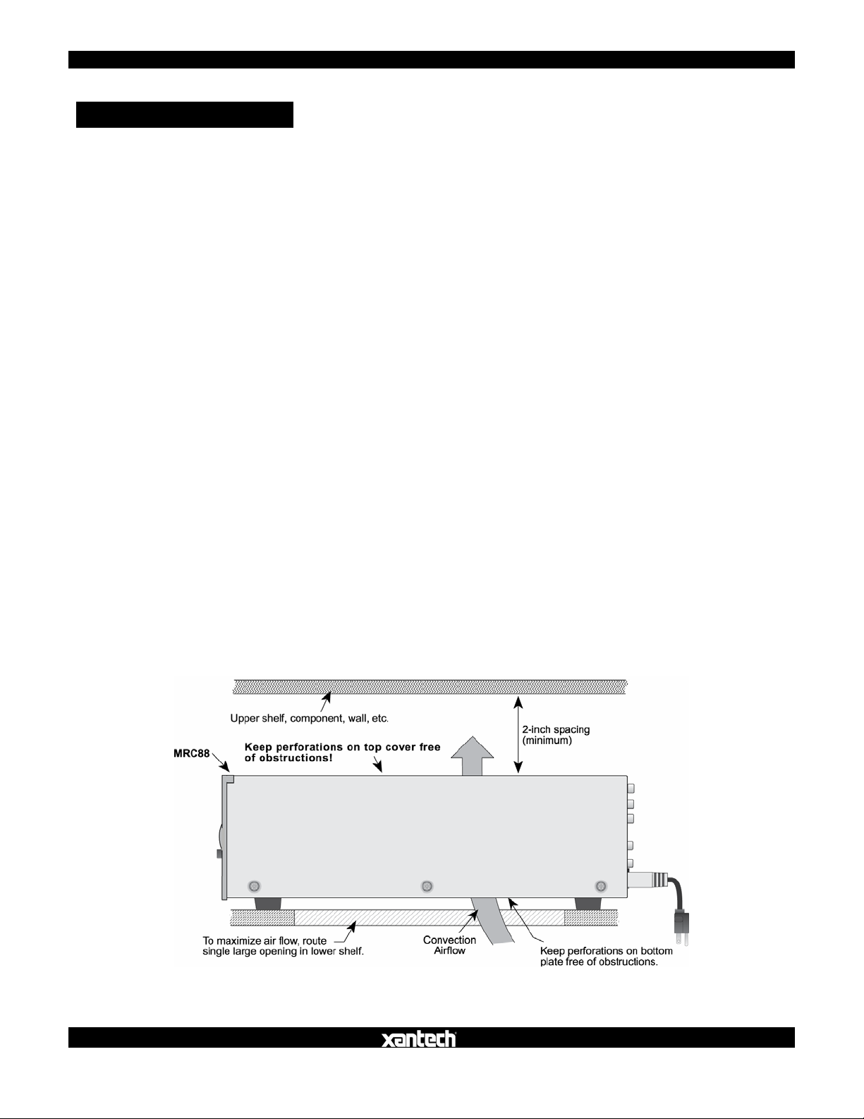
CONTROLLER LOCATION
Consider all of the flowing when planning the Controller location:
1. The MRC88 depends on the natural free flow of air up through the slot
perforations in the bottom plate, over the internal heat dissipating fins, then
out the top cover, for adequate cooling.
2. Provide large holes in the shelf below the MRC88 and allow at least 2 inches
of space above the top cover to allow adequate airflow.
3. Never remove the chassis feet. They are required to create space for
adequate airflow.
4. Pay close attention to the overall thermal conditions within a cabinet if other
heat generating components are also being used.
5. Both MRC88 and MRAUDIO8X8 have built-in fans that will automatically turn
on at a manufacturer specified temperature. Use of external fans, (quiet, boxer
type) is recommended to provide constant airflow for the MRC88 and other
heat generating components when appropriate.
6. When rack mounting, always use a single ventilated rack space panel above
and below the MRC88.
7. The MRC88 is designed for horizontal mounting on flat surfaces. When rack
mounting, use a proper rack shelf or drawer. (Middle Atlantic or equivalent.)
8. In multi-zone installations there will be large bundles of wire and cable to
accommodate audio, video, speaker and control connections. Be sure to leave
enough room for the leads and dress them in such a manner as to not block
airflow.
5
08905142A
Figure 2 – MRC88 Controller Installation
Page 6

MRC88 / MRAUDIO8X8 QUICK START GUIDE
MOUNTING THE KEYPAD
Keypad Location
• The MRC88 Keypad should be mounted in a convenient location, typically
near the entrance to a room where other room controls such as light switches
are located.
NOTE: Some light dimmers can interfere with the Keypad and IR Sensor. Test
compatibility prior to determining mounting location.
• Do not mount the Keypads in locations that will be exposed to sunlight or
bright artificial light. Bright light sources can interfere with the IR Sensor on the
Keypad, preventing use of remote controls. Cumulative light noise can
interfere with system and source control from other zones as well.
To mount the Keypad, use a plastic, dual-gang, new construction or retro fit Jbox and the included MRC88 Keypad Mounting Bracket as shown in Figure 3.
NOTE: Do not mount the Keypad in the same box with high voltage (AC)
devices. This can interfere with system performance and is a violation of
building/electrical code in most places.
6
08905142A
Figure 3 – Installing the MRC88 Keypad
Page 7
MRC88 / MRAUDIO8X8 QUICK START GUIDE
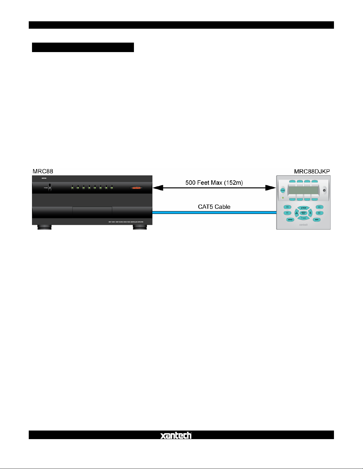
KEYPAD CABLE LENGTH
The maximum cable length for MRC88 connection to a single keypad is 500 feet
(152m) over CAT5 cable.
• Zone Keypad CAT5 cables should be pulled in home-runs from the keypad
locations to the MRC88 Controller.
• Label each end of the CAT5 with the Zone Number and Room Name to
assure proper connection and assist in troubleshooting.
• CAT5 cable must be properly terminated with RJ45 connectors for MRC88
Keypad connections. See Sections: Preparation, (Page 10) and Zone
Connections/ Keypads, (Page 14) in this Guide for additional information.
7
Figure 4 – MRC88 Keypad CAT5 Cable Length
NOTE: To connect additional MRC88 Keypads, WaterPads and IR Sensors,
see: MRC88/MRAUDIO8X8 Installation Instructions/Extended Runs and
Secondary Keypads in Zone, (Page 31). For connecting SPLCD Keypads
see: SmartPad LCD Installation & Programming Manual/MRC Controller
and Expansion Port Wiring, (Page 17).
08905142A
Page 8
MRC88 / MRAUDIO8X8 QUICK START GUIDE
8
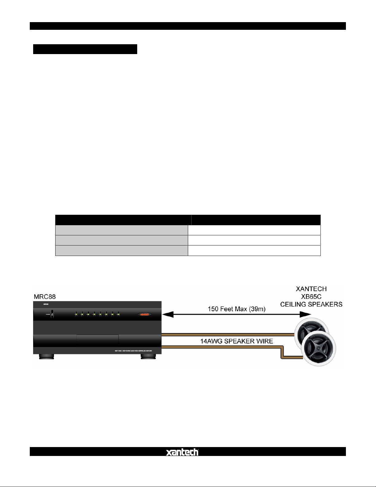
SPEAKER WIRE LENGTH
The maximum wire length for Zone Speaker connections is 150’ (39m) over
14AWG stranded wire.
• Speaker wire should be pulled in home-runs from the speaker locations to the
MRC88 Controller, two pair for each zone.
• Always use quality stranded speaker wire for zone speaker connections.
• Label each end of the speaker wire with the Zone Number and Room Name to
assure proper connection and assist in troubleshooting.
• MRC88 Speaker Terminals are 4-Ohm safe. Be sure the combined
impedance presented to the speaker terminals by the speakers (or any
combination of speakers) is greater than 4-Ohms.
Use the following Table to determine speaker wire gauge based upon the length
of the speaker wire run:
Length of Speaker Wire Run Gauge of Wire
30’ (9m) 18AWG
70’ (21m) 16AWG
150’ (39m) 14AWG
Table 1 – Speaker Wire Length/Gauge
08905142A
Figure 5 – MRC88 Zone Speaker Wire Length
Page 9
MRC88 / MRAUDIO8X8 QUICK START GUIDE
9
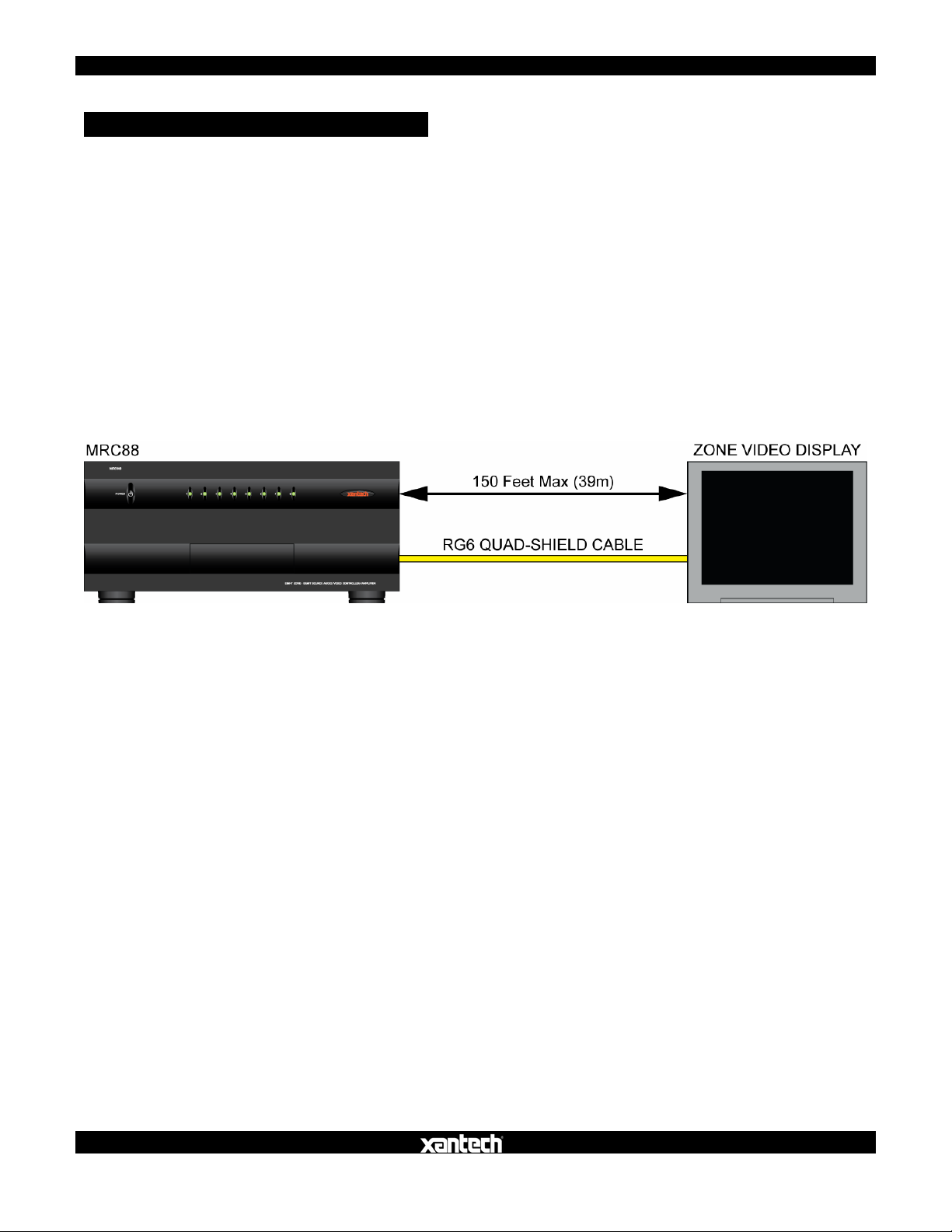
VIDEO DISPLAY CABLE LENGTH (MRC88)
The maximum coaxial cable length for Zone Video Output is 150’ over RG6
quad-shield cable.
• Coax for zone video should be pulled in home-runs from the zone video
display locations to the MRC88.
• Coax must be properly terminated with a shielded male RCA video plug on the
MRC88 end and as appropriate for connection to the video display. (Shielded
male RCA plug typical)
• Label each end of the coax with the Zone Number and Room Name to assure
proper connection and assist in troubleshooting.
Figure 6 – MRC88 Zone Video Cable Length
08905142A
Page 10

MRC88 / MRAUDIO8X8 QUICK START GUIDE
10
PREPARATION – WIRING
CAUTION: Power voltage for the keypad is transmitted along the CAT5 cable!
Incorrect wiring on this cable can destroy the MRC Keypad!
TERMINATING THE CAT5 CABLES
All MRC88 CAT5/RJ45 connections utilize the EIA/TIA 568B Standard pin-out as
shown in Figure 7.
Figure 7 – CAT5/RJ45 Pin-out (EIA/TIA 568B)
Cables should be configured in a pass through (pin to pin) configuration. To
terminate CAT5 cables:
1. Trim the end of the CAT5 so all eight conductors are the same length.
2. Using a CAT5 stripper, strip away approximately ½ inch of the cable jacket.
DO NOT STRIP THE INDIVIDUAL WIRES. Strip only enough of the jacket
to make connections. None of the individual wires should be hanging out
the end of the RJ45 connector when finished. There must be sufficient
jacket on the cable to allow the hinged tab on the RJ45 connector to apply
pressure to the cable jacket to function as a strain relief when pressed
together with the crimp tool.
3. With the RJ45 locking tab facing down, insert the individual wires into the
RJ45 connector per EIA/TIA 568B Standard pin-out as shown in Figure 7.
4. Use a RJ45 crimping tool to press the electrical contacts into the individual
wires and the hinged tab into place as the strain relief.
08905142A
Page 11

MRC88 / MRAUDIO8X8 QUICK START GUIDE
Test the cable connections using a proper CAT5 cable tester or use a
multimeter to check pin to pin continuity and for possible shorts. Using
either method, it is advisable to measure pins 3 and 6 to verify proper
voltage. A 12VDC measurement should be read when the positive probe is
on pin 6 and the negative probe is on pin 3. See Figure 7.
AC POWER
It is recommended, but not required, that the MRC88 Controller and head-end
source components be powered by a dedicated 20-amp circuit with an isolated
ground.
Whole-house system components turning on/off at various times (headend/common sources that may time out or local zone sources and amplifiers
turning on/off), lighting systems and other household appliances, can introduce
undesirable conditions (surges, ground hum, EMI, RFI, clicks and pops) on the
AC line that can adversely affect overall system performance.
An AC line conditioner can also be incorporated to protect components from
unstable AC and improve system performance by filtering AC line noise.
GROUNING SCREW
11
Connect to earth ground or other A/V components to aid in the
reduction of system noise such as an audible hum created by the
difference in ground potential between devices, if needed.
08905142A
Page 12
MRC88 / MRAUDIO8X8 QUICK START GUIDE
SOURCE CONNECTIONS
Be sure the MRC88 power is off and the unit is disconnected the from the AC
supply when making connections to avoid potential electrical shock and damage
to the MRC88, the Keypads, Sources and Speaker components.
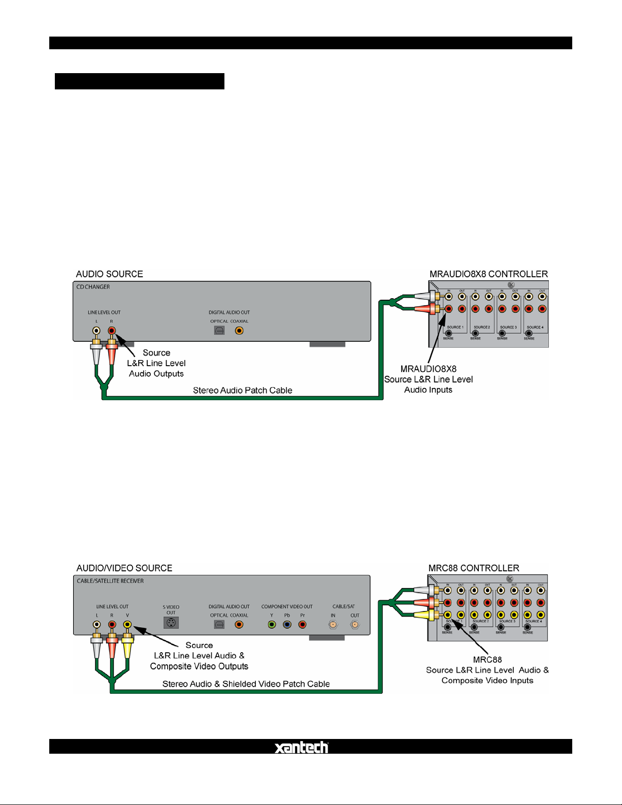
MRAUDIO8X8 (Audio Only)
1. Use a quality stereo audio patch cable to connect the L&R line level audio
outputs of a source component to the appropriate L&R line level source
audio inputs on the MRAUDIO8X8 rear panel.
2. Repeat for all sources.
12
Figure 8 – Audio Source Connections
MRC88 (Audio/Video)
1. Use quality stereo audio/video patch cables to connect the L&R line level
audio and composite video outputs of a source component to the
appropriate L&R line level source audio and composite video input on the
MRC88 rear panel.
2. Repeat for all sources.
Figure 9 – Audio/Video Source Connections
08905142A
Page 13
MRC88 / MRAUDIO8X8 QUICK START GUIDE
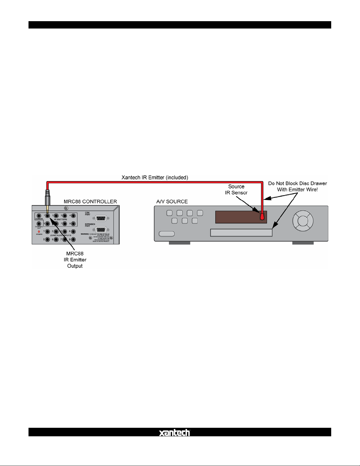
IR EMITTERS
Use the 8 included 283M Emitters for IR control of common source components.
1. Locate the IR sensor on the device to be controlled. If the sensor is not
obvious, shine a small flashlight into the device front panel display to locate
the sensor or refer to the product manual for that device.
2. Remove the adhesive protective cover on the flat side of the emitter and
attach the emitter over the IR sensor on the front panel of the source to be
controlled via IR.
3. Carefully pull the emitter wire around to the back of the unit. Do not block disc
and tape accesses. Do not pinch the wire between components.
4. Plug the emitter into the appropriate source IR Emitter Output on the MRC88
rear panel.
5. Repeat for all sources to be controlled via IR.
13
08905142A
Figure 10 – IR Emitter Connection
Page 14
MRC88 / MRAUDIO8X8 QUICK START GUIDE
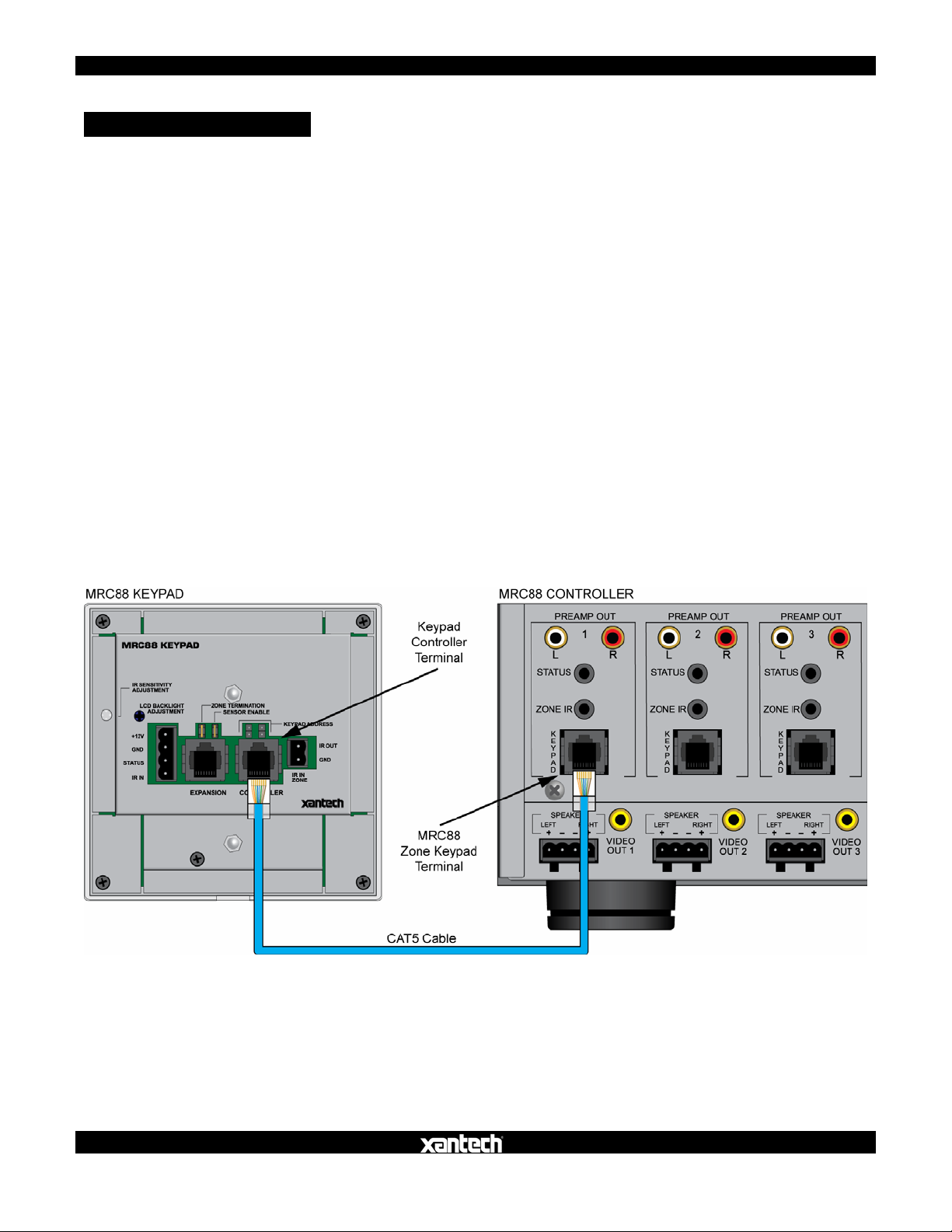
ZONE CONNECTIONS
KEYPADS
Prior to connecting the keypads, be sure the zone dual-gang boxes and keypad
mounting brackets have been installed and the keypad CAT5 runs have been
terminated and tested as described in the previous sections.
Head End Connections
1. Connect the zone CAT5 keypad cable to the appropriate Zone Keypad
Terminal on the MRC88 rear panel. Be sure the RJ45 connector ‘clicks’ into
place.
2. Repeat for all zones.
Zone Connections
1. Connect the zone CAT5 cable to the Controller Terminal on the MRC88
Keypad rear panel. Be sure the RJ45 connector ‘clicks’ into place.
2. Firmly snap the keypad into the Keypad Mounting Bracket. (Figure 3)
3. Repeat for all zones.
14
08905142A
Figure 11 – Zone Keypad Connections
Page 15

MRC88 / MRAUDIO8X8 QUICK START GUIDE
15
SPEAKERS
Head End Connections
Use the included 4-conductor plug-in connectors, (6 included) to connect speaker
wires to the MRC88.
1. Strip each speaker wire conductor’s insulation back about ¼ inch (6mm) and
twist the ends to prevent fraying.
2. Insert the leads into the appropriate “L+, L-”/“R+, R-” Terminals on each
plug-in connector. Confirm polarity. Slightly pull the connected wire to
confirm connection.
3. Be sure there are no loose strands that can cause shorts.
4. Plug the connector into the appropriate Zone Speaker Terminal.
5. Repeat for all zones.
Zone Connections
Prior to connecting speakers, be sure ceiling/wall openings have been properly
prepared and that any required mounting hardware is in place.
1. Strip each speaker wire conductor’s insulation back about ¼ inch (6mm) and
twist the ends to prevent fraying.
2. Connect the leads to the appropriate “L+, L-”/“R+, R-” Terminals on each
speaker. Confirm polarity. Slightly pull the connected wire to confirm
connection.
3. Be sure there are no loose strands that can cause shorts.
4. Install speakers per manufacturer’s instructions.
5. Repeat for all speakers in all zones.
08905142A
Figure 12 – Zone Speaker Connections
Page 16

MRC88 / MRAUDIO8X8 QUICK START GUIDE
16
VIDEO DISPLAY (MRC88)
Head End Connections
1. Connect the zone video cable to the appropriate Zone Video Output on the
MRC88 rear panel.
2. Repeat for all zones with video displays.
Zone Connections
Prior to connection, confirm the input to be used for the zone video feed and
appropriately terminate the video cable. (Shielded male RCA video plug typical.)
1. Connect the zone video cable to the appropriate composite video input on
the zone video display.
2. Use the other inputs on the zone video display for local devices such as DVD,
Sat, Cable, Video Games, etc. as needed.
3. Repeat for all zones with video displays.
08905142A
Figure 13 – Zone Video Display Connections
Page 17

MRC88 / MRAUDIO8X8 QUICK START GUIDE
17
SYSTEM INITIALIZATION
When all system connections (head-end and zones) have been made and
confirmed, connect the AC power cords for the MRC88 and all system devices.
Press the Power Button on the MRC88 Front Panel. The Xantech logo will
illuminate indicating the main power is ON. The Status LEDs (1-8) on the
MRC88 front panel will flash as follows while performing a system status check:
• Slow Orange Blink – Indicates general initialization is occurring.
• Fast Green Blink – Indicates that the keypad(s) on the associated zone is
currently being initialized.
• All Lights Off – Initialization is complete, system is ready for operation.
NOTE: If a fast green blink does not occur on any Status LED, confirm that the
keypad for the associated zone is connected at the MRC88 and at the keypad. If
the keypad is connected, test the CAT5 cable to confirm proper pin-out and
termination. See Section: Preparation – Wiring/Terminating The CAT5
Cables, (Page 10) in this Guide for additional information.
OUT-OF-BOX SYSTEM FUNCTIONALITY
A properly installed and connected MRC88 system has a default level of
functionality pre-programmed at the factory. It allows the system to be operated
on a most basic level for the purpose of testing overall system connections and
functionality (keypad, source, speaker, video display connections, etc).
In this default, the keypad buttons that control system operation (ON/OFF,
Volume, Source Select, Mute, etc) will be functional. The other buttons, (CH+,
CH-, Play, Stop, Pause, etc) will still need to be programmed using Xantech
Universal Dragon™ Software in order to be able to control the common sources.
08905142A
Page 18

MRC88 / MRAUDIO8X8 QUICK START GUIDE
18
The following Table shows out-of-box default functionality of a MRC88 Keypad
when connected to an un-programmed (factory default) MRC88:
Button Name
Power X
Source Buttons X
CH+ X
CH- X
Status X
Pause X
Select/Play X
REW X
FF X
Stop X
VOL+ X
VOL- X
Mute X
Default Function/
Non-Programmable
Default Function/
Programmable
No Default/
Must Be Programmed
Table 2 – MRC88 Keypad Default Functionality
SYSTEM DEFAULT SETTINGS
A MRC88 has a wide range of system, source and zone audio settings that can
be adjusted to tweak system performance based upon the source characteristics,
individual zone environment and user preference. Some of these adjustments
(Treble, Bass, Balance) can be made from the keypads and can be considered
user adjustable settings. The others, (Z-Adjust, Trim Levels and Code Group)
must be executed with a Xantech RC-68X IR Remote Programmer and should
be considered Installer Only adjustable settings.
The following Table shows the out-of-box default audio and Code Group Settings
of a MRC88:
Function Default Setting
Mute Off
Treble and Bass Flat
Balance Center
Z-Adjust Treble and Bass Flat
Z-Adjust Balance Center
Z-Adjust Max-V(olume) Cleared
Z-Adjust Max-On-V(olume) Cleared
Trim Levels Cleared
IR Code Group A8
Table 3 – MRC88 Default Audio and Code Group Settings
08905142A
Page 19

MRC88 / MRAUDIO8X8 QUICK START GUIDE
19
ZONE AUDIO ADJUSTMENTS (MRC88 Keypad – User Settings)
To adjust Treble, Bass and Balance from a MRC88 Keypad:
1. Simultaneously press the Status and VOL+ Buttons. The ‘Audio Setup
Mode’ will appear on the keypad LCD.
2. To adjust Balance, press the button under ‘BAL’. The ‘<’ REW Button will
shift audio to the left speaker. The ‘>’ FF Button will shift audio to the right
speaker. The Select/Play Button will restore center balance. Display will
return to normal after 10 seconds of no activity.
3. To adjust Treble or Bass, press the appropriate button in the LCD Display.
The ‘<’ Button will decrease the amount of treble or bass. The ‘>’ Button will
increase the treble or bass. The Select/Play Button will restore the audio to
the ‘flat’ setting. Display will return to normal after 10 seconds of no activity.
NOTE: These adjustments do not affect Z-ADJUST default settings.
AUDIO ADJUSTMENTS (Z-Adjust – Installer Settings)
These settings are ‘permanent’ settings that will affect system or zone
performance whenever the system is turned on, (even after a power outage) until
the settings are changed using the following procedure:
Trim
This procedure adjusts the MRC88 Source Input levels to compensate for the
different output levels of the common sources. When this procedure has been
properly executed, the audio level of the common sources should be the same
when switching from one source to another.
With all sources ON and playing relatively similar program material:
1. Cycle through the inputs to get a reference to the relative audio levels of the
different sources.
2. Using an RC68X with overlay “A”, select the input that has the lowest
apparent volume level (from any zone).
3. Point the RC68X at the IR sensor on the MRC88 Keypad
(IR sensor
enabled) and press the Trim Button (button F8). This activates the Trim
mode.
NOTE: Trim mode allows 10 seconds after each button press for the next
command to be executed. If 10 seconds is exceeded, simply press Trim
again. To confirm Trim mode, press the Mute ON Button. If the sound
mutes, the MRC88 Controller is NOT in the Trim mode.
4. Select any other input that sounds louder.
08905142A
Page 20

MRC88 / MRAUDIO8X8 QUICK START GUIDE
20
5. Adjust Volume Buttons until the apparent loudness is the same as the
device in Step 2 (lowest output).
6. Select another input that sounds louder.
7. Adjust Volume Buttons again until the apparent loudness is the same as
the device in Step 2 (lowest output).
8. Repeat this procedure for each remaining input.
9. Verify settings by selecting each input again, making adjustments as
necessary until all inputs have the same relative audio level.
10. When the last input is adjusted, press one more input (the same or any
other), to save the last setting.
11. Press the ADJ-OFF Button (Adjustments Off - 90) to drop out of the Trim
mode. (Trim mode will automatically drop out if you wait more than 10
seconds). The Trim settings are now saved for all inputs, for all zones,
completing this procedure.
Zone Audio Adjustments
These adjustments allow customized bass, treble, balance and maximum level
settings to best compliment the acoustics and preferences for each zone.
1. Go to the zone to be adjusted.
2. Using an RC68X, select desired Input (source).
3. Point the RC68X at the IR sensor on the MRC88 Keypad (IR sensor
enabled) and press the Z-ADJ Button (18). (This activates the Zone
Adjustments mode).
NOTE: Z-ADJ mode allows 10 seconds after each button press for the next
command to be executed. If 10 seconds is exceeded, simply press Z-ADJ
again. To confirm Z-ADJ mode, press the Mute On Button. If the sound
mutes, the MRC88 Controller is NOT in the Z-ADJ mode.
4. While listening to the program material, set Bass (E0, 88, & A8), Treble (20,
60, & 08) and Balance (C8, 58, D8) as desired. Repeat this procedure as
often as necessary to arrive at a pleasing tonal balance for the zone.
5. Adjust Volume Buttons (F0 & 98) to set the maximum volume desired for
the zone.
6. Press MAX-V Button (78) to save this maximum volume setting (this will
become the loudest volume possible in that zone).
7. Set the Volume level to the desired Zone On volume setting (i.e. the
maximum volume setting desired for when a zone is first turned ON – usually
a low to moderate listening level).
8. Press the ON-VOL Button (E1). This will now be the maximum volume to
which a zone will power on. The zone will turn on to the last volume set, up
to, but over the Zone On volume setting.
08905142A
Page 21

MRC88 / MRAUDIO8X8 QUICK START GUIDE
NOTE: The MRC88 remembers the last volume setting on a power down
and returns to that level when the Zone is powered back up. The ON-VOL
feature will ensure that if the volume was turned off at a loud volume setting,
when it is turned back on it will never go above the preset level (ON-VOL)
setting as a maximum. If user preference is to have the zone always turn on
the last volume set, do not program an ON-VOL Setting.
9. Press the ADJ-OFF Button to drop out of the Z-ADJ mode. (Z-ADJ mode
will drop out automatically after 10 seconds).The Z-ADJ settings are now
saved, completing the procedure.
10. Repeat Steps 1-9 for each zone.
RESTORE SYSTEM DEFAULT SETTINGS
To restore system default levels, press the recessed Reset Button behind the
MRC88 Front Panel Access Door twice within 1 second. System and Zone
settings will be reset to the settings shown in Table 3.
21
PROGRAMMING – UNIVERSAL DRAGON™
NOTE: This section only covers the most fundamental aspects of MRC88
programming: Installing the software, Firmware updates, Programming and
testing source IR commands, configuring the keypad source icons and
transferring the project. For complete MRC88 programming instructions, see:
MRC88/MRAUDIO8X8 Installation Instructions/Pre-Programming the
MRC88, (Page 34) and Programming the Controller, (Page 47).
SOFTWARE INSTALLATION
Universal Dragon™ minimum requirements:
• Windows 2000/XP/Vista
• 1.5GHz Processor or better
• 512MB Ram (1GB recommended)
• 600MB* Hard drive space (more recommended as projects expand)
• .NET Framework 2.0 (included)
• Mouse, USB, RS232 ports
*600MB = 300 MB Universal Dragon™, 300MB DotNet Framework
08905142A
Page 22

MRC88 / MRAUDIO8X8 QUICK START GUIDE
22
Universal Dragon™ can be installed using the included CD-ROM or as a
download from www.xantech.com
. Given the size of the program, it is
recommended that downloading only be done with a high-speed internet
connection. Universal Dragon™ will automatically update when a PC running
Universal Dragon™ is powered up, but it is always a good idea to check the
website for the latest version and Application Advisories before starting a new
project. To check for updates to Universal Dragon™, with the PC connected to
the internet, simply click Check For Updates in the Universal Dragon™ Help
Menu.
When finished installing Universal Dragon™ double click the shortcut on the PC
desktop to launch the program.
WHO AM I
Before starting a new project or doing any programming, it is highly
recommended that a ‘Who Am I’ procedure be performed to confirm the firmware
version of the MRC88. This will serve two purposes. One, it will confirm the
connection between the PC and the MRC88 that will be required for all
programming; and two, it will assure that the MRC is up to date with all of the
latest features and fixes.
Figure 14 – Who Am I/MRC Figure 15 – Firmware Page Link
1. Connect the included DB9 Programming Cable (Xantech P/N 05913410) to a
Serial Port on the PC and to the RS232 COM Port on the MRC88 Front Panel
or connect a USB Type-A to USB Type-B Cable (not included) to a USB Port
on the PC and to the USB COM Port on the MRC88 Front Panel.
2. In the Base Unit Menu, select WhoAmI, then MRC. The Who Am I?
Window will appear with all of the firmware version information for the MRC
and all connected keypads.
3. In the Favorites Menu, select Xantech Firmware Page. This will load the
Xantech Firmware Updates Page in the web browser.
4. Compare the firmware version from Who Am I? to the version on the
Firmware Updates Page. If the version on the Updates Page has a higher
08905142A
Page 23

MRC88 / MRAUDIO8X8 QUICK START GUIDE
version number, the firmware in the MRC88 should be updated using the
steps in the following section. If the firmware numbers are the same, click OK
in the Who Am I? Window and proceed to section: Starting A New MRC88 /
MRAUDIO8X8 Project, (Page 26).
FIRMWARE UPGRADE OPTIONS
The MRC88 has been designed to be “Future Proof”. As product feature
improvements are developed, new System Firmware versions will be made
available. Check www.xantech.com
for upgrades when starting a new MRC
Project.
There are two types of Firmware Upgrades. If a controller has a very old version
of firmware, more than 5 revs previous, or is just not functioning properly, that
calls for a Cold Upgrade. A controller with more recent firmware that is
functioning properly, should get a Warm Upgrade.
23
Figure 16 – www.xantech.com Firmware Updates Page
Downloading Firmware Files From The Web
1. Open the Universal Dragon™ MRC88 software. Make sure the PC is
connected to the Internet and that the MRC88 is connected to the computer’s
COM port (or USB port).
2. In the Favorites Menu, select Xantech Firmware Page. This will load the
Xantech Firmware Updates Page in the web browser. This step and the
following steps cannot be completed without an Internet connection.
3. The most recent MRC88 firmware update file will be featured in the
MRC88CTL / MRAUDIO8X8CTL Current Firmware Version Box. Click the
link to download the most current Firmware Update. For older versions click
08905142A
Page 24

MRC88 / MRAUDIO8X8 QUICK START GUIDE
24
on Archived Firmware Versions and scroll to the desired version (entries are
sorted with the newest entries at the top of the list and the oldest at the
bottom). Click on the desired filename link to begin the download process.
4. The File Download Window will appear. Select Save.
5. The Save As Window will open. Navigate to:
Program Files/Xantech/Universal Dragon/Firmware (usually located on the
local C Drive.). Click Save.
6. Once the download is complete, click on Close to close the download window.
The browser can also be closed if no longer needed.
WARM FIRMWARE UPGRADE
Warm Firmware Upgrades can be conducted to keep the MRC88 Controller up to
date and take advantage of new features.
Figure 17 – Warm Upgrade
1. Start Universal Dragon™, connect a programming cable to the front of the
MRC88 and open a MRC88 Project.
2. In the Base Unit Menu, select Upgrade, then MRC88, then Warm Upgrade.
3. The Open Window will appear. Double-click the firmware file that was just
downloaded in Step 6 above to begin the update process.
4. After the firmware transfer is completed, in the Base Unit Menu, select
WhoAmI. The WhoAmI ? Window will appear and display the three-digit
firmware version that was just loaded into the MRC88 Controller. If this is true,
the new firmware has been successfully installed and is ready for use. If not,
confirm downloaded firmware version, connections and try again.
5. After the upgrade is complete it recommended that a Transfer Project be
performed to assure that the system project has not been affected by the
firmware upgrade.
08905142A
Page 25

MRC88 / MRAUDIO8X8 QUICK START GUIDE
COLD FIRMWARE UPGRADE
Cold Firmware Upgrades should be performed when the MRC88 firmware is
more than 5 versions older than the most current version on the Xantech
Firmware Upgrade Page or if the MRC88 Controller is not functioning correctly.
Figure 18 – Cold Upgrade
1. Start Universal Dragon™, connect the programming cable to the front of the
MRC88 and open a MRC88 project.
2. In the Base Unit Menu, select Upgrade, then MRC88, then Cold Upgrade.
3. The Open Window will appear. Double-click the firmware file that was just
downloaded in Section: Downloading Firmware Files From the Web/Step 6
above to begin the update process.
4. Follow the instructions in the pop-up for completing the procedure.
5. After the firmware transfer is completed, in the Base Unit Menu, select
WhoAmI. The WhoAmI ? Window will appear and display the three-digit
firmware version that was just loaded into the MRC88 Controller. If this is true,
the new firmware has been successfully installed and is ready for use. If not,
confirm downloaded firmware version, connections and try again.
6. After the upgrade is complete it will be necessary to do a Transfer Project to
load the system project back into the Controller.
25
08905142A
Page 26

MRC88 / MRAUDIO8X8 QUICK START GUIDE
26
STARTING A NEW MRC88 / MRAUDIO8X8 PROJECT
For purpose of example, a Blank MRC88 Project similar to the system shown in
Figure 1 – Typical MRC88 System will be used.
Figure 19 – New Project Window
1. In the File Menu, select New Project. The New Project Window will appear.
2. Under Project Type, click the ‘+’ next to Audio/Video Distribution.
3. Select MRC88 (or MRAUDIO8X8 if appropriate).
4. Select the Radio Button for Blank Project. Click OK. A Blank MRC88 Project
will open.
5. Resize the MRC88 Window until the full keypad and all tabs are visible
(Figure 21).
08905142A
Page 27

MRC88 / MRAUDIO8X8 QUICK START GUIDE
CONFIGURING THE SOURCE ICONS
Each of the Source Icons can be configured to show the source on each input.
Each Icon can be up to four characters (CD, TUNR, DVD, MSRV, iPod, etc.)
Figure 20 – MRC Icon Text Window
1. Double click a Source Button or Icon to name the Source. The MRC Icon
Text Window will appear.
2. Type the Icon Name (CD, DVD, SAT, etc.) in the MRC Icon Text Window.
Click OK. The Icon will appear on the virtual keypad LCD.
3. Repeat for all Icons (sources).
PROGRAMMING SOURCE IR COMMANDS
IR Commands can be easily and quickly programmed to the keypad function
buttons (Play, Stop, Pause, etc.) using the built-in IR Code Library.
NOTE: Some buttons are not programmable and some have default factoryprogrammed functions already loaded. See section: Out-Of-Box Functionality
in this Guide for additional information (Page 17).
27
08905142A
Figure 21 – Programming IR Commands
Page 28

MRC88 / MRAUDIO8X8 QUICK START GUIDE
28
1. In the MRC88 Window select Zone 1 from the pull-down.
2. If the Palette Editor is not already open, in the View Menu, select Palette
Editor.
3. In the Palette Editor, click Show IR Library to open the IR Code Library.
4. Select the brand, (Denon, Pioneer, Sony, etc.) and the type of component,
(CD, DVD, Sat, etc.) connected to Input 1 on the MRC88 (Pioneer CD).
NOTE: Some brand/type sets (Pioneer CD, etc) will include multiple IR code
sets. It may be necessary to try the different code sets to find the proper set
for the device being used in the system. Typically, testing the Power or
discrete ON/OFF Commands is a good test.
Transport Devices (CD, DVD, VR, Music Server, MP3 Player, etc)
5. In the MRC88 Window, click the CD Source Select Button. It will highlight
dark blue.
6. If desired, click the play command in the IR Library to add the play
command to the CD source select macro. (By doing so, if stopped or
paused, the CD will automatically play any time CD is selected.) The
command will appear in the Command List Macro Window.
7. With the CD Source Button still highlighted, click the Play Button. Again,
click the play command in the IR Library to program the Play Button. This
creates a manual play command.
8. Repeat Step 7 for all CD commands. (Pause, REW, FF, Stop). REW and FF
can be programmed for track/chapter skip or scan per device type and user
preference. The CH+/- Buttons can be programmed for Disc Up/Down when
using a CD/DVD Changer.
Tuning Devices (AM/FM, Sat, Cable, XM, Sirius, etc.)
9. Click the SAT Source Select Button. Select the brand/type as described in
Step 4 above.
10. Program the CH+/- Buttons for channel, preset or scan UP/DOWN given
device type and user preference. Program the
UP/DOWN/LEFT/RIGHT/SELECT Buttons for cursor functions when
appropriate for menu driven devices, or other functions per device type and
user preference.
11. Repeat Steps 4-9 for all Sources.
NOTE: Commands not found in the IR Code Library can be learned or
imported in Universal Dragon™. See: MRC88/MRAUDIO8X8 Installation
Instructions/Learning IR Commands, (Page 39) for additional information.
08905142A
Page 29

MRC88 / MRAUDIO8X8 QUICK START GUIDE
29
TEST IR COMMANDS
To test IR Commands, the PC must be connected to either the RS232 COM or
USB COM Port on the MRC88 Front Panel and IR emitters must be connected to
the appropriate IR Emitter Outputs on the MRC88 Rear Panel and correctly
attached to the appropriate devices.
Figure 22 – Select Test Mode
1. In the Universal Dragon™ Tool Bar, in the Mode Menu, select Test.
2. On the virtual keypad, click the Power Button. The MRC88 Front Panel
Zone 1 LED and Zone 1 Keypad should turn ON.
3. Click the CD Button. The Keypad should switch to Source 1 (CD). If a play
command was added to the source select macro, the device should play.
4. Click all other buttons that have been programmed with IR Commands for the
selected source. Visually confirm function on the device.
5. Repeat Steps 3-4 for all sources.
6. Click the Power Button. The MRC88 Front Panel Zone 1 LED and Zone 1
Keypad should turn OFF.
7. In the Universal Dragon™ Tool Bar, in the Mode Menu, select Normal.
8. Reprogram any commands that did not function properly or that were missed
in initial programming.
08905142A
Page 30

MRC88 / MRAUDIO8X8 QUICK START GUIDE
30
PUNCH SYSTEM (Copy IR Programming to all Zones)
Once the IR programming for Zone 1 has been confirmed, if all zones are to have
the same programming, the Zone 1 Keypad can be ‘punched’ or copied to all
zones saving valuable programming time.
Figure 23 – Punch System
1. With Zone 1 (the programmed zone) selected in the MRC88 Window, right
click any button.
2. Select Punch (System). A Punch System Level Caution Message will
appear. Click YES. All programming for Zone 1 will now be punched to all
zones.
3. Test all zones to confirm programming as described in Section: Test IR
Commands, (Page 29) in this Guide.
08905142A
Page 31

MRC88 / MRAUDIO8X8 QUICK START GUIDE
TRANSFER THE PROJECT
With all Zone IR programming confirmed, the Project can be transferred to the
MRC88. With the PC connected to either the RS232 COM or USB COM Port on
the MRC88 Front Panel:
Figure 24 – Transfer Data Window
1. In the File Menu, select Transfer Project or in the Tool Bar, click the
Transfer Project Icon.
2. The Transfer Data Window will appear. When transfer is complete, the
message: Transfer Succeeded will display in the window. Click OK.
3. The MRC88 will update itself and the keypads.
4. The System is now ready for use.
5. If the message: ‘Error while Transmitting Data…’ displays in the Transfer
Window, check connection between PC and MRC88. Confirm Com Port. See:
MRC88/MRAUDIO8X8 Installation Instructions/Troubleshooting, (Page
92) for additional information.
31
08905142A
Page 32

MRC88 / MRAUDIO8X8 QUICK START GUIDE
32
SAVING THE PROJECT
Unlike previous versions of Xantech Dragon Drop-IR™ Software, Universal
Dragon™ does not auto-save work in progress. Therefore it is necessary to save
all work and it is highly recommended that it be saved frequently.
Figure 25 – Save Project
1. In the File Menu, select Save Project or in the Tool Bar, click the Save
Project Icon.
2. The Save As Window will appear for a new, unsaved project. (No window will
appear when saving new work on a previously saved project.)
3. The default Folder for Universal Dragon™ Projects is:
C:\Program Files\Xantech\Universal Dragon vX.X\Projects. Navigate to
this location if the Projects Folder does not appear in the Save In Box.
4. Enter a name for the project in the File Name Box. (The client’s name, ie:
‘Jones Home’ is a good way to keep track of individual projects.)
5. Click Save.
6. To close a project without saving changes, In the File Menu, select Close
Project. In the Save Window, click NO. The project will close without saving
changes. The project will still be available for future use, in its last saved form.
08905142A
Page 33

MRC88 / MRAUDIO8X8 QUICK START GUIDE
SAVE PROJECT AS
When programming a project for a new client that is similar or identical to an
existing project, Open the existing project. In the File Menu select Save As,
then enter the new file name as described in Step 4 above. The project will be
saved with the new file name. At this point, the project can be transferred to
the Controller if no additional changes are required, or after making the
necessary changes for the new client.
PROJECT RECOVERY
1. In the File Menu, select Base Unit -> Project Recovery -> MRC88.
2. Universal Dragon will extract the project from the MRC88.
3. If the message: ‘Error recovering project.’ displays in the Project
Recovery Window, check connection between PC and MRC88. Confirm
Com Port. See: MRC88/MRAUDIO8X8 Installation
Instructions/Troubleshooting, (Page 92) for additional information.
33
Figure 26 – Project Recovery
ADVANCED PROGRAMMING
For complete advanced feature programming instructions, see:
MRC88/MRAUDIO8X8 Installation Instructions/Pre-Programming the
MRC88, (Page 34) and Programming the Controller, (Page 47).
08905142A
Page 34

MRC88 / MRAUDIO8X8 QUICK START GUIDE
APPENDIX
MRC88 / MRAUDIO8X8 CONTROLLER/AMPLIFIER PANEL FEATURE DESCRIPTIONS
34
Figure 26 – MRC88 Front Panel Features
MRC88 FRONT PANEL FEATURES AND CONNECTIONS
1. Front Panel.
2. Chassis Feet. Set high enough to provide through-chassis cooling by natural convection.
3. Master AC Line On/Off Switch. Turns AC power On/Off to the entire unit.
4. Power and Status LED Indicators. Eight indicators, one for each Zone, provide the following status
information:
System Status (Power-Up Mode)
a) Slow Orange Blink – indi cates general initialization is occurring.
b) Fast Green Blink – indicates that a keypad on the associated zone is currently being initialized.
c) All Lights Off – initialization is done, system is ready for operation.
Zone Status (Active-Operational Mode)
a) Steady Green – indicates that the Zone is Active (Keypad ON), is not muted and is not within 5 dB of
MAX-V.
b) Steady Red – indicates that the Zone is Active, is not muted and is within 5 dB of MAX-V.
08905142A
Page 35

MRC88 / MRAUDIO8X8 QUICK START GUIDE
35
c) Slow Green Blink – indicates that the Zone is in the Active, is muted and is not within 5 dB of MAX-V.
d) Slow Red Blink – indicates that the Zone is Active, is muted and is within 5 dB of MAX-V.
e) Fast Green Blink – indicates that Zone is Active, is being ramped Up or Down and is not within 5 dB of
MAX-V.
f) Fast Red Blink – indicates that the Zone is Active, is being ramped Up or Down and is within 5 dB of
MAX-V.
g) Off to indicate that Zone is in Not Active (Keypad OFF).
5. Front Panel Access Door. Push gently on lower half of door to open. Allows access to programming
connections, Level Reset and Front Panel Source 8 A/V Input.
6. Level Reset. Pressing this button twice within 1 second restores all of the Factory Default Settings for all
zones. The Factory Defaults are as follows:
• Mute Off
• Treble and Bass Flat
• Balance Centered
• Z-Adjust Treble and Bass Flat
• Z-Adjust Balance Centered
• Z-Adjust Max-V Cleared
• Z-Adjust Max-On-V Cleared
• Trim Levels Cleared
NOTE: The Control Amp will always return to last set values (plus any unaltered factory defaults) after main
power shut down or after any power interruptions.
7. IR Learning Eye. The IR Eye on the MRC88 Controller front panel allows teaching IR Codes to Universal
Dragon™ Software via the Control Amp when connected to a PC‘s com port.
8. RS232 Com Port. DB9 Connector. Used to program the MRC88 Controller from a PC using Universal
Dragon™ Software and for Firmware Upgrades.
9. PROTECT On/Off Switch. Selects between Programming Mode (OFF position) and PROTECT (ON) position
to keep program secure in memory. It is recommended to leave this switch in the ON position at all times.
10. STATUS A Led. Green Activity LED, lights during Program Download from Universal Dragon™ Software,
during IR Learning and for Firmware Upgrades when using the RS232 Port located on the front panel.
11. USB Com Port. Used to program the MRC88 Controller from a PC using Universal Dragon™ Software and
for Firmware Upgrades.
12. STATUS B Led. Green Activity LED, lights during Program Download from Universal Dragon™ Software,
during IR Learning and for Firmware Upgrades when using the USB Port located on the front panel.
13. Source 8 AUDIO IN L/R. Front panel Source 8 line level audio input. Gold-plated RCA Jacks for use with any
desired A/V source component such as Camcorder, Video Game or other device.
14. Source 8 VIDEO IN. (MRC88 Only) Front panel Source 8 composite video input. Gold-plated RCA Jacks for
use with any desired A/V source component such as Camcorder, Video Game or other device.
15. Source 8 Front/Rear Selector Switch. Selects whether the Source 8 Audio/Video inputs will come from the
Front (F) or Rear (R) panel jacks.
08905142A
Page 36

MRC88 / MRAUDIO8X8 QUICK START GUIDE
36
Figure 27 – MRC88 Rear Panel Features
MRC88 REAR PANEL FEATURES AND CONNECTIONS
16. Keypad Terminals (8). Each Zone has one RJ-45 jack for Keypad Interface. Each connector interfaces the
following: Power (Enough for 1 Primary & up to 1 Secondary Keypad per Zone), RS-485 Data I/O, and IR
Input.
17. Speaker Terminals (6). Plug-in 4-terminal screw type connectors for zones 1 thru 6, permit speaker wire
sizes up to 12AWG.
18. Composite Video Output (8). RCA type connector sends zone selected source video to the composite video
input on a zone TV or modulator.
19. Status Out (8). Provides a control output of +12 VDC that turns on and off with the zone to drive voltage
sensing relay modules and AC strips.
20. Control Out (8). Mono 3.5mm Mini Phone Jack provides a Control Output that goes high (+12 volts) when
any Zone is first turned ON and goes low (0 volts) when the last Zone is turned OFF. [Tip=+VDC;
Shield=GND]
21. Remote Amp Control Out (CO1 & CO2). Stereo 3.5mm Mini Phone Jack connects to CONTROL IN jack of
Remote Amp PA435X or PA4100X. Provides STANDBY and MUTE Control of remote Amp from Zone 7
(CO1) and Zone 8 (CO2). [Tip = STANDBY Logic; Ring = MUTE Logic; Shield = GND]
22. Source Component Input Connections (8)
a) Source Audio Inputs. Gold-plated RCA Jacks for Stereo/Dolby Pro line level audio input from source
components.
b) Source Video Inputs. Gold-plated RCA Jacks for composite video input from source components.
c) Sense Inputs. 3.5mm Stereo Mini Phone Jacks for use with any Xantech SM Series Sensor Module.
23. Source Loop-Thru Connections (8).
a) Audio Loop-Thru. Parallel Connection to Audio Inputs for connecting Audio Source to another MRC-88
in Expanded Mode or to other local devices. This is not an active output.
08905142A
Page 37

MRC88 / MRAUDIO8X8 QUICK START GUIDE
37
b) Video Loop-Thru. Buffered Video Connection for connecting Input Video Source to another MRC-88 in
Expanded Mode or to other local devices. NOTE: Since this is a Buffered video connection, this loopthru
is not active when POWER is removed from the MRC88
24. Zone Audio Inputs (8). 3.5mm Stereo Mini Phone Jack for Zone specific stereo audio Server Inputs. Zone
Audio Inputs override rear panel, Source 1 connection. Allows each of the 8 Zones to have a dedicated
Server Output by selecting Source 1 on keypad. Can also be used with Xantech ZA Series Zone Audio
components for adding zone local source audio devices that can be selected by a keypad/re mote and played
through the MRC88 to that zone.
25. Zone Audio Pre-Amp Out (8). Gold-plated RCA Jacks for connecting Zone Audio Output to an external
amplifier. For use with applications where either more power is required for Zone or passing to a Dolby Pro
compatible receiver for theater quality audio in zone.
26. IR Emitters (1-8). 3.5mm Mono Mini Phone Jacks. These mini jacks are for the connection of IR emitters to
individually control the eight common source components. These jacks are “steerable” with Universal
Dragon™ Software for IR Routing and Priority Lockout. IR received from a Zone will be routed to the emitter
port corresponding to the Zones active source selection. Can also be configured as 8 common emitter ports
with Universal Dragon™ Software.
27. IR Emitter (Common). 3.5mm Mono Mini Phone Jacks. Single Common IR Output that can be used to
control devices such as Multi Zone Audio Server, motorized drapery systems, TV lifts and lighting systems or
any other IR controlled component. IR Received from any Zones Keypad will be output the Common emitter
port regardless of source selection.
28. Zone IR Out (8). 3.5mm Mono Mini Phone Jacks. IR received from a Zone will always be passed to the
corresponding Zone IR output. This can be used to control Zone Specific components not located in the zone.
29. Com Port. DB9 RS232 Control Port allows full control from an external PC component of all Internal Amplifier
Commands of the MRC88 Controller and the ability to trigger programmed IR Macros for control of devices
connected to the Controllers emitter ports. The Com Port can also be used in the reverse to send ASCII/Hex
commands OUT to control an external RS232 device directly from the MRC88 Keypad and/or handheld
remote.
30. Expansion Port. DB15. Allows two MRC88’s to be connected together, via included Expansion Cable, to
provide an 8 Source/16 Zone system with full control between units. With optional cable (Xantech P/N
05913565) can also be used as an additional RS232 serial control port.
31. User Replaceable Fuse. 10 AMP 250 VAC, Slow Blow Fuse (Domestic version). 5 AMP 250 VAC, Time-Lag
Fuse (European version).
32. AC Power Input. Standard IEC 3-Conductor AC Line Cord Receptacle for plug-in of a 3-conductor power line
cord.
33. Grounding Screw. “Knurled Screw” provides a means for chassis connection to earth ground or to other
Audio/Video products to aid in the reduction of system noise.
34. Power On/Off LED. This LED indicates the Main Power ON/OFF Condition of the MRC88 Controller.
08905142A
Page 38

MRC88 / MRAUDIO8X8 QUICK START GUIDE
MRC88 KEYPAD FEATURE DESCRIPTIONS
38
Figure 28 – MRC88 Keypad Front Panel Features
MRC88 KEYPAD FRONT PANEL FEATURES
1. MRC88 Keypad.
2. Power. Turns the zone ON and OFF. Can be programmed with IR codes or sequences.
3. IR Sensor. Receives IR from hand-held remotes to control both source components and the MRC88 system.
A Pre-Programmed remote such as the Xantech MRCREMRP or a Programma ble Learning Remote such as
the Xantech URC2 is recommended for integrating the IR commands of the MRC88 and source components
into a single controller. The IR sensor is compatible with most brands of remote controls, though some
remotes may not be programmable and will therefore only control the source components.
4. Status Indicator LED. Will indicate zone/system status and will flash as IR is received at the IR Sensor.
These indicators, one for each Keypad, provide the following Information:
a) LED Off = Zone OFF
b) Steady Green = Zone ON
c) Slow Green Blink = Zone MUTE
d) Fast Red Blink = IR Sensor INPUT or Keypad OUTPUT
e) Fast Amber Blink = System BUSY
5. LCD Display. When the zone power is ON, the LCD will indicate the selected source, zone volume level,
zone and system status and other system conditions. The display is automatically backlit when any button is
pressed (backlight is configurable via Universal Dragon™ software).
6. Source 1-4 Selector Buttons. Pressing of Source Button selects the corresponding source’s Audio/Video
signal to be played in the Zone of the keypad pressed. Pressing of the Source Button will reverse the source
08905142A
Page 39

MRC88 / MRAUDIO8X8 QUICK START GUIDE
icon on the LCD Display and sends IR commands programmed to the button (if any) to the corresponding
source and common emitter outputs as well as Zone Emitter port.
7. Source 5-8 Selector Buttons. Pressing of Source Button selects the corresponding source’s Audio/Video
signal to be played in the Zone of the keypad pressed. Pressing of the Source Button will reverse the source
icon on the LCD Display and sends IR commands programmed to the button (if any) to the corresponding
source and common emitter outputs as well as Zone Emitter port.
8. Vol
9. Vol
10. Mute. Mutes zone speaker output. Sends IR commands programmed to this button (if any) to the selected
11. CH
12. CH
13. Status. Displays zone and system status. Allows access to Dynamic Zone Linking and Zone EQ/Balance
14. Select/Play, Stop, Pause, Rew, FF. Each send IR commands programmed to these buttons to the selected
+. Increases zone volume and moves the Volume Bar on the LCD Display to indicate volume level (non-
programmable).
-. Decreases zone volume and moves the Volume Bar on the LCD Display to indicate volume level (non-
programmable).
source emitter, common emitter, and zone emitter outputs.
+. Sends IR commands programmed to this button to the selected source emitter, common emitter, and
zone emitter outputs.
-. Sends IR commands programmed to this button to the selected source emitter, common emitter, and
zone emitter outputs.
settings (non-programmable).
source emitter, common emitter, and zone emitter outputs.
39
08905142A
Page 40

MRC88 / MRAUDIO8X8 QUICK START GUIDE
40
Figure 29 – MRC88 Keypad Rear Panel Features
MRC88 KEYPAD - REAR PANEL FEATURES AND CONNECTIONS
15. Controller Terminal. RJ45 Jack. Connects Keypad to zone keypad input on MRC88 Controller via CAT5
cable.
16. Expansion Terminal. RJ45 Jack. Allows keypad to be daisy chained to another keypad for multiple control
locations within a zone. Up to 4 keypads are supported per zone.
17. Keypad Address. Pair of Jumpers. Used to assign Keypad Address. Each Keypad in a zone must have a
unique address (up to 4 keypads in a Zone).
18. Zone Termination. Jumper. Do not remove jumper if there is only one keypad in a zone. If there is more then
one keypad in a zone, remove from all but the last keypad in the daisy chain configuration.
19. Sensor Enable. Jumper. Enables IR sensor on Keypad. Remove when using an external IR receiver.
20. IR Sensitivity Adjustment. Carefully adjust for background light level to prevent false triggering of the IR
circuits. Slowly turn counter-clockwise to reduce sensitivity.
21. LCD Backlight Adjustment. Adjusts brightness of LCD backlight. This adjustment does not affect the
backlight level for the buttons. Slowly turn counter-clockwise to reduce brightness.
22. IR In-Zone. 2-Terminal WECO style socket - Zone IR out for local ‘In-Zone’ emitter out. Used for IR control of
equipment in the same location as the keypad. Any IR generated from within the Zone (or routed to that zone
from another) will be output from the IR IN-Zone connector as well as the Zone IR jack on the rear of the
Controller. This feature is ‘selectable’ via Universal Dragon™ Software.
08905142A
Page 41

MRC88 / MRAUDIO8X8 QUICK START GUIDE
41
23. External IR Terminal Block. 4-Terminal WECO style socket – Allows connection of other Xantech IR
Receivers and/or Keypads to be used in conjunction with the MRC88. (i.e. Use WaterPad Keypad in subzone
in shower or outdoor zone or Plasma Friendly IR Receiver in place of Keypad IR Receiver).
24. Snap-in Pins. These pins snap into the MRC88 Keypad wall bracket for mounting.
SPECIFICATIONS
Audio (ea channel)
Min Input..............................................................................................................250mV for full rated Output
Input Overload........................................................................................................>2.2 V RMS (@ max VC)
Input Impedance.........................................................................................................................> 20 k Ohms
Power Output..................................................................................................... 35 Watts RMS @ 4-8 Ohms
Signal to Noise..................................................................................................................>96dB A-Weighted
THD (VC -10dB) ......................................................................................................<0.08% @ 2V input level
Frequency Response (± 3dB)............................................................................................... 12 Hz to 55 kHz
Bass Control Range (@ 100Hz)..................................................................................± 14dB (in 2 dB steps)
Treble Control Range (@ 10 kHz)...............................................................................± 14dB (in 2 dB steps)
Video
Input/Output Impedance...................................................................................................................75 Ohms
Video Insertion Loss....................................................................................................0 dB (50 Hz to 6 MHz)
IR Sensor
IR Modulation Frequency Bandwidth ................................................................................. 30 Hz to 100 kHz
Nominal Reception Range................................................................................................................. >30 feet
Nominal Reception Angle.................................................................................................40 degrees off axis
General
RC68 Code Group Number........................................................................................................................ A8
Control Output .......................................................................................................................... 12v @ 50 mA
Status Output.............................................................................................................................12v @ 50 mA
Power Requirements..................................................................................120 VAC, 60 Hz, 660 Watts max,
TMRA 30° Celsius - If this temperature is exceeded, you will need
to provide additional ventilation to insure proper operation.
Gold Plated RCA type phono jacks.............................................................................. All A/V inputs/outputs
Dimensions (Controller)............................................17” W x 7.5 H x 11.75 D (432mm x 191 mm x 298mm)
Dimensions (Keypad)....................................................4.5” W x 4.5 H x 1.5 D (114mm x 114 mm x 38mm)
Weight (Controller) ..........................................................................................................
Weight (Keypad)......................................................................................................................0.6 lbs (0.3 kg)
CERTIFICATIONS
Product is certified as marked on the rear panel.
.......45 lbs (20.4 kg)
08905142A
Page 42

NOTES
Page 43

NOTES
Page 44

MRC88 / MRAUDIO8X8 QUICK START GUIDE
Xantech Corporation
13100 Telfair Avenue, 2/F
Sylmar, CA 91342
Quick Start Guide, MRC88, MRAUDIO8X8
© 2007 Xantech Corporation, Document #08905142A
This document is copyright protected. No part of this manual may be copied or reproduced in any form without
prior written consent from Xantech Corporation.
Xantech Corporation shall not be liable for operational, technical, or editorial errors/omi ssions made in this
document.
44
08905142A
 Loading...