

Page 1
INSTALLATION INSTRUCTIONS
MIRV1
IR/MOTORIZED VOLUME CONTROLLER
The MIRV1 is an IR or manually operated volume controller that works in conjunction with the RAT1 Remote
Autotransformer or the RGC11 Remote Gain Control Modules. Together, they allow speaker or line level
volume control in any room, using a standard 3 or 4-conductor Xantech IR bus system. You can also use
two or more MIRV1's in the same room or listening area, for convenient manual operation, or in conjunction
with a Xantech IR receiver for both remote and manual volume operations. Knob mounted indicator allows
visual verification of volume rotation and position and also serves as a system power ON/OFF (status)
indicator.
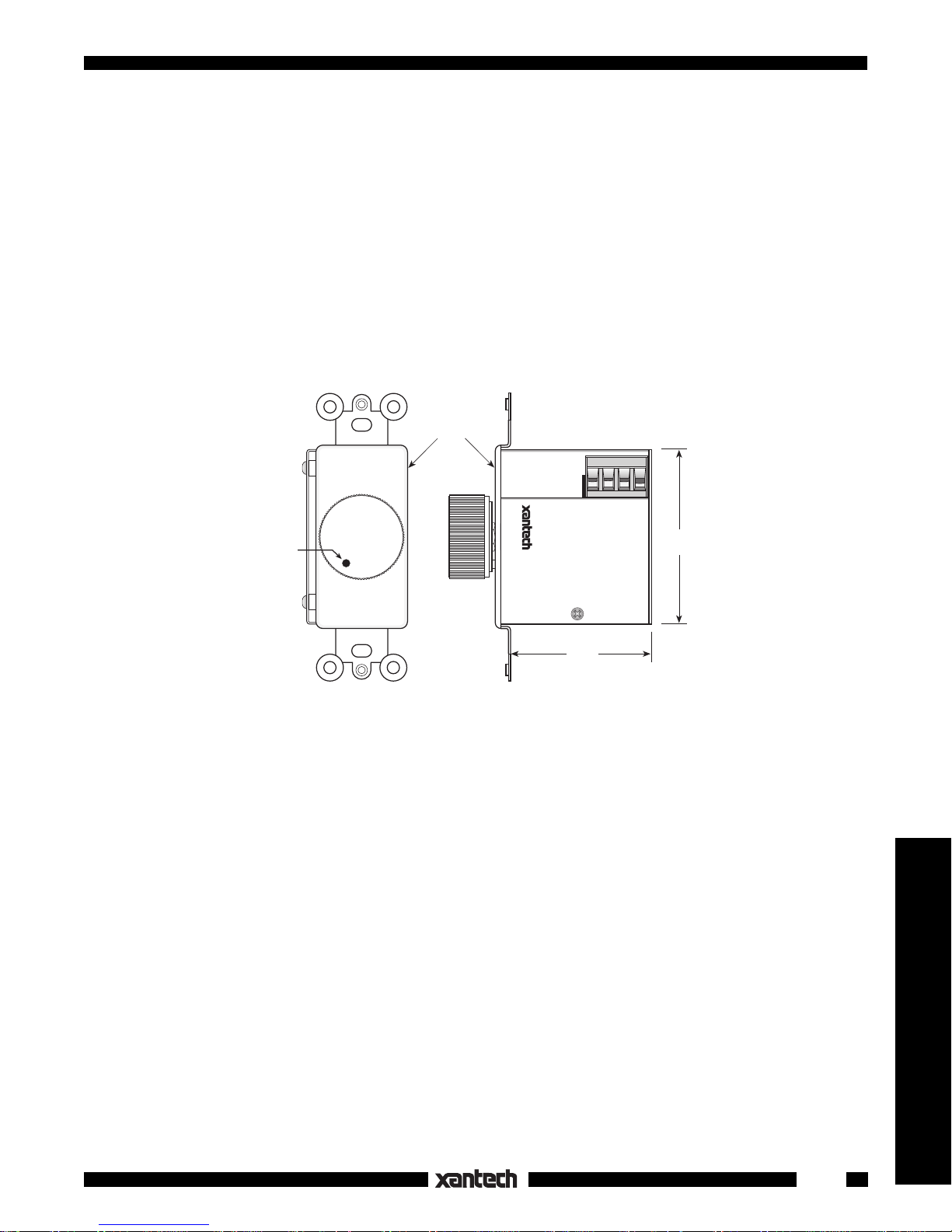
Insert
Plate
+12VDC
GROUND
STATUS
MOTORIZED VOLUME
CONTROLLER
SYLMAR, CA
MIRV1
IR IN
2-1/2
(64mm)
Fig. 1 The MIRV1
LED
Status
Indicator
2-1/16
(53mm)
FEATURES AND SPECIFICATIONS
• Servo action causes multiple MIRV1's to automatically track each other's position and simultaneously
drive the RAT1 or RGC11 volume settings.
• LED in knob blinks with knob rotation and also serves as a system ON/OFF status indicator.
• Requires IR commands from the RC68+ (or RC68) Programmer, or manual rotation, for volume
operations.
2
• Using the RC68+ Programmer, internal E
PROM can be set to different group codes for independent
operation of MIRV1's in a common IR bus system.
• Factory preset Group Code number is 30.
• Plug-in 4-terminal screw-type connector for IR, STATUS and +12V.
• Recommended wire for 4-conductor bus: 24 gauge solid or stranded wire up to 150', 22 gauge up to 400',
20 gauge up to 1500' and 18 gauge up to 4000' (unshielded OK).
• Power: 12V DC @ 60 mA. Powered directly or from a RAT1.
• Use decorator-style wall cover plate.
• One nut disassembly allows custom painting of Insert Plate.
• Knob and plate are pre-finished in either white (MIRV1-W) or ivory (MIRV1-I).
• Fits standard single gang J-box.
• Depth behind plate: 2-1/8 inches.
Speakers & Volume Controls
1
Page 2
RC68+ PROGRAMMER / REMOTE CONTROL
The RC68+ (or RC68) programmer (available separately) contains all the commands necessary to operate
the MIRV1.
• You will need it to program universal learning devices such as the Xantech URC-1 learning remote, the
Xantech Smart Pads, the 590 Programmable Controller, the 710 Fone Link, etc., with commands that
operate the MIRV1, RAT1 and the RGC11.
• NOTE: The RC68+ codes operate several other Xantech models as well, such as the RS41AV, RP41AV,
only
ZPR68, etc. Therefore,
the button descriptions that apply to the operation of the MIRV1 with the
RAT1 are listed below. All others should be ignored.
CAUTION: While the RC68+ can be used as a handheld remote control, it is highly recommended it not
be given to the final user for the following reasons:
• Since it includes selectable code groups, the user may inadvertently alter the installer configurations.
• Also, since the user will require IR commands from other brands of equipment to control the total system,
in addition to those of the MIRV1, all commands should be consolidated into one learning device, for ease
of use.
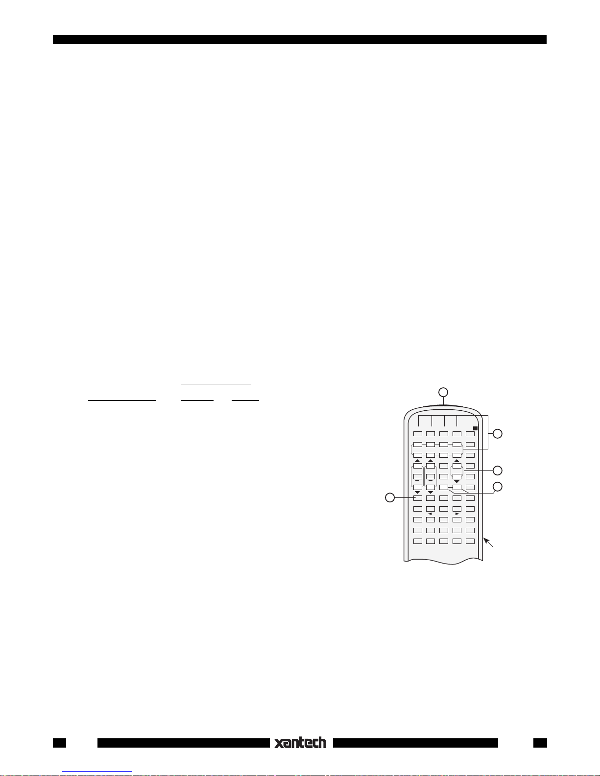
APPLICABLE RC68+ BUTTON DESCRIPTIONS
1. IR Emitter Lens
2. Instant Volume Presets. These buttons allow direct preset activation of any of the 10 volume steps
on the RAT1. This is useful for "audio scene" ambiance settings for rooms or an instant partial mute
action.
The relationship of the RC68+ buttons to the MIRV1 and RAT1 volume step positions is as follows:
Volume Step #
RC68+ Button MIRV1 RAT1
1
A 1 (Off, Min Vol)
MUTE
A
2
VOL
3
4
RC68+
B 2 1 (Off, Min Vol)
C 3 1 (Off, Min Vol)
ADJ-OFF 4 2
153
264
375
486
597
5
A B C ADJ-OFF
80 48 10 90 01
1234
00 C0 50 D0 41
INPUT
5678
40 A0 30 B0 21
GLOBAL
20 E0 70 F0 61
TREBLE
BASS
Z-ADJ
60 88 18 98 09
08 A8 38 B8 29
ON OFF
28 E8 78 F8 69
E-FLAT LAST MAX-V TRIM
68 C8 58 D8 49
OFF C-BAL
E1 89 C9 A9 E9
71 19 59 39 79
F1 99 D9 B9 F9
6108
7119
8 12 10 (Max Vol)
Fig. 2 The RC68 Programmer
3. VOLUME Up/Down buttons. Each individual press will cause the RAT1 to increase or decrease
volume level by one step, over a total of 10 steps. Each step causes a change of 3 to 6 dB/step and
a maximum attenuation of 35 dB to the lowest active step (#2). The lowest step (#1) switches the signal
off.
When buttons are held down, the volume level will change continuously.
NOTE: The MIRV1 will rotate to positions that correspond to each of the above RAT1 volume levels
as the RC68+ commands are executed.
2
MIRV1
Page 3

4. MUTE ON/OFF. Separate ON / OFF buttons mute and release the signal on the RAT1 without
knowing what the status is. This is very helpful in a remote room when all adjustments are made “blind”
without any visual aid for status.
NOTE: Mute is released (turned off) when a VOLUME or Preset Level button is pressed, in addition
to MUTE OFF.
5. Code Group Numbers. If more than one MIRV1, RAT1, or RGC11 is used in a common IR bus
controlled system, or is included with other Xantech products that respond to RC68+ commands,
different code groups can be assigned, by the installer, to avoid mutual interaction. Refer to the RC68+
instructions for code group setting procedures.
NOTE:
When shipped from the factory, the MIRV1 & the RAT1 are set to code group number
30. Be sure to set the RC68+ to the same number!
INSTALLATION
Using One MIRV1 to Control One RAT1
Fig. 3 illustrates such a system. It is configured as
follows:
1. Connections are made as shown. In this
basic system, the RAT1 volume action is
controlled exclusively by manual rotation of
the MIRV1. No IR control is used.
NOTE: When making the 3-conductor bus
RAT1
REMOTE AUTO TRANSFORMER
®
SYLMAR, CA
FROM AMPLIFIER
SPEAKER TERMINALS
AMPLIFIER
IR IN
STATUS
GND
STATUS
POWER
12VDC
+12VDC
INPUT
SPEAKER
OUTPUT
L+ L– R– R+L+ L– R– R+
S8S4S2
S1
connections, be sure to carefully match up
the terminals according to their markings as
follows: IR IN, GND and +12V.
2. In this system, the MIRV1 sends out control
codes to the RAT1 (via the 3-conductor bus)
to execute volume adjustments. As you
L
+ – +–
3-Conductor Bus
786-00
Power Supply
R
To 120 V AC
(unswitched)
rotate the knob, the LED Status Indicator will
blink until the knob and the RAT1 come to
rest at the desired volume setting.
NOTE: In this basic application, the STATUS terminal on the MIRV1 is not connected.
The LED Status indicator in the MIRV1 knob,
therefore, will remain OFF except when it
blinks during knob rotation.
MIRV1
Volume
Controller
SYLMAR, CA
+12VDC
GROUND
MIRV1
MOTORIZED VOLUME
CONTROLLER
STATUS
IR IN
XANTECH
S-62/64/66
Wall Speakers
3. Since, in this case, a single RAT1 is used with
one MIRV1, each can operate with the same
IR Code Group number as received from the
Fig. 3 A Basic MIRV1 Remote Room Volume Control System
REMOTE ROOM
factory.
4. A 786 Power Supply is shown powering the system. If additional MIRV1s, IR Receivers, Keypads,
etc. are used, then the 782-00 Power Supply is recommended. See the RAT1 installation instructions
for additional power supply recommendations.
5. Since only one pair of speakers and one RAT1 are used, the impedance jumpers on the RAT1 are set
to S1.
Using Two MIRV1's to Control One RAT1
The sytem shown in Fig.4 is similar to Fig.3, except a second MIRV1 contarols the same RAT1 from a
different location in a large room installation. An additional pair of speakers is used to acoustically cover
the large area.
Speakers & Volume Controls
MIRV1
3
Page 4

Also, a 780-80 is used to give the added convenience of IR control and a status indicator voltage is supplied.
The system is configured as follows:
1. The second MIRV1 and the 780-80 are simply wired in parallel with the first MIRV1 on the same 4-
conductor "bus" as shown.
NOTE: When making the 4-conductor bus connections, be sure to carefully match up the terminals
according to their markings as follows:
IR IN, STATUS (ST), GND (G) and +12V (V).
2. In this system, each MIRV1 follows or tracks the other whether the volume adjustment is done
manually at either MIRV1 or by IR remote control through the 780-80 IR Receiver. As the knobs rotate,
the LED Status Indicators will blink until the knob and the RAT1 come to rest at the desired volume
setting.
3. A 786-00 supplies 12V DC to light the LED STATUS indicators in the MIRV1 knobs and on the 780-
80 when the A/V system is turned ON. (See the RAT1 installation instructions for details regarding the
implementation of Status ON/OFF indicator systems).
NOTE: The LED Status indicators in the MIRV1 knobs will:
a) go ON/OFF when the A/V system is turned ON/OFF (if a Status power supply system is connected).
b) blink while rotating with the A/V system ON.
c) blink while rotating with the A/V system OFF. Be aware that this latter condition allows volume
settings without the presence of audible sound (since the A/V system is OFF!).
Condition c) results from the MIRV1/RAT1/IR system being continuously powered (by the 782-00
power supply). Continuous powering is necessary so that remote ON/OFF commands can be
executed through the IR bus system to the A/V system regardless of the A/V system's ON/OFF status.
4. Since a single RAT1 is used, in this
case, in a dedicated IR Bus system with
two MIRV1s, each device operates with
the same IR Code Group number as
received from the factory.
RAT1
REMOTE AUTO TRANSFORMER
®
SYLMAR, CA
Note: When shipped from the factory, the MIRV1 & the RAT1 are set to
FROM AMPLIFIER
SPEAKER TERMINALS
code group number 30. Be sure to
set the RC68+ to the same number.
If a particular system requires more
than one code group number, refer to
the RC68+ Programmer instructions for
code group setting procedures.
5. Since only two pairs of 8-Ohm speakers
are used with one RAT1 and the amplifier is assumed to be capable of handling an impedance of 4-Ohms, the
impedance jumpers are set to S1.
Fig. 3 and 4 are provided to show the
POWER
STATUS
12VDC
786-00
Status Power Supply
(see text, item 3, pg 5)
+ – +–
ST G
IR IN
STATUS
VIR
AMPLIFIER
GND
+12VDC
4-Conductor Bus
RL
INPUT
SPEAKER
OUTPUT
L+ L– R– R+L+ L– R– R+
+ – +–
782-00
VIR
ST G
S8S4S2
S1
Power Supply
To
120 V AC
(unswitched)
RL
basic connections required between the
MIRV1 & the RAT1. For examples of
more advanced multi-room systems, refer to the RAT1 installation instructions.
780-80
"J" Box
IR Receiver
MIRV1
Volume
Controller
XANTECH
S-62/64/66
Wall Speakers
LARGE ROOM OR AREA
MIRV1
Volume
Controller
4
Fig. 4 Using Two MIRV1's to Control One
RAT1 for a Large Room or Area
6-22-00
MIRV1
 Loading...