

Page 1
REV
,
INSTRUCTIONS,CMD,KMD,MMD
A
02/16/07
DESCRIPTION DATE APPROVED
A
PRODUCTION RELEASE PER ECO# 4565
Mfg. Process:
Ink:
BLACK
Material:
Binding:
20# MEAD BOND
NONE
Finished Size:
PRINTING
WHITE
4.25" X 5.5"
FINAL PART AND FINISHED SIZED
ARTWORK TOLERANCE:
✘
DRAWN DATE
COG. ENGINEER DATE
CHECKED DATE
± .040
± .125
±
E. Leu
01/31/07
12950 Bradley Avenue
Sylmar CA 91342-3829
corporation
TITLE
SCALE SIZE DRAWING NO. REV.
1-1
FILE NAME
Phone: 818.362.0353
Fax: 818.362.9506
A
08905076
SHEET OF
1
5
Page 2
08905076A - 1 -
INSTALLATION INSTRUCTIONS
CMD, KMD, MMD
Designer Series Keypad Module
DESCRIPTION
Perhaps the easiest way to become familiar with the SmartPad3 is to gain an understanding of the
modules that make up the system. The Designer Series modules are divided into two basic grounds:
the Key (or button) modules, and the docking Base modules. This instruction sheet provides details
on the Key (or button) modules. All Designer Series Key Modules are compatible with the full line of
SmartPad3 docking modules including the PM, LM, and EM series.
The Designer Series Key modules provide an updated contemporary style. Available in three different
flavors are the MMD (Master Module), KMD (Key Module), and CMD (Cursor Module). Each Key
Module comes with the following: White bezel, over 700 plus button labels, clear button caps, main
key module assembly.
Page 3

08905076A - 2 -
INSTALLATION
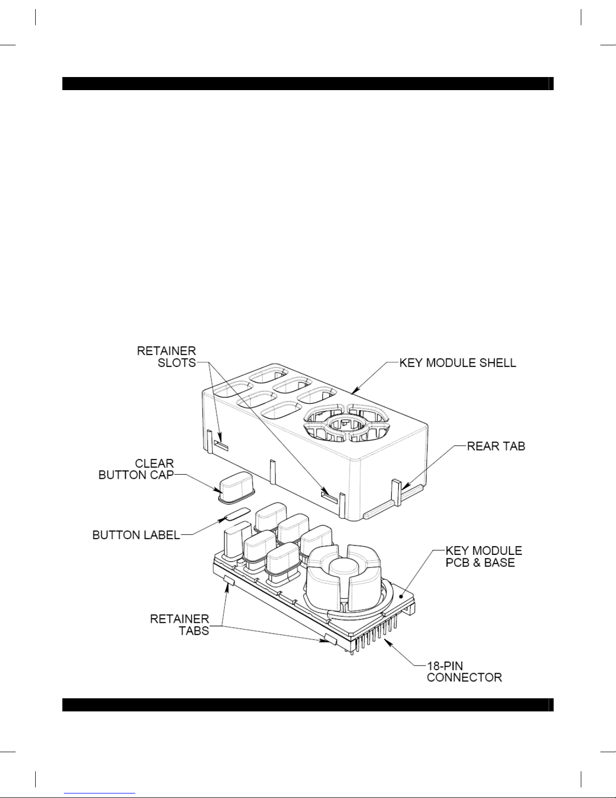
1. First, decide on the button labels you need and their locations.
2. Pick up the Key Module PCB & Base assembly and carefully place each button label onto the
Rubber Actuators in the location you desire.
3. When the button labels are completely in place, place the Clear Button Cap over the Button
Label and Rubber Actuators.
NOTE: As received from the factory, the Key Module Shell is separate
from the Key Module PCB & Base Assembly.
4. Pick up the Key Module Shell and lower it over the Key Module PCB & Base assembly.
5. Move the buttons slightly, as necessary, to align them so that they pass through the button
openings in the Key Module Shell.
6. Carefully press the Key Module Shell down until the 4 small Retainer Tabs on the Key
Module PCB & Base assembly snap into the corresponding Retainer Slots in the Key
Module Shell.
7. Mount the completed Key Module into the PM or LM or EM. Place the front tab of the Key
Module under the small lip of the LM, PM or EM. Align the 18-pin connector with the 18-pin
socket and carefully push into place.
Page 4

08905076A - 3 -
DISASSEMBLY
You may find it necessary, from time to time, to disable the Key Module to change buttons for
system updates, etc. Proceed as follows:
1. Remove the Key Module from the PM110 or LM110 or EM110 by pulling upward at the 18-pin
connector end of the module.
2. Grasp the Key Module with both hands, with the buttons facing you.
3. With the fingers of each hand, pull outward on the lower edges of the Key Module Shell.
4. As the 4 small retainer tabs recede from the slots on the Key Modules Shell, press down on
the buttons with your thumbs.
5. The Key Module Shell should now move away from the Key Module PCB & Base assembly.
CAUTION: To avoid damage, be sure not to use excessive force when
executing this disassembly procedure.
6. When you have made the desired button changes, reassemble the unit using the steps given
under INSTALLATION (section shown above).
Page 5

08905076A - 4 -
Xantech Corporation
13100 Telfair Avenue, 2/F
Sylmar, CA 91342
Phone: (818) 362-0353, Fax: (818) 362-9506
Instructions, CMD, KMD, MMD © 2007 Xantech Corporation
This document is copyright protected. No part of this manual may be copied or reproduced in any form without prior written consent from Xantech
Corporation.
Xantech Corporation shall not be liable for operational, technical, or editorial errors/omissions made in this document.
 Loading...