

Page 1
INSTALLATION INSTRUCTIONS
INJ94 & CPL94B
INJECTOR & COUPLER
TV
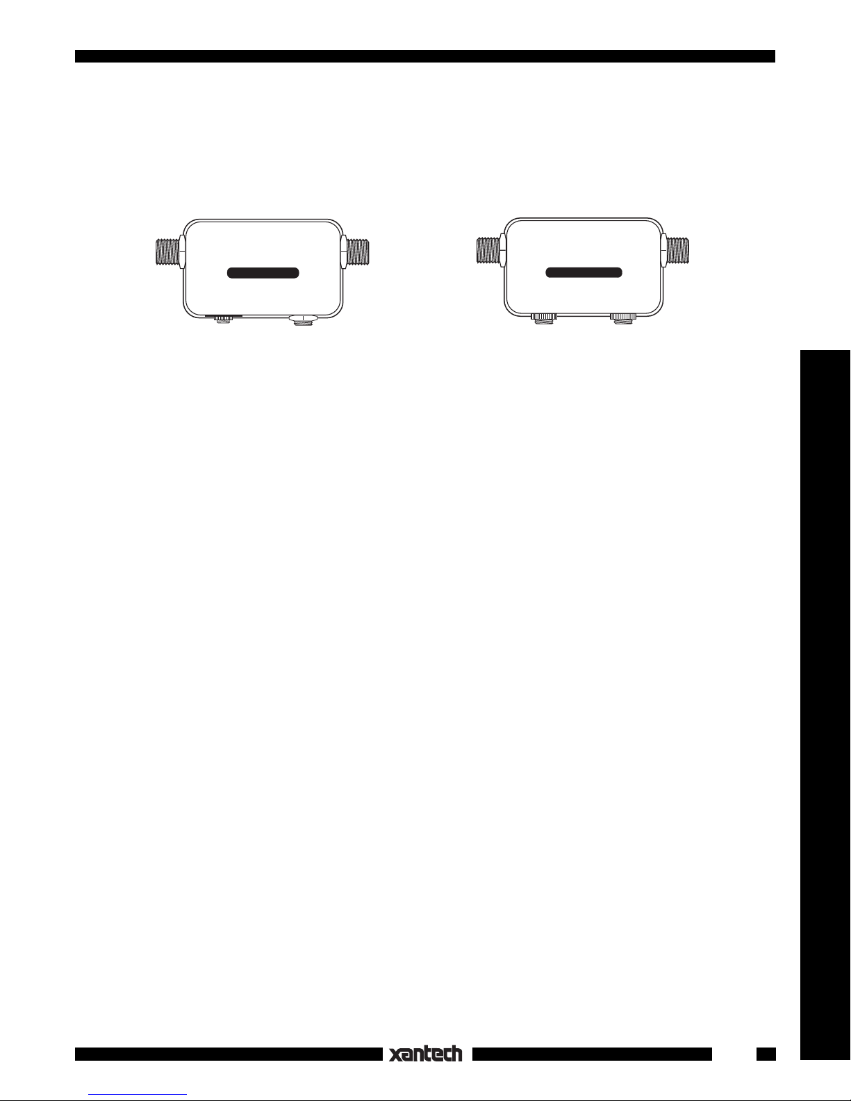
INJ94 INJECTOR
IR
RCVR
Fig.1 INJ94 Injector
+12 V
INPUT
SAT/VCR
CPL94B COUPLER
EMITTER
Fig.2 CPL94B Coupler
REMOTE TV
EMITTER
DESCRIPTION
The INJ94 injects and the CPL94B extracts IR control signals on the same coaxial cable that carries TV or
other RF signals, using the patented Xtra Link™ principle.
Located in Remote Rooms, the INJ94 injects the remote control signal into the room-to-room coaxial cable
(along with the TV signal) and passes it to a CPL94B or CPL10 Coupler in the Main Room or equipment
area. It is designed specifically so that Xantech IR Receivers having 3.5mm stereo mini plugs may be
plugged in directly to the IR RCVR jack. The 2.1mm +12 V coaxial jack also provides quick connection of
the Xantech 781RG power supply.
Located in the Main Room or equipment area, the CPL94B extracts the remote control signal from the
coaxial cable and passes it to the emitters that control the source equipment. Any of the Xantech single
or dual emitters may be plugged directly into the 3.5mm mono mini EMITTER jacks, in any combination,
for control of up to four components.
SPECIFICATIONS
INJ94 Injector:
• "F" coaxial connector jacks for TV and INPUT signals.
• 3.5mm IR RCVR stereo mini jack for quick connection of Xantech IR Receivers having 3.5mm stereo mini
plugs.
• 2.1mm +12 V jack for connection of the Xantech 781RG Power Supply.
• Dimensions: 2-3/16" x 1-3/8" x 7/8" (case).
CPL94B Coupler:
• "F" coaxial connector jacks for SAT/VCR and REMOTE TV signals.
• Two 3.5mm EMITTER mono mini jacks, with 470 Ohm series resistors, for quick connection of two
Xantech single or dual emitters.
• Dimensions: 2-3/16" x 1-3/8" x 7/8" (case).
Accessories
INSTALLATION
FIG. 3 illustrates a typical installation using two INJ94's and a CPL94B in a three room system.
When configuring these types of systems, keep the following factors in mind:
1. Room-to-room coaxial cable lengths, exclusive of RF signal considerations, may be up to one mile in
length, using RG-6, for successful IR signal transmission.
2. When configuring multiple rooms, be sure the RF splitters used are DC passing types, such as Xantech
Models 200-00 (2-way) and 202-00 (4-way). Refer to Figs. 3 and 4.
1
Page 2

Satellite Dish
TV SIGNAL PATH
IR REMOTE CONTROL PATH
IR RECEIVER
Hand Held
Remote
REMOTE ROOM 2
RF IN OUT TO TV
Coaxial Cable
RF IN
OUT TO TV
291-00
2ND
TV
Coaxial Cable
SATELLITE
RECEIVER
(Back Panel)
IR Sensor Windows
(Front Panel)
(Back Panel)
RF IN
VCR
Coaxial Cable
Coaxial Cable
Emitter
Emitter
INJ94
TV
INJ94 INJECTOR
IR
RCVR
781RG
Power Supply
To 120 V AC
(unswitched)
Place emitters on
the IR sensor
window on front
panel of each
controlled unit.
286M
Mouse Emitter Assembly
INJECTOR
INPUT
+12 V
Dual Blink-IR™
Hand Held
Remote
REMOTE ROOM 1
Coaxial
Cable
200-00
2-Way
RF Splitter
OUT
IN
OUT
MAIN ROOM
291-00
IR RECEIVER
3RD
TV
CPL94B
COUPLER
(included)
SAT/VCR
CPL94B COUPLER
EMITTER
RF IN
REMOTE TV
EMITTER
Spare jack
for additional
emitter(s),
if needed.
Coaxial Cable
INJ94
INJECTOR
TV
INJ94 INJECTOR
IR
RCVR
Coaxial Cable
781RG
Power Supply
To 120 V AC
(unswitched)
Room-to-Room Coaxial Cables
OUT
OUT
IN
2-Way RF Splitter
Coaxial Cable
RF IN
INPUT
+12 V
200-00
DC Passing
Local
TV
Fig. 3 A Typical 3-Room System
ADVANCED MULTIROOM SYSTEMS
Fig. 4 illustrates an advanced system using a variety of connection and control techniques typical of
complex multiroom installations. It is configured as follows:
1. Both INJ94 Injectors and CPL10 Couplers are used in the remote rooms with various Xantech IR
Receivers.
As a rule of thumb, use the CPL10 with the CB12 Connecting Block when using Xantech 3-terminal
IR receivers or keypads, such as the 480-00 Dinky Link, 730-00 Smart Pad, etc. Use the INJ94 when
using Xantech IR receivers equipped with a 3.5mm quick-connect stereo mini plug, such as the 29100 Hidden Link and the 490-30 Micro Link.
2. Each IR receiver must be locally powered by a 781RG Power Supply as shown.
3. IR RCVR jack connections for the INJ94.Should you wish to make your own
custom connections to a mating 3.5mm stereo mini plug for this jack, follow the
terminal identifications given in the table, Fig.5.
4. Note that model 203-00 DC Blockers are used on the two coax leads going to
not
the two TV sets in the rooms
having IR receivers. This is a
must
to prevent
PLUG
RING
TIP
SLEEVE
Fig.5
CIRCUIT ITEM
GROUND
SIGNAL
+ 12 V
the RF inputs on the two TV sets from "shorting out" the IR control signal.
5. If an RF amplifier(s) is used anywhere in the line of coaxial cable between the CPL94B Coupler and
must
the INJ94 or CPL10 Injectors, you
use a Xantech BYPASS94 KIT to route the IR control signals
around the amplifier(s).
Where possible, place RF amplifiers ahead of the CPL94B Coupler, as shown in Fig. 4, instead of
using a bypass kit.
6. Fig. 4 shows four components being controlled using two 286-00 dual emitters. This is the maximum
number of components controllable with the CPL94B. If you wish to control more, use the CPL10
2
INJ94/CPL94
Page 3

instead, along with a suitable connecting block, such as the 789-44 or 791-44.
See the CPL10 installation instructions
for details.
480-00
Six Remote Rooms, each configured with IR receivers.
480-00 480-00
TV
291-80
TV TV
291-10
490-30
Two Remote Rooms
not
configured
with IR receivers.
(See item 4, pg 4).
7. For information on how to connect and
configure modulators and RF amplifi-
®
ers, refer to ChannelPlus
technical in-
CB12
TV TV TV
CB12
CB12
formation.
TV
TROUBLE SHOOTING
1. Perhaps the most common problem is
RF
IR
CPL10
RF/IR
TV
RCVR
IR
INJ94
+12 V
INPUT
RF
IR
CPL10
RF/IR
TV
RCVR
IR
INJ94
+12 V
INPUT
RF
IR
CPL10
RF/IR
TV
RCVR
IR
INJ94
+12 V
INPUT
stray IR or RF interference entering IR
receivers, preventing proper operation
of the controlled equipment.
Examples of such interference are:
• Fluorescent, Compact Fluorescent,
Neon or Halogen lights, Neon Art, or
781RG
Powe r
Supplies (6)
INJ94
Injectors (3)
CPL10
Couplers (3)
202-00
4-way RF Splitters
DC Passing
light dimmers.
• Direct or reflected sunlight.
• Infrared security sensors (active type).
• RF radiation from TV sets that may be
close to IR Receivers.
It may be necessary to move either the
interfering source or the IR receiver to
achieve proper operation. Sometimes
RF Signal
IR Signal
CPL94B
Coupler
(1 location)
REMOTE TV
SAT/VCR
CPL94B COUPLER
2-way RF splitter
EMITTER
EMITTER
200-00
DC Passing
203-00
DC Blockers (2).
(See item 4, pg 4).
the Xantech Sun Filters will help.
2. If the IR receivers must operate in the
vicinity of electronically ballasted Compact Fluorescent lamps or sunlight con-
RF
AMP
IN OUT
ditions, use Xantech models 291-80 or
780-80 IR receivers. These are specifically designed to reject most of this type
ofinterference.
3. Check for shorts or opens anywhere
between the IR receivers in the remote
286M
Dual Blink-IR™
Mouse Emitter Assembly
Modulator
(3-Input)
A/V Patch
Cords
2512
2-way
Combiner
286M
Dual Blink-IR™
Mouse Emitter
Assembly
rooms and the emitters at the controlled
equipment.
Satellite Receiver Laser Disc Player
VCR Cable Box
•Remember, you must have DC conti nuity all the way from the IR (IR RCVR)
Fig. 4 Advanced Multiroom System
jacks on the Injectors, through the coax
cables to the IR (emitter) jack on the coupler, without shorts to ground.
TM
• Use a Xantech Test-IR
plugged into the IR (emitter) jack on the coupler to verify that the IR
signal is being received from each room.
• If necessary, use a multimeter in the low Ohms range to check for continuity, shorts, opens, etc.
• Check for open emitters by substituting a known good emitter.
4. If a given component still does not work, reposition the emitter. It may not be located directly over the
component’s IR (infrared) receiving "window". Consult the owner's manual of the unit or the
manufacturer for the exact location of the infrared "window".
12-7-00
Rev.C
INJ94/CPL94
3
TV
Accessories
 Loading...