

Page 1
Incandescent Dimmer Switch - Receiver
XPD3
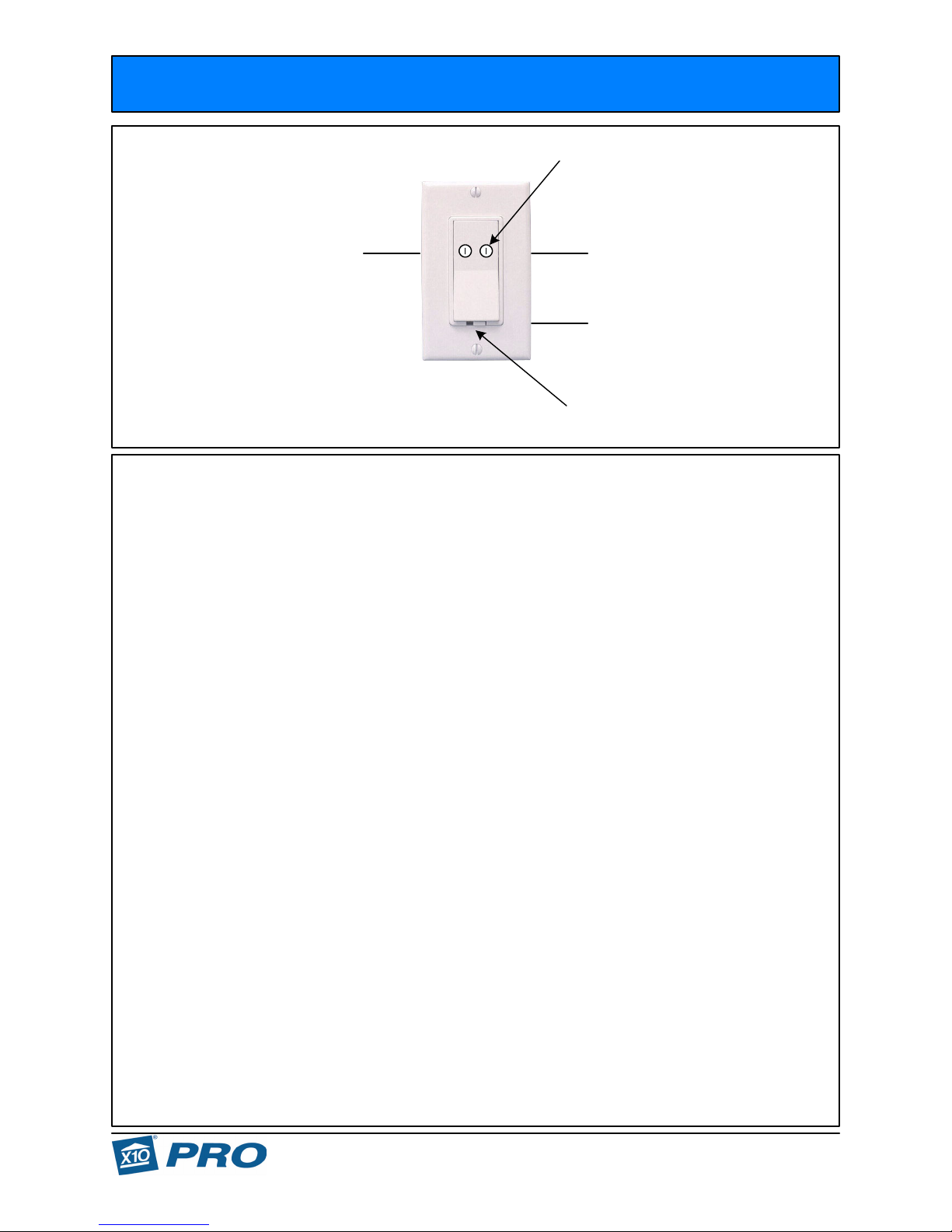
Single-Pole Switch
Dials Behind
Rocker
A
Switched Leg
to Light
A1
1
XPD3
Master
ONOFF
RedBlue
(CONTROL)
Black
Power
Cutoff
No Connection
HOT
(Black)
Switch
Description:
The XPD3 is an Incandescent, decorative-style, dimming, Single-Pole/3-Way Master Wall Switch rated for 40-500watts.
It can handle loads as follows: Incandescent Bulbs only (i.e. 120V Standard or 120V Halogen). The decorative paddle permits local operation of
ON/OFF and Bright/Dim of the lighting load. The Power Cutoff Switch is provided for bulb changing. The X10 Address Code Dials for setting the
Letter Code and Number Code are located behind the paddle.
Specific Requirements: 120VAC, 40-500W Incandescent ONLY. Lamps rated below 40W may flicker and/or operate erratically.
DO NOT use with: Fluorescent Lighting, Low Voltage Lighting (which use Inductive Transformers), ceiling fan motors, etc.
Optional / Supplementary Devices & Modules:
XPDP-AL - Almond Rocker in Pkg of 10ea.
XPSS - Slave Switch for existing 3-Way Installations. Uses XPSP-AL Almond rockers.
XPT2D - Alternate Slave Switch (Transmitter) for existing and creating new 3-Way/4-way Installations.
X10 Protocol:
House Code Dial - Letters A-P (default "A") Unit Number Dial - Numbers 1-16 (default "1")
Each X10 Receiver Module is set to a unique Unit Number or to an identical Unit Number as desired.
Each X10 Controller operating a specific set of Receiver Modules must be set to the same Letter Code as the Receivers they are controlling.
Responds to ALL LIGHTS ON command. Full Dimming capability with Incandescent lighting.
Electrical Protocol:
Nearly all residential homes are wired SPLIT-PHASE. Each 120V Phase is NOT directly connected with the other 120V phase. If after installation,
an X10 Receiver does not respond to a remote Controller, then check to ensure that the breaker serving the X10 Receiver is on the same phase as
the Controller. If not, the breaker can be changed to the opposite phase. An alternative solution is recommended, to install a Phase Coupler for
improving remote communications throughout the home. See www.x10pro.com, then select Technical Support and PLC Troubleshooting.
Installation: for Single-Pole operation
1. Turn power OFF at Circuit Breaker.
2. Pull-out the existing wall switch from the switch box.
3. On the XPD3, Cap off the RED wire, it will not be used in this install.
4. Remove the existing wall switch. Two wires remain, one is HOT, the other goes to the light/load. They may be the same color.
5. With Breaker ON, determine which protruding wire is HOT. Use a voltmeter and measure between ground and each wire individually.
One will read 120V, the other 0V.
6. With Breaker OFF, connect the HOT wire to the BLACK wire, connect the Light/Load wire to the BLUE wire.
7. Re-check all connections, Turn power ON at Circuit Breaker. Slide the Power Cutoff Switch to ON position.
8. Press rocker paddle once, the light should turn ON. Press & Hold to Dim the light/load. Press paddle again, the light should turn OFF.
9. You are now ready to control the switch with an X10 Remote Control Module: Desktop, Wireless Handheld, Security Panel, etc. The default
address is "A1". If you wish to change the Address Code, the Code Dials are behind the paddle. Remove the paddle with a small flat screwdriver
applied to the side of the paddle at the center fulcrum point. Insert screwdriver in the small gap space between switch plate and paddle and flip the
paddle up from its side.
10. Attach the switch cover plate.
Soft Start On and Fade Off plus Bright / Dim Control:
On/Off - A short paddle press causes the Switch to come on at full dim and fade up to the full intensity, another short paddle press causes the
Switch to fade off (brightening to full intensity and fading to full off takes approx 3 seconds each direction).
Dimming from ON - Press and hold to achieve the dim level desired then release. When released, the direction of dimming is toggled, (i.e.
next press and hold will cause the switch to brighten). A short paddle press from any dimmed level will fade off the Switch. A dimmed Switch
will resume the level of intensity when turned back on
Note: If you would like the Switch to always resume full intensity when turned on, then press and hold the paddle until the Switch attains full
brightness before releasing. Then a short paddle press will fade off.
Additionally, any X10 Controller can remotely operate the full functions of the Switch.
(i.e. if dimmed to 50% then turned off, the Switch will resume at 50% when turned back on).
Tampa, FL 33542
XPD3_04_05/08
Technical Support: (800) 832-4003
Page 2
Incandescent Dimmer Switch - Receiver
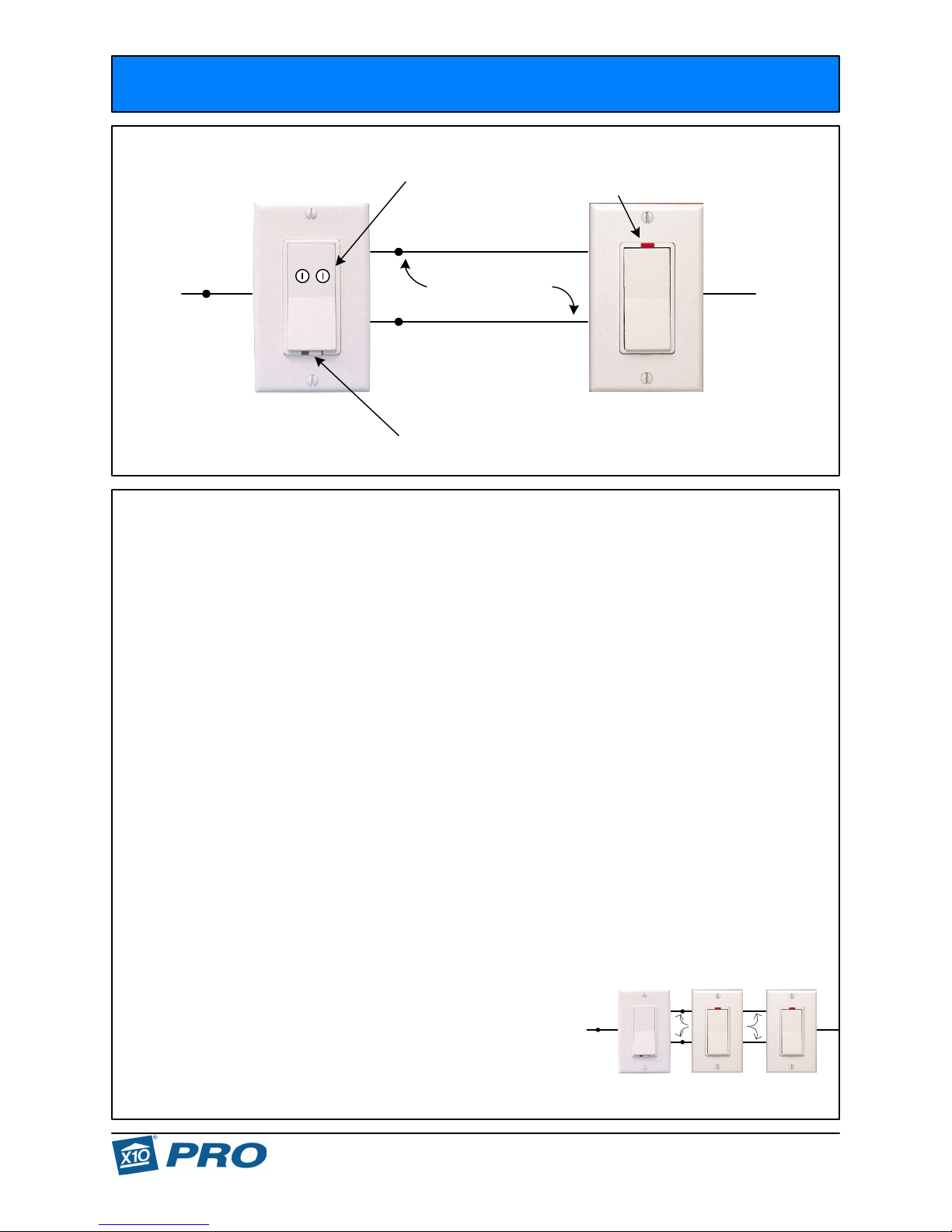
3-Way Installation - Existing
Dials Behind
Rocker
In-Active
LED
XPD3
Switched Leg
Red
A1
SWITCH
to Light
Blue
Traveler Wires
LIVE
HOT
(Black)
Black LIVE
ONOFF
XPD3
Master
Installation: for 3-Way operation - Existing
Note: A 3-Way system, by definition, means two existing wall switches which operate one single light (can be multiple lights if all come
on together).
1. Turn power OFF at Circuit Breaker.
2. Pull-out the existing 3-way wall switches from the two switch boxes.
3. Remove the common-side wire (by itself) from the two switches. In one switch box, that single wire is HOT, in the other switch box, that single
wire goes to the light.
4. With Breaker ON, determine which wire is HOT. Use a voltmeter and measure between ground and each single wire individually. One will read
120V, the other 0V. With Breaker OFF, mark the single wires as to which one is HOT and which one goes to the light.
5. The Slave Switch is installed in the switch box which has the HOT wire. The Master Switch is installed in the switch box that has the wire that
goes to the light.
7. With Breaker OFF, remove the existing two wall switches. Three wires (minimum) remain protruding out of each switch box. At the Slave switch
box, one is HOT, the other two wires are the traveler wires. At the Master switch box, one is the Light/Load wire, the other two wires are the traveler
wires.
8. With Breaker OFF, install the Slave Switch first. HOT wire goes to LIVE (either screw, they are a common bus), One Traveler wire also goes to
LIVE, the second Traveler wire goes to SWITCH.
9. With Breaker OFF, install the Master Switch second. The One HOT Traveler wire goes to BLACK wire, the second Traveler wire goes to RED
wire. The Light wire goes to BLUE wire.
10. Re-check all connections, Turn power ON at Circuit Breaker. Turn the Power Cutoff Switch to ON position.
11. Press Master Switch paddle once, the light should turn ON. Press paddle again, the light should turn OFF. Press the Slave Switch paddle
once, and the light should turn ON. Press the Slave Switch paddle again, and the light should turn OFF.
12. You are now ready to control the switch with an X10 Remote Control Module: Desktop, Wireless Handheld, Security Panel, etc. The default
address is "A1". If you wish to change the Address Code, the Code Dials are behind the paddle. Remove the paddle with a small flat screwdriver
applied to the side of the paddle at the center fulcrum point. Insert screwdriver in small gap space between switch plate and paddle and flip the
paddle up from its side.
13. Attach the switch cover plate. Full On/Off and Bright/Dim functions are operated from all the Switches in the circuit.
Soft Start On and Fade Off plus Bright / Dim Control:
On/Off - A short paddle press causes the Switch to come on at full dim and fade up to the full intensity, another short paddle press causes the
Switch to fade off (brightening to full intensity and fading to full off takes approx 3 seconds each direction).
Dimming from ON - Press and hold to achieve the dim level desired then release. When released, the direction of dimming is toggled, (i.e.
next press and hold will cause the switch to brighten). A short paddle press from any dimmed level will fade off the Switch. A dimmed Switch
will resume the level of intensity when turned back on
Note: If you would like the Switch to always resume full intensity when turned on, then press and hold the paddle until the Switch attains full
brightness before releasing. Then a short paddle press will fade off.
Additionally, any X10 Controller can remotely operate the full functions of the Switch.
Note: 4-Way circuits can be replaced using the XPD3 and two (2) XPSS Slave Switches.
This picture represents the switches in a "3-Way - 4-Way - 3-Way" circuit.
Simply connect an XPSS in the middle box (noted by 4 wires removed from the existing 4-Way switch):
1. Connect the 2 traveler wires that make connection from the Switch connection on the first
XPSS Slave and the Red wire connection on the XPD3 Master, both to the Switch terminal on this 4-Way XPSS.
2. Connect the 2 traveler wires that make connection from the Live connection on the first
XPSS Slave and the Black wire connection on the XPD3 Master, both to the Live terminal on this 4-Way XPSS.
(HOT)
Power
Cutoff
Switch
(i.e. if dimmed to 50% then turned off, the Switch will resume at 50% when turned back on).
Switched Leg
to Light
Blue
XPSS
Slave
XPD3
Master
Red
Black
SWITCH
Traveler Wires
LIVE
XPSS
Slave
LIVE
SWITCH
LIVE
XPSS
Slave
HOT
(Black)
LIVE
Tampa, FL 33542
XPD3_04_05/08
Technical Support: (800) 832-4003
Page 3

Incandescent Dimmer Switch - Receiver
3-Way Installation - Existing/Alternate
Dials Behind
Rocker
XPD3
Neutral
(White)
Switched Leg
Red
A1
no connection
White
1
to Light
Blue
Black
ONOFF
Power
Cutoff
XPD3
Master
Switch
Installation: for 3-Way / 4-Way operation - Existing/Alternate
Note: A 3-Way / 4-Way system, by definition, means two or more existing wall switches which operate one single light (can be multiple
lights if all come on together). In this alternate installation instruction, the XPSS switch may not work well due to longer traveler wires
between multiple switches. The XPT2D Transmitter will work over the longer wires between multiple switches.
The XPT2D Transmitter provides ON/OFF and Bright/Dim.
1. Turn power OFF at Circuit Breaker.
2. Pull-out the existing 3-way wall switches from the two switch boxes.
3. Remove the common-side wire (by itself) from the two switches. In one switch box, that single wire is HOT, in the other switch box, that single
wire goes to the light.
4. With Breaker ON, determine which wire is HOT. Use a voltmeter and measure between ground and each wire individually. One will read 120V,
the other 0V. With Breaker OFF, mark the wires as to which one is HOT and which one goes to the light.
5. The Alternate XPT2D Transmitter is installed in the switch box which has the HOT wire. The Master Switch is installed in the switch box that has
the wire that goes to the light.
6. With Breaker OFF, remove the existing two wall switches. Three wires (minimum) remain protruding out of each switch box. At the Slave switch
box, one is HOT, the other two wires are the traveler wires. They may be the same color, normally they are different colors. At the Master switch
box, one is the Light/Load wire, the other two wires are the traveler wires. They may be the same color, normally they are different colors.
7. With Breaker OFF, install the Alternate XPT2D Transmitter first. The HOT wire goes to the XPT2D Black wire bundled with one Traveler wire
(this will carry HOT to the Master Switch), the White wire of the XPT2D is connected to a White Neutral Wire in the same box.
8. With Breaker OFF, install the Master Switch second. The One HOT Traveler wire goes to BLACK wire. The Light/Load wire goes to BLUE wire.
9. Re-check all connections, Turn power ON at Circuit Breaker. Slide the Power Cutoff Switch to ON position.
10. Press Master Switch paddle once, the light should turn ON. Press paddle again, the light should turn OFF. Press the alternate XPT2D
Transmitter "ON" position once, and the light should turn ON. Press the alternate XPT2D Transmitter "OFF" position once, and the light should turn
OFF. Additionally you can press the DIM or Brighten rocker on the alternate XPT2D Transmitter to control intensity after you turn the load on.
11. You are now ready to control the switch with an X10 Remote Control Module: Desktop, Wireless Handheld, Security Panel, etc. The default
address is "A1" for both switches. If you wish to change the Address Code, the Code Dials are behind the paddle on the Master and Keypad on the
Transmitter. Remove the paddle with a small flat screwdriver applied to the side of the paddle at the center fulcrum point. Insert screwdriver in
small gap space between switch plate and paddle and flip the paddle up from its side.
Remove the Keypad, with fingers pulling from bottom, to change the XPT2D Address Code.
12. Attach the switch cover plate.
Soft Start On and Fade Off plus Bright / Dim Control:
On/Off - A short paddle press causes the Switch to come on at full dim and fade up to the full intensity, another short paddle press causes the
Switch to fade off (brightening to full intensity and fading to full off takes approx 3 seconds each direction).
Dimming from ON - Press and hold to achieve the dim level desired then release. When released, the direction of dimming is toggled, (i.e.
next press and hold will cause the switch to brighten). A short paddle press from any dimmed level will fade off the Switch. A dimmed Switch
will resume the level of intensity when turned back on
Note: If you would like the Switch to always resume full intensity when turned on, then press and hold the paddle until the Switch attains full
brightness before releasing. Then a short paddle press will fade off.
Additionally, any X10 Controller can remotely operate the full functions of the Switch.
Note: You can use additional XPT2D Wall Transmitter Switches to augment EXISTING 4-Way or greater systems. Continue using the existing
traveler wires to carry HOT and Neutral to the additional existing Switch Box locations. Then install the XPT2D in those additional boxes with
traveler wires, connecting to HOT and Neutral.
Traveler Wire
HOT
Note: both switches
set to same Address
Code
(i.e. if dimmed to 50% then turned off, the Switch will resume at 50% when turned back on).
Alternate Slave
A
XPT2D
Black
HOT
(Black)
Tampa, FL 33542
XPD3_04_05/08
Technical Support: (800) 832-4003
Page 4

Incandescent Dimmer Switch - Receiver
XPD3
3-Way Installation - Create New (when there are no traveler wires available between boxes)
Dials Behind
Rocker
White
Switched Leg
to Light
Blue
Red
A1
no connection
1
A
Black
NEUTRAL
(White)
HOT
(Black)
Black
Note: both switches
set to same Address
ONOFF
XPD3
HOT
Master
(Black)
Installation: for 3-Way operation - Create New (when there are no traveler wires available between boxes)
Note: A 3-Way / 4-Way system, by definition, means two or more existing wall switches which operate one single light (can be multiple
lights if all come on together). In this Create NEW installation instruction, there are no traveler wires between switches. The XPT 2D
Transmitter will be connected to HOT and NEUTRAL only. It will communicate with the Master Switch via existing power wires.
The XPT2D provides ON/OFF and Bright/Dim.
1. Turn power OFF at Circuit Breaker.
2. With Breaker OFF, remove the existing wall switch. Two wires remain protruding out of switch box. One is HOT, the other goes to the light/load.
They may be the same color.
3. With Breaker ON, determine which wire is HOT. Use a voltmeter and measure between ground and each wire individually. One will read 120V,
the other 0V.
4. With Breaker OFF, connect the HOT wire to the Black wire, connect the Light/Load wire to the BLUE wire. Cap off the Red wire.
5. Re-check all connections, Turn power ON at Circuit Breaker. Turn the Power Cutoff Switch to ON position.
6. Press switch paddle once, the light should turn ON. Press paddle again, the light should turn OFF.
7. You are now ready to control the switch with an X10 Remote Control Module: Desktop, Wireless Handheld, Security Panel, etc. The default
address is "A1". If you wish to change the Address Code, the Code Dials are behind the paddle. Remove the paddle with a small flat screwdriver
applied to the side of the paddle at the center fulcrum point. Insert screwdriver in small gap space between switch plate and paddle and flip the
paddle up from its side.
8. Install the XPT2D Wall Transmitter Switch. You will need an existing or new switch box which has power run to it.
9. With Breaker OFF, connect the XPT2D Transmitter Black wire to HOT, connect the XPT2D Transmitter white wire to Neutral. Turn Breaker ON.
10. Press the XPT2D Transmitter Switch "ON" position once, and the light should turn ON. Press the XPT2D Transmitter Switch "OFF" position
once, and the light should turn OFF.
11. To change the XPT2D Address Code, remove the Keypad, with fingers pulling from bottom, then turn the dials, with small flat screwdriver, to the
desired Address Code. Keep the XPD3 and XPT2D Address Codes identical.
12. Attach the switch cover plates.
Soft Start On and Fade Off plus Bright / Dim Control:
On/Off - A short paddle press causes the Switch to come on at full dim and fade up to the full intensity, another short paddle press causes the
Switch to fade off (brightening to full intensity and fading to full off takes approx 3 seconds each direction).
Dimming from ON - Press and hold to achieve the dim level desired then release. When released, the direction of dimming is toggled, (i.e.
next press and hold will cause the switch to brighten). A short paddle press from any dimmed level will fade off the Switch. A dimmed Switch
will resume the level of intensity when turned back on
Note: If you would like the Switch to always resume full intensity when turned on, then press and hold the paddle until the Switch attains full
brightness before releasing. Then a short paddle press will fade off.
Additionally, any X10 Controller can remotely operate the full functions of the Switch.
Note: You can use additional XPT2D Wall Transmitter Switches to augment EXISTING 4-Way or greater systems. Continue using the existing
traveler wires to carry HOT and Neutral to the additional existing Switch Box locations. Then install the XPT2D in those additional boxes with
traveler wires, connecting to HOT and Neutral.
Code
Power
Cutoff
Switch
(i.e. if dimmed to 50% then turned off, the Switch will resume at 50% when turned back on).
XPT2D
Alternate Slave
: You can use additional XPT2D Wall Transmitter Switches to augment NEW 4-Way or greater systems (when there are no traveler wires
Note
available between boxes). You will need additional wall switch boxes with power run to them. Then install the XPT2D, connecting HOT and Neutral.
Tampa, FL 33542
XPD3_04_05/08
Technical Support: (800) 832-4003
 Loading...