

Page 1
Single & 3-Way Decorator Wall Dimmer Set Up and Operating Instructions WS12A/WS14A
Cap off with
wire nut
AB
The WS12A Wall Dimmer Module is designed to control incandescent loads with a rating of between 40W and 500W. Lamps rated
below 40W may flicker or operate erratically. The switch can replace a single switch that controls a ceiling light or outside light. It can
also be used where two switches control the same light (3-way). In this case a Companion Switch (WS14A) is required and is sold
separately. A push-button is provided on each switch for local on/off control and local dimming. (See WS14A instructions for 4-way
applications).
WARNING: W all Dimmer Modules must not be used to control appliances or fluorescent lamps.
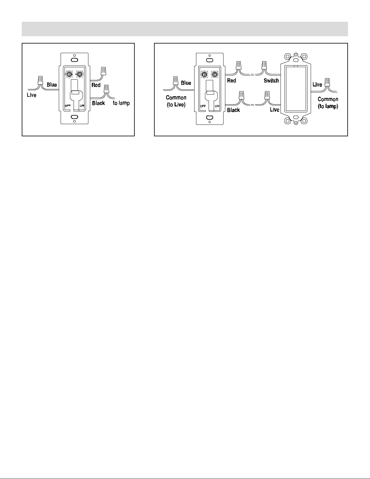
Installing the Wall Dimmer Module (single switch applications, diagram A)
• Disconnect the power at the circuit breaker panel.
• Remove the wall plate and unscrew the existing switch from its box.
• Remove the two wires from the existing switch and connect them to the two wires on the WS12A, using the wire nuts provided.
• Cap off the unused red wire with a wire nut (supplied). Make sure no bare whiskers of wire are protruding, use insulating tape to
cover wire nuts if necessary. Screw the switch into the wall box. Don't replace the wall plate yet.
Installing the Wall Dimmer Module (3-way applications, diagram B)
• Disconnect the power at the circuit breaker panel.
• Remove wall plates and unscrew the existing switches from their boxes. Identify the common wire at each existing switch
(usually connected to a different color terminal).
• Replace one of the existing wall switches with the WS12A Wall Dimmer (Master): connect the common wire to the blue wire on
the WS12A using a wire nut. Connect the two remaining "traveller wires" to the red and black wires on the WS12A, using wire
nuts. If one of the travellers is red connect it to the red wire on the WS12A.
• Replace the other existing wall switch with the WS14A Companion Switch (sold separately): connect the common wire to one of
the WS14A's terminals labelled LIVE. Connect the traveller which you connected to the red wire on the WS12A to the terminal
labelled SWITCH on the WS14A. Connect the remaining traveller wire to the second terminal labelled LIVE on the WS14A. Screw
both switches into their wall boxes. Don't replace the wall platet yet.
Setting up and operating the Wall Dimmer Module
• Pop the rocker paddle off the WS12A (using a small screwdriver). Set the House Code dial to the same letter (A thru P) that you
set on your X10 controller(s).
• Set the Unit Code dial to an unused code (1 - 16) which can be controlled from any X10 controller.
• Set the power on-off slide switch (under the rocker paddle) to the ON (right) position. Turn this switch OFF (left) when changing a
light bulb. Replace the paddle.
• Refit the wall plates on both switches.
• Turn the power back on at the circuit breaker panel.
• Press the paddle quickly to turn the module on and off. Press and hold to dim or brighten. Note: if you press the paddle and
nothing happens, you might have pressed it for too long and started to dim the light and not noticed that it dimmed.
• You can turn the module on and off and dim and brighten it remotely from any X10 Controller.
LIMITED 1-YEAR WARRANTY
WS12A
X10.com, a division of X10 Wireless Technology, Inc. (X10) warrants X10 products to be free from
Traveller
WS12A
Master
wires
WS14A
Companion
defective material and workmanship for a period of one (1) year from the original date of purchase at retail. X10 agrees to
repair or replace, at it’s sole discretion, a defective X10 product if returned to X10 within the warranty period and with proof of
purchase. If service is required under this warranty:
Call 1-800-442-5065, visit www.x10.com, or e-mail sales@x10.com.
X10.com, a division of X10 Wireless T echnology, Inc. http://www.x10.com/support
WS12A -10/02
 Loading...