

Page 1
II
NDOORNDOOR
NDOOR
I
NDOORNDOOR
II
/O/O
UTDOORUTDOOR
UTDOOR
/O
UTDOORUTDOOR
/O/O
C C
C
C C
OLOROLOR
OLOR
OLOROLOR
CC
AMERAAMERA
AMERA
C
AMERAAMERA
CC
GHGH
GH
GHGH
MM
M
MM
FF
LOODLIGHTLOODLIGHT
LOODLIGHT
F
LOODLIGHTLOODLIGHT
FF
ZZ
Z
ZZ
OO
TIONTION
O
TION
OO
TIONTION
W W
W
W W
S S
S
S S
WITHWITH
WITH
WITHWITH
IRELESSIRELESS
IRELESS
IRELESSIRELESS
ENSORENSOR
ENSOR
ENSORENSOR
B B
B
B B
L L
L
L L
UILUIL
UIL
UILUIL
T T
T
T T
,,
,
,,
AMPAMP
AMP
AMPAMP
--
TT
T
TT
RANSMITTERRANSMITTER
RANSMITTER
RANSMITTERRANSMITTER
ANDAND
AND
ANDAND
H H
H
H H
2.4 2.4
ININ
IN
-
2.4
ININ
--
2.4 2.4
DUDU
ALAL
DU
DUDU
AL
ALAL
OLDERSOLDERS
OLDERS
OLDERSOLDERS
,,
,
,,
MODEL VT38A OWNER'S MANUAL
Page 2
INTRODUCTION
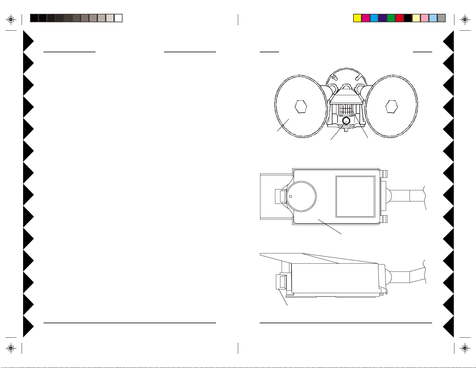
FRONT, BOTTOM, & SIDE VIEWS
Y our W ireless Motion Activated Camera with Dual Floodlights consists of a
Color Video Camera with built-in 2.4 GHz transmitter. It is activated by its
built-in Motion Sensor so that when someone approaches your home, the
camera turns on. At night the connected floodlights also turn on with motion
to light up the area that the camera sees (bulbs not included). The camera
transmits its picture via its built-in 2.4 GHz transmitter, to a V ideo Receiver
(sold separately) which you connect to a TV anywhere in your home. The
Camera sends the wireless signals (even through walls, up to 100 ft.). The
Video Receiver converts the signals back to video signals and feeds them
through a cable to your TV's Video input.
You can purchase additional Motion Activated Cameras (up to 4) so you
can have a multiple camera system. You can then set all cameras to the
same channel as the receiver and turn the cameras on and off with X10
remote controls (sold separately) so as to only have one camera turned on
at a time, and displayed on your TV.
FRONT VIEW
Bulbs not
included
Camera
BOTTOM VIEW (WITH LID CLOSED)
IDE VIEW
S
Motion Sensor
Controls under this
weatherproof lid.
Remove clear cap if you need to refocus the
camera. Replace to keep rain out.
22
2
22
33
3
33
Page 3
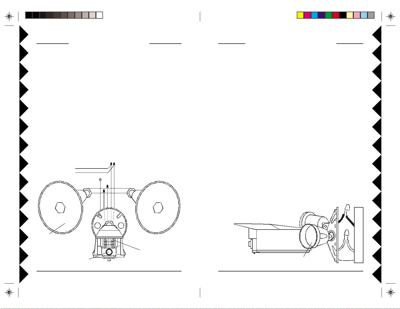
ASSEMBLING THE PARTS
INSTALLING THE ASSEMBLY
Referring to the diagram below:
1. Screw the base of each lamp holder into the outer holes on the mounting
plate.
2. Rotate the locking ring on each lamp holder towards the plate until the
lamp holder is secure against the plate.
3. Screw the threaded end of the motion activated camera into the center
hole on the mounting plate.
4. Lock the motion activated camera into place using the locking ring.
5. Locate each lamp holder’s WHITE wire and one of the WHITE wires
from the motion activated camera and twist all three wires together
using a wire nut (supplied).
6. Locate each BLACK wire from the lamp holders and connect them
both to the BLUE wire from the motion activated camera, again using a
wire nut.
7. Make sure no bare whiskers of wire stick out from the wire nuts (cover
with electrical tape if necessary).
Whi te (N eutral)
Black (Live)
House W iring
Wal l Box Groungi ng Scre w
White
Black
White
Black
Green
Whi te
White
Blue
Black
Y ou can install the Motion Activated Camera in a wall box that is powered
at all times or in a wall box that is controlled by a wall switch, but if it is
controlled by a wall switch, make sure you leave the switch on at all times.
Turning the switch of f will completely disable the motion activated camera.
CAUTION: To prevent severe damage to the unit, do not connect it to a
wall box that is controlled by any kind of dimmer or remote controlled
switch.
WARNING: Before making the following connections, be sure the
power to the junction box you are installing the motion activated
camera into is turned off. If not, a serious shock hazard will exist.
1. Install the gasket (supplied) onto the junction box, and route the house
wiring through the gasket.
2. Connect the GREEN wire from the mounting plate to the bare ground
wire in the junction box, or ground screw if there is one.
3. Connect the WHITE (Neutral) wire from the motion activated camera
assembly to the house wiring’s WHITE (Neutral) wire, using a wire nut.
4. Connect the BLACK (Live) wire from the motion activated camera
assembly to the house wiring’s BLACK (Live) wire, using a wire nut.
5. Make sure no bare whiskers of wire stick out from the wire nuts (cover
with electrical tape if necessary).
6. Secure the mounting plate to the junction box using the screws supplied.
7. Secure the insulating ring in each lamp holder and screw a bulb (max.
150W , not supplied) into each lamp holder .
Bulbs not
included
Camera
Live
Motion Sensor
Neutral
Insulating ring
44
4
44
55
5
55
Ground
Page 4

CAMERA MODE
Auto
A
CHANNEL
Set to same letter
as your receiver
C
B
D
TIME DELAY
UNIT CODE
HOUSE CODE
DARK
MAX.
LIGHT
MIN.
1
3
5
7
9
A
CO
M
E
G
I
K
remote controls and
Transceiver
RECEIVER INSTALLATION
CONNECTING UP THE RECEIVER
(SOLD SEP A RATELY )
1. Connect a video cable to the VIDEO
OUT jack on the VR36A Video
Receiver. Connect the other end to
your TV's VIDEO IN jack. If your TV
does not have a Video IN jack, you will
need to purchase an RF modulator, or
connect as shown in the diagram below.
2. Plug the Video Receiver’s power
supply jack into the Video Receiver and
plug the power supply into a 120 volt wall outlet.
3. Turn the Video Receiver's power switch (on side of unit) on.
4. Set the channel switch to the same letter as you set on the camera, i.e.,
A, B, C, or D.
5. Position the Video Receiver in a convenient location such as on top of
the TV and orient the antenna so that the flat side points in the direction
where you installed the Camera.
IF YOUR TV IS ALREADY HOOKED UP TO A
DBS RECEIVER OR OTHER A/V DEVICE,
OR IF YOUR TV DOES NOT HAVE A VIDEO
IN
JACK.
If a DBS Receiver or other A/V
component is connected to the TV using a
COAX cable, you can connect the Video
Receiver to a free LINE IN jack on the
component.
66
6
66
Model
VR36A
CONTROL PANEL
Your Motion Activated Camera turns on whenever someone approaches
your home, and turns off after the time you set on the TIME DELAY dial.
When it's dark the connected floodlights also turn on with motion to light up
the area that the camera sees (how dark it needs to be is set by the
FLOODLIGHT control). The camera transmits its picture to a 2.4 GHz
receiver (sold separately) which you connect to your TV. Open the lid on
the underside of the Motion Activated Camera to reveal the controls below.
Set the channel switch (A, B, C, or D)
to match the setting on the receiver.
FLOODLIGHT CONTROL
Manual
15
13
11
Set to a number
within a group of 4
(1-4, 5-8, 9-12 or 13-16)
Set to same letter as your
77
7
77
Set for when you want the
floodlights to respond to
motion or X10 remote
controls. Set towards DARK
for them to respond only
when it’s really dark.
(Camera always responds).
The camera and lights turn
off sometime after motion
has stopped (adjusted by this
dial). Min. = 1 minute, Max.
= 30 minutes approx.
Manual: camera always on
unless you turn it off from an
X10 controller. Auto: camera
turns on with motion and off
after motion stops. Floodlights
trip with motion then time out
regardless of switch position.
These dials set the code for
turning the camera and
floodlights on and off from
X10 remote controls. Also,
when the camera turns on
with motion it transmits
wireless Radio Frequency
(RF) commands to turn off
other cameras in its group of
4 (requires a Transceiver,
sold separately).
Page 5

OPERATION
Set mode switch to Auto. After you first turn the power on, wait approx.
30 seconds for the motion detector to settle down before you test the unit.
When you first power up, the camera should be on and you will see a
picture on your TV. Walk past the unit. The camera turns on if it wasn’t on
already, or stays on if it was already on. After a time period the camera
turns off. You set this time by adjusting the TIME DELAY dial on the unit,
Min. = 1 minute, Max. = 30 minutes approx. After the camera turns off, it
won’t respond to motion again for about 30 seconds.
The floodlights also turn on when you walk past the unit. You set how dark
it needs to be for the floodlights to respond to motion by the setting on the
FLOODLIGHT control. Set the dial all the way towards DARK if you only
want the floodlights to come on when you walk past the unit when it’s really
dark outside. Side the dial more towards LIGHT if you want the floodlights
to turn on when you walk past the unit at dusk. The camera always turns on
with motion regardless of the FLOODLIGHT control setting.
If you own any X10 remote controls, set the House Code and Unit Code
dials to the codes you want the unit to respond to. For example, if you set
the dials to A1, pressing A1-ON and OFF on any X10 remote control turns
the camera on and off. If it’s dark outside, the floodlights also turn on and
off when the correct X10 command is received. You set how dark it needs
to be with the FLOODLIGHT control.
If you turn the camera and floodlights on using an X10 remote control, they
both stay on until you turn them off from an X10 remote control.
If you own more than one Motion Activated Camera (or other X10
cameras) set each one to a Unit Code within the group 1-4 or 5-8 or 9-12 or
13-16. Then when the Motion Activated Camera sees motion and turns on,
it sends a command to turn off the other cameras in its group of 4. (You
must not have more than one camera on at the same time or the picture on
your TV will be scrambled). Note, a Transceiver, Model TM751 or RR501
(sold separately) is required for multiple camera systems. If you turn any
other camera in the group of 4 on from an X10 remote control, the Motion
Activated Camera turns off.
Camera Mode switch set to Manual: The camera turns on with motion
and stays on until you turn it off from an X10 controller. The camera turns
on from an X10 controller and stays on until you turn it off from an X10
controller. The camera turns off if you turn on any other camera in its group
of 4 (if you own multiple cameras). The floodlights respond to motion as
normal and turn off after the TIME DELAY you set. They also respond to
remote control commands. You set how dark it needs to be before they
respond to motion and remote controls by the setting on the FLOODLIGHT
control.
FINE TUNING YOUR SYSTEM
The Wireless Motion Activated Camera usually works best with the flat
face of the antenna on the Receiver facing towards the location where you
installed the Camera (see diagram below). Sometimes, however, reflections
and other effects in the home may affect the signal so that some adjustment
of the Receiver antenna may be necessary to get the best picture.
Point the antenna on the
Receiver up towards the
The Motion Activated Camera’s
antenna is inside the unit, facing in
the direction of the arrow, i.e.
pointing slightly downwards.
Outdoors Indoors
Motion Activated Camera.
Antenna
88
8
88
99
9
99
Page 6

TROUBLESHOOTING
If you do not see a picture on your TV:
Check that the receiver and the camera are on the same letter channel (A,
B, C, or D). The channel switch on the camera is located under the lid on
the bottom of the unit. Make sure you close the lid and screw it tightly shut
afterwards. On the receiver the switch is underneath.
There is a power light on the front of the receiver. Check that the power
switch on the side of the receiver is ON.
Verify that the connections to your TV are correct. Make sure you are
using the appropriate input mode for your TV, try pressing the A-B button or
Video button on your TV's remote to change the input mode (consult your
TV's owner's manual, if necessary). If you are using the Coax cable
(VR31A receiver only), verify that the Receiver and the TV are on the
same channel (3 or 4).
If you connected the Receiver to a VCR and then connected the VCR to
your TV, you might need to turn the VCR OFF to see the camera picture on
your TV. Or you might need to turn the VCR on, AND set it to record the
picture from the camera, in order to see the picture on your TV. Or you
might need to press the A-B button on your VCR's remote control. Consult
your VCR's owner's manual from more information.
If you get a picture but the quality is poor:
Take a look at what the video signal is passing through or near to get to the
receiver. Metal objects and electromagnetic fields can distort the signal. Try
to keep the receiver as far away from other devices as the cables allow. In
most cases, relocating the receiver a few feet is enough to avoid the source
of interference.
Try unplugging/turning of f any electromagnetic interference producing
devices, such as a microwave oven, baby monitor, computer, wireless LAN,
wireless speakers, cordless phone, cell phone, etc.
Other 2.4 GHz devices can distort the camera's picture. If you are
experiencing interference between X10 cameras and some other equipment
that uses 2.4 GHz, you might want to check the other device's owner's
manual for the frequencies of each channel that it uses. X10 cameras use
the following frequencies: Channel A: 2.411 GHz, Channel B: 2.434 GHz,
Channel C: 2.453 GHz, Channel D: 2.473 GHz. We recommend using a
frequency for the other device that is farthest from channel A or D,
depending on which side of the band the other device is transmitting.
Otherwise you will need to discontinue use of the device while using the
camera.
If you are having difficulty turning the camera on or off remotely:
Try plugging the transceiver (the white module with the antenna) into a
different AC outlet. (Only required for multiple camera systems).
If the camera is out of focus:
The motion activated camera is shipped preset to be in focus for normal
use, but if you want to change the focus you can remove the clear plastic
cover and rotate the inner portion of the lens. It might be a bit tight. Try
turning it counterclockwise first. If you turn it clockwise do not force or
over tighten it. Replace the clear plastic cover to keep the rain out.
If the floodlights don't turn on with motion:
Check the FLOODLIGHT control setting. Adjust if necessary, towards
DARK to make the lights turn on with motion only when it’s really dark, or
towards LIGHT to turn the floodlights on with motion at dusk. Check that
you are walking across the path of the sensor. It is more sensitive in this
direction than if you walk towards it. Note, unlike the floodlights, the camera
turns on with motion at all times, regardless of the dusk setting.
Less sensitive More sensitive
Arrows denote
direction of motion
Sensor
For more help please visit www.x10.com/support
Specifications
Imager: CMOS sensor.
Format: 1/3 inch.
Array Size NTSC: 510 X 492.
Resolution: 310 TV Lines.
Scanning: 2:1 Interlace.
Auto Shutter: 1/60 to 1/15,000 sec.
Operating T emperatur e: -4 deg F. to +122 deg. F.
Humidity Limits: 0 - 95%.
Field of View: camera 60 deg., motion sensor 90 deg.
Motion detection range: 20 ft. at 6 ft. height.
Power Required: 120 Volts AC.
Sensor
1010
10
1010
1111
11
1111
Page 7

FCC Caution
THIS DEVICE COMPLIES WITH P ART 15 OF THE FCC RULES.
OPERA TION IS SUBJECT TO THE FOLLOWING TWO CONDITIONS:
(1) THIS DEVICE MAY NOT CAUSE HARMFUL INTERFERENCE, AND
(2) THIS DEVICE MUST ACCEPT ANY INTERFERENCE RECEIVED, INCLUDING
INTERFERENCE THA T MAY CAUSE UNDESIRED OPERATION.
NOTE: Modifications to this product will void the user’s authority to operate this
equipment.
X10 Wireless Technology, Inc. Limited One Year Warranty
X10.com, a division of X10 Wireless Technology, Inc. (X10) warrants X10 products to
be free from defective material and workmanship for a period of one (1) year from the
original date of purchase at retail. X10 agrees to repair or replace, at its sole discretion,
a defective X10 product if returned to X10 within the warranty period and with proof
of purchase.
Call 1-800-442-5065, visit www.x10.com, or e-mail support@x10.com.
If service is required under this warranty:
For help or more information on setup, please visit:
http://www.x10.com/support
X10.com, a division of X10 Wireless Technology, Inc.
3824 North 5th St., Suite C,
North Las Vegas, NV 89032
VT38A-11/02
 Loading...