

Page 1
Audio/Video Sender for use with
X10 Video Sender Systems
MODEL VT32A OWNER'S MANUAL
WIRELESS VI DEO SENDER
Page 2
The VT32A Video Transmitter works with the VR30A Video Receiver.
Both are included in the VK54A Wireless Video Sender kit. You connect
the VT32A Sender to your DBS receiver, VCR, Cable Box, etc., and
connect the VR30A Receiver to the TV which can be in another room, up
to 100 feet away. The Video Sender converts the Audio and Video signals
from your DBS receiver, VCR, Cable Box, etc., into wireless Radio
Frequency (RF) signals and transmits them (even through walls) to the
Video Receiver unit. The Video Receiver converts the signals back to A/V
signals which are fed through a cable to your TV's COAX or A/V input
jacks.
When used with X10 universal remotes your Video Sender also lets you
operate some brands of DBS while watching it in another room. By
purchasing an optional Powermid IR Extender System (Model PM5900)
you can control other A/V products such as VCRs, Cable Boxes, etc. while
watching a TV in another room.
FCC CAUTION
THIS DEVICE COMPLIES WITH PART 15 OF THE FCC RULES.
OPERATION IS SUBJECT TO THE FOLLOWING TWO CONDITIONS:
(1) THIS DEVICE MAY NOT CAUSE HARMFUL INTERFERENCE, AND
(2) THIS DEVICE MUST ACCEPT ANY INTERFERENCE RECEIVED, INCLUDING
INTERFERENCE THAT MAY CAUSE UNDESIRED OPERATION.
This equipment generates and uses radio frequency energy, and if not installed and used
properly, that is, in strict accordance with the manufacturers instructions, it may cause
interference to radio and television reception. It has been type tested and found to comply
with the limits for remote control devices in accordance with the specifications in Sub-Parts
B and C of Part 15 of FCC Rules, which are designed to provide reasonable protection
against such interference in a residential installation. However, there is no guarantee that
interference will not occur in a particular installation. If this equipment does cause
interference to radio or television reception, which can be determined by unplugging the
equipment, try to correct the interference by one or more of the following measures.
• Reorient the antenna of the radio/TV experiencing the interference.
• Relocate the equipment with respect to the radio/TV.
• Move the equipment away from the radio/TV.
• Plug the equipment into an outlet on a different electrical circuit from the radio/TV
experiencing the interference.
• If necessary, consult your local Dealer for additional suggestions.
NOTE: Modifications to this product will void the user's authority to operate this
equipment.
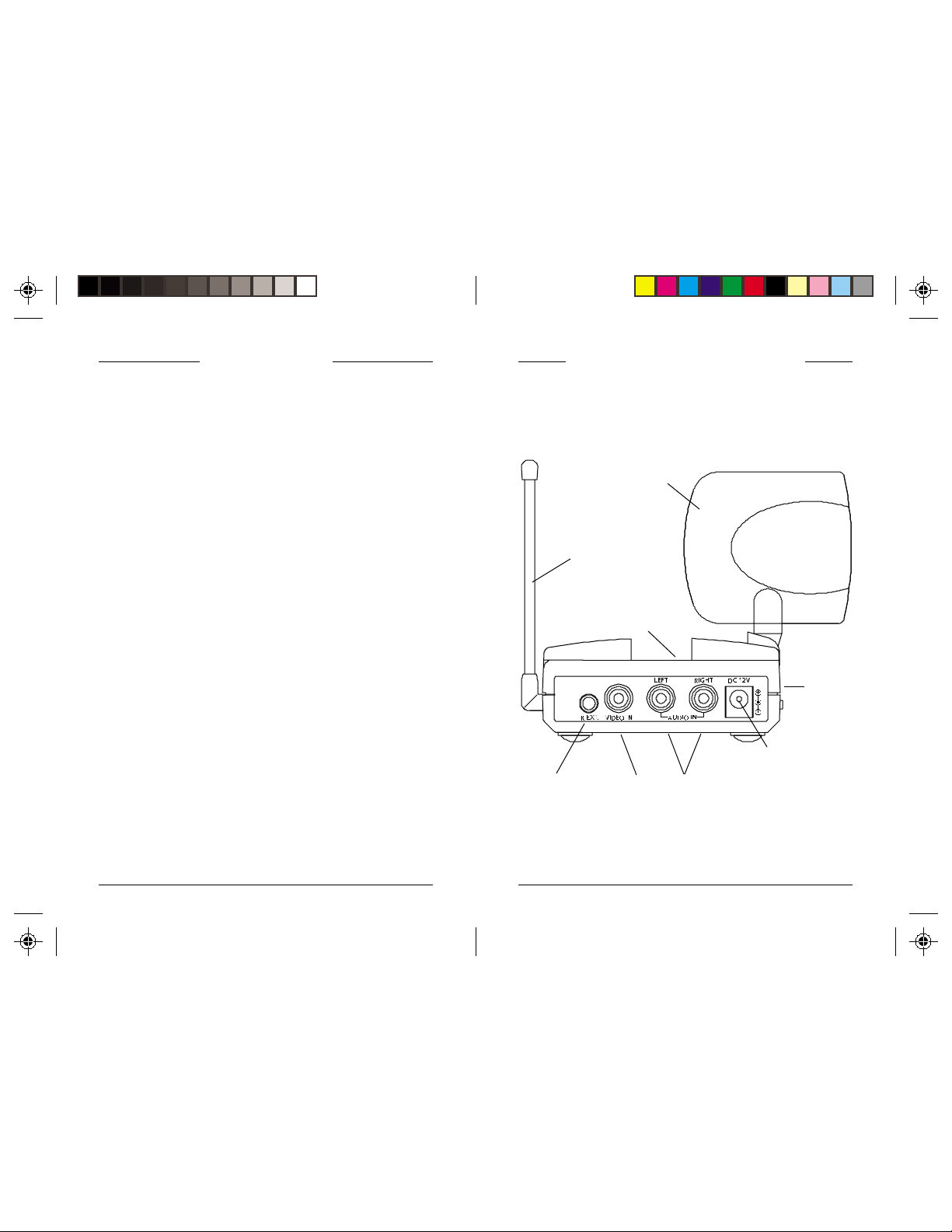
CONTROLS AND CONNECTIONS INTRODUCTION
IR Extender
Jack
2.4 GHz Video
Antenna for
IR Extender
Feature
2.4 GHz Channel
Antenna
Switch
A/V Input
ON-OFF
Switch
(on side)
Power Supply
Jack
Jacks
22
2
22
33
3
33
Page 3

CONNECTING UP
1. Connect one set of Audio/Video cables to the VIDEO and AUDIO
jacks of the Video Sender. Take care to match the colors of the plugs on
the cable with the jacks on the Video Sender.
2. Connect the other end of the cable to the Audio/Video OUT jacks on
your primary TV (the one you want to send the picture FROM). Take
care to match the colors of the plugs on the cable with the jacks on the
TV. If the jacks on the TV are colored differently, connect the yellow
plug to the jack labelled VIDEO, the red plug to the jack labelled
AUDIO RIGHT and the white plug to the jack labeled AUDIO LEFT.
Note: If your TV does not include Audio/Video OUT jacks, you will
need to remake the connections as shown in diagram b) using the
TV antenna (coaxial) connections to link up the DBS Receiver/
Cable Box/VCR to your TV.
A/V Cable Coaxial
a) Connections for a TV
with A/V OUT jacks.
b) Connections for a TV
without A/V OUT
jacks.
Cable
3. Plug the Video Sender's Power Supply (the smaller of the two power
supplies) into a convenient 120 volt wall outlet and plug its jack into the
Video Sender.
4. Position the Video Sender in a convenient location such as on top of the
TV and orient the antenna so that the flat side points in the direction of
the room where you will be installing the Video Receiver.
IF YOU HAVE SEVERAL A/V COMPONENTS
If you have two or more A/V components
(e.g. DBS, VCR, Cable Box, DVD, etc.)
that you want to watch in another room,
they will probably already be hooked up to
the local TV in series (see the diagram to
the right). To connect the Video Sender
you just need to identify the last component
in the chain and connect its LINE OUT
jacks to the Video Sender's A/V jacks.
If the last component in the chain does not
have spare LINE OUT jacks, reconnect
the TV to the last component in the chain
using the included COAX cable to connect
the VHF/UHF ports, then use the A/V
connections for the Video Sender.
Point the small tubular antenna up if you
intend to use the IR Extender feature (See
page 7).
TV
DVD Player
DBS (Satellite )
Receiver
Cable Box
IF YOU WANT TO USE YOUR VIDEO SENDER TO TRANSMIT FROM
STEREO SYSTEM ONLY
YOUR
Just hook up the Video Sender using only the red and white jacks for the
right and left channels of the audio signal. Leave the yellow (video) jack
unconnected.
44
4
44
55
5
55
Page 4

THE REMOTE EXTENDER FEATURE
The Remote Extender feature allows X10 universal remotes to control some
models of RCA DBS Receivers from another room. For example, you can
change channels on your Satellite Receiver while viewing in another room.
To use the Remote Extender Function you need to use the included Remote
Extender Cable. Connect this cable to the IR jack on the Video Sender.
Connect the other end of the cable to the IR Control input on the RCA DBS
Receiver (DBS II or later model).
Point the small tubular antenna on the Video Sender up.
To operate the controls on the RCA DBS Satellite Receiver from another
room, just press the appropriate buttons on the remote (in SAT mode). The
remote sends RF signals directly to the Video Sender, even through walls.
The Video Sender passes these signals through the Remote Extender cable
to the RCA DBS Satellite Receiver.
If you get a picture but the quality is poor:
Try different positions for the antennas on the Sender and Receiver . The system
usually works best with the flat side of the antennas facing each other (see
diagram below). Sometimes, however, reflections and other effects in the home
might affect the signal so that some adjustment of either the Sender or Receiver
antenna may be necessary to get the best the signal.
Point antennas at each other
TROUBLESHOOTING
If you do not see a picture on your TV:
Check that the Sender and the Receiver are on the same letter channel (A, B,
C, or D). The channel switches are on the bottom of the units.
There is a power light on the front of each unit. Check that the power switch
on the side of each unit is ON.
Verify that your connections to the TV are correct. If you are using the RCA
jacks, make sure you are using the appropriate input mode for your TV, try
pressing the A-B button or Video button on your TV's remote control to change
the input mode (consult your TV's owner's manual, if necessary). If you are
using the COAX cable, verify that the Receiver and the TV are on the same
channel (3 or 4).
If you connected the Receiver to a VCR and then connected the VCR to your
TV, you might need to turn the VCR OFF to see the picture on your TV. Or
you might need to turn the VCR on, AND set it to record the picture from the
Video Sender, in order to see the picture on your TV. Or you might need to
press the A-B button on your VCR's remote control. Consult your VCR's
owner's manual from more information.
66
6
66
TRANSMITTER
Take a look at what the video signal is passing through or near to get to the
Receiver. Metal objects and electromagnetic fields can distort the signal. Try
to keep the Receiver as far away from other devices as the cables allow. In
most cases, relocating the Sender or Receiver a few feet is enough to avoid
the source of interference.
Try unplugging/turning off any electromagnetic interference producing devices,
such as a microwave oven, baby monitor, computer, wireless LAN, wireless
speakers, cordless phone, cell phone, etc. Other 2.4 GHz devices can distort
the picture and/or cause buzzing in the audio. If you are experiencing
interference between the Video Sender and some other equipment that uses
2.4 GHz, check the other device's owner's manual for the frequencies of each
channel that it uses. X10 Video Senders use the following frequencies: Channel
A: 2.411 GHz, Chan B: 2.434 GHz, Chan C: 2.453 GHz, Chan D: 2.473 GHz.
We recommend using a frequency on the other device that is farthest from
channel A or D, depending on which side of the band the other device is
transmitting. Otherwise you will need to discontinue use of the device while
using the Video Sender and Receiver.
RECEIVER (SOLD SEPARATELY)
For more help with setup please visit www .x10.com/support
77
7
77
Page 5

12 MONTH LIMITED WARRANTY
X10.COM A DIV . OF X10 WIRELESS TECHNOLOGY, INC. (X10) WARRANTS ITS
PRODUCTS TO BE FREE FROM DEFECTIVE MATERIAL AND WORKMANSHIP
FOR A PERIOD OF ONE (1) YEAR FROM THE ORIGINAL DATE OF PURCHASE
AT RE TAIL. X10 AGREES T O REP AIR OR REPLACE, AT ITS SOLE DISCRETION,
A DEFECTIVE X10 PRODUCT IF RETURNED TO X10 WITHIN THE WARRANTY
PERIOD AND WITH PROOF OF PURCHASE.
IF SERVICE IS REQUIRED UNDER THIS WARRANTY:
1. CALL 1-800-675-3044, OR VISIT WWW.X10.COM, OR E-MAIL
SALES@X10.COM TO OBTAIN A RETURN MERCHANDISE
AUTHORIZA TION (RMA) NUMBER.
2. RETURN THE DEFECTIVE UNIT POSTAGE PREPAID T O THE ADDRESS
BELOW
3. ENCLOSE A CHECK FOR $4.00 TO COVER HANDLING AND RETURN
POST AGE.
4. ENCLOSE A DATED PROOF OF PURCHASE.
5. X10 IS NOT RESPONSIBLE FOR SHIPPING DAMAGE. UNITS TO BE
RETURNED SHOULD BE P ACKED CAREFULL Y.
THIS W ARRANTY DOES NOT EXTEND T O ANY X10 PRODUCTS WHICH
HA VE BEEN SUBJECT TO MISUSE, NEGLECT , ACCIDENT, INCORRECT WIRING
OR TO USE IN VIOLA TION OF OPERA TING INSTRUCTIONS FURNISHED BY
US, NOR EXTEND TO ANY UNITS ALTERED OR REP AIRED FOR WARRANTY
DEFECT BY ANYONE OTHER THAN X10. THIS WARRANTY DOES NOT
COVER ANY INCIDENTAL OR CONSEQUENTIAL DAMAGES AND IS IN LIEU
OF ALL OTHER W ARRANTIES EXPRESSED OR IMPLIED AND NO
REPRESENTA TIVE OR PERSON IS AUTHORIZED TO ASSUME FOR US ANY
OTHER LIABILITY IN CONNECTION WITH THE SALE OF OUR PRODUCTS.
SOME STA TES DO NOT ALLOW LIMITATIONS ON HOW LONG AN IMPLIED
WARRANTY LASTS, AND/OR THE EXCLUSION OR LIMITATION OF
INCIDENTAL OR CONSEQUENTIAL DAMAGES SO THE ABOVE LIMITATIONS
AND EXCLUSIONS MAY NOT APPLY T O THE ORIGINAL CUSTOMER. THIS
WARRANTY GIVES YOU SPECIFIC RIGHTS AND YOU MAY ALSO HA VE
OTHER RIGHTS WHICH VAR Y FROM STATE TO ST A T E.
X10.com, a div. of X10 Wireless Technology, Inc.
Returns Depot, 3824 North 5th St.,
Suite C, North Las Vegas, NV 89032
Web Site: www.x10.com
VT32A-09/01
 Loading...