

Page 1
Additional Audio/Video Receiver
for use with X10 Video Sender
Systems
MODEL VR30A OWNER'S MANUAL
Page 2
INTRODUCTION
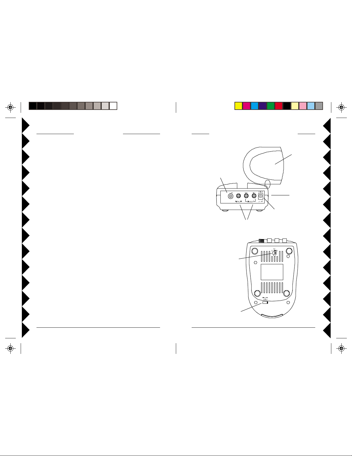
CONTROLS AND CONNECTIONS
The VR30A Video Receiver works with X10's Wireless Video Sender kit
(VK30A) for situations where you want to install an additional receiver on
another TV, for example. The VK30A's Sender base unit connects to your
DBS™ receiver, VCR, Cable Box, etc., and the Receiver unit connects to a
TV in another room. The Video Sender converts the A/V signal from your
DBS receiver, VCR, Cable Box, etc., into a radio signal and transmits it
(even through walls) to the Video Receiver unit. The Video Receiver
converts the signals back to A/V signals which are fed through a cable to
your TV's COAX or A/V input jacks. By purchasing additional VR30As
you can view your DBS receiver VCR, Cable Box, etc., on more than one
TV.
FCC CAUTION
THIS DEVICE COMPLIES WITH PART 15 OF THE FCC RULES.
OPERATION IS SUBJECT TO THE FOLLOWING TWO CONDITIONS:
(1) THIS DEVICE MAY NOT CAUSE HARMFUL INTERFERENCE, AND
(2) THIS DEVICE MUST ACCEPT ANY INTERFERENCE RECEIVED, INCLUDING
INTERFERENCE THAT MAY CAUSE UNDESIRED OPERATION.
This equipment generates and uses radio frequency energy, and if not installed and used
properly, that is, in strict accordance with the manufacturers instructions, it may cause
interference to radio and television reception. It has been type tested and found to comply
with the limits for remote control devices in accordance with the specifications in Sub-Parts
B and C of Part 15 of FCC Rules, which are designed to provide reasonable protection
against such interference in a residential installation. However, there is no guarantee that
interference will not occur in a particular installation. If this equipment does cause
interference to radio or television reception, which can be determined by unplugging the
equipment, try to correct the interference by one or more of the following measures.
• Reorient the antenna of the radio/TV experiencing the interference.
• Relocate the equipment with respect to the radio/TV.
• Move the equipment away from the radio/TV.
• Plug the equipment into an outlet on a different electrical circuit from the radio/TV
experiencing the interference.
• If necessary, consult your local Dealer for additional suggestions.
NOTE: Modifications to this product will void the user's authority to operate this
equipment.
2.4 GHz Video
Antenna
TV Output
Connector
ON-OFF
Switch
(on side)
Power Supply
Jack
A/V Jacks
TV
Channel
Switch
2.4 GHz
Channel
Switch
22
2
22
33
3
33
Page 3

CONNECTING UP
1. Connect a set of Audio/Video cables to
the A/V OUT jacks on the Audio/Video
Receiver. Connect the other end to
your TV (use Yellow for video, and
either L or R channel for audio).
2. Plug the Audio/Video Receiver's Power
Supply jack (the larger power supply
than the one used for the Sender) into
the Audio/Video Receiver and plug the
power supply into a 120 volt wall outlet.
3. Turn the Audio/Video Receiver's power
switch (on side of unit) on.
4. Set the channel switch to the same letter as you set on the Video
Sender, A, B, C, or D.
5. Position the Audio/Video Receiver in a convenient location such as on
top of the TV and orient the antenna so that the flat side points in the
direction where you set up the Video Sender.
IF YOUR TV DOES NOT HAVE A/V CONNECTORS
You can use the supplied coaxial cable to connect the TV OUT socket on
the Audio/Video Receiver to the Antenna input on your TV.
If you already have an
antenna connected to
your TV, you will need to
use a TV antenna
splitter. Set your TV and
the TV Channel switch
on the Audio/Video
Receiver (on bottom) to
the same channel (3 or
4).
IF YOUR TV IS ALREADY HOOKED UP TO A
DBS RECEIVER OR OTHER A/V DEVICE
If a DBS Receiver or other A/V
component is connected to the TV using
A/V cables, you can connect the Audio/
Video Receiver to the free LINE IN jacks
on the component. If there are no LINE
IN jacks, you will need to use a TV
antenna splitter as described earlier.
IF YOU WANT TO USE YOUR VIDEO SENDER TO TRANSMIT FROM YOUR STEREO
SYSTEM ONLY
Just hook up the Video Sender using only the red and white jacks for the
right and left channels of the audio signal. Leave the yellow (video) jack and
COAX cable unconnected.
44
4
44
55
5
55
Page 4

TROUBLESHOOTING
If you do not see a picture on your TV:
Check that the Sender and the Receiver are on the same letter channel (A, B,
C, or D). The channel switches are on the bottom of the units.
There is a power light on the front of each unit. Check that the power switch
on the side of each unit is ON.
Verify that your connections to the TV are correct. If you are using the RCA
jacks, make sure you are using the appropriate input mode for your TV, try
pressing the A-B button or Video button on your TV's remote control to change
the input mode (consult your TV's owner's manual, if necessary). If you are
using the Coax cable, verify that the Receiver and the TV are on the same
channel (3 or 4).
If you connected the Receiver to a VCR and then connected the VCR to your
TV, you might need to turn the VCR OFF to see the picture on your TV. Or
you might need to turn the VCR on, AND set it to record the picture from the
Video Sender, in order to see the picture on your TV. Or you might need to
press the A-B button on your VCR's remote control. Consult your VCR's
owner's manual from more information.
If you get a picture but the quality is poor:
Try different positions for the antennas on the Sender and Receiver. The system
usually works best with the flat side of the antennas facing each other (see
diagram below). Sometimes, however, reflections and other effects in the home
may affect the signal so that some adjustment of either the Sender or Receiver
antenna may be necessary to get the best the signal.
Point antennas at each other
Take a look at what the video signal is passing through or near to get to the
Receiver. Metal objects and electromagnetic fields can distort the signal. Try
to keep the Receiver as far away from other devices as the cables allow.
In most cases, relocating the Sender or Receiver a few feet is enough to avoid
the source of interference.
Try unplugging/turning off any electromagnetic interference producing devices,
such as a microwave oven, baby monitor, computer, wireless LAN, wireless
speakers, cordless phone, cell phone, etc.
Other 2.4 GHz devices can distort the picture and/or cause buzzing in the
audio. If you are experiencing interference between the Video Sender and
some other equipment that uses 2.4 GHz, check the other device's owner's
manual for the frequencies of each channel that it uses. X10 Video Senders
use the following frequencies: Channel A: 2.411 GHz, Chan B: 2.434 GHz,
Chan C: 2.453 GHz, Chan D: 2.473 GHz. We recommend using a frequency
on the other device that is farthest from channel A or D, depending on which
side of the band the other device is transmitting. Otherwise you will need to
discontinue use of the device while using the Video Sender and Receiver.
For more help with setup please visit www .x10.com/support
VIDEO TRANSMITTER
(SOLD SEPARATELY)
VIDEO RECEIVER
66
6
66
77
7
77
Page 5

12 MONTH LIMITED WARRANTY
X10.COM A DIV . OF X10 WIRELESS TECHNOLOGY, INC. (X10) W ARRANTS ITS
PRODUCTS TO BE FREE FROM DEFECTIVE MATERIAL AND WORKMANSHIP
FOR A PERIOD OF ONE (1) YEAR FROM THE ORIGINAL DATE OF PURCHASE
AT RE TAIL. X10 AGREES T O REP AIR OR REPLACE, AT ITS SOLE DISCRETION,
A DEFECTIVE X10 PRODUCT IF RETURNED TO X10 WITHIN THE WARRANTY
PERIOD AND WITH PROOF OF PURCHASE.
IF SERVICE IS REQUIRED UNDER THIS WARRANTY:
1. CALL 1-800-675-3044, OR VISIT WWW .X10.COM, OR E-MAIL
SALES@X10.COM TO OBTAIN A RETURN MERCHANDISE
AUTHORIZA TION (RMA) NUMBER.
2. RETURN THE DEFECTIVE UNIT POSTAGE PREPAID T O THE ADDRESS
BELOW
3. ENCLOSE A CHECK FOR $4.00 TO COVER HANDLING AND RETURN
POST AGE.
4. ENCLOSE A DA TED PROOF OF PURCHASE.
5. X10 IS NOT RESPONSIBLE FOR SHIPPING DAMAGE. UNITS TO BE
RETURNED SHOULD BE P ACKED CAREFULLY.
THIS W ARRANTY DOES NOT EXTEND T O ANY X10 PRODUCTS WHICH
HA VE BEEN SUBJECT TO MISUSE, NEGLECT , ACCIDENT , INCORRECT WIRING
OR TO USE IN VIOLA TION OF OPERA TING INSTRUCTIONS FURNISHED BY
US, NOR EXTEND TO ANY UNITS ALTERED OR REPAIRED FOR WARRANTY
DEFECT BY ANYONE OTHER THAN X10. THIS WARRANTY DOES NOT
COVER ANY INCIDENTAL OR CONSEQUENTIAL DAMAGES AND IS IN LIEU
OF ALL OTHER W ARRANTIES EXPRESSED OR IMPLIED AND NO
REPRESENTATIVE OR PERSON IS AUTHORIZED TO ASSUME FOR US ANY
OTHER LIABILITY IN CONNECTION WITH THE SALE OF OUR PRODUCTS.
SOME STATES DO NOT ALLOW LIMITA TIONS ON HOW LONG AN IMPLIED
W ARRANTY LASTS, AND/OR THE EXCLUSION OR LIMIT ATION OF
INCIDENTAL OR CONSEQUENTIAL DAMAGES SO THE ABOVE LIMITATIONS
AND EXCLUSIONS MAY NOT APPLY T O THE ORIGINAL CUST OMER. THIS
W ARRANTY GIVES YOU SPECIFIC RIGHTS AND YOU MA Y ALSO HAVE
OTHER RIGHTS WHICH V A RY FROM ST A T E T O ST A TE.
X10.com, a div. of X10 Wireless Technology, Inc.
Returns Depot, 3824 North 5th St.,
Suite C, North Las Vegas, NV 89032
Web Site: www.x10.com
VR30A-09/01
 Loading...