

Page 1
OWNER'S MANUAL
XM14A
OWER SUPPLY
P
C2
C1
CAMERA
C4
C3
P2
P1
POSITION
P3
P4
SweepCenter
SCAN
A
.
.
C
O
.
.
E
M
.
.
Normal
GIK
..
Program
CAMERA (SOLD
SEP ARATELY
)
CR14A
EMOTE
R
ZC15A
P
AN 'N
TILT BASE
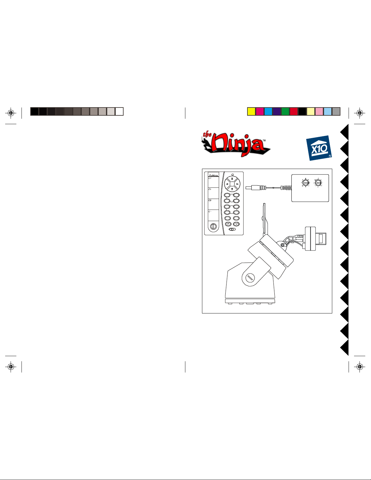
MODEL VK74A PAN 'N TILT CAMERA SYSTEM
INCLUDES ZC15A PAN 'N TILT BASE, XM14A ADDRESSABLE
SUPPLY, CR14A REMOTE (CAMERA SOLD SEPARATELY)
POWER
Page 2
INTRODUCTION
CONTENTS
The VK74A includes the ZC15A Pan ‘n Tilt Camera Base with XM14A
remote controlled power supply, and the CR14A remote control. You attach
any XCam2 wireless camera (XX11A or XX13A) or any XCam 2 Instant
On Camera (XX16A or XX17A) to the Pan ‘n Tilt Camera Base and then
you can remotely control the camera’s position using a CR14A remote
control. The camera sends the picture and sound to a Receiver that you
connect to your TV, up to 100 ft. away. (Cameras and Receivers sold
separately).
FCC CAUTION
THIS DEVICE COMPLIES WITH PAR T 15 OF THE FCC RULES.
OPERA TION IS SUBJECT TO THE FOLLOWING TWO CONDITIONS:
(1)THIS DEVICE MAY NOT CAUSE HARMFUL INTERFERENCE, AND
(2)THIS DEVICE MUST ACCEPT ANY INTERFERENCE RECEIVED, INCLUDING
INTERFERENCE THA T MA Y CAUSE UNDESIRED OPERA TION.
This equipment generates and uses radio frequency energy, and if not installed and
used properly, that is, in strict accordance with the manufacturers instructions, it
may cause interference to radio and television reception. It has been type tested
and found to comply with the limits for remote control devices in accordance with
the specifications in Sub-Parts B and C of Part 15 of FCC Rules, which are designed
to provide reasonable protection against such interference in a residential
installation. However, there is no guarantee that interference will not occur in a
particular installation. If this equipment does cause interference to radio or
television reception, which can be determined by unplugging the equipment, try to
correct the interference by one or more of the following measures.
• Reorient the antenna of the radio/TV experiencing the interference.
• Relocate the equipment with respect to the radio/TV.
• Move the equipment away from the radio/TV .
• Plug the equipment into an outlet on a different electrical circuit from the radio/TV
experiencing the interference.
• If necessary, consult your local Dealer for additional suggestions.
NOTE: Modifications to this product will void the user's authority to operate this
equipment.
CONTROLS AND CONNECTIONS ...............................................................4
P
AN 'N TILT BASE WITH CAMERA AND POWER SUPPLY ............................4
R
ECEIVER .........................................................................................5
Q
UICK SET UP .....................................................................................6
C
ONNECTING UP ..................................................................................7
C
ONNECTING UP THE PAN 'N TILT BASE AND INSTANT-ON CAMERAS .........7
C
ONNECTING UP THE PAN 'N TILT BASE AND XCAM2 CAMERAS ...............8
C
ONNECTING UP THE RECEIVER ......................................................... 11
R
EMOTE CONTROL ..............................................................................12
S
INGLE CAMERA OPERATION................................................................13
S
TORING SWEEP POSITIONS ..............................................................13
C
LEARING ALL STORED POSITIONS ....................................................13
C
ENTERING .................................................................................... 13
S
WEEPING ...................................................................................... 13
S
TOPPING A SWEEP .......................................................................... 13
T
URNING THE CAMERA OFF ............................................................. 13
M
ULTI-CAMERA SYSTEMS .................................................................... 14
I
NSTALLING A TRANSCEIVER ............................................................... 14
T
URNING CAMERAS ON AND OFF ........................................................ 14
S
TORING SWEEP POSITIONS ..............................................................15
C
LEARING ALL STORED POSITIONS ....................................................15
C
ENTERING .................................................................................... 15
S
WEEPING ...................................................................................... 16
S
TOPPING A SWEEP .......................................................................... 16
T
O CHANGE THE CODES THAT C1 THRU C4 CONTROL ........................... 16
T
ROUBLESHOOTING ............................................................................. 16
22
2
22
33
3
33
Page 3
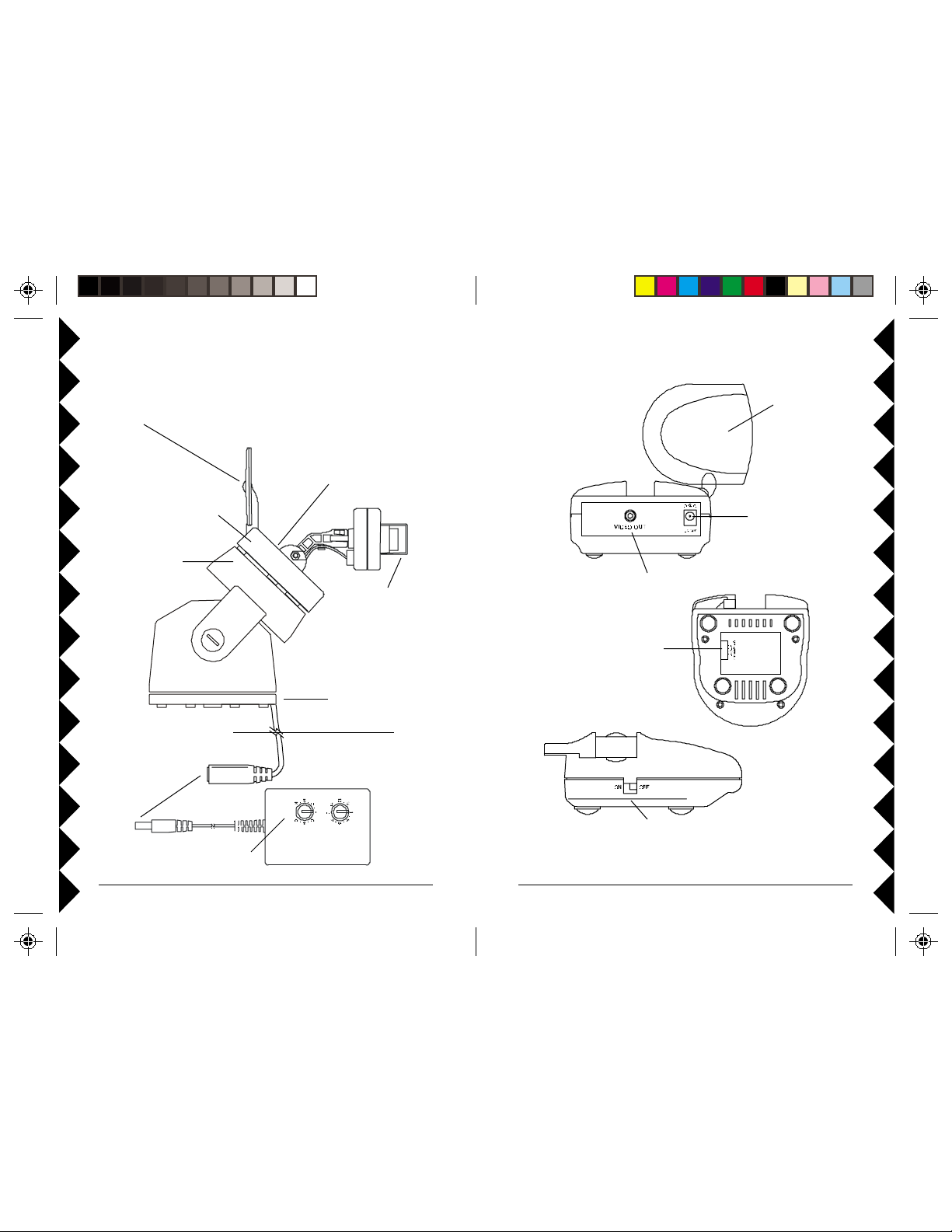
CONTROLS AND CONNECTIONS
Point the raised dimple on the
antenna towards the Receiver’s
location.
Camera
(sold separately).
ZC15A Pan 'n
Tilt Base.
Plug power
supply in
here.
Set channel switch (under
rubber plug) to match setting on
VR31A or VR36A Receiver.
(A is at bottom, D is at top).
It is factory set to A.
Remove clear cap and
turn lens counterclockwise
to focus (replace cap for
outdoor use).
Attach to a wall using
mounting bracket
(supplied).
Outdoors
Indoors
VR36A VIDEO RECEIVER (SOLD SEPARATEL Y)
2.4 GHz Video
Antenna
Power Supply
Jack
Video Out Jack
2.4 GHz
Channel Switch
Set the code used to
turn on and off from
X10 remote controls.
ON-OFF Switch
XM14A
44
4
44
55
5
55
Page 4
FRO NT
FRONT
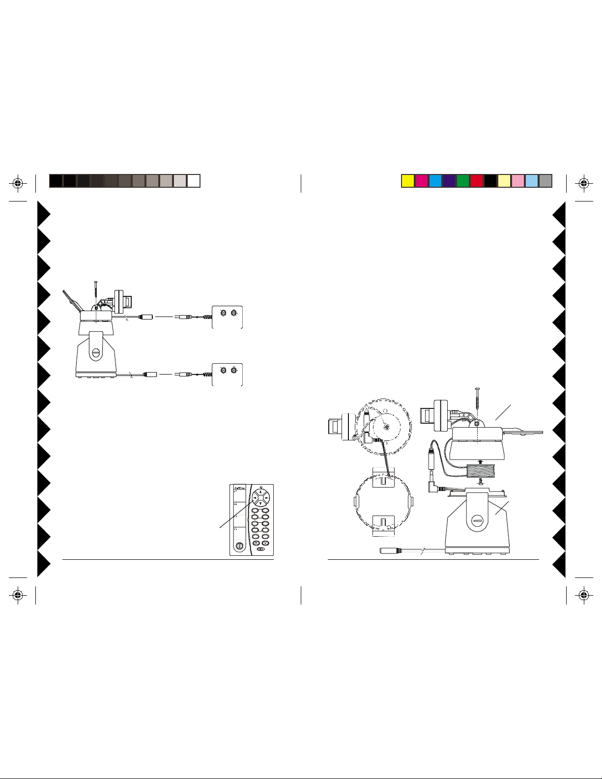
QUICK SETUP
CONNECTING UP
Before you continue it is recommended that you follow the steps below to
give the system a quick try. Later (pages 7 and 8) you can see how to
connect the camera’s cord inside the top of the Ninja so you only need one
power supply.
Attach camera to top of
!
Ninja with screws provided.
XM10A or
XM13A*
Plug camera into power supply
#
included with it, and plug power
supply into an AC outlet.
XM14A*
* IMPORTA NT! Do not interchange
power supplies. Model XM14A must be
used only for the Ninja Pan ‘n Tilt base.
Plug Ninja into power supply
"
included with it, and plug power
supply into an AC outlet.
Now connect the Receiver to your TV (see page 11).
● Point the “pip” on the Camera’s antenna and the “squares” on the
Receiver’s antenna towards each other for the best reception.
● If you experience interference, try setting the Camera and Receiver to a
different letter channel (A, B, C, or D) - use the same letter on each.
Now try it out!
● Insert 4 AAA alkaline batteries (not included) in the
Remote Control.
● Press the blue buttons at the top of the remote to pan
the camera left and right, and tilt it up and down.
C1
CAMERA
C3
P1
PO SITI O N
P3
SCA N
A
.
.
C
O
.
.
E
M
.
.
Normal
GIK
..
For Instant-On cameras, models XX16A and XX17A (sold separately):
1. Remove the top from the Pan ‘n Tilt base, position the camera with its
cable at the front of the top housing (where the notch for the cable is)
and attach the camera to the housing using the screws provided.
2. Remove the spindle attached on the inside of the top housing, neatly coil
the camera wire into the spindle.
3. Put the coiled spindle back into the top housing and use the supplied
washer head screw to attach it in the housing.
4. Plug the power jack from camera into the jack on the Pan ‘n Tilt base,
and put the jacks into the top housing. (Only Instant-On cameras fit,
adapter required for non Instant-On cameras, see next page).
5. Attach the top housing to the Pan ‘n Tilt base, make sure the front of the
housing goes to the front of the Pan ‘n Tilt base.
XCam2 Instant
On camera, (sold
separately)
ZC15A
Pan 'n Tilt
C2
C4
P2
P4
SweepCenter
Pro gra m
Base
66
6
66
77
7
77
Page 5

For XCam 2 cameras, models XX1 1A and XX13A (sold separately):
1. Remove the top from the Pan ‘n Tilt base, position the camera with its
cable at the front of the top housing (where the notch for the cable is)
and attach the camera to the housing using the screws provided.
2. Remove the spindle attached on the inside of the top housing, neatly coil
the camera wire into the spindle.
3. Put the coiled spindle back into the top housing and use the supplied
washer head screw to attach it in the housing.
4. Plug the power jack from camera and jack on the pan ‘n tilt base into the
supplied adapter, and put the jacks into the top housing. Use the adapter
only for non Instant-On cameras (models XX11A and XX13A).
5. Attach the top housing to the Pan ‘n Tilt base, make sure the front of the
housing goes to the front of the Pan ‘n Tilt base.
XCam2 camera,
(sold separately)
FRONT
Adapter for non
Instant-On cameras
FRONT
Adapter for non
Instant-On cameras
ZC15A
Pan 'n Tilt
Base
6. Attach the Pan 'n Tilt base to the mounting bracket.
7. Install the complete assembly in a suitable location. If you install it
outdoors, run the jack through a hole in the wall, or through a window, so
you can plug the power supply into an AC outlet indoors.
Indoors
Outdoors
Pan 'n Tilt
Base
Mounting
Bracket
8. Plug the power supply’s jack into the cable on the
Pan 'n Tilt Base.
9. Plug the power supply into any 120V AC outlet.
10.Set the Housecode dial to a letter between A and P
that matches the Housecode dial on the X10 remote
controls you want to use it with. Set the Unit Code
dial to a number between 1 and 4. This lets you turn
the camera connected to the XM14A on and off by
remote control, using the CR14A remote.
(Transceiver required).
XM14A
88
8
88
99
9
99
Page 6

11.Set the channel switch on the camera to the same setting as the one on
the VR31A or VR36A Video Receiver (A, B, C, or D).
12.Adjust the antenna if necessary to aim it in the direction of the TV that
you will view the camera on.
Point antennas
at each other.
Outdoors Indoors
Set up additional cameras if you have them (up to 4). Set each camera to
the same channel as the Receiver (A, B, C, or D). Set each power supply
to a different number within one of the groups (1-4, 5-8, 9-12, or 13-16).
Receiver (sold
separately)
connected to
your TV .
RECEIVER
HOOKING UP THE VR36A VIDEO RECEIVER
(SOLD SEPARATELY)
1. Connect a Video cable to the VIDEO
OUT jack on the Video Receiver.
Connect the other end to your TV's
VIDEO IN jack. If your TV does not
have a Video IN jack, you will need to
purchase an RF modulator, or connect
as shown in the diagram below.
2. Plug the Video Receiver's Power
Supply jack (the power supply with NO
code wheels) into the Video Receiver
and plug the power supply into a 120 volt wall outlet.
3. Turn the Video Receiver's power switch (on side of unit) on.
4. Set the channel switch to the same letter as you set on the Camera, A,
B, C, or D.
5. Position the Video Receiver in a convenient location such as on top of
the TV and orient the antenna so that the flat side points in the direction
of the room where you set up the Camera.
Point antenna towards
the Receiver
Outdoors Indoors
1010
10
1010
IF YOUR TV IS ALREADY HOOKED UP TO A
DBS RECEIVER OR OTHER A/V DEVICE, OR
YOUR TV DOES NOT HAVE A VIDEO IN
IF
JACK
If a DBS Receiver or other A/V
component is connected to the TV using
A/V cables, you can connect the Video
Receiver to the free LINE IN jacks on the
component.
1111
11
1111
Page 7

REMOTE CONTROL
The Remote lets you move the camera from left to right (Pan) and up and
down (Tilt). You can store 4 positions for the camera and use the remote to
"Sweep" between these positions.
Install 4 AAA alkaline batteries (sold separately) in the remote’s battery
compartment.
Write locations of
cameras here.
C1
CAME RA
C3
P1
Centers the
camera.
Set to the same letter as
the Transceiver and
camera power supplies.
A
.
.
C
O
.
.
E
M
.
.
GIK
..
POSITI ON
P3
SCAN
Normal
Scans forward or backward thru
cameras controlled by C1 thru C4.
Hold to step every 6 seconds.
If you purchase multiple Pan 'n Tilt Cameras, and purchase a Transceiver
(RR501 or TM751) the Remote lets you turn on any of 4 cameras or scan
each of them in turn (forward or backward) so as to display the image from
each camera in turn on your TV. You connect each camera (up to 4) to its
own Pan 'n Tilt Base, plug each one into an Addressable Power Supply, an d
set each to a different number between 1-4, 5-8, 9-12, or 13-16
Swe epCent er
C2
C4
P2
P4
Program
“Tilts” up and down.
“Pans” left and right.
Pressing any of
these turns on that
camera, and turns
the other 3 off
(Transceiver
required). Not used if
you only have one
camera.
Stores 4 positions
for each camera.
Sweeps thru the 4
stored positions for
the selected camera.
SINGLE CAMERA OPERATION
Press a left or right BLUE button at the top of the CR14A Remote to
“Pan” the camera left or right. Press a BLUE up or down button to “Tilt”
the camera up or down.
Buttons P1 thru P4 are used to store 4 position settings for the
camera.
1. To store the first position for the camera, press the BLUE buttons to
scan to the position you want. Move the switch at the bottom from
Normal to Program. Press P1.
2. To store the second position for the camera, press the BLUE buttons to
scan to the position you want. Move the switch at the bottom from
Normal to Program. Press P2.
3. To store the third position for the camera, press the BLUE buttons to
scan to the position you want. Move the switch at the bottom from
Normal to Program. Press P3.
4. To store the fourth position for the camera, press the BLUE buttons to
scan to the position you want. Move the switch at the bottom from
Normal to Program. Press P4. Move the switch back to Normal.
To clear all stored positions:
Move the switch at the bottom to Program. Press Center then move the
switch back to Normal.
WITH THE SWITCH SET TO NORMAL:
Press P1, P2, P3 or P4 to move to any of the 4 positions stored for the
camera.
Press Center to center the position for the camera.
Press Sweep to sweep through all 4 positions stored for the camera.
To stop scanning or movement to a stored position:
Press any BLUE key on the remote while the camera is moving to stop the
movement.
To turn the camera off:
Unplug its power supply. For multiple camera systems a Transceiver is
required, which then lets you turn the cameras on and off by remote control.
1212
12
1212
1313
13
1313
Page 8

MULTI-CAMERA SYSTEMS
STOP! If you only own one Pan 'n Tilt Camera, you don't need to
read any further.
Important: For a Multi Camera system you will need to install a
Transceiver (Model RR501 OR TM751, each sold separately). Set its
Housecode to match the CR14A Remote, and XM14A power supplies
you've installed.
1. Set Housecode to
match the CR14A
Remote, and power
supplies.
1. To control up to 4 Cameras, plug each one into its own Addressable
Power Supply, and set each power supply to the same Housecode you
set on the Transceiver and the Remote. Set each power supply to a
unique number between 1 and 4. Pressing any Camera button (C1, C2,
C3, or C4) turns on that camera (1, 2, 3, or 4) and turns the others (in the
group) off. Then, each press of either the
next or previous camera in the group of 4 while turning the current
camera off. You must set all cameras to the same channel as the Video
Receiver VR31A, or VR36A (Channel A, B, C, D).
2. To “Pan” or “Tilt” a camera: Press C1, C2, C3, or C4 to turn on the
camera. Then press a left or right BLUE button at the top to “Pan” the
camera left or right. Press a BLUE up or down button to “Tilt” the
camera up or down.
2. Plug the Transceiver
into an AC outlet
located centrally in
your home.
or button turns on the
Buttons P1 thru P4 are used to store 4 position settings for each of
the 4 cameras controlled by buttons C1 thru C4.
1. Press C1.
2. Move the switch at the bottom from Normal to Program.
3. To store the first position for the camera controlled by C1. Press the
BLUE buttons to scan to the position you want. Press P1.
4. To store the second position for the camera controlled by C1. Press the
BLUE buttons to scan to the position you want. Press P2.
5. To store the third position for the camera controlled by C1. Press the
BLUE buttons to scan to the position you want. Press P3.
6. To store the fourth position for the camera controlled by C1. Press the
BLUE buttons to scan to the position you want. Press P4.
7. Move the switch back to Normal.
Press C2 and repeat steps 2 to 7 above to store 4 positions for Camera C2.
Press C3 and repeat steps 2 to 7 above to store 4 positions for Camera C3.
Press C4 and repeat steps 2 to 7 above to store 4 positions for Camera C4.
To clear all stored positions:
Move the switch at the bottom to Program. Press Center then move the
switch back to Normal.
WITH THE SWITCH SET TO NORMAL:
Press C1, then P1, P2, P3 or P4 to move to camera 1's 4 stored positions.
Press C2, then P1, P2, P3 or P4 to move to camera 2's 4 stored positions.
Press C3, then P1, P2, P3 or P4 to move to camera 3's 4 stored positions.
Press C4, then P1, P2, P3 or P4 to move to camera 4's 4 stored positions.
Press C1 then Center to center the position for camera 1.
Press C2 then Center to center the position for camera 2.
Press C3 then Center to center the position for camera 3.
Press C4 then Center to center the position for camera 4.
1414
14
1414
1515
15
1515
Page 9

Press C1 then Sweep to sweep through camera 1's 4 stored positions.
Press C2 then Sweep to sweep through camera 2's 4 stored positions.
Press C3 then Sweep to sweep through camera 3's 4 stored positions.
Press C4 then Sweep to sweep through camera 4's 4 stored positions.
To stop a sweep:
If you press C2, C3, or C4 while camera C1 is sweeping, it will continue to
sweep. To stop Camera C1, press C1, then press any BLUE key.
To Change which group of 4 cameras you want buttons C1, C2, C3,
and C4 to control:
1. To make buttons C1 thru C4 control cameras 5-8 (instead of 1 thru 4)
move the switch at the bottom from Normal to Program, press C2 then
move the switch back to Normal.
2. To make buttons C1 thru C4 control cameras 9-12 move the switch from
Normal to Program, press C3 then move the switch back to Normal.
3. To make buttons C1 thru C4 control cameras 13-16 move the switch
from Normal to Program, press C4 then move the switch back to
Normal.
Note: pressing C1, C2, C3, or C4, turns on that camera and turns the others
in the group off. So you will always have one camera on. The only way to
turn ALL the cameras off is to unplug their power supplies.
TROUBLESHOOTING
If you do not see a picture on your TV:
Check that the Receiver and the Camera are on the same letter channel (A,
B, C, or D). The channel switch on the Camera is located under the rubber
plug on the base of the unit. Make sure you replace the plug afterwards if you
intend to use the camera outdoors.
There is a power light on the front of the Receiver. Check that the power
switch on the side of the Receiver is ON.
Check that the Camera's remote controlled power supply is turned on (using
the CR14A remote control). Note, when you first plug the power supply in, it
will normally be ON.
Verify that your connections to the TV are correct. If you are using the RCA
jacks, make sure you are using the appropriate input mode for your TV, try
pressing the A-B button or Video button on your TV's remote control to change
the input mode (consult your TV's owner's manual, if necessary). If you are
using the Coax cable (VR31A receiver only), verify that the Receiver and the
TV are on the same channel (3 or 4).
If you connected the Receiver to a VCR and then connected the VCR to your
TV , you might need to turn the VCR OFF to see the Camera's picture on your
TV. Or you might need to turn the VCR on, AND set it to record the picture
from the Camera, in order to see the picture on your TV . Or you might need to
press the A-B button on your VCR's remote control. Consult your VCR's
owner's manual from more information.
If you get a picture but the quality is poor:
Try dif ferent positions for the antennas on the Camera and Receiver . Normally
they should point at each other. Sometimes, due to reflections, you might get a
better picture with the Receiver's antenna pointing to the ceiling.
Take a look at what the video signal is passing through or near to get to the
Receiver. Metal objects and electromagnetic fields can distort the signal. Try
to keep the Receiver as far away from other devices as the RCA or Coax
cables allow. In most cases, relocating the Camera or Receiver a few feet is
enough to avoid the source of interference.
Try unplugging/turning off any electromagnetic interference producing devices,
such as a microwave oven, baby monitor, computer, wireless LAN, wireless
speakers, cordless phone, cell phone, etc.
Other 2.4 GHz devices can distort the Camera's picture and/or cause buzzing
in the audio. If you are experiencing interference between X10 Cameras and
some other equipment that uses 2.4 GHz, check the other device's owner's
manual for the frequencies of each channel that it uses. X10 cameras use the
following frequencies: Channel A: 2.411 GHz, Chan B: 2.434 GHz, Chan C:
2.453 GHz, Chan D: 2.473 GHz. We recommend using a frequency on the
other device that is farthest from channel A or D, depending on which side of
the band the other device is transmitting. Otherwise you will need to discontinue
use of the device while using our Cameras.
1616
16
1616
1717
17
1717
Page 10

If the CR14A Pan 'n Tilt Remote doesn't do anything.
Check that the red light on the remote comes on when you press any button.
Check that you have the batteries installed correctly, replace if necessary with
4 AAA alkaline batteries.
Check that you have turned the Camera on. For single camera systems the
power supply for the Camera will normally be on (it powers up on). For MultiCamera systems you need to purchase a TM751 Transceiver for the remote
to be able to turn the Cameras on. When you turn on any one, in a group of 4,
the others in the group turn off. Groups must be 1-4, 5-8, 9-12, or 13-16.
Check that all units are set to the same Housecode.
If you are having difficulty turning the Camera on/off remotely:
Plug the Transceiver (the white module with an antenna) into a different outlet.
Note a Transceiver (sold separately) is REQUIRED for Multi-Camera systems.
If you only have one camera, and don't own a Transceiver, you must unplug
the camera's power supply to turn it off.
If the camera is out of focus:
The camera is shipped preset to be in focus for normal use, but if you want to
change the focus you can remove the clear plastic cover and rotate the inner
portion of the lens. It might be a bit tight. Try turning it counterclockwise first.
If you turn it clockwise do not force or over tighten it. Replace the clear
plastic cover to keep the rain out.
If cameras are sweeping around their programmed positions fast:
Pressing Sweep within 3 seconds of plugging in the camera's power supply
enters fast sweep test mode. Turn the camera off to exit the test mode.
If the camera gradually drifts off the positions you have programmed:
This can happen if the positions you programmed do not cause the camera to
pass through center. If you notice the positions that you programmed for sweep
starting to drift out of position after a while, just press the Center button on the
remote to reset the positions to where you programmed them. Or you can
make the camera periodically center automatically as follows:
Within 3 seconds after you plug the camera's power supply in, press P1, P2,
P3, or P4 on the remote.
Pressing P1 within 3 seconds after you power up forces the camera to recenter every 32 sweeps through the positions you have programmed.
Pressing P2 within 3 seconds after you power up forces the camera to recenter every 64 sweeps through the positions you have programmed.
Pressing P3 within 3 seconds after you power up forces the camera to recenter every 128 sweeps through the positions you have programmed.
Pressing P4 within 3 seconds after you power up forces the camera to recenter every 256 sweeps through the positions you have programmed.
To cancel the above automatic centering:
While the camera is recentering, move the switch on the CR14A remote to
Program, press Sweep, and then move the switch back to Normal.
To stop the camera from ever recentering automatically:
Unplug the camera's power supply, plug it back in, and (within 3 seconds)
press Center. If the camera was sweeping when you unplugged it, it will continue
to sweep when you plug it back in, so you should press any blue key to stop the
sweep before you unplug the Camera.
If the image quality changes as the Ninja base rotates:
Since the Ninja rotates the camera, some positions may move the camera’s
antenna away from the direction of the Video Receiver.
T o improve reception:
· Adjust the antenna on the Video Receiver so that the receiving side (the
one with the 4 squares on it) points towards the camera.
· Move the camera closer to the Video Receiver.
· Move the Video Receiver as far away from other electronic devices as
possible. This can be achieved by using longer audio/video cables
between the Video Receiver and TV, VCR, PC, etc.
· Change the frequency by using the A,B,C,D Channel selector switch on
the camera and receiver. Make sure both match.
· Unplug other wireless equipment such as wireless intercoms, 2.4 GHz
wireless network connections, and 2.4 GHz wireless phones, that could
interfere with the signal from the camera.
For more help with setup please visit www.x10.com/support
1818
18
1818
1919
19
1919
Page 11

12 MONTH LIMITED WARRANTY
X10.COM A DIV . OF X10 WIRELESS TECHNOLOGY, INC. (X10) WARRANTS ITS
PRODUCTS TO BE FREE FROM DEFECTIVE MATERIAL AND WORKMANSHIP
FOR A PERIOD OF ONE (1) YEAR FROM THE ORIGINAL DATE OF PURCHASE
AT RE TAIL. X10 AGREES T O REP AIR OR REPLACE, AT ITS SOLE DISCRETION,
A DEFECTIVE X10 PRODUCT IF RETURNED TO X10 WITHIN THE WARRANTY
PERIOD AND WITH PROOF OF PURCHASE.
IF SERVICE IS REQUIRED UNDER THIS WARRANTY:
1. CALL 1-800-675-3044, OR VISIT WWW.X10.COM, OR E-MAIL
SALES@X10.COM TO OBTAIN A RETURN MERCHANDISE
AUTHORIZA TION (RMA) NUMBER.
2. RETURN THE DEFECTIVE UNIT POST AGE PREPAID TO THE ADDRESS
BELOW.
3. ENCLOSE A CHECK FOR $4.00 TO COVER HANDLING AND RETURN
POST AGE.
4. ENCLOSE A DATED PROOF OF PURCHASE.
5. X10 IS NOT RESPONSIBLE FOR SHIPPING DAMAGE. UNITS TO BE
RETURNED SHOULD BE P ACKED CAREFULL Y.
THIS W ARRANTY DOES NOT EXTEND T O ANY X10 PRODUCTS WHICH
HA VE BEEN SUBJECT TO MISUSE, NEGLECT , ACCIDENT, INCORRECT WIRING
OR TO USE IN VIOLA TION OF OPERA TING INSTRUCTIONS FURNISHED BY
US, NOR EXTEND TO ANY UNITS ALTERED OR REP AIRED FOR WARRANTY
DEFECT BY ANYONE OTHER THAN X10. THIS WARRANTY DOES NOT
COVER ANY INCIDENTAL OR CONSEQUENTIAL DAMAGES AND IS IN LIEU
OF ALL OTHER W ARRANTIES EXPRESSED OR IMPLIED AND NO
REPRESENTA TIVE OR PERSON IS AUTHORIZED TO ASSUME FOR US ANY
OTHER LIABILITY IN CONNECTION WITH THE SALE OF OUR PRODUCTS.
SOME STA TES DO NOT ALLOW LIMITATIONS ON HOW LONG AN IMPLIED
WARRANTY LASTS, AND/OR THE EXCLUSION OR LIMITATION OF
INCIDENTAL OR CONSEQUENTIAL DAMAGES SO THE ABOVE LIMITATIONS
AND EXCLUSIONS MAY NOT APPLY T O THE ORIGINAL CUSTOMER. THIS
WARRANTY GIVES YOU SPECIFIC RIGHTS AND YOU MAY ALSO HA VE
OTHER RIGHTS WHICH VAR Y FROM STATE TO STATE.
X10.com, a division of X10 Wireless Technology, Inc.
(Returns Depot), 3824 North 5th St., Suite C,
North Las Vegas, NV 89032
Web Site: www.x10.com/support
VK74A-01/02
 Loading...