

Page 1
SoundPSoundP
SoundP
SoundPSoundP
oo
o
oo
ww
er er
w
er
ww
er er
™
WW
W
WW
irir
elesseless
ir
eless
irir
elesseless
SpeakSpeak
Speak
SpeakSpeak
er Drier Dri
er Dri
er Drier Dri
vv
er Systemer System
v
er System
vv
er Systemer System
OWNER'S MANUALOWNER'S MANUAL
OWNER'S MANUAL
OWNER'S MANUALOWNER'S MANUAL
MM
M
MM
((
INCLUDESINCLUDES
INCLUDES
(
INCLUDESINCLUDES
((
UR78A RUR78A R
UR78A R
UR78A RUR78A R
ODELODEL
ODEL
ODELODEL
VK59A VK59A
VK59A
VK59A VK59A
VT35A S VT35A S
VT35A S
VT35A S VT35A S
EMOTEEMOTE
EMOTE
EMOTEEMOTE
))
)
))
ENDERENDER
ENDER
ENDERENDER
, VR32A R, VR32A R
, VR32A R
, VR32A R, VR32A R
ECEIVERECEIVER
ECEIVER
ECEIVERECEIVER
, ,
,
, ,
ANDAND
AND
ANDAND
Page 2
I I
NTRODUCTIONNTRODUCTION
I
NTRODUCTION
NTRODUCTIONNTRODUCTION
I I
FCC CFCC C
FCC C
FCC CFCC C
AUTIONAUTION
AUTION
AUTIONAUTION
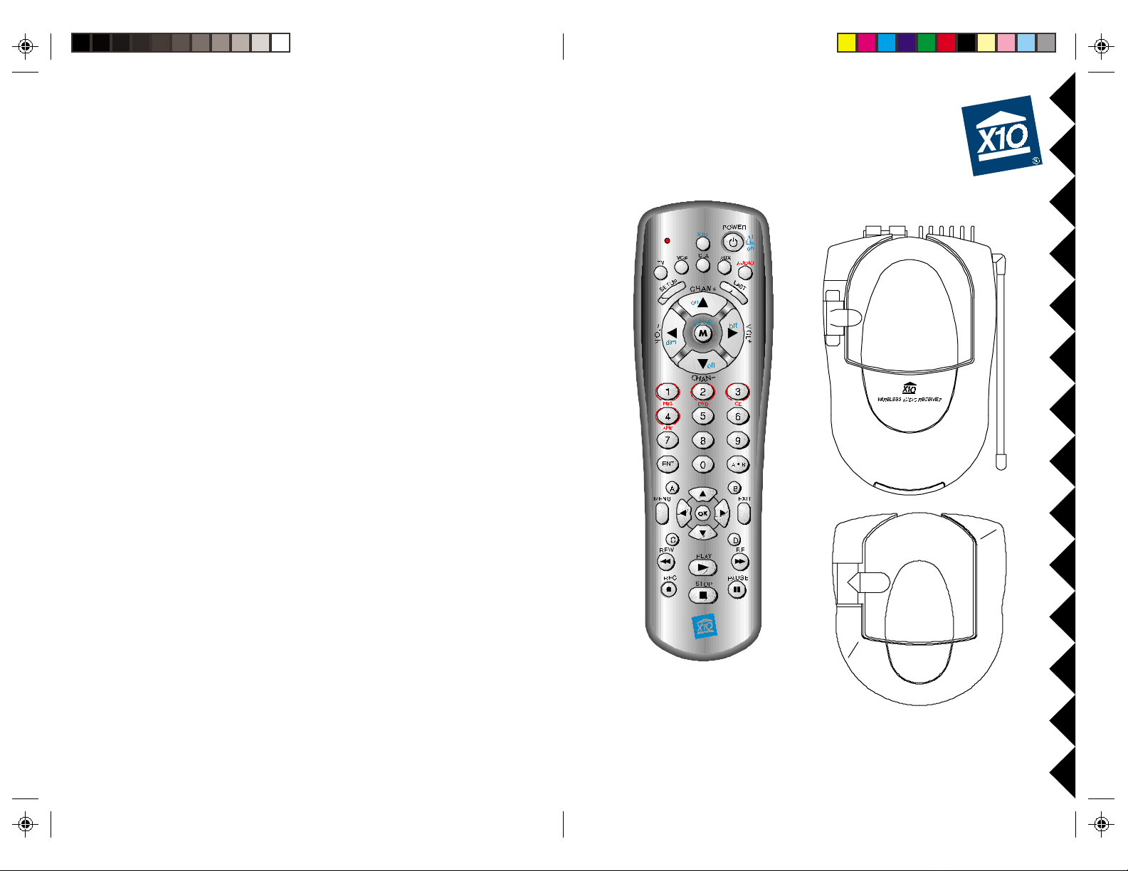
Your Wireless Audio Sender kit consists of a Sender base unit which
connects to the audio out jack on any audio source, a Receiver unit
with built-in speaker drivers to which you connect your own
speakers,* and a remote control that lets you control the volume,
balance, bass, treble, etc. The Audio Sender converts the audio
signal from your CD player, stereo, PC sound card, etc. into a radio
frequency (RF) signal and transmits it (even through walls) to the
Audio Receiver unit. The Audio Receiver converts the signal back to
its original form, amplifies the signal, and passes it to your connected
speakers. The remote is also a Universal Remote so it can also control
your TV, VCR, etc. It can also control an MP3, DVD, and CD player
in your PC when used with an additional RF receiver and software
(see page 17). It can even control lights and appliances around your
home when used with X10 Modules (see pages 24 and 25).
Place the receiver and speakers on your deck for example, and listen
to high quality audio outside while you're having a barbecue. Do not
leave the unit outside however, see below.
WW
ARNING:ARNING:
W
ARNING:
WW
ARNING:ARNING:
To reduce the risk of fire or electric shock, do not expose this product
to rain or moisture.
THIS DEVICE COMPLIES WITH PART 15 OF THE FCC RULES.
OPERATION IS SUBJECT TO THE FOLLOWING TWO CONDITIONS:
(1)THIS DEVICE MAY NOT CAUSE HARMFUL INTERFERENCE, AND
(2)THIS DEVICE MUST ACCEPT ANY INTERFERENCE RECEIVED, INCLUDING
INTERFERENCE THAT MAY CAUSE UNDESIRED OPERATION.
This equipment generates and uses radio frequency energy, and if not installed and
used properly, that is, in strict accordance with the manufacturers instructions, it may
cause interference to radio and television reception. It has been type tested and found
to comply with the limits for remote control devices in accordance with the
specifications in Sub-Parts B and C of Part 15 of FCC Rules, which are designed to
provide reasonable protection against such interference in a residential installation.
However, there is no guarantee that interference will not occur in a particular
installation. If this equipment does cause interference to radio or television reception,
which can be determined by unplugging the equipment, try to co rr ect the interference
by one or more of the following measures.
• Reorient the antenna of the radio/TV experiencing the interference.
• Relocate the equipment with respect to the radio/TV.
• Move the equipment away from the radio/TV.
• Plug the equipment into an outlet on a different electrical circuit from the radio/TV
experiencing the interference.
• If necessary, consult your local Dealer for additional suggestions.
NOTE:NOTE:
NOTE: Modifications to this product will void the user's authority to operate this
NOTE:NOTE:
equipment.
* You can use any speakers rated at 4 to 8 Ohms, and a minimum
power rating of 10W.
22
2
22
33
3
33
Page 3
CC
ONTENTSONTENTS
C
ONTENTS
ONTENTSONTENTS
CC
C C
ONTROLSONTROLS
C
ONTROLS
ONTROLSONTROLS
C C
ANDAND
AND
ANDAND
C C
ONNECTIONSONNECTIONS
C
ONNECTIONS
ONNECTIONSONNECTIONS
C C
CONTROLS AND CONNECTIONS .................................................... 5
ENDER............................................................................... 6
S
R
ECEIVER ............................................................................. 7
C
ONNECTING UP ...................................................................... 8
OOKING UP THE SENDER........................................................ 8
H
H
OOKING UP THE RECEIVER ...................................................... 9
INE TUNING YOUR SYSTEM ........................................................ 10
F
EMOTE CONTROL ................................................................... 11
R
NSTALLING THE BATTERIES ....................................................... 11
I
ATTERY SAVER .................................................................... 11
B
ODE SAVER ...................................................................... 11
C
B
UTTON DESCRIPTIONS........................................................... 12
ONTROLLING THE AMPLIFIER/SPEAKER DRIVER ............................. 14
C
ONTROLLING YOUR TV, VCR, CABLE BOX, ETC. ........................ 15
C
EARCHING FOR CODES ......................................................... 16
S
DENTIFYING CODES .............................................................. 16
I
ONTROLLING PC FUNCTIONS (MP3, DVD, CD, ETC.) ................... 17
C
OME CONTROL ..................................................................... 18
H
ONTROLLERS AND MODULES .................................................. 18
C
OUSE CODES AND UNIT CODES .............................................. 19
H
ETTING UP A TRANSCEIVER MODULE ......................................... 10
S
ETTING UP A LAMP MODULE .................................................. 20
S
ONTROLLING X10 MODULES ................................................ 21
C
HANGING THE X10 HOUSE CODE ........................................ 22
C
ONTROLLING AN IR MINI CONTROLLER (IR543) ........................ 2 3
C
XPANDING YOUR SYSTEM .......................................................... 24
E
ROUBLESHOOTING ................................................................... 26
T
SS
ENDERENDER
S
ENDER
ENDERENDER
SS
((
TOPTOP
(
TOP
TOPTOP
((
V V
V
V V
IEWIEW
IEW
IEWIEW
))
)
))
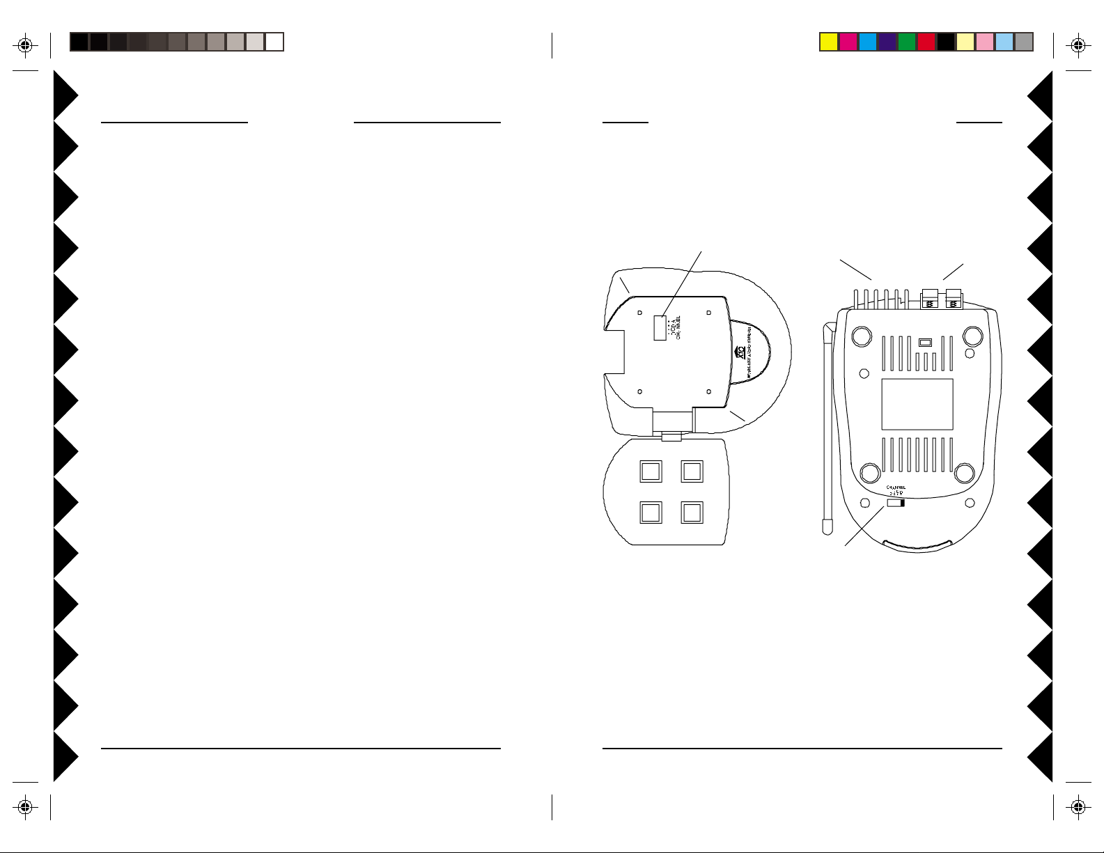
2.4 GHz
Channel Switch
Heat sink
2.4 GHz
Channel Switch
((
BOTTOMBOTTOM
(
BOTTOM
BOTTOMBOTTOM
((
connectors
RR
ECEIVERECEIVER
R
ECEIVER
ECEIVERECEIVER
RR
V V
IEWIEW
V
IEW
IEWIEW
V V
Speaker
))
)
))
44
4
44
55
5
55
Page 4
SS
ENDERENDER
ENDER
S
ENDERENDER
SS
RR
ECEIVERECEIVER
ECEIVER
R
ECEIVERECEIVER
RR
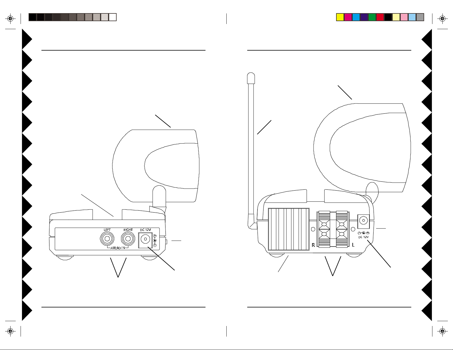
2.4 GHz Antenna
2.4 GHz
Channel Switch
(on top)
2.4 GHz
Antenna
ON-OFF
Switch
(on side)
310 MHz Antenna
(for use with UR78A
remote)
ON-OFF
Switch
(on side)
Audio In Jacks
66
6
66
Power Supply
Jack
2.4 GHz Channel
Switch
(on bottom)
Audio Out
(to speakers, 4-8
Ohm, 10W min.)
77
7
77
Power Supply
Jack
Page 5
C C
ONNECTINGONNECTING
C
ONNECTING
ONNECTINGONNECTING
C C
HH
OOKINGOOKING
OOKING
H
OOKINGOOKING
HH
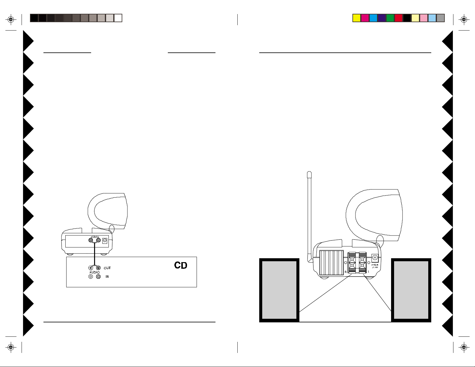
1 . Connect the jack on the audio cable (supplied) to the audio out
jack on your CD player, stereo, PC sound card, etc.
2 . Connect the red RCA plug to the socket labelled AUDIO RIGHT
and the white RCA plug to the jack labeled AUDIO LEFT on the
Audio Sender.
3 . Set the channel switch (on the TOP of the unit) to channel A (to the
RIGHT).
4. Plug the Audio Sender's Power Supply (the smaller of the two
power supplies) into a convenient 120 volt wall outlet and plug its
jack into the Audio Sender.
5 . Position the Audio Sender in a convenient location and orient the
antenna so that the flat side points in the direction of the room
where you will be installing the Audio Receiver/Speaker Driver.
THETHE
THE
THETHE
A A
A
A A
UPUP
UP
UPUP
UDIOUDIO
UDIO
UDIOUDIO
S S
S
S S
ENDERENDER
ENDER
ENDERENDER
U U
U
U U
PP
P
PP
HH
OOKINGOOKING
OOKING
H
OOKINGOOKING
HH
1 . Using speaker wire (not included) connect the left channel output
to your left speaker and the right channel output to your right
speaker (speakers not included). You can use any speakers rated
at 4 to 8 Ohms, and a minimum power rating of 10W.
2 . Set the channel switch (on the BOTTOM of the unit) to channel A
(to the LEFT).
3. Plug the Audio Receiver's Power Supply (the larger of the two
power supplies) into a 120 volt wall outlet and plug its jack into
the Audio Receiver.
4 . Position the Audio Receiver in a convenient location and orient
the antenna so that the flat side points in the direction of the
room where you set up the Audio Sender.
THETHE
THE
THETHE
A A
A
A A
UPUP
UP
UPUP
UDIOUDIO
UDIO
UDIOUDIO
R R
R
R R
ECEIVERECEIVER
ECEIVER
ECEIVERECEIVER
88
8
88
99
9
99
Page 6

F F
F
F F
The Wireless Audio Sender usually works best with the flat faces of
the antennas on the Sender and Receiver units facing each other (i.e.
in “Line of sight” - see diagram below). Sometimes, however,
reflections and other effects in your home may affect the signal so
that some adjustment of either the Sender or Receiver antenna might
be necessary to get the best signal.
INEINE
INE
INEINE
T T
T
T T
UNINGUNING
UNING
UNINGUNING
YOURYOUR
YOUR
YOURYOUR
S S
S
S S
YSTEMYSTEM
YSTEM
YSTEMYSTEM
TT
UR78A R UR78A R
HEHE
T
UR78A R
HE
HEHE
TT
UR78A R UR78A R
The UR78A Remote lets you control practically every audio/video
product in your home. It has IR technology that lets you control your
TV, VCR, Cable and CD or DVD player, and RF technology that lets
you control the VR32A wireless receiver/speaker driver. This lets
you control, the volume, balance, bass, treble, etc. of the speakers
connected to the VR32A from anywhere inside or outside your home.
It can also control an MP3, DVD, and CD player in your PC when
used with an additional RF receiver and software (see page 17).
EMOTEEMOTE
EMOTE
EMOTEEMOTE
II
FF
YOUYOU
I
II
Check that the CHANNEL slide switch (labeled A, B, C, D) on both
units is set to the same letter.
II
I
II
Try changing the channel on both units. Do this by adjusting the
CHANNEL slide switch on each unit to any position from A to C.
Make sure both units are set to the same channel.
AREARE
F
YOU
ARE
FF
YOUYOU
AREARE
FF
THETHE
SIGNALSIGNAL
F
THE
SIGNAL
FF
THETHE
SIGNALSIGNAL
NOTNOT
NOT
NOTNOT
GETTINGGETTING
GETTING
GETTINGGETTING
ISIS
IS
ISIS
POORPOOR
POOR
POORPOOR
ANYANY
ANY
ANYANY
, ,
OROR
THERETHERE
,
OR
THERE
OROR
THERETHERE
, ,
SIGNALSIGNAL
SIGNAL
SIGNALSIGNAL
ISIS
IS
ISIS
AA
TT
ALLALL
A
T
ALL
AA
TT
ALLALL
INTERFERENCEINTERFERENCE
INTERFERENCE
INTERFERENCEINTERFERENCE
II
NSTNST
I
NST
NSTNST
II
1.1.
1. Push the tab and lift off the battery cover.
1.1.
2.2.
2. Insert four AAA alkaline batteries, taking
2.2.
BB
AA
B
A
AA
BB
Your UR78A remote will automatically “time-out” if the keys are
depressed for more than two minutes. This will save your batteries
should your remote get stuck in a place where the keys remain
depressed (e.g., between the sofa cushions).
CC
C
CC
You will have up to 90 seconds to change the batteries in your
remote without losing codes you have programmed. However, do not
press any buttons until batteries are installed in the remote. If buttons
are pressed without batteries in the remote, all codes will be lost.
S S
S
S S
YY
Y
YY
THETHE
THE
THETHE
S S
S
S S
AA
VERVER
A
VER
AA
VERVER
AA
A
AA
BABA
BA
BABA
VERVER
VER
VERVER
(I (I
(I
(I (I
TTERIESTTERIES
TTERIES
TTERIESTTERIES
MPORMPOR
MPOR
MPORMPOR
TT
ANTANT
T
ANT
TT
ANTANT
))
)
))
ALLINGALLING
ALLING
ALLINGALLING
care to match the + and - marks in the
battery compartment.
TTERTTER
TTER
TTERTTER
ODEODE
ODE
ODEODE
1010
10
1010
1111
11
1111
Page 7

S S
ETTINGETTING
S
ETTING
ETTINGETTING
S S
BB
B
BB
INDICAINDICA
INDICA
INDICAINDICA
The indicator light flashes when you press any button.
POWERPOWER
POWER
POWERPOWER
Works the same as your original r emote.
TVTV
TV
TVTV
Used to select the device to control (AUDIO selects the VR32A
Wireless Amplifier/Speaker Driver).
SET UPSET UP
SET UP
SET UPSET UP
Used for programming the remote.
LASTLAST
LAST
LASTLAST
Selects the last channel viewed on your TV, VCR, or Cable Box.
VOLUME +/-VOLUME +/-
VOLUME +/-
VOLUME +/-VOLUME +/-
Works like your original r emote. Also, after you first press AUDIO
followed by AMP (button 4) VOL+ increases volume on both channels
VOL- decreases volume on both channels on the VR32A Amplifier/
Speaker Driver.
CHANNEL +/-CHANNEL +/-
CHANNEL +/-
CHANNEL +/-CHANNEL +/-
Works like your original r emote. Also, after you first press AUDIO
followed by AMP (button 4) CH+ adjusts balance to right channel,
reduces left channel volume; CH- adjusts balance to left channel,
reduces right channel volume on the VR32A.
MUTEMUTE
MUTE
MUTEMUTE
Works the same as your original remote. Also, after you first pr ess
AUDIO followed by AMP (button 4) MUTE toggles the audio output
ON/OFF on the VR32A.
0-90-9
0-9
0-90-9
Used as your original remote and to enter device codes.
D D
UTTONUTTON
UTTON
UTTONUTTON
, VCR, CBL, AUX, AUDIO, VCR, CBL, AUX, AUDIO
, VCR, CBL, AUX, AUDIO
, VCR, CBL, AUX, AUDIO, VCR, CBL, AUX, AUDIO
ESCRIPTIONSESCRIPTIONS
ESCRIPTIONS
D
ESCRIPTIONSESCRIPTIONS
D D
TOR LIGHTTOR LIGHT
TOR LIGHT
TOR LIGHTTOR LIGHT
U U
U
U U
PP
P
PP
THETHE
THE
THETHE
R R
EMOTEEMOTE
R
EMOTE
EMOTEEMOTE
R R
Also, after you first press AUDIO, buttons 1, 2, and 3 perform as
function buttons for MP3, DVD and CD respectively when used with
an optional X10 wireless receiver and PC software (see page 17).
Also, after you first press AUDIO, button 4 (AMP) performs as a
function button to select the VR32A Amplifier/Speaker Driver (see
page 14).
ENTERENTER
ENTER
ENTERENTER
Same as your original remote.
A-BA-B
A-B
A-BA-B
Toggles between TV and Video Mode.
MENUMENU
MENU
MENUMENU
Access the Menu function of the device you are controlling (if
available).
EXIT EXIT
EXIT
Used to exit Menu functions.
EXIT EXIT
NANA
VIGAVIGA
TION ARROWSTION ARROWS
NA
VIGA
TION ARROWS
NANA
VIGAVIGA
TION ARROWSTION ARROWS
Used to navigate and adjust menu items of the device you are
controlling. Also, after you first press AUDIO followed by AMP
(button 4) the UP navigation button increases bass, DOWN decreases
bass, RIGHT increases treble, LEFT decreases treble on the VR32A
Amplifier/Speaker Driver.
OKOK
OK
OKOK
Selects menu items of the device you are controlling. Also, after you
first press AUDIO followed by AMP (button 4) OK restores the
default settings for balance, bass, and treble on the VR32A
Amplifier/Speaker Driver.
PLAPLA
YY
, REW, FF, REW, FF
, STOP, STOP
, P, P
PLA
Y
, REW, FF
PLAPLA
YY
, REW, FF, REW, FF
Work the same as on your original remote. You must press the REC
button twice to begin recording.
A, B, C, DA, B, C, D
A, B, C, D
A, B, C, DA, B, C, D
Used for extra functions in certain modes.
, STOP
, STOP, STOP
AUSE, RECAUSE, REC
, P
AUSE, REC
, P, P
AUSE, RECAUSE, REC
1212
12
1212
1313
13
1313
Page 8

CC
ONTROLLINGONTROLLING
ONTROLLING
C
ONTROLLINGONTROLLING
CC
VR32A A VR32A A
THETHE
THE
VR32A A
THETHE
VR32A A VR32A A
MPLIFIERMPLIFIER
MPLIFIER
MPLIFIERMPLIFIER
/S/S
/S
/S/S
PEAKERPEAKER
PEAKER
PEAKERPEAKER
D D
D
D D
RIVERRIVER
RIVER
RIVERRIVER
Press and release the AUDIO button. The LED blinks once. Then press
and release button 4 (AMP). This puts the remote into the mode to
control the VR32A Wireless Amplifier/Speaker Driver.
1.1.
1. Press and release the
1.1.
AUDIO button. The
LED blinks once.
3.3.
3. Press VOL+ to
3.3.
increase volume on
both channels; VOLto decrease volume
on both channels on
the VR32A
Amplifier/Speaker
Driver.
4.4.
4. Press CH+ to adjust
4.4.
balance to right
channel, reduces left
2.2.
2. Press and release
2.2.
button 4 (AMP).
navigation button
to increase bass,
DOWN to
decrease bass.
7.7.
7. Press RIGHT
7.7.
8.8.
8. Press OK to restore
8.8.
the default settings
for balance, bass,
and treble.
channel volume; CHto adjust balance to
left channel, reduces
right channel volume.
5.5.
5. Press MUTE to toggle
5.5.
the audio output
ON/OFF.
6.6.
6. Press the UP
6.6.
navigation button to
increase treble, LEFT
to decrease treble.
SS
S
SS
1.1.
1. Turn on the device you want to control (TV, VCR,
1.1.
2.2.
2. Press and hold SETUP until the LED indicator
2.2.
3.3.
3. Press and release mode button for the device
3.3.
4.4.
4. Enter the 3 digit Code from the Library Code
4.4.
5.5.
5. Point the remote at the device and press the
5.5.
6.6.
6. Turn your device on and press CHANNEL+. If
6.6.
TV TV
ETTINGETTING
UPUP
ETTING
UP
ETTINGETTING
cable box, etc.).
lights steadily. Release the SETUP button.
you want to control (TV, VCR, Cable or AUX).
The LED blinks once. (See notes below).
Table (separate sheet). The LED tur ns off after
the last digit entered.
POWER button. Y our device should turn off.
the device responds, setup is complete.
UPUP
FORFOR
FOR
FORFOR
, VCR, C, VCR, C
TV
, VCR, C
TV TV
, VCR, C, VCR, C
ABLEABLE
ABLE
ABLEABLE
, ,
,
, ,
ANDAND
AND
ANDAND
AUX AUX
AUX
AUX AUX
Notes:
1. The TV mode key can only be used to store TV codes but you can
store a code for ANY device under either the VCR, CBL, or AUX
mode key. E.G., you can store a Cable code under the VCR key, or
a Satellite code under the Cable key, etc.
2. If your TV/VCR/Cable Box does not respond, tr y the other codes
for your brand. If it still doesn’t respond, try the Code Search
method on page 16.
3. If the LED blinked rapidly when you entered the code, you may
have entered an invalid code. Recheck the code in the code list
(separate sheet) and try again.
4. If some buttons do not operate your equipment, try one of the
other codes for your brand.
5. When searching for a code (page 16) you might have to press
CHANNEL+ many times (50+). If the device does not have a
Channel Up function, use the PLAY button (VCR only) or the
POWER button.
1414
14
1414
1515
15
1515
Page 9

SS
EARCHINGEARCHING
EARCHING
S
EARCHINGEARCHING
SS
1.1.
1. Turn on the device you want to control.
1.1.
2.2.
2. Press and hold SETUP until the LED indicator
2.2.
lights steadily. Release the Setup button.
3.3.
3. Press the mode button that matches the equip-
3.3.
ment you want to control (TV, VCR, Cable, AUX).
The LED blinks once.
4.4.
4. Press CHANNEL + repeatedly (note 5, page 15)
4.4.
until the device to be controlled changes
channel.
If you accidentally go past the code, press
CHANNEL - repeatedly until the channel
changes again.
5.5.
5. Press and release the ENTER button to complete
5.5.
the setup.
The above assumes that you want to store VCR codes under the VCR
button, Cable codes under CBL, etc. If you want to store a VCR code
under CBL, etc., first follow the procedure on page 15 and try ANY
CBL code from the code tables, e.g. press CBL in step 3, page 15, and
then enter ANY VCR code. Then follow the steps above.
F F
C C
OROR
ODESODES
OR
ODES
F
C
OROR
ODESODES
F F
C C
CC
ONTROLLINGONTROLLING
C
ONTROLLING
ONTROLLINGONTROLLING
CC
The UR78A remote can also control an MP3, DVD, and CD player in
your PC when used with an additional RF receiver and software. You
will need to purchase an MR26A receiver which connects to your
PC's serial port. You then download the software (called Boom) fr om
X10's Web Site (www.x10.com). You will then be able to control a
DVD or CD player in your PC as well as being able to control MP3
players such as MusicMatch, RealJukeBox, WinAmp, etc., remotely
from anywhere inside or outside your home.
The AUDIO button is also a PC button so to access your PC you just
press AUDIO (PC) followed by button 1 (MP3) or button 2 (DVD) or
button 3 (CD). You can then use buttons such as Play, Stop, Pause, FF,
REW, etc. to control the DVD, CD, or MP3 player in your PC.
When used in conjunction with the VT35A Audio Transmitter, a nd
VR32A Audio Receiver/Speaker Driver, you will be able to listen to
MP3 files stored in your PC while sitting outside having a barbecue.
PC F PC F
PC F
PC F PC F
UNCTIONSUNCTIONS
UNCTIONS
UNCTIONSUNCTIONS
II
DENTIFYINGDENTIFYING
DENTIFYING
I
DENTIFYINGDENTIFYING
II
1.1.
1. Press and hold SETUP until the LED indicator lights steadily. Release the Setup button.
1.1.
2.2.
2. Press the mode button that matches the equipment you want to identify (TV , VCR,
2.2.
CBL). The LED blinks once.
3.3.
3. Press and release SETUP. The LED blinks once.
3.3.
4.4.
4. To find the first digit, press each number button from 0 to 9 until the LED blinks. The
4.4.
number you pressed is the first digit of the code.
5.5.
5. Press each number button from 0 to 9 again as above to find the second digit.
5.5.
6.6.
6. Press each number button in turn to find the third digit. When the third digit has been
6.6.
found, the LED goes out.
C C
C
C C
ODESODES
ODES
ODESODES
FOUNDFOUND
FOUND
FOUNDFOUND
USINGUSING
USING
USINGUSING
THETHE
THE
THETHE
1616
16
1616
S S
S
S S
EARCHEARCH
EARCH
EARCHEARCH
P P
ROCEDUREROCEDURE
ROCEDURE
P
ROCEDUREROCEDURE
P P
Pressing AUDIO (PC) followed by 1
(MP3) or 2 (DVD) or 3 (CD)
accesses your PC, when used with
the optional MR26A receiver and
Boom software.
1717
17
1717
Page 10

HH
H
HH
The UR78A remote can also control lights and appliances around
your home when you purchase additional X10 accessories (See
pages 24 and 25).
CC
ONTROLLERSONTROLLERS
ONTROLLERS
C
ONTROLLERSONTROLLERS
CC
The first thing you need to understand is that there
are two different devices you need to control your
home; Controllers and Modules. Any light or
appliance that you want to control is plugged into a
Module and that Module is then plugged into a
standard AC outlet.
Modules receive commands from Controllers.
Examples include the Lamp Module (sold
separately). The Transceiver Module (also sold
separately) is another example (although it also
doubles as a controller as described later).
Controllers are also plugged into standard wall
outlets and send commands to Modules over your
existing electrical wiring in your home without
affecting your electricity in any way.
The Transceiver Module works as a controller when it is
used with a remote control such as the UR78A Remote.
When the Transceiver Module receives a command
from a remote it sends digital signals over your
existing house wiring to a Module which receives the
signals and executes the command.
The remote uses radio frequency (RF) signals to send
commands to the Transceiver module. RF signals
can go right through walls, so you can use the
remote to control lights or appliances from
anywhere in your home.
ANDAND
AND
ANDAND
M M
M
M M
OMEOME
OME
OMEOME
ODULESODULES
ODULES
ODULESODULES
C C
ONTROLONTROL
C
ONTROL
ONTROLONTROL
C C
HH
H
HH
Each Module has a specific address made up of a House Code (red
dial on the face of the Module) and a Unit Code (black dial on the
face of the Module).
The Controller first sends an address
and then a command on the AC
power lines. Only the Module with a
matching address will execute the
command. If more than one Module
has the same address, both Modules
will execute the command.
Addresses are set on the Module by turning the two dials on the front
of the Module to the desired letter and number (using a small
screwdriver or a coin). The House Code is selected from the letters A
through P, and the Unit Code is selected from the numbers 1 - 16.
TT
T
TT
The Transceiver Module (sold separately) receives radio frequency
(RF) commands from the UR78A Remote to operate a lamp or
appliance plugged into it. The Transceiver Module also passes on
commands over your house wiring to control other X10 modules (also
sold separately). Note that unlike the Lamp Module you cannot dim
or brighten a lamp connected to the Transceiver Module.
You should locate the Transceiver Module centrally in your home for
maximum range when controlled by the UR78A Remote.
1.1.
1 . Set the House Code
1.1.
C C
OUSEOUSE
OUSE
OUSEOUSE
RANSCEIVERRANSCEIVER
RANSCEIVER
RANSCEIVERRANSCEIVER
to ‘A.’
C
C C
ODESODES
ODES
ODESODES
M M
M
M M
ANDAND
AND
ANDAND
ODULEODULE
ODULE
ODULEODULE
U U
C C
NITNIT
NIT
U
C
NITNIT
U U
C C
2.2.
2. Plug a lamp or
2.2.
appliance into the
Transceiver Module.
ODESODES
ODES
ODESODES
UNIT CODE
DIAL
HOUSE CODE
DIAL
3.3.
3. Plug the Transceiver
3.3.
Module into an AC
outlet. Fully extend
the antenna.
1818
18
1818
1919
19
1919
Page 11

LL
M M
AMPAMP
AMP
L
AMPAMP
LL
The Lamp Module (sold separately) can be used to control any
incandescent lamp rated up to 300W. It is not suitable for other types
of lamp such as fluorescent or energy saving lamps, or lamps which
include a dimmer control.
Caution: Do not connect an appliance such as a coffee pot or heater
to the Lamp Module. It may damage the module and the appliance
and could cause a fire hazard. Use an Appliance Module instead.
1.1.
1 . Set the House Code
1.1.
to ‘A’ and the Unit
Code to ‘2.’
M
M M
ODULEODULE
ODULE
ODULEODULE
2.2.
2. Plug a lamp into
2.2.
the Lamp Module.
3.3.
3. Plug the Lamp
3.3.
Module into a
convenient AC
outlet.
CC
ONTROLLINGONTROLLING
C
ONTROLLING
ONTROLLINGONTROLLING
CC
If you have purchased and installed a Transceiver Module, you can
control it and other X10 modules as follows:
1.1.
1. Press and release the X10 button.
1.1.
2.2.
2. Use the number buttons to enter the Unit
2.2.
Code number of the chosen module. (You
do not need to enter ‘0’ first for a single
digit number.)
3.3.
3. Press the appropriate button for the
3.3.
function you require (see below).
X10 FUNCTIONS:
On = CHANNEL +
Off = CHANNEL –
Bright = VOLUME +
Dim = VOLUME –
All Lamps On = POWER
All Modules Off = MUTE
X10 M X10 M
X10 M
X10 M X10 M
ODULESODULES
ODULES
ODULESODULES
2020
20
2020
Note: You cannot dim or brighten an Appliance Module. If the
module was off and you press Bright or Dim (VOLUME+ or
VOLUME-) this will simply turn the module on.
2121
21
2121
Page 12

CC
HANGINGHANGING
HANGING
C
HANGINGHANGING
CC
THETHE
THE
THETHE
X10 H X10 H
X10 H
X10 H X10 H
OUSEOUSE
OUSE
OUSEOUSE
C C
C
C C
ODEODE
ODE
ODEODE
CC
ONTROLLINGONTROLLING
ONTROLLING
C
ONTROLLINGONTROLLING
CC
IR MIR M
IR M
IR MIR M
INIINI
INI
INIINI
C C
C
C C
ANAN
OPTIONALOPTIONAL
AN
OPTIONAL
ANAN
OPTIONALOPTIONAL
ONTROLLERONTROLLER
ONTROLLER
ONTROLLERONTROLLER
(IR543) (IR543)
(IR543)
(IR543) (IR543)
The UR78A Remote defaults to House Code A, and in most cases you
will not need to change this unless you are experiencing interference
from a neighboring X10 system.
1.1.
1. Press and release the X10 button.
1.1.
2.2.
2. Press and hold SETUP until the LED
2.2.
indicator lights steadily. Release the
Setup button.
3.3.
3. Use the number buttons to enter the
3.3.
number equivalent to the chosen House
Code (1=A, 2=B ..16=P).
4.4.
4. Press the ENTER button to confirm the House
4.4.
Code. The LED turns off.
If you already own an IR Mini Controller, Model IR543, you will need
to change the X10 Home Automation code in the UR78A remote to
use it. The code for standard X10 RF Home Automation is 999. The
code to control the IR Mini Controller is 998. To change the code:
2.2.
2. Press and release
1.1.
1. Press and hold
1.1.
SETUP until the LED
indicator lights
steadily. Release the
SETUP button.
2.2.
the X10 button.
3.3.
3. Enter 998 to control
3.3.
an IR543, IR Mini
Controller, or 999
for standard X10
control. The LED
turns off after the last
digit entered.
Note: The House Code you choose must
match the House Code on the Transceiver
and Modules you are using it with.
2222
22
2222
Note: In most cases, you will not need to use the IR Mini Controller to
receive commands from the UR78A Remote - the RF Transceiver
Module does this for you and has the added advantage of working
through walls. You can if you wish control the IR Mini Controller and
the Transceiver Module at the same time. To do this store code 999
under the X10 key and store 998 under any other key (except TV).
See page 27 for more info on using an IR543.
2323
23
2323
Page 13

A
I
EM
O
C
GK
•
•
•
•
•
•
•
•
1
9
51
3
1
5
3
71
1
•
•
•
•
•
•
•
UNIT
R
e
m
o
t
e
C
h
i
m
e
HOUSE
1
9
513
A
I
EM
CONTINUOUS
MOMENTARY
U
N
I
V
E
R
S
A
L
M
O
D
U
L
E
O
N
O
F
F
SOUNDER & RELAY
RELAY ONLY
SOUNDER ONLY
P
o
w
e
r
A
d
a
p
te
r
OFF
T
h
e
r
m
o
s
t
a
t
S
e
t
-
B
a
c
k
C
o
n
t
r
o
l
l
e
r
LO M HI
1
9
51
3
A
I
EM
A
I
EM
•
•
••
1
9
513
•
•
••
CONTROLLED
A
I
EM
•
•
••
1
9
51
3
•
•
••
Heavy Duty
A
ppliance M
odule
U
N
IT
H
O
U
S
E
EE
1
9
51
3
A
I
EM
AB 123
IN
P
U
T
M
O
D
E
P
O
W
E
R
F
L
A
S
H
I
N
T
E
R
F
A
C
E
T
E
S
T
A
L
L U
N
IT
S
O
F
F
E
EE
XPXP
XP
XPXP
ANDINGANDING
ANDING
ANDINGANDING
YOURYOUR
YOUR
YOURYOUR
S S
YSTEMYSTEM
S
YSTEM
YSTEMYSTEM
S S
The modules illustrated below represent just a few of the wide range
of X10 compatible modules you can choose from to expand your
Home Automation system. They are available from electrical outlets,
department stores and mail order catalogs.
X10 Home Automation products also integrate with X10 security
systems, so you can use the security remotes that come with them to
control macros and flash lights when the security system is tripped.
For more information on these and many other X10 products, visit our
W eb Site at:
WWW.X10.COM
Replace your existing wall switches with the Wall
Switch Module WS467. Installs like a regular dimmer .
On/Off and Bright/Dim functions. Other models
available for 3-way and fluorescent lighting.
Control a ceiling light, closet light, etc. with the convenient
Screw-in Lamp Module LM15A.
Replace existing AC wall outlets with the Receptacle
Module SR227. Has one 15A/1800W controlled
outlet and one outlet which is always on.
Use the
Mini Timer MT10A Mini Timer MT10A
Mini Timer MT10A to program up to 4
Mini Timer MT10A Mini Timer MT10A
X10 Modules to go on and off up to twice a day.
The Dual Floodlight Motion Detector PR511 turns
on at dusk and/or when it detects movement,
and sends X10 signals to control other modules,
or trigger ActiveHome macros.
Fit a Wireless Wall Switch SS13A/SS15A
anywhere you need an extra switch - with no
wires. Sends commands to the Transceiver
Module just like a remote.
The PowerFlash Module PF284 connects to dry contact or
low voltage alarm terminals on your burglar alarm system
and flashes X10 controlled lights when it is triggered.
Switch entrance or garage lights on
from your car with the convenient
Keychain Remote KR21A.
Use a controller to trigger the Remote Chime Module
SC546 to call Dad up for dinner, or warn people
you’re about to turn on the sprinklers.
Use the isolated contacts on the Universal Module
UM506 to control pool pumps, sprinklers, drapes
and other low voltage equipment. Includes built
in warning beeper.
The Thermostat Setback Controller TH2807
mounts below your existing thermostat to reduce
the room temperature at night or at the times
you set (with the MT10A Timer) to save energy .
No wiring needed to your existing thermostat.
Plug in a Heavy Duty Module HD245 to control
220V appliances such as air conditioners and
water heaters.
Also compatible with FirAlso compatible with Fir
Also compatible with Fir
Also compatible with FirAlso compatible with Fir
See wwwSee www
See www
See wwwSee www
.x10.com for details..x10.com for details.
.x10.com for details.
.x10.com for details..x10.com for details.
eCracker Computer IntereCracker Computer Inter
eCracker Computer Inter
eCracker Computer IntereCracker Computer Inter
face.face.
face.
face.face.
2424
24
2424
2525
25
2525
Page 14

TT
ROUBLESHOOTINGROUBLESHOOTING
T
ROUBLESHOOTING
ROUBLESHOOTINGROUBLESHOOTING
TT
TT
T
TT
ALLALL
ALL
ALLALL
HEHE
HE
HEHE
R R
R
R R
::
:
::
EMOTEEMOTE
EMOTE
EMOTEEMOTE
WONWON
WON
WONWON
’’
TT
CONTROLCONTROL
’
T
CONTROL
TT
CONTROLCONTROL
’’
YOURYOUR
YOUR
YOURYOUR
A/V A/V
A/V
A/V A/V
EQUIPMENTEQUIPMENT
EQUIPMENT
EQUIPMENTEQUIPMENT
, ,
’’
OROR
DOESNDOESN
,
DOESN
DOESNDOESN
’
’’
OR
OROR
, ,
TT
T
TT
WORKWORK
WORK
WORKWORK
AA
TT
A
T
AA
TT
• Use manual controls or the original remote control to confirm the
equipment is working properly.
• Be sure you pressed the device key for the device you want to
control.
• Reenter the code for your A/V product from the code listings on
the separate sheet included.
• Try searching for codes as described on page 16.
• Replace the Remote’s batteries.
TT
R R
’’
T
TT
DD
D
DD
HEHE
HE
HEHE
RIVERRIVER
RIVER
RIVERRIVER
R
R R
EMOTEEMOTE
EMOTE
EMOTEEMOTE
::
:
::
WONWON
WON
WONWON
TT
CONTROLCONTROL
’
T
CONTROL
TT
CONTROLCONTROL
’’
YOURYOUR
YOUR
YOURYOUR
VR32A W VR32A W
VR32A W
VR32A W VR32A W
IRELESSIRELESS
IRELESS
IRELESSIRELESS
A A
A
A A
MPLIFIERMPLIFIER
MPLIFIER
MPLIFIERMPLIFIER
/S/S
/S
/S/S
PEAKERPEAKER
PEAKER
PEAKERPEAKER
• Make sure your press the Audio button then the AMP button
(button 4) before you try to control the VR32A.
• If you have reprogrammed the Audio button to control something
else, program it back to Audio operation as follows:
The default code for the Audio button is 013. You might want to
change this to use the Audio button to control something else, like a
Laser Disk player, for example. Note however that if you do this the
Audio button will not let you access the MP3, DVD, CD, and AMP
functions (1, 2, 3, 4 buttons). To reprogram the Audio button to once
again access these functions:
1. Press and hold SETUP until the LED indicator remains on.
2. Release SETUP.
3. Press and release the Audio button.
4. Enter the 3 digit code 0, 1, 3.
5. The LED indicator turns off after the last digit is entered.
II
FF
YOUYOU
AREARE
I
F
YOU
ARE
FF
YOUYOU
AREARE
II
NOTNOT
NOT
NOTNOT
GETTINGGETTING
GETTING
GETTINGGETTING
ANYANY
ANY
ANYANY
SOUNDSOUND
SOUND
SOUNDSOUND
AA
TT
ALLALL
FROMFROM
A
T
ALL
FROM
AA
TT
ALLALL
FROMFROM
THETHE
THE
THETHE
VR32A VR32A
VR32A
VR32A VR32A
• Check that the CHANNEL slide switch (labeled A, B, C, D) on both
units is set to the same letter.
• Check that both the transmitter and receiver's power supplies are
plugged in. Check that the ON/OFF switch on the transmitter and
receiver are ON.
II
, ,
FF
THETHE
SOUNDSOUND
ISIS
POORPOOR
I
SOUND
SOUNDSOUND
IS
ISIS
F
THE
FF
THETHE
II
POOR
POORPOOR
OROR
,
OR
OROR
, ,
THERETHERE
THERE
THERETHERE
ISIS
INTERFERENCEINTERFERENCE
IS
INTERFERENCE
ISIS
INTERFERENCEINTERFERENCE
• Try changing the channel on both units. Do this by adjusting the
CHANNEL slide switch on each unit to any position (A, B, C, or D).
• Make sure both units are set to the same letter. Try repositioning
the antenna on each unit.
TT
HEHE
T
HE
HEHE
TT
T T
RANSCEIVERRANSCEIVER
T
RANSCEIVER
RANSCEIVERRANSCEIVER
T T
M M
M
M M
ODULEODULE
ODULE
ODULEODULE
DOESNDOESN
DOESN
DOESNDOESN
’’
TT
RESPONDRESPOND
’
T
RESPOND
TT
RESPONDRESPOND
’’
REMOTEREMOTE
REMOTE
REMOTEREMOTE
::
:
::
TOTO
THETHE
TO
THE
TOTO
THETHE
• Check the House Code on the Transceiver Module is set to ‘A.’ If
you have changed the House Code on the remote (see p. 22),
check that it matches the House Code on the Transceiver Module.
• Press the ON/OFF button on the front of the Transceiver Module
to confirm it operates the equipment connected to it.
TT
HEHE
T
HE
HEHE
TT
T T
RANSCEIVERRANSCEIVER
T
RANSCEIVER
RANSCEIVERRANSCEIVER
T T
M M
M
M M
ODULEODULE
ODULE
ODULEODULE
WORKSWORKS
WORKS
WORKSWORKS
, ,
OTHEROTHER
OTHER
OTHEROTHER
MODULESMODULES
MODULES
MODULESMODULES
BUTBUT
,
BUT
BUTBUT
, ,
DONDON
DON
DONDON
’’
TT
RESPONDRESPOND
’
T
RESPOND
TT
RESPONDRESPOND
’’
::
:
::
• Check that the Module has the same House Code as the
Transceiver Module.
• Try plugging the Module into a dif ferent outlet.
Note: if you use an RF Transceiver (such as the RR501 or TM751) to
control X10 Modules, you will be able to control up to 16
Modules. With a Transceiver, when you press 1-6-ON you tur n on
Module number 16. However, if you use an IR543, when you
press 1-6-ON you turn on Modules 1 AND 6. The IR543 can only
control 10 Modules (1-9 plus 0=10).
2626
26
2626
2727
27
2727
Page 15

12 MONTH LIMITED W12 MONTH LIMITED W
12 MONTH LIMITED W
12 MONTH LIMITED W12 MONTH LIMITED W
X10.COM A DIV. OF X10 WIRELESS TECHNOLOGY, INC. (X10) W ARRANTS
ITS PRODUCTS TO BE FREE FROM DEFECTIVE MA TERIAL AND WORKMANSHIP
FOR A PERIOD OF ONE (1) YEAR FROM THE ORIGINAL DA TE OF PURCHASE
A T RET AIL. X10 AGREES TO REPAIR OR REPLACE, AT ITS SOLE DISCRETION, A
DEFECTIVE X10 PRODUCT IF RETURNED TO X10 WITHIN THE W ARRANTY
PERIOD AND WITH PROOF OF PURCHASE.
THIS WARRANTY DOES NOT EXTEND TO ANY X10 PRODUCTS WHICH HA VE
BEEN SUBJECT TO MISUSE, NEGLECT , ACCIDENT, INCORRECT WIRING OR TO
USE IN VIOLA TION OF OPERATING INSTRUCTIONS FURNISHED BY US, NOR
EXTEND TO ANY UNITS ALTERED OR REP AIRED FOR WARRANTY DEFECT BY
ANYONE OTHER THAN X10. THIS WARRANTY DOES NOT COVER ANY
INCIDENTAL OR CONSEQUENTIAL DAMAGES AND IS IN LIEU OF ALL OTHER
W ARRANTIES EXPRESSED OR IMPLIED AND NO REPRESENTATIVE OR PERSON
IS AUTHORIZED TO ASSUME FOR US ANY OTHER LIABILITY IN CONNECTION
WITH THE SALE OF OUR PRODUCTS.
SOME STATES DO NOT ALLOW LIMITATIONS ON HOW LONG AN IMPLIED
W ARRANTY LASTS, AND/OR THE EXCLUSION OR LIMIT ATION OF INCIDENTA L
OR CONSEQUENTIAL DAMAGES SO THE ABOVE LIMITATIONS AND
EXCLUSIONS MAY NOT APPLY TO THE ORIGINAL CUSTOMER. THIS
W ARRANTY GIVES YOU SPECIFIC RIGHTS AND YOU MAY ALSO HAVE OTHER
RIGHTS WHICH VARY FROM STATE TO STATE.
IF SERVICE IS REQUIRED UNDER THIS W ARRANTY:
1. CALL 1-800-442-5065, OR VISIT WWW.X10.COM, OR E-MAIL
SALES@X10.COM.
ARRANTYARRANTY
ARRANTY
ARRANTYARRANTY
X10.com, a division of X10 Wireless Technology, Inc.
(Returns Depot), 3824 North 5th St., Suite C,
North Las Vegas, NV 89032
VK59A-12/02
 Loading...