

Page 1
™
The Big Picture
PC AUDIO/VIDEO EXTENDER SYSTEM
VT24A
VR20A
JR20A
VA23A
MODEL VK25A OWNER'S MANUAL
(INCLUDES VA23A VGA-TO-VIDEO CONVERTER,
VT24A T
JR20A MOUSE REMOTE)
RANSMITTER, VR20A RECEIVER, AND
Page 2

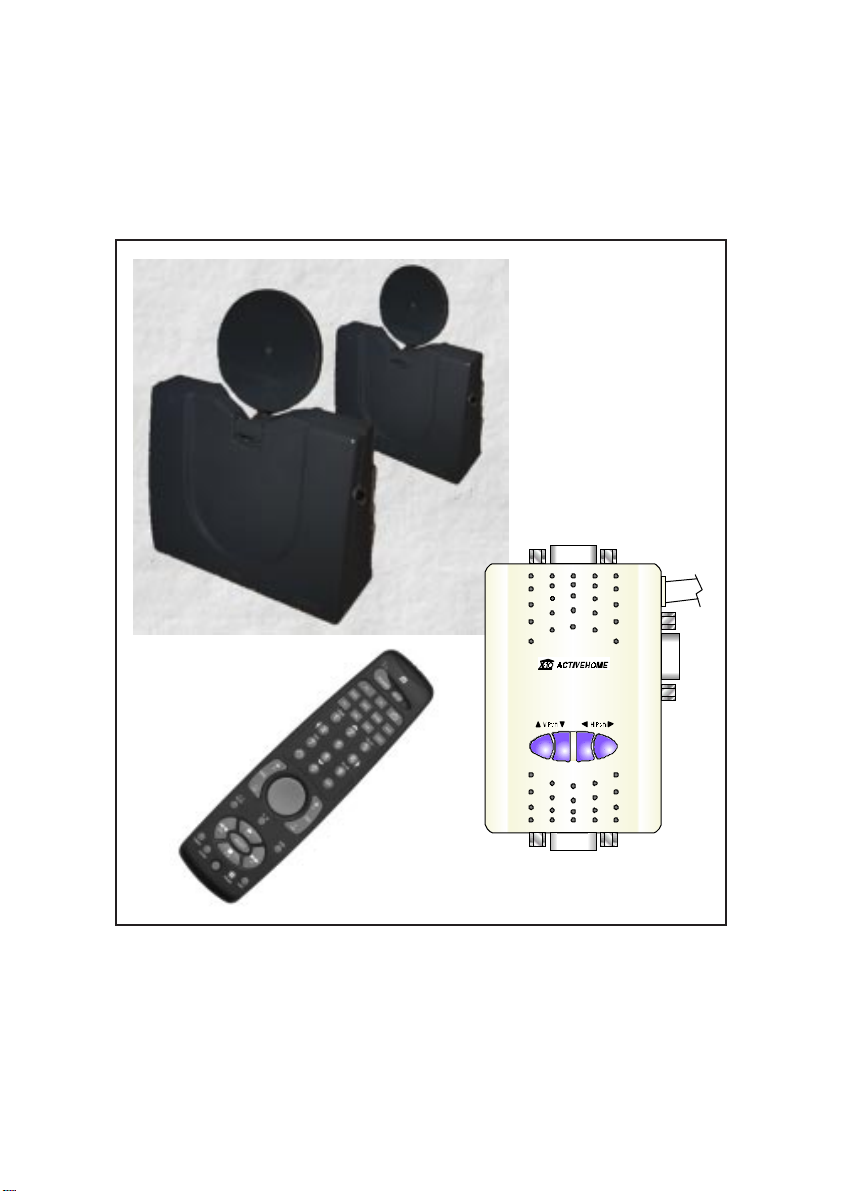
INTRODUCTION
Your Big Picture™ kit consists of a VGA to Video Converter, a Video
Transmitter, a Video Receiver, and a Wireless Mouse Remote. The
VGA to Video Converter converts the VGA signals from your PC to
Composite Video (the type of signals most TVs will accept) and also
passes the VGA signals to your regular PC monitor.
The Video Transmitter converts the video signals from the VGA to
Video Converter into a 2.4 GHz radio signal and transmits it (even
through walls) to the Video Sender Receiver. The Video Sender
Receiver converts the signals back to A/V signals which are fed
through a cable to your TV's A/V input jacks.
The Wireless Mouse Remote lets you control your PC from the room
where your TV is.
There are just a few simple steps to follow to hook up your Big Picture
kit.
WARNING:
To reduce the risk of fire or electric shock, do not expose this product
to rain or moisture.
2
Page 3

IMPORTANT SAFETY INSTRUCTIONS
1. Read Instructions - All the safety and operating instructions should be read
before the product is operated.
2. Retain Instructions - The safety and operating instructions should be retained for
future reference.
3. Heed Warnings - All warnings on the product and in the operating instructions
should be adhered to.
4. Follow Instructions - All operating and use instructions should be followed.
5. Cleaning - Unplug this product from the wall outlet before cleaning. Do not use
liquid cleaners or aerosol cleaners. Use a damp cloth for cleaning.
6. Attachments - Do not use attachments not recommended by the product
manufacturer as they may cause hazards.
7. Water and Moisture - Do not use this product near water - for Example, near a
bath tub, wash bowl, kitchen sink, or laundry tub, in a wet basement, or near a
swimming pool; and the like.
8. Accessories - Do not place this product on an unstable cart, stand, tripod,
bracket, or table. The product may fall, causing serious injury to a child or
adult, and serious damage to the product. Use only with a cart, stand, tripod,
bracket, or table recommended by the manufacturer, or sold with the product.
Any mounting of the product should follow the manufacturer’s instructions, and
should use a mounting accessory recommended by the manufacturer.
9. A product and cart combination should be moved with care.
Quick stops, excessive force and uneven surfaces may cause the
product and cart combination to overturn.
10. Ventilation - Slots and openings in the cabinet are provided for ventilation and
to ensure reliable operation of the product and to protect if from overheating,
and these openings must not be blocked or covered. The openings should never
be blocked by placing the product on a bed, sofa, rug, or other similar surface.
This product should not be placed in a built-in installation such as a bookcase or
rack unless proper ventilation is provided or the manufacturer’s instructions have
been adhered to.
11. Power Sources - This product should be operated only from the type of power
3
Page 4

source indicated on the marking label. If you are not sure of the type or power
supply to your home, consult your product dealer or local power company. For
products intended to operate from battery power, or other sources, refer to the
operating instructions.
12. Grounding or Polarization - This product is equipped with a polarized
alternating current line plug (a plug having one blade wider than the other).
This plug will fit into the power outlet only one way. This is a safety feature. If
you are unable to insert the plug fully into the cutlet, try reversing the plug. If the
plug should still fail to fit, contact your electrician to replace your obsolete
outlet. Do not defeat the safety purpose of the polarized plug.
13. Power-Cord Protection - Power supply cords should be routed so that they are
not likely to be walked on or pinched by items placed upon or against them,
paying particular attention to cords at plugs, convenience receptacles, and the
point where they exit from the product.
14. Lightning - For added protection for this product during a lightning storm, or
when it is left unattended and unused for long periods of time, unplug it from
the wall outlet and disconnect the antenna or cable system. This will prevent
damage to the product due to lightning and power-line surges.
15. Overloading - Do not overload wall outlets, extension cords, or integral
convenience receptacles as this can result in a risk of fire or electric shock.
16. Object and Liquid Entry - Never push objects of any kind into this product
through openings as they may touch dangerous voltage points or short-out parts
that could result in a fire or electric shock. Never spill liquid of any kind on the
product.
17. Servicing - Do not attempt to service this product yourself as opening or
removing covers may expose you to dangerous voltage or other hazards. Refer
all servicing to qualified service personnel.
18. Damage Requiring Service - Unplug this product from the wall outlet and refer
servicing to qualified ser vice personnel under the following conditions:
a) When the power-supply cord or plug is damaged,
b) If liquid has been spilled, or objects have fallen into the product,
c) If the product has been exposed to rain or water,
4
Page 5

d) If the product does not operate normally by following the operating instructions.
Adjust only those controls that are covered by the operating instructions as an
improper adjustment of other controls may result in damage and will often
require extensive work by a qualified technician to restore the product to its
normal operation,
e) If the product has been dropped or damaged in any way, and
f) When the product exhibits a distinct change in performance - this indicates a
need for service.
19. Heat - The product should be situated away from heat sources such as
radiators, heat registers, stoves, or other products including amplifiers) that
produce heat.
FCC CAUTION
THIS DEVICE COMPLIES WITH PART 15 OF THE FCC RULES.
OPERATION IS SUBJECT TO THE FOLLOWING TWO CONDITIONS:
(1)THIS DEVICE MAY NOT CAUSE HARMFUL INTERFERENCE, AND
(2)THIS DEVICE MUST ACCEPT ANY INTERFERENCE RECEIVED, INCLUDING
INTERFERENCE THAT MAY CAUSE UNDESIRED OPERATION.
This equipment generates and uses radio frequency energy, and if not installed and
used properly, that is, in strict accordance with the manufacturers instructions, it may
cause interference to radio and television reception. It has been type tested and
found to comply with the limits for remote control devices in accordance with the
specifications in Sub-Parts B and C of Part 15 of FCC Rules, which are designed to
provide reasonable protection against such interference in a residential installation.
However, there is no guarantee that interference will not occur in a particular
installation. If this equipment does cause interference to radio or television reception,
which can be determined by unplugging the equipment, try to correct the interference
by one or more of the following measures.
• Reorient the antenna of the radio/TV experiencing the interference.
• Relocate the equipment with respect to the radio/TV.
• Move the equipment away from the radio/TV.
• Plug the equipment into an outlet on a different electrical circuit from the radio/TV
experiencing the interference.
• If necessary, consult your local Dealer for additional suggestions.
NOTE: Modifications to this product will void the user's authority to operate this
equipment.
5
Page 6

CONTENTS
BEFORE YOU START
CONTROLS AND CONNECTIONS
IDEO SENDER TRANSMITTER
V
V
IDEO SENDER RECEIVER
VGA TO V
C
ABLES
IDEO CONVERTER
...................................................................... 13
CONNECTING UP
VGA TO V
VGA TO V
H
OOKING UP THE VIDEO SENDER TRANSMITTER
H
OOKING UP THE VIDEO SENDER RECEIVER
H
OOKING UP WITH A
F
INE TUNING THE VIDEO SENDER RECEIVER
IDEO CONVERTER WITH SERIAL MOUSE
IDEO CONVERTER WITH
........................................................ 8
...................................... 10
........................................... 10
................................................ 11
.......................................... 12
...........................................................
PS/2 M
DSS R
ECEIVER
............... 14
OUSE
............... 15
...................
........................
................................
........................
14
16
17
18
19
R
ESOLUTION AND PICTURE ADJUSTMENT
MOUSE REMOTE
NTRODUCTION
I
I
NSTALLING BATTERIES
B
UTTON DESCRIPTIONS
B
UTTON DEFAULTS
M
OUSE OPERATION
S
OFTWARE INSTALLATION
S
OFTWARE CONFIGURATION
............................................................ 21
.............................................................
....................................................
..................................................
........................................................
......................................................
................................................
............................
............................................
6
20
21
22
23
25
29
30
30
Page 7

T
YPICAL APPLICATION SCENARIO
S
ETTING UP FOR
C
ODE LISTINGS
U
SING
AUX
S
EARCHING FOR CODES
I
DENTIFYING CODES FOUND WITH CODE SEARCH
S
ETTING THE SLEEP TIMER
TV, VCR, C
............................................................
..............................................................
.................................................
...............................................
......................................
ABLE BOX AND SATELLITE
.........
.................
35
36
37
51
52
53
55
X-10 HOME AUTOMATION
ONTROLLERS AND MODULES
C
H
OUSECODES AND UNIT CODES
I
NSTALLING
T
RANSCEIVER MODULE
L
AMP MODULE
C
ONTROLLING
S
ETTING THE
C
HANGING THE
U
SING AN
X-10 C
OMPONENTS
...................................................
............................................................
X-10 M
X-10 S
X-10 H
IR M
INI CONTROLLER
ODULES WITH THE MOUSE REMOTE
LEEP TIMER
OUSECODE
EXPANDING YOUR SYSTEM
TROUBLESHOOTING
SYSTEM REQUIREMENTS
........................................................ 65
................................................. 69
.......................................... 56
..........................................
.......................................
56
57
..................................... 57
57
58
....
59
......................................
..................................
(IR543)
........................
60
61
62
............................................ 63
7
Page 8

BEFORE YOU START
Before you start installing your Big Picture System it is recommended
that you read at least pages 10 through 20 of this manual. This will
familiarize you with the basic hardware installation. If you follow the
steps on these page you will then be able to see a picture from your
PC on our TV screen and have basic cursor control from the Mouse
Remote. You can then proceed with the rest of the manual and install
the Mouse Remote Software for more functionality.
However, if you are eager to get started you can instead launch the
installer that comes on the included disk and follow the instructions on
the screen.
For Windows 3.x
Insert the Setup Disk or CD into your Floppy or CD drive. Launch File
Manager and click on the drive letter for your Floppy or CD drive
and double-click on Setup.exe. Follow the on-screen prompts.
For Windows 95.
Insert Setup Floppy or CD into your Floppy or CD drive. Use Explorer
to open your Floppy or CD drive and double-click on Setup.exe.
Follow the on-screen prompts.
The installer first shows you the screen on the next page.
If you click on the first button and click Next, you are guided through
a series of screens that represent the pages in the manual which
cover the hardware installation (pages 10 through 20). You can refer
to the manual at the same time if you like.
Then if you click on the second button (Video Driver) and click Next
you see a series of screens that explain how to set your desktop
resolution to 640 x 480 (which is the required resolution for the Big
Picture System, see page 20).
8
Page 9
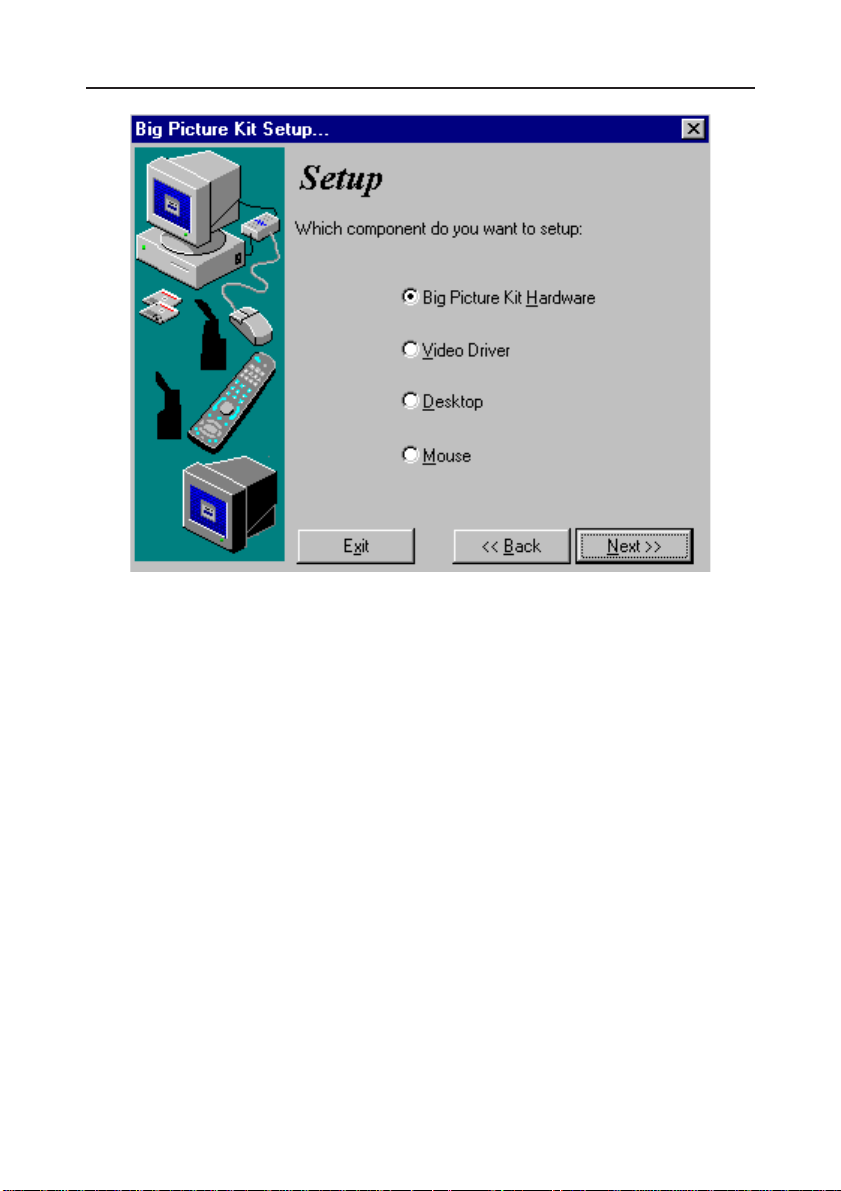
Then if you click on the third button (Desktop) and then click Next,
you are shown how to set up user profiles. This lets you decide when
you boot up whether you want your PC to boot to its normal mode or
to the mode you use for the Big Picture System. For example, you
could set a profile for the Big Picture that uses larger fonts (that are
easier to read on your TV). You could also move your desktop icons
away from the edge of the monitor screen so they all show up
properly on your TV screen. If you don't do this some icons might be
partially off the edge of your TV screen.
Finally when you click Mouse and then click Next, you launch the
installer for the Mouse Remote software as described on page 30.
9
Page 10
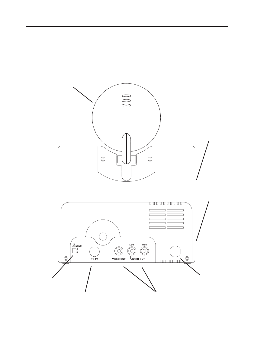
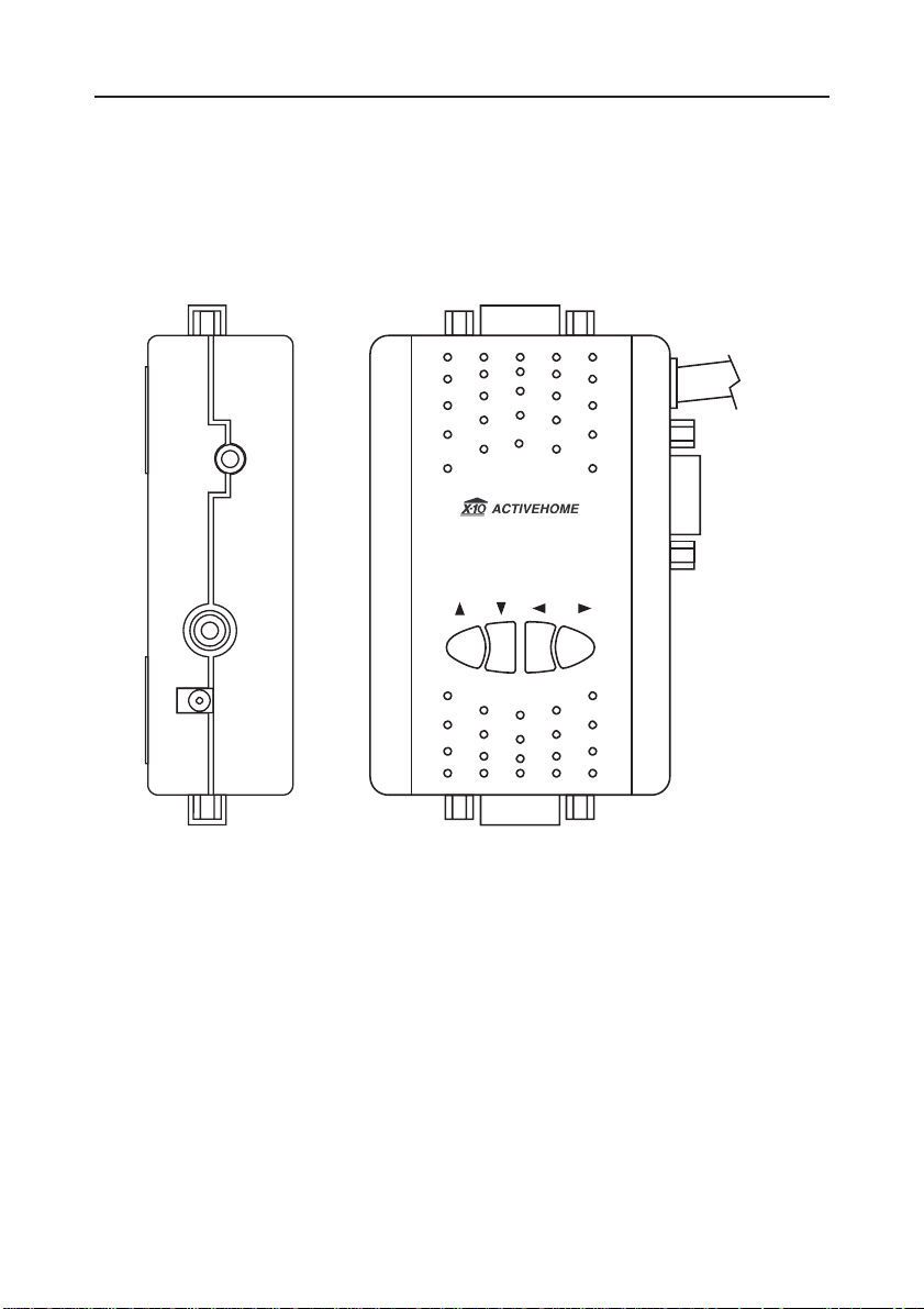
CONTROLS AND CONNECTIONS
V
IDEO SENDER TRANSMITTER
2.4 GHz
Video
Antenna
310 MHz
Antenna for
Mouse Remote
Features
(VT24A)
Channel
Switch
Power On-Off
Switch
DC OUT Jack
(to VA23A)
Mouse
Extender Jack
(to VA23A)
Power Cord
A/V Input
Jacks
10
Page 11
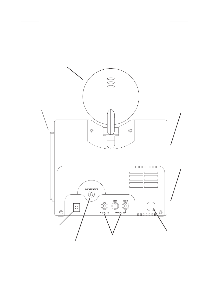
V
IDEO SENDER RECEIVER
2.4 GHz
Video
Antenna
(VR20A)
Channel
Switch
Power On-Off
Switch
TV Channel
Switch
TV Output
Connector
Power Cord
A/V Output
Jacks
11
Page 12
VGA-TO-V
IDEO CONVERTER
MOUSE EXTENDER
(VA23A)
To PC's PS/2
To mouse
or serial port
DC IN
VIDEO OUT
V PAN
H PAN
Use the supplied adapters if you are using a PS/2 mouse and
connecting to a PS/2 port. Note: If you connect a PS/2 Mouse to the
VA23A (using the supplied PS/2-to-serial adapter) you MUST connect
the VA23A to a PS/2 port (using the supplied serial-to-PS/2 adapter).
You cannot connect a PS/2 mouse to the VA23A and then connect
the VA23A to a serial port, or vice versa.
Attach the VA23A to the side of your PC using the supplied Velcro.
™
Use the buttons on the front of the VA23A to adjust the horizontal and
vertical position of the picture displayed on your TV.
12
Page 13
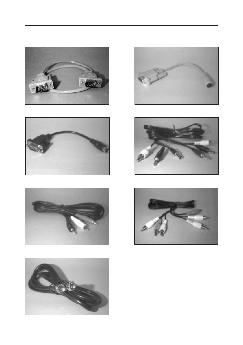
C
ABLES
1 Monitor cable
3 Serial to PS/2 cable (Male)
5 Audio cable
2 PS/2 to Serial cable
(Female)
4 Power/Video/Mouse cable
6 A/V cable
7 Coaxial F connector cable
13
Page 14
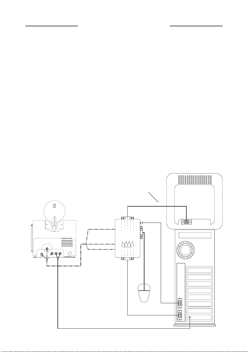
CONNECTING UP
HOOKING UP THE VGA-TO-VIDEO CONVERTER
(WITH A SERIAL MOUSE)
1. Disconnect the computer end of your monitor cable and connect it
to the Monitor OUT socket on the VA23A, leaving the other end
of the cable connected to your monitor.
2. Connect the VGA output from your computer to the VGA IN
socket on the VA23A, using cable
3. Connect your existing serial mouse to the serial input on the
VA23A.
4. Connect the serial output on the VA23A to the serial mouse port
on your PC.
5. Peel the backing from the attached Velcro
to the side of your computer.
VT24A
MOUSE
EXTENDER
DC
VIDEO IN
AUDIO IN
LEFT RIGHT
MOUSE
EXTENDER
VIDEO OUT
MONITOR OUT
DC IN
VGA IN
1.
Your existing
monitor cable.
MOUSE
OUT
VA23A
V Pan
H Pan
™
and attach the VA23A
COMPUTER
MONITOR
PC
Bulleted numbers
refer to the cables
on page 11.
1
14
MOUSE
SERIAL
VGA
LINE OUT
(SPEAKER OUT)
Page 15
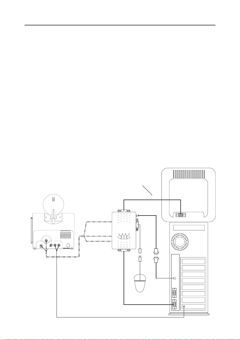
HOOKING UP THE VGA-TO-VIDEO CONVERTER
(WITH A PS/2 MOUSE)
1. Disconnect the computer end of your monitor cable and connect it
to the Monitor OUT socket on the VA23A, leaving the other end
of the cable connected to your monitor.
2. Connect the VGA output from your computer to the VGA IN
socket on the VA23A, using cable
3. Connect your existing PS/2 mouse to the serial input on the
VA23A using the supplied PS/2-to-serial adapter
4. Connect the serial output on the VA23A to the PS/2 mouse port
on your PC using the supplied serial-to-PS/2 adapter
5. Peel the backing from the attached Velcro
to the side of your computer.
VT24A
MOUSE
EXTENDER
DC
VIDEO IN
AUDIO IN
LEFT RIGHT
EXTENDER
VIDEO OUT
MONITOR OUT
MOUSE
DC IN
VGA IN
1.
Your existing
monitor cable.
MOUSE
OUT
VA23A
V Pan
2
H Pan
2.
3.
™
and attach the VA23A
COMPUTER
MONITOR
ADAPTOR
3
PC
Bulleted numbers
refer to the cables
on page 11.
1
15
PS/2
MOUSE
PS/2
SERIAL
VGA
LINE OUT
(SPEAKER OUT)
Page 16
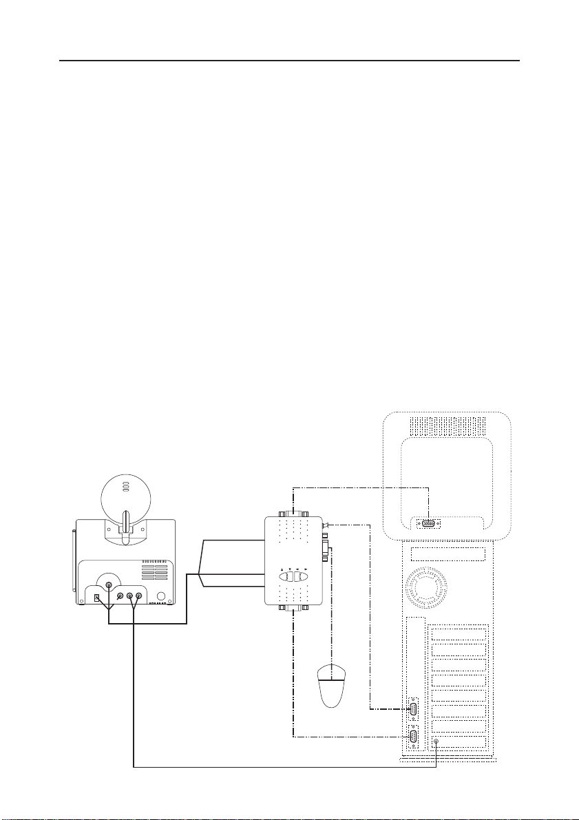
HOOKING UP THE VIDEO SENDER TRANSMITTER
1. Using cable 4 follow these three steps:
A: connect DC OUT on the VT24A to the DC IN on the VA23A.
B: connect mouse extender OUT on the VT24A to mouse extender
IN on the VA23A.
C: connect Video OUT on the VA23A to Video IN on the VT24A.
2. Using cable
sound card to the Audio IN Jacks on the VT24A Transmitter.
3. Plug the Video Sender Transmitter into a convenient 120V outlet.
4. Set the power switch to ON.
5. Fully extend the telescopic antenna.
6. Position the Video Sender Transmitter in a convenient location and
orient the antenna so that the flat side points in the direction of the
room where you will be installing the Video Sender Receiver.
Note: do not place it on top of your monitor as the monitor can
interfere with its operation.
VT24A
MOUSE
EXTENDER
DC
VIDEO IN
4
5 connect the AUDIO out jack from your computer's
COMPUTER
MONITOR
AUDIO IN
LEFT RIGHT
MOUSE
EXTENDER
VIDEO OUT
DC IN
MONITOR OUT
VA23A
V Pan
H Pan
VGA IN
MOUSE
OUT
PC
5
Bulleted numbers
refer to the cables
on page 11.
16
MOUSE
SERIAL
VGA
LINE OUT
(SPEAKER OUT)
Page 17
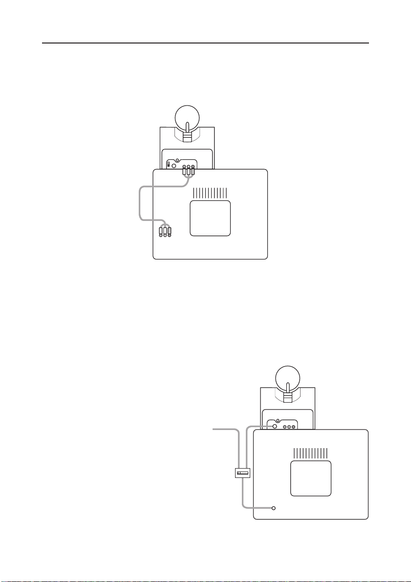
HOOKING UP THE VIDEO SENDER RECEIVER
1. Using cable 6 connect the LINE OUT jacks the Video Sender
Receiver to the Video IN jacks on your TV.
Bulleted numbers
refer to the cables
on page 11.
AUDIO
VIDEO
LR
TV
6
LR
VIDEO
AUDIO
2. Plug the Video Sender Receiver into a 120 volt wall outlet.
3. Set power switch to ON.
4. Position the Video Sender Receiver in a convenient location and
orient the antenna so that the flat side points in the direction of the
room where you set up the Video Sender Transmitter.
IF
YOUR
TV
DOES NOT HAVE
A/V L
INE IN CONNECTORS
You can use the supplied coaxial
F connector cable
the TV OUT socket on the Video
7 to connect
TO TV ANTENNA
7
TO TV
Sender to the Antenna input on
your TV. If you already have an
antenna connected to your TV,
you will need to use a standard
TV antenna splitter.
12
TV
UHF/VHF
ANTENNA
Set your TV and the TV Channel
switch on the Video Sender to the
same channel (3 or 4).
TV
17
Page 18
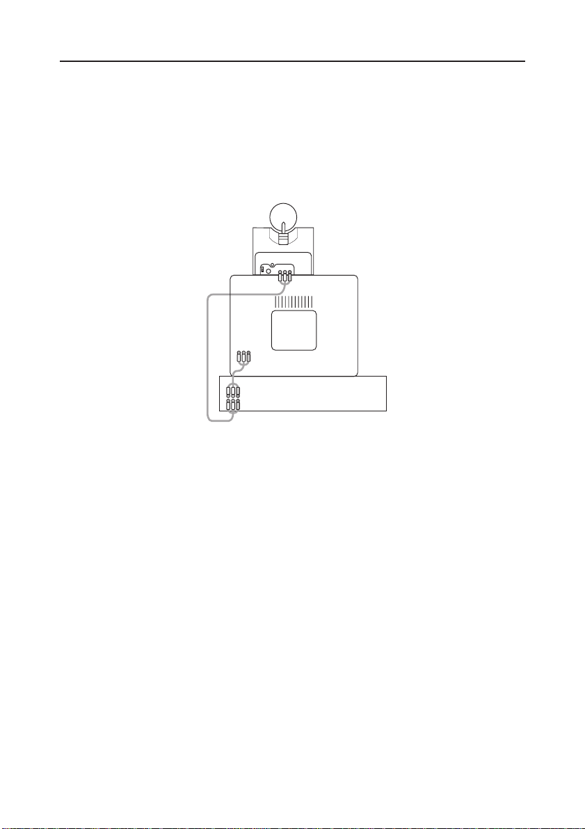
IF
YOUR
A/V
TV IS
DEVICE
ALREADY HOOKED UP TO A
DSS R
ECEIVER OR OTHER
If your DSS Receiver or other A/V component is connected to the TV
using A/V cables, you can connect the Video Sender Receiver to the
free LINE IN jacks on the component. If there are no LINE IN jacks,
you will need to use a TV antenna splitter as described earlier.
AUDIO
VIDEO
LR
TV
AUDIO
VIDEO L R
OUT
IN
DSS
18
Page 19
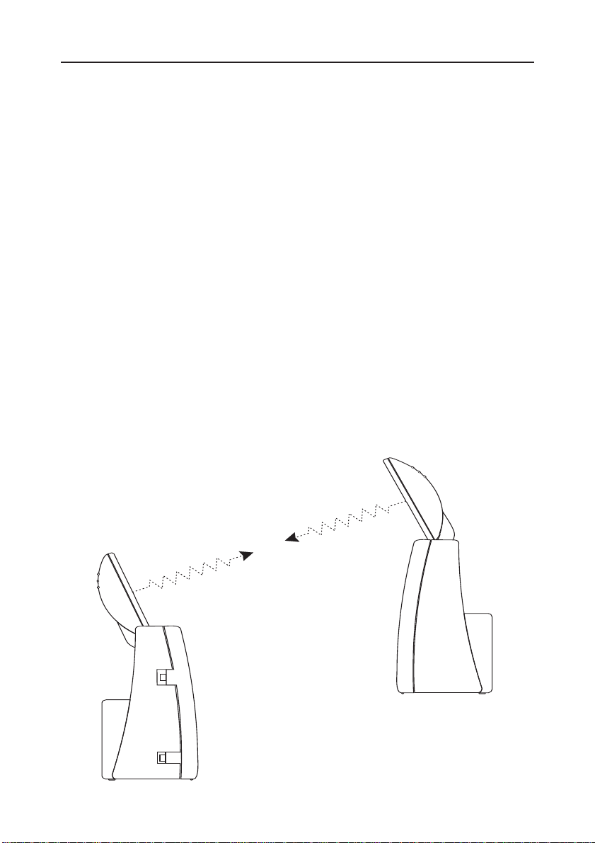
FINE TUNING YOUR VIDEO SENDER
The Wireless Video Sender usually works best with the flat faces of
the antennas on the Transmitter and Receiver unit facing each other
(see diagram below). Sometimes, however, reflections and other
effects in the home may affect the signal so that some adjustment of
either the Transmitter or Receiver antenna may be necessary to get
the best the signal.
If you are not getting any signal at all: Check that the CHANNEL
slide switch (labeled 1 to 4) on both Video Sender units is set to the
same number. If you are using coaxial TV connections from the Video
Sender Receiver, check that the TV is connected to it is tuned to the
same channel as the TV Channel switch on the Video Sender (3 or 4).
IF
THE SIGNAL IS POOR, OR THERE IS INTERFERENCE
Try changing the channel on both Video Sender units. Do this by
adjusting the CHANNEL slide switch on the side of each unit to any
position from 1-4. Make sure both units are set to the same channel.
19
Page 20

RESOLUTION, REFRESH RATE, AND PICTURE ADJUSTMENT
Once you have the VA23A connected to your computer and to the
VT24A transmitter, and the VA20A connected to your TV you will be
able to see the picture from your PC on your TV screen. Note
however that the VA23A only works at 640 x 480 resolution, and a
refresh rate of 60 Hz. If you normally use your computer at a higher
resolution you will need to change this to use the VK25A system.
To do this (for Windows 95) right-click on our desktop and select
properties. Then select settings, choose 640 x 480 and click OK. If a
refresh rate setting is offered, make sure it is set for 60 Hz. (Note: an
updated driver might be available for your video card from the video
card manufacturer's WEB site). It might be necessar y to reboot your
computer after changing this setting.
For Windows 3.x
1. Select the Windows Setup icon in the Program Manager.
2. Choose Change System Settings from the Options menu.
3. Select the 640 x 480 driver for the installed video card from the
Display pull-down box. Select 60 Hz if available (see above).
4. Select OK to confirm the setting change. At this point Windows
will locate the driver (either in the system or on a floppy disk
provided with the video card) and then re-start.
Note: if you can't find the driver for your video card, or the selected
driver doesn't display a picture on your TV, install the standard
Windows VGA driver which should be resident in the system. (Or
download the latest driver for your video card from its manufacturer's
WEB site).
After you see your PC's picture on your TV screen you can adjust its
position up and down, and left and right by pressing the arrow
buttons on the VA23A VGA-to-Video converter.
20
Page 21

MOUSE REMOTE
INTRODUCTION
PC FUNCTIONS....
The VK25A kit includes a Mouse Remote control (JR20A). The remote
control sends wireless RF signals to the VT24A which connects (via
the VA23A) to the mouse port on your PC. This lets you use the JR20A
remote as a wireless mouse. You use the mouse pad on the front of
the remote to move the cursor around the PC screen, and use the
buttons on the back of the remote as the left and right mouse buttons.
It’s that simple!
This lets you use the Mouse Remote to launch your PC's DVD player
from your armchair and play your favorite DVD movie.
However, to take advantage of the advanced features of the Mouse
Remote, you can install the software that came with it. This lets you
configure the remote’s special function buttons (WEB, DVD, CD, and
Phone). You can configure these buttons to perform special functions
such as launching your DVD player from a single button, launch your
WEB Browser, check your e-mail, etc.
UNIVERSAL REMOTE....
You can use the Mouse Remote as a Universal Remote, to control
most audio/video products. Control your TV, VCR, Cable Box,
Satellite Receiver, etc. all from the same convenient and easy to use
remote.
HOME AUTOMATION....
The X-10 Mouse Remote can also control almost any light or
appliance in your home - even in another room! And it’s easy to
install. Within minutes, you can be using your X-10 Mouse Remote to
dim the lights, start brewing a fresh pot of coffee and play your
favorite movie! (Requires X-10 Transceiver and Modules, sold
separately).
21
Page 22

Here are just some of the things you can do with your X-10 Mouse
Remote...
• Control all the functions of your PC, including your DVD player,
etc.
• Control all your A/V equipment including your TV, VCR, Cable,
etc.
• Control your entire audio/video and lighting setup for the ultimate
Home Theater experience.
• Turn on lights at night to scare away intruders if you hear a noise.
• Start the coffee from your bedroom when you wake up.
• Turn on your electric blanket before the movie ends, so it’s nice
and warm when you go to bed.
Use this section of the manual to become familiar with your Mouse
Remote....
This manual explains how to set up your Mouse Remote to use it with
your PC as a wireless mouse.
Then it shows you how to set it up to control your existing Audio/
Video equipment.
Next, it shows you how you can use it with an X-10 Transceiver
Module and Lamp Module (sold separately) to control electrical
devices in your home.
Finally, the manual shows how you can expand your system with
some of the many additional X-10 products you can purchase.
INSTALLING BATTERIES
2. Fit four AAA
1. Push the tab and
lift off the battery
cover.
alkaline batteries,
taking care to
match the + and marks in the
battery
compartment.
22
Page 23

SETTING UP YOUR MOUSE REMOTE
B
UTTON DESCRIPTIONS
INDICATOR LIGHT
The indicator light flashes when the remote is operating (if the button
has a function in the selected mode).
POWER
Works in the same way as your original remote. Turns All Lights On
in X-10 mode. Programmable in PC mode.
SET UP
Used to set up the remote to control your TV, VCR, Cable, etc.
PC
Press first to access WEB, DVD, PHONE, or CD functions.
X-10
Lets you control X-10 Modules to operate lamps and appliances
around the home.
WEB
Can be configured with the enclosed software to launch your
browser, etc.
DVD
Can be configured with the enclosed software to play disks in your
DVD drive.
PHONE
Can be configured with the enclosed software to launch telephony/
fax applications, etc.
CD
Can be configured with the enclosed software to control the PC’s CD
player.
AUX, TV, CBL, SAT, VCR
Used to select the device you want to control. SAT includes DSS .
23
Page 24

0-9
Used as your original remote and to enter device codes. Can also be
configured to perform PC functions.
UP ARROW
Used for shift when in PC mode.
ENTER
Used to confirm certain entries.
VOLUME +/- (UP/DOWN)
Works like your original remote. Also brightens and dims lamps in
X-10 mode. Works as Line Up/Down in PC mode.
CHANNEL +/- (UP/DOWN)
Works like your original remote. Also works as on and off in X-10
mode. Also works as Page Up/Down in PC mode.
MOUSE PAD
Moves the cursor around the screen.
MOUSE BUTTONS (ON BACK)
Used as left and right (looking from front) mouse buttons.
MUTE
Works the same as your original remote. Also turns All Modules Off
in X-10 mode. Also works as Maximize in PC mode.
A-B
Used as a TV/VCR button.
DISP
Used to access on-screen information. Also works as Minimize in PC
mode.
PLAY, REW, F F, STOP
Work the same as on your original VCR remote.
SELECT
Used for menu selections on DSS receivers.
24
Page 25

TIMER
Used to set the Sleep Timer to automatically switch off the TV or X-10
Modules after a preset time.
GUIDE
Displays the main menu on DSS receivers.
REC
Record button. Works the same as your original VCR remote. You
must press the REC button twice to begin recording.
PAUSE
Works the same as your VCR remote.
LAST
Selects the last channel selected.
BUTTON DEAFULTS
The Mouse Remote buttons can be programmed to perform various
functions using the Mouse Remote software, but they are preprogrammed with the following defaults:
When PC mode is selected the keys default to the following:
Key PC mode
Power Close Application
Enter Enter
Play Nudge mouse cursor up
Rew Nudge mouse cursor left
FF Nudge mouse cursor right
Stop Nudge mouse cursor down
Rec Pause 00
11
22
33
Key PC mode
44
55
66
77
88
99
Vol+ Line Up
V ol- Line Down
CH+ Page Up
CH- Page Down
Mute Minimize
A.B Disp Maximize
25
Page 26

Cont: When PC mode is selected the keys default to the following:
Key below + Shift
01 Home
2 Up Arrow
3 Page Up
4 Left Arrow
56 Right Arrow
7 End
Key below + Shift
8 Down Arrow
9 Page Down
Vol+ Line Up
V ol- Line Down
CH+ Page Up
CH- Page Down
Mute Minimize
A.B Disp Maximize
When WEB mode is selected the keys default to the following:
Key WEB mode
WEB Default Browser
Power Enter Play Rew FF Stop Rec Pause 0 www .x10.com
1 www .pc.orcaweb.com
23456789Vol+ Line Up
V ol- Line Down
CH+ Page Up
CH- Page Down
Mute Minimize
A.B Disp Maximize
Key WEB mode
Key below + Shift
01 Home
2 Up Arrow
3 Page Up
4 Left Arrow
56 Right Arrow
7 End
8 Down Arrow
9 Page Down
Vol+ Line Up
V ol- Line Down
CH+ Page Up
CH- Page Down
Mute Minimize
A.B Disp Maximize
26
Page 27

When DVD mode is selected the keys default to the following:
Key DVD mode
Power Enter Play Rew FF Stop Rec Pause 00
11
22
33
44
55
66
77
88
99
Vol+ Line Up
V ol- Line Down
CH+ Page Up
CH- Page Down
Key DVD mode
Mute Minimize
A.B Display Maximize
Key below + Shift
01 Home
2 Up Arrow
3 Page Up
4 Left Arrow
56 Right Arrow
7 End
8 Down Arrow
9 Page Down
Vol+ Line Up
V ol- Line Down
CH+ Page Up
CH- Page Down
Mute Minimize
A.B Disp Maximize
When CD mode is selected the keys default to the following:
Key CD mode
Power Enter Play Play CD
Rew Previous Track
FF Next Track
Stop Stop CD
Rec Pause Pause CD
0 CD Track 10
1 CD Track 1
2 CD Track 2
3 CD Track 3
4 CD Track 4
Key CD mode
5 CD Track 5
6 CD Track 6
7 CD Track 7
8 CD Track 8
9 CD Track 9
Vol+ Master Vol+
Vol- Master VolCH+ Next Track
CH- Previous Track
Mute Master Mute
A.B Disp Maximize
27
Page 28

Cont: When CD mode is selected the keys default to the following:
Key below + Shift
0 CD Track 20
1 CD Track 1 1
2 CD Track 12
3 CD Track 13
4 CD Track 14
5 CD Track 15
6 CD Track 16
7 CD Track 17
Key below + Shift
8 CD Track 18
9 CD Track 19
Vol+ Master Vol+
Vol- Master VolCH+ Next Track
CH- Previous Track
Mute Master Mute
A.B F1
Disp -
When PHONE mode is selected the keys default to the following:
Key PHONE mode
PHONEDefault Dialer
Power Enter Play Rew FF Stop Rec Pause 00
11
22
33
44
55
66
77
88
99
Vol+ Line Up
V ol- Line Down
CH+ Page Up
CH- Page Down
Mute Minimize
A.B Disp Maximize
Key PHONE mode
Key below + Shift
00
1 Home
2 Up Arrow
3 Page Up
4 Left Arrow
56 Right Arrow
7 End
8 Down Arrow
9 Page Down
Vol+ Line Up
V ol- Line Down
CH+ Page Up
CH- Page Down
Mute Minimize
A.B Disp Maximize
28
Page 29

MOUSE OPERATION
The Mouse Remote sends wireless RF signals (from up to 100 ft.
away) to the receiver which built-in to the VT24A Video Sender.
These signals are sent to the VGA to video converter (VA23A) which
passes them on to your PC's mouse port (see diagram on page 10).
To install the Mouse Receiver:
First shut down and turn off your PC. Unplug your mouse and connect
the Mouse OUT on the VA23A to your PC’s serial mouse port (use the
enclosed adapter if you have a PS/2 port). Plug your existing serial
mouse into the socket on the VA23A (use the enclosed adapter if you
have a PS/2 mouse). Turn on your PC.
Note: you can only connect a serial mouse to the VA23A if you
connect its output to your serial port, or connect a PS/2 mouse to the
VA23A if you connect its output to a PS/2 port.
IMPORTANT: You cannot connect the Mouse Output on the VA23A
to a PS/2 port while the PC is turned on. If you try this, your PC will
not recognize your mouse. You can attach the output to a serial port
while the PC is turned on but you will then need to re-boot your
computer.
Now you can use the JR20A Mouse Remote as a wireless mouse. You
use the mouse pad on the front of the remote to move the cursor
around the PC screen, and use the buttons on the back of the remote
as the left and right mouse buttons. It’s that simple!
Mouse pad
Left mouse button
(on back)
Right mouse button
(on back)
29
Page 30

You can, at any time, still use your existing mouse, which always
overrides the Mouse Remote.
Using the Mouse Remote to move the cursor around the screen and
open and close applications is very easy to do and allows you, for
example, to give PC presentations from across the room. However, to
take advantage of the advanced features of the Mouse Remote, you
can install the software that came with it. This lets you configure the
remote’s special function buttons such as PC, WEB, DVD, PHONE,
CD, etc. You can configure these buttons to perform special functions
such as launching your WEB Browser, for example. If you prefer you
can just use the defaults Listed on pages 25 to 27.
MOUSE SOFTWARE INSTALLATION
Installation for Windows 3.x
Insert the Setup Disk or CD into your Floppy or CD drive. Launch File
Manager and click on the drive letter for your Floppy or CD drive
and double-click on Setup.exe. Follow the on-screen prompts to install
the Mouse Remote software (see pages 8 and 9 also). After the
installation is complete you will be given the opportunity to read the
README file. Remember to re-boot your computer after installing the
software.
Installation for Windows 95.
Insert Setup Floppy or CD into your Floppy or CD drive. Use Explorer
to open your Floppy or CD drive and double-click on Setup.exe.
Follow the on-screen prompts to install the mouse software (see pages
8 and 9 also). After the installation is complete you will be given the
opportunity to read the README file. Remember to re-boot your
computer after installing the software. (Note: Windows 95 can
support multiple mice).
Configuration
Windows 3.x: click on the “RF Remote Mouse” icon in the control
panel or click on the minimized mouse icon on the desktop and select
the Configure option from the menu, to bring up a picture of the
Remote.
30
Page 31

Windows 95: click the remote mouse tray icon and select the
“Configure” option from the menu, to bring up a picture of the Mouse
Remote. Note: if the tray icon is not present, this indicates that the
X-10 driver has not been loaded properly, t ry rebooting or
reinstalling the driver.
When the Mouse Remote picture is displayed, moving the cursor
around the screen causes programmable buttons or buttons with
additional help (setup/X-10/TV/CBL/SAT/VCR) to illuminate. Doubleclicking on these buttons will allow them to be programmed or show
additional help. Right-clicking on these buttons will display a pop-up
menu offering additional options.
When you double-click on a button the window shown above is
displayed.
This window lets you configure the button for what you want it to do.
There are 6 different things that you can program a button to do.
These are:
Launch, WWW, Multimedia, Edit, System, & Messages.
31
Page 32

Launch lets you launch any application you choose from the button.
For example: To set up button number 1 to launch your word
processor:
Click on the Mouse Remote icon (on the desktop for Windows 3.x or
in the taskbar for Windows 95) and then click on Configure.
When you see the picture of the Mouse Remote, click on the PC key
and then double-click on the number 1 button.
When you see the picture on the previous page, click Launch.
Clicking on the Launch button on the screen shown on the previous
page displays a window similar to the one below.
The actual window you see depends on what button you clicked and
will be different for Launch, WWW, Multimedia, Edit, System, and
Messages. In this case you clicked on Launch so you will see the
window above. Next click in the File name box and then type in the
path and name for your word processor, or browse to find its
location. Click OK to exit the above window and then again to exit
the window on the previous page . Then close the picture of the
Mouse Remote. Now any time you press PC followed by 1 on the
Mouse Remote, you will launch your word processor.
WWW lets you go straight to whatever URL you designate (after
launching your browser). When you click on WWW you will see a
window with a dialog box into which you type the WEB address that
you want the button to take you to.
Multimedia lets you control your PC's CD or DVD player, etc. from
the button. For example to set up a DVD player: On the Configuration
picture for the Mouse Remote, first click on PC, then click on DVD
then double click on Play.
32
Page 33

When you see the screen on page 29, click on Multimedia. Select
DVD Player for the media device and Play for the function. Repeat the
above steps for Stop, FF, REW, Pause, etc.
Edit lets you set up any key to perform tasks such as Page Up, Page
Down, Tab, Home, Type etc. Type allows to you assign text to a
button so that it will be “typed” into any box you place the cursor
over. For example you could assign a password to any button and
then “type” it into a dialog box with the press of a button when you
launch Compuserv e
®
or America Online,® etc.
System lets you set up any button to maximize, minimize, or resize
windows, close applications, shut down Windows,
®
select the
Windows 95 Start button, etc.
Messages This is an advanced feature that will primarily be used by
programmers. It allows application specific information to be directed
to the associated Windows application. Refer to the on-line help for
more information.
Virtual Keyboard
You can set up any key to launch your e-mail application, word
processor, notepad, etc. you can then launch a virtual keyboard. This
lets you move the cursor around the screen and press buttons on the
virtual keyboard to type text from the Mouse Remote.
33
Page 34

To assign the vir tual keyboard to the A-B button for example:
Select Configure, click on PC, double-click on A-B and select System.
Then select Virtual Keyboard for the function.
Then to use the Virtual keyboard: launch your word processor, e-mail,
etc. then press PC followed by A-B on the Mouse Remote. The picture
on the previous page appears on top of your word processor. Move
the cursor over each key and click the left mouse button on the back
of the Mouse Remote (looking from the front) to press the virtual key.
When you’ve finished "typing" press Enter on the Virtual Keyboard to
enter the text into your word processor (or whatever other application
is on the screen behind the Virtual Keyboard.
Note that the mouse pad and the buttons on the back of the remote
are always active, no matter what mode the remote is in (PC, TV,
VCR, etc.). Note however that the special function buttons (WEB,
PHONE, CD, DVD) are only active after the PC button has been
pressed. Note also that the mouse cursor will move faster as you
press harder on the mouse pad. It actually has three distinct speeds.
Note also that speed, mouse trails, etc. can be set from the Remote
Mouse Properties Sheet in the Control Panel.
Normally you will configure the Mouse Remote’s buttons by clicking
the Tray icon (Windows 95) and then clicking Configure. If the tray
icon is NOT visible in the system tray (because you closed it) Select
Start, Programs, Remote, then Remote Mouse Buttons, to again show
the Remote Mouse tray icon. Click the tray icon then click Configure.
Alternatively: If the tray icon is NOT visible a Configure button will be
available in the properties sheet (in the Control Panel) allowing you
to configure the Mouse Remote Buttons from there. If the tray icon IS
visible in the system tray there is no Configure button in the Properties
Sheet, so the Mouse Remote Buttons can be configured by clicking on
the tray icon and then selecting Configure.
There is extensive on-line help available for the Mouse Remote
software, so it is suggested that you refer to this help for more details.
Note also that information on what each button does is available
with the right-click of the mouse.
34
Page 35

TYPICAL APPLICATION SCENARIO
Here’s a typical scenario that gives you an idea of what you can do
with the power of the Mouse Remote:
Program 10 WEB sites into the numeric keys (e.g. 1 for
www.x10.com, 2 for www.orcaweb.com...), then sit back in your
armchair and press the PC key followed by the WEB key to launch
your WEB browser. Then position the cursor over the URL field and
press 1, 2, etc. to go directly to the address and read the latest
information from each WEB site. Then using the channel up and
down keys and volume up and down keys as scroll functions page
through the site, while listening to a CD that you started playing
earlier. After a while, skip back to track 7 on the CD by pressing CD
followed by 7. Then return to WEB browsing mode by pressing the
WEB key. Later still, as it starts to get dark, press the X-10 key and
turn on the living room lights.* Then press the CD key and press
pause while you answer the phone. Press the Power button to close
your WEB browser and then press the PHONE button that you
previously configured to launch Pointcast.
you read the latest issue of Wired
.™
To configure the above:
™
Sit back and relax while
magazine on-line.
Click the tray icon and select Configure. Click the PC button then
double-click the WEB button, then click Launch. Type in the name of
your browser, or Browse to find its location. Click OK twice.
Click the PC button, then double-click button 1. Click WWW, then
type the desired WEB address. Click OK. Repeat the process for each
address you want to program for each numeric button.
Click PC, then CD, then double-click Play. Click Multimedia. Select
your media device and function (Play). Repeat the process for Stop,
Pause, FF, REW, MUTE, numeric keys, etc.
Get the idea?
* Required X-10 Transceiver and Modules (sold separately).
35
Page 36

SETTING UP FOR TV, VCR, C ABLE BOX, CD, AND
SATELLITE RECEIVER
1. Turn on the device
you want to control
(TV, VCR, cable
box, satellite
receiver etc.).
3. Press and release
the mode button
that matches the
device you want
to control. The LED
blinks once. Use
AUX for CD
equipment.
5. Point the remote at
the device and
press the POWER
button. Your device
should turn off.
Notes:
2. Press and hold
SETUP until the
LED indicator
lights steadily.
Release the
SETUP button.
4. Enter the 3 digit
Code from the
Library Code
Tables. The LED
turns off after
the last digit
entered.
6. Turn your
device on and
press
CHANNEL+. If
the device
responds,
setup is
complete.
For CD players use the AUX button. For Laser Disks use the VCR
button.
If your TV/VCR/Cable Box/Satellite Receiver does not respond, try the
other codes for your brand. If it still doesn’t respond, try the Code
Search method on page 52.
If the LED blinked rapidly when you entered the code, you may have
entered an invalid code. Recheck the code in the code list and try
again.
If some buttons do not operate your equipment, try one of the other
codes for your brand.
36
Page 37

TV CODES
ABEX .........................................................................................................................185
ACME........................................................................................................................ 003
ADA ..........................................................................................................................016
ADC ..................................................................................................................012, 096
ADMIRAL............................................................................................................014, 186
ADVENTURA ..............................................................................................................187
AIKO ......................................................................................................................... 029
ALLERON ...................................................................................................................059
AMTRON ................................................................................................................... 051
AKAI..........................................................................................................................015
AMSTRAD ..................................................................................................................202
ANAM NATIONAL............................................................. 016, 051, 055, 205, 206, 207
AOC......................................................................... 017, 018, 020, 022, 188, 189, 208
AUDIOVOX ................................................................................................................ 051
.......................................................................................................................................
BELCOR ..................................................................................................................... 017
BELL & HOWELL..........................................................................................014, 062, 096
BRADFORD.................................................................................................................051
BROKWOOD .............................................................................................................017
.......................................................................................................................................
CANDLE.............................................................................................017, 021, 022, 187
CAPEHART ................................................................................................................. 188
CELEBRITY ..................................................................................................................015
CENTURION .............................................................................................................. 022
CETRONIC ................................................................................................................. 055
CITIZEN .................................... 017, 021, 022, 029, 051, 055, 084, 118, 184, 187, 190
CLAIRTONE ................................................................................................................ 189
CLASSIC .................................................................................................................... 055
COLORTYME ......................................................................................017, 022, 023, 213
CONCERTO .......................................................................................................017, 022
CONTEC/CONY....................................................... 024, 025, 026, 027, 051, 055, 189
CRAIG ...............................................................................................................051, 055
CROWN ....................................................................................................051, 055, 184
CURTIS MATHES ................................................ 013, 017, 022, 028, 062, 084, 118, 184
CXC...................................................................................................................051, 055
.......................................................................................................................................
DAEWOO................................. 017, 018, 022, 029, 030, 031, 055, 098, 139, 140, 184
DAYTRON .................................................................................................. 017, 022, 184
DIMENSIA..................................................................................................................013
DUMONT...........................................................................................................017, 164
DYNASTY...................................................................................................................055
37
Page 38

DYNATECH ................................................................................................................191
.......................................................................................................................................
ELECTROBAND................................................................................................... 015, 189
ELECTROHOME ......................................................................... 016, 017, 022, 034, 035
EMERSON ........................ 017, 022, 025, 027, 036, 037, 038, 039, 040, 043, 044, 045
........................................ 046, 047, 048, 049, 050, 051, 052, 053, 054, 055, 056, 057
........................................ 058, 059, 060, 062, 136, 137, 176, 184, 189, 190, 192, 210
ENVISION..........................................................................................................017, 022
.......................................................................................................................................
FISHER ...............................................................................................062, 063, 064, 193
FUJITSO .....................................................................................................................059
FUNAI .......................................................................................................051, 055, 059
FUTURETEC ........................................................................................................051, 055
.......................................................................................................................................
GE.... 013, 016, 017, 022, 035, 065, 067, 068, 100, 176, 177, 178, 179, 180, 181, 194
GIBRALTER .......................................................................................................... 017, 164
GOLDSTAR................................ 017, 018, 022, 025, 069, 070, 071, 168, 169, 184, 185
GRUNDY ................................................................................................... 051, 059, 184
.......................................................................................................................................
HALLMARK .........................................................................................................017, 022
HARVARD ...................................................................................................................051
HITACHI .................... 017, 022, 024, 025, 026, 072, 073, 074, 100, 150, 151, 152, 153
........................................ 154, 155, 156, 157, 158, 159, 160, 161, 163, 192, 211, 212
.......................................................................................................................................
IMA ...........................................................................................................................051
INFINITY ....................................................................................................................075
.......................................................................................................................................
JANEIL .......................................................................................................................187
JBL .............................................................................................................................075
JCB ............................................................................................................................015
JC PENNY ......................................... 013, 017, 018, 021, 022, 035, 065, 067, 071, 076
................................................................ 077, 084, 100, 118, 141, 184, 185, 194, 214
JENSEN .............................................................................................................017, 022
JVC................................... 024, 025, 026, 067, 073, 078, 079, 080, 102, 171, 172, 195
.......................................................................................................................................
KAWASHO................................................................................................. 015, 017, 022
KAYPANI .................................................................................................................... 188
KEC ...........................................................................................................................055
KENWOOD .......................................................................................................017, 022
KLOSS NOVABEAM ............................................................................081, 082, 187, 196
KTV................................................................................... 051, 055, 083, 184, 189, 190
.......................................................................................................................................
LODGENET ................................................................................................................096
38
Page 39

LOEWE ......................................................................................................................075
LOGIK........................................................................................................................096
LUXMAN ............................................................................................................017, 022
LXI .................................................................................... 013, 022, 062, 075, 084, 194
MEGATRON.......................................................................................................022, 072
MAGNAVOX............................................. 017, 021, 022, 075, 081, 082, 087, 088, 089
........................................................ 090, 101, 102, 143, 144, 145, 146, 147, 196, 197
MAJESTIC...................................................................................................................096
MARANTS..................................................................................................................075
MARANTZ..........................................................................................017, 022, 075, 091
MA TSUI...................................................................................................................... 075
MEI............................................................................................................................ 189
MEMOREX ................................................................................ 014, 022, 062, 095, 096
MGA ................................................ 017, 018, 022, 034, 035, 059, 064, 092, 093, 095
MIDLAND.................................................................................. 067, 164, 184, 185, 194
MINUTZ .....................................................................................................................065
MITSUBISHI ....................................................................... 017, 018, 022, 034, 035, 059
................................................................................ 064, 092, 093, 094, 095, 102, 138
MONTGOMERY WARD...............................................................................................096
MOTOROLA .......................................................................................................016, 186
MTC ......................................................................... 017, 018, 022, 084, 118, 189, 191
MULTITECH.........................................................................................................051, 191
MULTIVISION..............................................................................................................097
.......................................................................................................................................
NAD ..........................................................................................................022, 084, 198
NEC ................................................................. 016, 017, 018, 022, 098, 102, 108, 213
NIKEI .........................................................................................................................055
NIKKO...............................................................................................................022, 029
NTC .......................................................................................................................... 029
.......................................................................................................................................
ONKING ................................................................................................................... 055
ONW A ..............................................................................................................051, 055
OPTIMUS ...................................................................................................................198
OPTONICA ........................................................................................................108, 186
ORION ...................................................................................................................... 048
.......................................................................................................................................
PANASONIC......................................................................................016, 067, 075, 183
PHILCO ............. 016, 017, 018, 021, 022, 025, 075, 081, 082, 087, 088, 090, 196, 197
PHILIPS ............................................................. 016, 017, 019, 021, 022, 025, 075, 081,
........................................................................ 082, 087, 088, 089, 099, 100, 101, 102
PILOT .................................................................................................................017, 184
PIONEER ................................................................... 017, 022, 103, 104, 105, 192, 198
PORTLAND ................................................................................ 017, 018, 022, 029, 184
39
Page 40

PRICE CLUB ................................................................................................................118
PRISM ........................................................................................................................067
PROSCAN..........................................................................................................013, 194
PROTON........................................................................... 017, 022, 025, 106, 188, 199
PULSAR ......................................................................................................................164
PULSER.......................................................................................................................017
.......................................................................................................................................
QUASAR............................................................................................016, 067, 083, 107
.......................................................................................................................................
RADIO SHACK/REALISTIC .. 013, 017, 022, 024, 025, 051, 054, 055, 062, 108, 184, 185
RCA........................................................... 013, 016, 017, 018, 020, 022, 109, 111,112
................................................................ 113, 114, 115, 116, 142, 192, 194, 200, 201
RHAPSODY ................................................................................................................189
RUNCO .....................................................................................................................164
.......................................................................................................................................
SAMPO..................................................................................... 017, 022, 184, 185, 188
SAMSUNG........ 017, 018, 022, 024, 025, 028, 084, 117, 118, 119, 184, 185, 214, 217
SAMSUX .................................................................................................................... 184
SANYO ............................................................ 017, 062, 063, 093, 120, 121, 182, 193
SCOTCH....................................................................................................................022
SCOTT .............................................................. 017, 022, 025, 037, 048, 051, 055, 059
SEARS............................................................... 013, 017, 022, 026, 059, 062, 063, 064
................................................................ 079, 084, 118, 122, 123, 193, 194, 202, 210
SHARP .............................................................................. 017, 022, 025, 108, 124, 125
................................................................................................ 126, 127, 135, 184, 186
SHOGUN ..................................................................................................................017
SIGNATURE................................................................................................014, 096, 128
SIMPSON ..................................................................................................................021
SONIC.......................................................................................................................189
SONY................................................................................................................015, 019
SOUNDESIGN .................................................................. 017, 021, 022, 051, 055, 059
SQUAREVIEW ............................................................................................................202
SSS............................................................................................................ 017, 051, 055
ST ARLITE..................................................................................................................... 051
SUPRE-MACY..............................................................................................................187
SUPREME ...................................................................................................................015
SYLVANIA . 017, 021, 022, 075, 081, 082, 087, 088, 089, 090, 101, 129, 174, 196, 197
SYMPHONIC..............................................................................................046, 051, 202
.......................................................................................................................................
T ANDY.......................................................................................................................186
T ATUNG............................................................................................................. 016, 191
TECHNICS .................................................................................................................067
TECHWOOD..............................................................................................017, 022, 067
40
Page 41

TEKNIKA ................................................... 017, 018, 021, 022, 025, 026, 029, 051, 055
................................................................ 059, 084, 089, 095, 096, 118, 183, 184, 187
TELECAPTION.............................................................................................................130
TELERENT ................................................................................................................... 096
TERA..........................................................................................................................199
TMK...................................................................................................................017, 022
TOSHIBA................................................... 062, 084, 102, 118, 122, 130, 131, 173, 214
TOTEVISION .............................................................................................................. 184
.......................................................................................................................................
UNIVERSAL ........................................................................................................065, 100
.......................................................................................................................................
VICTOR ..............................................................................................................079, 195
VIDTECH ....................................................................................................017, 018, 022
VIKING ......................................................................................................................187
.......................................................................................................................................
W ARDS..................................... 013, 014, 017, 018, 022, 037, 046, 059, 065, 075, 081
................................................ 082, 087, 088, 089, 096, 100, 101, 108, 132, 133, 197
.......................................................................................................................................
YAMAHA ................................................................................................... 017, 018, 022
YUPITERU ...................................................................................................................055
.......................................................................................................................................
ZENITH ............................................................................. 096, 134, 164, 165, 166, 167
VCR CODES
ADMIRAL....................................................................................................................014
ADVENTURA ..............................................................................................................039
AIKO ......................................................................................................................... 040
AIW A ................................................................................................................015, 039
AKAI......................................................... 016, 017, 018, 019, 020, 021, 124, 125, 126
AMERICAN HIGH ....................................................................................................... 034
ASHA ........................................................................................................................ 026
AUDIO DYNAMICS .............................................................................................022, 023
AUDIOVOX ................................................................................................................ 027
.......................................................................................................................................
BELL & HOWELL..........................................................................................................024
BEAUMARK ................................................................................................................ 026
BROKSONIC ......................................................................................................025, 038
.......................................................................................................................................
CALIX.........................................................................................................................027
CANDLE.................................................................... 026, 027, 028, 029, 030, 031, 032
CANON ....................................................................................................034, 035, 127
CAPEHART .........................................................................................................033, 123
CARVER ..................................................................................................................... 075
41
Page 42

CCE...................................................................................................................040, 074
CITIZEN ............................................................ 026, 027, 028, 029, 030, 031, 032, 040
COLORTYME ..............................................................................................................022
COLT .........................................................................................................................074
CRAIG ...............................................................................................026, 027, 036, 074
CURTIS-MATHES ................................................. 013, 015, 022, 026, 029, 031, 034, 035
CYBERNEX .................................................................................................................026
DAEWOO................................................. 028, 030, 032, 038, 039, 040, 041, 123, 143
DAYTRON ..................................................................................................................123
DBX ...................................................................................................................022, 023
DIMENSIA..................................................................................................................013
DYNATECH ........................................................................................................015, 039
ELECTROHOME .................................................................................................. 027, 042
ELECTROPHONIC .......................................................................................................027
EMERSON ................................ 015, 019, 025, 027, 028, 034, 037, 038, 039, 042, 043
................................................ 044, 045, 046, 047, 048, 049, 050, 051, 052, 053, 054
................................................ 055, 056, 057, 058, 059, 060, 078, 118, 126, 129, 130
FISHER .............................................................. 024, 036, 061, 062, 063, 064, 065, 131
FUJI ...................................................................................................................034, 132
FUNAI ...............................................................................................................015, 039
GARRARD ..................................................................................................................039
GE............................................................................ 013, 026, 034, 035, 066, 128, 133
GOLDSTAR................................................................................ 022, 027, 031, 067, 134
GRADIENTE................................................................................................................039
HARLEY DAVIDSON ....................................................................................................039
HARMAN KARDON ............................................................................................022, 081
HARWOOD ...............................................................................................................074
HEADQUARTER .......................................................................................................... 024
HITACHI ............................................................ 015, 068, 069, 070, 120, 124, 133, 135
HI-Q ..........................................................................................................................036
.......................................................................................................................................
INSTANT REPLAY.........................................................................................................034
.......................................................................................................................................
JCL ............................................................................................................................ 034
JC PENNEY ....... 022, 023, 024, 026, 027, 034, 035, 068, 069, 071, 072, 073, 120, 131
JENSEN ..................................................................................................................... 124
JVC............................................................................ 022, 023, 024, 031, 071, 124, 136
KENWOOD .......................................................022, 023, 024, 029, 031, 071, 124, 136
KLH.................................................................................................................... 074, 144
KODAK.............................................................................................................. 027, 034
42
Page 43

LLOYD............................................................................................................... 015, 039
LOGIK....................................................................................................................... 074
LXI ............................................................................................................................ 027
......................................................................................................................................
MAGNAVOX............................................................. 034, 035, 075, 076, 117, 121, 137
MAGNIN.................................................................................................................. 026
MARANTZ................................................. 022, 023, 024, 029, 031, 034, 071, 075, 077
MARTA ...................................................................................................................... 027
MASUSHITA .............................................................................................................. 034
MEI........................................................................................................................... 034
MEMOREX ........................................ 014, 015, 024, 026, 027, 034, 036, 039, 056, 117
MGA ........................................................................................................ 042, 078, 126
MGN TECHNOLOGY ................................................................................................ 026
MIDLAND .................................................................................................................. 066
MINOLTA .................................................................................................. 068, 069, 120
MITSUBISHI ....................................................... 042, 068, 069, 078, 079, 080, 081, 082
........................................................................ 083, 084, 085, 086, 087, 119, 126, 136
MONTGOMERY WAR D...................................................................................... 014, 088
MOTOROLA ...................................................................................................... 014, 034
MTC ......................................................................................................... 015, 026, 039
MULTITECH................................................................................ 015, 026, 039, 066, 074
......................................................................................................................................
NEC ......................... 022, 023, 024, 029, 031, 071, 077, 089, 090, 091, 092, 124, 136
NIKKO...................................................................................................................... 027
NOBLEX .................................................................................................................... 026
......................................................................................................................................
OLYMPUS.................................................................................................................. 034
OPTIMUS .......................................................................................................... 014, 027
OPTONICA ....................................................................................................... 109, 147
......................................................................................................................................
PANASONIC..................................................................... 034, 035, 122, 138, 139, 140
PENTAX............................................................................. 029, 068, 069, 029, 120, 133
PENTEX RESEARCH .................................................................................................... 031
PHILCO ............................................................................................. 034, 035, 075, 076
PHILIPS .............................................................................................. 034, 075, 109, 137
PILOT ........................................................................................................................ 027
PIONEER ................................................................................... 023, 068, 093, 094, 136
PORTLAND ........................................................................................ 029, 030, 032, 123
PROSCAN................................................................................................................. 013
PROTEC .................................................................................................................... 074
PULSAR ..................................................................................................................... 117
......................................................................................................................................
QUARTER.................................................................................................................. 024
43
Page 44

QUARTZ.................................................................................................................... 024
QUASAR................................................................................................... 034, 035, 138
RCA.................................................. 013, 016, 026, 034, 068, 069, 095, 096, 097, 098
........................................................ 099, 100, 101, 102, 103, 104, 120, 128, 133, 138
RADIOSHACK/REALISTIC ........................................... 014, 015, 024, 026, 027, 034, 035
........................................................................................ 036, 039, 042, 062, 063, 109
RADIX ....................................................................................................................... 027
RANDEX ................................................................................................................... 027
RICOH ...................................................................................................................... 141
RUNCO .................................................................................................................... 117
.......................................................................................................................................
SAMSUNG........................................................................ 018, 026, 028, 046, 066, 125
SANKY ..............................................................................................................014, 117
SANSUI .............................................................................................023, 105, 124, 136
SANYO ..................................................................................................... 024, 026, 036
SCOTT .............................................................. 025, 028, 038, 045, 051, 078, 106, 129
SEARS............................... 024, 027, 034, 036, 061, 062, 063, 064, 068, 069, 120, 131
SHARP ...................................................................... 014, 015, 030, 042, 107, 108, 109
SHINTOM ................................................................................. 017, 069, 074, 111, 145
SHOGUN ..................................................................................................................026
SIGNATURE................................................................................................................015
SINGER..............................................................................................................034, 074
SONY....................................................................................... 017, 111, 112, 132, 141
STS ....................................................................................................................034, 120
SYLVANIA ......................................................... 015, 034, 035, 039, 075, 076, 078, 137
SYMPHONIC......................................................................................................015, 039
.......................................................................................................................................
T ANDY...............................................................................................................015, 024
T ASHIKO....................................................................................................................027
T ATUNG............................................................................................................. 071, 124
TEAC ........................................................................................ 015, 039, 071, 098, 124
TECHNICS .........................................................................................................034, 122
TEKNIKA ........................................................................... 015, 027, 034, 113, 142, 039
TOSHIBA................................................................... 028, 062, 064, 068, 078, 106, 129
TOTEVSION .......................................................................................................026, 027
TMK........................................................................................................... 026, 037, 060
.......................................................................................................................................
UNITECH ...................................................................................................................026
.......................................................................................................................................
VECTOR RESEARCH ............................................................................022, 023, 028, 029
VICTOR ......................................................................................................................023
VIDEO CONCEPTS .................................................................... 022, 023, 028, 029, 126
VIDEOSONIC .............................................................................................................026
44
Page 45

WARDS ..................................................... 014, 015, 026, 027, 028, 034, 036, 039, 042
................................................................ 068, 069, 074, 109, 114, 115, 116, 120, 129
XR-1000 .....................................................................................................034, 039, 074
YAMAHA .......................................................................... 022, 023, 024, 031, 071, 124
ZENITH ..................................................................................... 017, 111, 117, 132, 141
CABLE CODES
ABC.......................................................................... 014, 015, 016, 017, 018, 019, 020
ANTRONIX.........................................................................................................021, 022
ARCHER .............................................................................................021, 022, 023, 024
.......................................................................................................................................
CABLETENNA.............................................................................................................021
CABLEVIEW ............................................................................................................... 021
CENTURY................................................................................................................... 024
CITIZEN ..................................................................................................................... 024
COLOUR VOICE ................................................................................................. 025, 026
COMTRONICS ...................................................................................................027, 028
CONTEC....................................................................................................................029
.......................................................................................................................................
EASTERN ................................................................................................................... 030
.......................................................................................................................................
GARRARD .................................................................................................................. 024
GC ELECTRONICS ......................................................................................................022
GEMINI .............................................................................................................031, 032
GENERAL INSTRUMENT .............................................................................................. 016
.......................................................................................................................................
HAMLIN .............................................................................................033, 034, 035, 048
HITACHI ..................................................................................................................... 016
HYTEX........................................................................................................................015
.......................................................................................................................................
JASCO....................................................................................................................... 024
JERROLD.................................................... 014, 016, 018, 020, 031, 036, 037, 062, 063
.......................................................................................................................................
MAGNAVOX..............................................................................................................038
MEMOREX .................................................................................................................039
MOVIE TIME ...............................................................................................015, 040, 041
.......................................................................................................................................
NSC ..................................................................................................................015, 040
.......................................................................................................................................
OAK .......................................................................................................... 015, 029, 042
.......................................................................................................................................
PANASONIC..............................................................................................013, 061, 064
PARAGON................................................................................................................. 039
45
Page 46

PHILIPS .............................................................. 024, 025, 026, 032, 038, 043, 044, 045
PIONEER............................................................................................................ 046, 047
PULSAR ......................................................................................................................039
.......................................................................................................................................
RADIO SHACK ........................................................................................................... 058
RCA...................................................................................................................013, 060
REALISTIC...................................................................................................................022
REGAL ...............................................................................................................035, 048
REGENCY ..................................................................................................................030
REMBRANDT ..............................................................................................................016
RUNCO .....................................................................................................................039
.......................................................................................................................................
SAMSUNG.........................................................................................................027, 047
SCIENTIFIC A TLANTA ................................................. 019, 049, 050, 051, 065, 066, 067
SIGNAL..............................................................................................................027, 031
SIGNATURE................................................................................................................016
SL MARX ....................................................................................................................027
SPRUCER....................................................................................................................013
STANDARD COMPONENTS ........................................................................................052
STARCOM ..................................................................................................014, 020, 031
ST ARGATE .......................................................................................................... 027, 031
ST ARQUEST................................................................................................................031
.......................................................................................................................................
T ANDY.......................................................................................................................053
TELEVIEW...................................................................................................................027
TEXSCAN...................................................................................................................052
TOCOM.....................................................................................................017, 036, 054
TOSHIBA....................................................................................................................039
TUSA .........................................................................................................................031
TV86..........................................................................................................................040
.......................................................................................................................................
UNIKA .......................................................................................................021, 022, 024
UNITED ARTISTS .........................................................................................................015
UNITED CABLE ...........................................................................................................014
UNIVERSAL ............................................................................... 021, 022, 023, 024, 055
.......................................................................................................................................
VIDEOWAY ................................................................................................................057
VIEWSTAR................................................................................. 028, 038, 040, 053, 056
.......................................................................................................................................
ZENITH ......................................................................................................................039
.......................................................................................................................................
46
Page 47

SA TELLITE CODES
AMPLICA....................................................................................................................028
.......................................................................................................................................
BIRDVIEW .................................................................................................................. 029
.......................................................................................................................................
CHANNEL MASTER.....................................................................................030, 031, 032
CHAPPARAL .......................................................................................013, 014, 033, 034
CHEYENNE................................................................................................................014
.......................................................................................................................................
DRAKE .............................................................................. 015, 016, 037, 038, 039, 040
DX ANTENNA ....................................................................................................035, 036
.......................................................................................................................................
ECHOSTAR .................................................................................................041, 042, 043
.......................................................................................................................................
FUJITSU ..............................................................................................................044, 045
.......................................................................................................................................
GENERAL INSTRUMENTS ................................................... 017, 018, 019, 046, 047, 048
.......................................................................................................................................
JANEIL ....................................................................................................................... 049
JEROLD ...................................................................................................................... 050
.......................................................................................................................................
KENWOOD ...............................................................................................................051
.......................................................................................................................................
LUXOR ....................................................................................................................... 052
.......................................................................................................................................
MACOM STATE .......................................................................................................... 053
.......................................................................................................................................
NORSTAT ...................................................................................................................054
.......................................................................................................................................
REALISTIC...................................................................................................020, 056, 057
.......................................................................................................................................
SCIENTIFIC ATLANTA .................................................................................................. 060
SIERRA I, II, III ...........................................................................................................014
ST AR TRAK ................................................................................................................. 061
STS ................................................................................... 021, 022, 023, 024, 058, 059
SUPER GUIDE .............................................................................................................062
.......................................................................................................................................
TOSHIBA............................................................................................................025, 063
.......................................................................................................................................
UNIDEN.............................................................................................................026, 064
.......................................................................................................................................
VIDEO CIPHER II .........................................................................................................027
47
Page 48

LASER DISC CODES
PIONEER....................................................................................................................093
PROSCAN..................................................................................................................146
RCA...........................................................................................................................146
DSS CODES
ECHOSPHERE.............................................................................................................071
ECHOSTAR .................................................................................................................071
.......................................................................................................................................
DISH NETWORK.........................................................................................................071
.......................................................................................................................................
HUGHES SATELLITE .....................................................................................................075
.......................................................................................................................................
PANASONIC......................................................................................................069, 072
PRIMESTAR .................................................................................................................070
.......................................................................................................................................
RCA...........................................................................................................................065
.......................................................................................................................................
SONY........................................................................................................................066
STAR SIGHT CABLE SERVICES ......................................................................................073
.......................................................................................................................................
TOSHIBA....................................................................................................067, 068, 074
CD CODES
ADC ..........................................................................................................................013
ADCOM ............................................................................................................ 014, 067
AIW A ................................................................................................................015, 016
AKAI..................................................................................................................068, 090
AUDIO ALCHEMY....................................................................................................... 017
AUDIO TECHNICA......................................................................................................018
.......................................................................................................................................
BSR............................................................................................................................ 017
.......................................................................................................................................
CALIFORNIA AUDIO LABS ...........................................................................................069
CAPETRONIC .............................................................................................................022
CARRERA ...................................................................................................................017
CARVER ..................................................................................................... 019, 020, 021
CASIO .......................................................................................................................070
CURTIS MATHES .........................................................................................................070
.......................................................................................................................................
DENON............................................................................................................. 023, 024
.......................................................................................................................................
48
Page 49

EMERSON ................................................................................................. 014, 025, 026
.......................................................................................................................................
FISHER .............................................................................. 020, 027, 028, 029, 030, 071
.......................................................................................................................................
GE............................................................................................................................. 078
GENEXXA ..........................................................................................025, 026, 031, 072
GOLDSTAR.........................................................................................................032, 073
.......................................................................................................................................
HARMON KARDON ................................................................................................... 033
HITACHI ..................................................................................................................... 031
.......................................................................................................................................
INKEL ......................................................................................................................... 0 34
.......................................................................................................................................
JC PENNEY ........................................................................................................ 043, 070
JVC............................................................................................................................ 035
.......................................................................................................................................
KENWOOD ...................................................................... 027, 036, 037, 038, 080, 081
KRELL .........................................................................................................................019
KYOCERA ..................................................................................................................013
.......................................................................................................................................
LUXMAN ................................................................................... 039, 040, 082, 083, 091
LXI .....................................................................................................................025, 070
.......................................................................................................................................
MAGNAVOX......................................................................................................019, 084
MARANTZ..........................................................................................019, 041, 042, 085
MCS ..................................................................................................................043, 070
MGA ......................................................................................................................... 044
MISSION ................................................................................................................... 019
MITSUBISHI ........................................................................................................044, 045
.......................................................................................................................................
NAD ..................................................................................................................074, 092
NAKAMICHI.......................................................................................................046, 047
NEC .......................................................................................................................... 043
NIKKO.......................................................................................................018, 026, 029
NSM.......................................................................................................................... 019
.......................................................................................................................................
ONKYO.....................................................................................................048, 049, 075
OPTIMUS .......................................... 017, 020, 021, 025, 031, 037, 050, 051, 052, 053
.......................................................................................................................................
PANASONIC..............................................................................................069, 086, 093
PHILIPS ...............................................................................................................019, 084
PIONEER ............................................................................................031, 054, 055, 072
49
Page 50

PROTON....................................................................................................................019
.......................................................................................................................................
QUASAR....................................................................................................................069
.......................................................................................................................................
RCA.......................................................................................... 014, 020, 025, 056, 076
RCA Digital Video Disc ................................................................................................ 096
REALISTIC.................................................. 014, 020, 022, 025, 026, 031, 042, 050, 052
ROTEL ........................................................................................................................019
.......................................................................................................................................
SAE ...........................................................................................................................019
SAMSUNG.................................................................................................................094
SANSUI .................................................................................... 019, 025, 057, 076, 087
SANYO .................................................................................... 020, 058, 071, 088, 095
SCOTT .......................................................................................................014, 025, 026
SEARS................................................................................................025, 037, 042, 070
SHARP ...............................................................................................................037, 042
SHERWOOD ......................................................................................034, 042, 051, 059
SHURE .......................................................................................................................043
SONY................................................................................................................060, 061
STS ............................................................................................................................013
SYLVANIA ..................................................................................................................019
SYMPHONIC..............................................................................................................062
.......................................................................................................................................
TEAC ................................................................................ 029, 042, 052, 062, 063, 064
TECHNICS ................................................................................................. 069, 086, 089
THETA DIGITAL ............................................................................................................084
TOSHIBA....................................................................................................................074
.......................................................................................................................................
VECTOR RESEARCH ............................................................................................017, 032
VICTOR ......................................................................................................................035
.......................................................................................................................................
YAMAHA ...........................................................................................018, 065, 066, 077
HOME AUTOMATION CODES
X-10 HOME AUTOMATION (RF) ...................................................................................013
X-10 HOME AUTOMATION (IR543) .............................................................................014
GE HOMEMINDER ......................................................................................................015
50
Page 51

USING AUX TO CONTROL A SECOND TV, VCR, CABLE
BOX OR SATELLITE RECEIVER
The AUX button is normally used to control a CD player, but they can
also be configured to control a second TV, VCR, cable box or satellite
receiver.
1. Turn on the A/V equipment you want to control.
2. Press and hold SETUP until the LED indicator lights steadily.
Release Setup button.
3. Press the AUX button.
4. Press and release the mode button that matches the
equipment you want to control. The LED blinks once.
5. Enter the 3 digit Code from the Library Code Tables. The
LED turns off after the last digit entered.
51
Page 52

6. Point the remote at your A/V equipment and press the
POWER button. Your A/V equipment should turn off.
7. Turn your A/V equipment on and press CHANNEL +. If it
responds, setup is complete.
Notes:
If your A/V equipment does not respond, try the other codes for your
brand. If it still doesn’t respond, try the Code Search method below.
If the LED blinked rapidly when you entered the code, you may have
entered an invalid code. Recheck the code in the code list and try
again.
SEARCHING FOR CODES
1. Turn on the device you want to control.
2. Press and hold SETUP until the LED indicator lights steadily.
Release Setup button.
3. Press the mode button (TV, VCR, etc.) that matches the
equipment code you want to search for. The LED blinks once.
Note: To search for a code stored under AUX, press AUX,
release AUX, then press TV, VCR, etc. The LED blinks once.
(Just press AUX only, for CD codes).
52
Page 53

4. Press CHANNEL + repeatedly* until the device to be
controlled changes channel.
If you go past the code accidentally, just press LAST
repeatedly until the channel changes again.
5. Press and release the ENTER button to complete the setup.
*Note: You may have to press CHANNEL+ many times (50+). If the
device does not have a Channel Up function, use the PLAY button
(VCR only) or the POWER button.
IDENTIFYING CODES FOUND USING THE SEARCH PROCEDURE
1. Press and hold the SETUP until the LED indicator lights
steadily. Release Setup button.
2. Press the mode button that matches the equipment you want
to identify (TV, VCR, etc.). The LED blinks once. Note: To
identify a code stored under AUX, press AUX, release AUX,
then press TV, VCR, etc. The LED blinks once. (Just press AUX
only, for CD codes).
53
Page 54

IDENTIFYING CODES FOUND USING THE SEARCH PROCEDURE
(CONT.)
3. Press and release SETUP. The LED blinks once.
4. To find the first digit, press each number button from 0 to 9
until the LED blinks. The number that caused the LED to blink
is the first digit of the code.
5. Press each number button from 0 to 9 again as above
to find the second digit.
6. Press each number button in turn to find the third digit. When
the third digit has been found, the LED will go out.
54
Page 55

SETTING THE SLEEP TIMER
The Sleep Timer automatically turns off the TV after the time you set.
Press the TV* button, then follow the instructions below to set the
Sleep Timer:
1. Press and hold TIMER until the LED indicator lights steadily.
Release TIMER button.
2. Use the number buttons to enter the sleep time required
(1 to 99 minutes).
3. Press ENTER to confirm the setting.
Note: Make sure you leave the remote pointing at the TV to ensure it
turns off the TV at the time you set.
To cancel a Timer: Press TV, then press Power; or press TV then press
the Timer button (blinks once) and hold the Timer button until the LED
blinks again.
* The Sleep Timer will only work for TVs stored directly under the TV
button. It will not work for TVs stored under the AUX button.
55
Page 56

X-10 HOME AUTOMATION
C
ONTROLLERS AND MODULES
The first thing you need to understand is that there are
two different devices you need to control your home;
Controllers and Modules. Any light or appliance that you
want to control is plugged into a Module and that Module
is then plugged into a standard AC outlet.
Modules receive commands from Controllers. Examples
include the Lamp Module and the Appliance Module.
The Transceiver Module is another example of an
Appliance Module (although it also doubles as a
controller as described below).
Controllers are also plugged into standard wall outlets
and send commands to Modules over your existing
electrical wiring in your house without affecting your
electricity in any way.
The Transceiver Module* works as a controller when it
is used with a remote control such as the one included
with this kit. When the Transceiver Module receives a
command from a remote it sends digital signals over
your existing house wiring to a Module which receives
the signals and executes the command.
The remote uses radio frequency (RF) signals to send
commands to the Transceiver module. RF signals can
go right through walls, so you can use the remote to
control lights or appliances from anywhere in your
home.
*Note: If you own an X-10 Security System, its Base
Receiver acts as a Transceiver so you don't need to
purchase an additional Transceiver to use your
Mouse Remote to control your lights and appliances.
56
Page 57

HOUSE CODES AND UNIT CODES
UNIT CODE
DIAL
Each Module has a specific address
made up of a House Code (red dial on
the face of the Module) and a Unit Code
(black dial on the face of the Module).
The Controller first sends an address
HOUSE CODE
DIAL
and then a command over the AC
wiring. Only the Module with a
matching address will execute the
command. If more than one Module has the same address, both
Modules will execute the command.
Addresses are set on the Module by turning the two dials on the front
of the Module to the desired letter and number (using a small
screwdriver or a coin). The House Code is selected from the letters A
through P, and the Unit Code is selected from the numbers 1 through
16.
INSTALLING X-10 COMPONENTS
T
RANSCEIVER MODULE
The Transceiver Module (sold separately) receives radio frequency
(RF) commands from X-10 remotes to operate a lamp or appliance
plugged into it. The Transceiver Module also passes on commands
over your house wiring to control other X-10 modules. Note that
unlike the Lamp Module you cannot dim and brighten a lamp
connected to the Transceiver Module.
You should locate the Transceiver Module centrally in the home for
maximum range when controlled by a remote.
1. Set the House
Code to ‘A.’
2.Plug a lamp or
appliance into the
Transceiver Module.
57
Page 58

3. Plug the Transceiver Module into a convenient AC outlet.
Fully extend the antenna. Note: The transceiver responds
to Unit Codes 1 and 9.
LAMP MODULE
The Lamp Module (sold separately) may be used to control any
incandescent lamp rated up to 300W. It is not suitable for other types
of lamp such as fluorescent or energy saving lamps, or lamps which
include a dimmer control.
Caution: Do not connect an appliance such as a coffee pot or heater
to the Lamp Module. It may damage the module and/or the
appliance and could cause a fire hazard.
1. Set the House Code to ‘A’ and the Unit Code to ‘2.’
2. Plug a lamp into the Lamp Module.
3. Plug the Lamp Module into a convenient AC outlet.
58
Page 59

CONTROLLING X-10 MODULES WITH THE MOUSE REMOTE
If you have already installed the Transceiver Module, you can control
it and other X-10 modules as follows:
1. Press and release the X-10 button.
2. Use the number buttons to enter the Unit Code number of
the chosen module. (You do not need to enter ‘0’ first for a
single digit number.)
3. Press the appropriate button for the function you require
(see below).
X-10 FUNCTIONS:
On: CHANNEL +
Off: CHANNEL –
Bright: VOLUME +
Dim: VOLUME –
All Lamps On: POWER
All Modules Off: MUTE
Note: You cannot dim or brighten an Appliance Module. If the
module was off and you press Bright or Dim (VOLUME+ or VOLUME-)
this will simply turn the module on.
Tip: After controlling X-10 Modules, press the TV button to return your
remote to TV mode. If you forget that the remote is in X-10 mode, next
time your press Mute, say when the phone rings, instead of muting
your TV, you will turn off all your lights instead!
59
Page 60

TO SET THE X-10 SLEEP TIMER
The X-10 Sleep Timer switches off the chosen modules after the preset
time.
1. Press and release the X-10 button. Note: The X-10 Sleep
Timer will only work under the X-10 button. It will not work
for X-10 codes stored under the AUX button.
2. Press and hold TIMER until the LED indicator lights steadily.
Release the TIMER button.
3. Use the number buttons to enter the module Unit Code for the
module to be turned off (or on).
4. Press the desired function button (e.g. CHANNEL - to turn the
module off after the preset time, or CHANNEL + to turn the
module on after a preset time).
5. Using the number buttons, enter the sleep time required
(1 to 99 minutes).
6. Press ENTER to confirm the setting.
Press X-10, then press the Timer button (blinks once) and
hold the Timer button until the LED blinks again.
Note: To cancel a Timer:
60
Page 61

CHANGING THE X-10 HOUSE CODE:
The Mouse Remote defaults to House Code A, and in most cases you
will not need to change this, unless you are experiencing interference
from a neighboring X-10 system.
1. Press and release the X-10 button.
2. Press and hold SETUP until the LED indicator lights steadily.
Release Setup button.
3. Use the number buttons to enter the number equivalent to the
chosen House Code (1=A, 2=B ..16=P).
4. Press the ENTER button to confirm the House Code. The LED
turns off.
Note: The House Code you choose must match the House Code on
the Transceiver and Modules you are using it with.
61
Page 62

USING AN IR MINI CONTROLLER (IR543)
If you already own an IR Mini Controller (Model IR543), you will
need to change the X-10 Home Automation code in the remote to use
it. The code for standard X-10 RF Home Automation is 013. This
code is used for transmitting RF commands to an X-10 Transceiver.
The code to control the IR Mini Controller is 014. To change the
code:
1. Press and hold SETUP until the LED indicator lights steadily.
Release the SETUP button.
2. Press and release the X-10 button.
3. Enter 014 to control an IR Mini Controller, or 013 for
standard X-10 RF control. The LED turns off after the last
digit entered.
Note: In most cases, you will not need to use an IR Mini Controller to
receive commands from the Mouse Remote - the Transceiver Module
(or any X-10 Security System) does this for you and has the added
advantage of working through walls. It also has the advantage of
letting you control up to 16 X-10 Modules - i.e. with a Transceiver
when you press 1-6-ON you turn on Module number 16. With an
IR543 when you press 1-6-ON you turn on Modules 1 AND 6. The
IR543 can only control 10 Modules (1-9 plus 0=10). You cannot
control the IR Mini Controller and the Transceiver Module at the same
time from the X-10 button, but you can program an IR Mini Controller
under the AUX button.
62
Page 63

EXPANDING YOUR SYSTEM
Power
Adapter
OFF
T
h
e
r
m
o
s
t
a
t
S
e
t
-
B
a
c
k
C
o
n
t
r
o
l
l
e
r
LO M HI
1
9
513
A
I
EM
A
I
EM
•
•
••
1
9
513
•
•
••
CONTROLLED
The modules illustrated below represent just a few of the wide range
of X-10 compatible modules you can choose from to expand your
Home Automation system. They are available from electrical outlets,
department stores, and mail order catalogs.
X-10 Home Automation products also integrate with X-10 security
systems, so you can use the Mouse Remote to control the same lights
that flash when the security system is tripped.
Check out our WEB Site at: http://www.x10.com
for more information on these and many other X-10 products.
The Dual Floodlight Motion Detector, PR511 turns on
at dusk and/or when it detects movement, and sends
X-10 signals to control other modules, or trigger
ActiveHome macros.
The Thermostat Setback Controller, TH2807 mounts
below your thermostat to reduce the room temperature
at night or at the times you set to save energy. No
wiring needed to your existing thermostat.
Replace your existing wall switches with the Wall
Switch Module, WS467. Installs like a regular
dimmer. On/Off and Bright/Dim functions. Other
models available for 3-way and fluorescent lighting.
Replace existing AC wall outlets with the
Receptacle Module, SR227. Has one 15A/
1800W controlled outlet and one outlet which
is always on.
63
Page 64

Use a controller to trigger the Remote Chime
A
I
EM
O
C
GK
•
•
••
•
•
••
1
9
513
15
3
711
•
•
•
•
•
••
UNIT
Remote Chime
HOUSE
ON
OFF
RF Wall Switch
BRIGHT
DIM
ON
ON
21
1
9
513
A
I
EM
AB 123
INPUT MODE
POWERFLASH INTERFACE
TEST ALL UNITS OFF
1
9
513
A
I
EM
CONTINUOUS
MOMENTARY
UNIVERSAL MODULE
ON OFF
SOUNDER & RELAY
RELAY ONLY
SOUNDER ONLY
A
I
EM
•
•
••
1
9
513
•
•
••
Heavy Duty
Appliance Module
UNITHOUSE
Module, SC546 to call Dad up for dinner, or warn
people you’re about to turn on the sprinklers.
Fit a Wireless Wall Switch, RW724 anywhere you
need an extra switch - with no wires. Sends
commands to the Transceiver Module just like a
remote.
Use the isolated contacts on the Universal
Module, UM506 to control pool pumps,
sprinklers, drapes and other low voltage
equipment. Includes built in warning beeper.
Switch entrance or garage lights on from
your car with the convenient Keychain
Remote, KC674.
The PowerFlash Interface, PF284 connects to
dry contact or low voltage alarm terminals on
your burglar alarm system and flashes X-10
controlled lights when it is triggered.
Plug in a Heavy Duty Module, HD245 to
control 220V appliances such as air
conditioners and water heaters.
Use the Mini Timer MT10A to
program up to 4 X-10 Modules to
go on and off up to twice a day.
64
Page 65

TROUBLESHOOTING
THE M
WORK
• Use manual controls or the original remote control to confirm the
• Be sure you pressed the device key for the device you want to
• Replace the Remote’s batteries.
• Re-enter the code from the Code List (page 37 to 50).
THE R
• The CD key on the Mouse Remote controls the CD player in your
THE T
• Check the House Code on the Transceiver Module is set to ‘A.’ If
OUSE REMOTE WON’T CONTROL YOUR
AT
ALL
:
equipment is working properly.
control.
EMOTE WON’T CONTROL MY AUDIO
PC. To control an external audio CD player set it up under the
AUX key. Press Setup, then AUX, then enter the code from the
code listings under the heading CD Codes (page 48-50).
RANSCEIVER MODULE DOESN’T RESPOND TO THE REMOTE
you have changed the House Code on the Mouse Remote (see
page 59), check that it matches the House Code on the module.
A/V
CD
EQUIPMENT, OR DOESN’T
PLAYER
:
:
• Press the ON/OFF button on the front of the module to confirm it
operates the equipment connected to it.
THE T
RANSCEIVER MODULE WORKS, BUT OTHER MODULES DON’T RESPOND
• Check that the module has the same House Code as the
Transceiver Module.
• Try plugging the module into a different outlet.
:
65
Page 66

V
IDEO RELATED PROBLEMS
IF
YOU ARE NOT GETTING ANY PICTURE ON YOUR
:
TV:
Check that the CHANNEL slide switch (labeled 1 to 4) on both Video
Sender units is set to the same number.
If you are using coaxial TV connections from the Video Sender
Receiver, check that the TV is connected to it is tuned to the same
channel as the TV Channel switch on the Video Sender (3 or 4).
IF
THE
TV
PICTURE IS POOR, OR THERE IS INTERFERENCE
Tr y repositioning the round antennas on the Video Sender transmitter
and receiver (normally they will be aimed facing each other). Try
changing the channel on both Video Sender units. Do this by
adjusting the CHANNEL slide switch on the side of each Video
Sender unit to any position from 1-4. Make sure both units are set to
the same channel.
IF
THE
TV
PICTURE IS GARBLED
Make sure you have set your PC's video card to 640 x 480
resolution and a refresh rate of 60 Hz (see page 18). The VA23A
VGA-to-Video converter only works at 640 x 480 resolution and a
refresh rate of 60 Hz. Try using the standard Windows VGA driver,
or download an updated driver from the video card manufacturer's
WEB site.
IF
THE
TV
PICTURE IS OFFSET
Adjust its position using the arrow buttons on the VA23A VGA-toVideo converter.
66
Page 67

M
OUSE RELATED PROBLEMS
NO
MOUSE CONTROL (EVEN THE STANDARD MOUSE
W
INDOWS
:
:
), OR NO
CURSOR IN
• Ensure that the power for the video sender is turned on.
• Ensure that if you plugged the JR21A into your
have a
serial
mouse plugged into the JR21A.
serial
port that you
• Ensure that if you plugged the JR21A into your PS/2 port that you
have a PS/2 mouse plugged into the JR21A.
• Ensure that a compatible driver is loaded (i.e. the Windows
default driver or the X-10 driver)
• Mice that provide additional functions (e.g. the Intellimouse
™
)
cannot be used in the same port as the Mouse Remote. In this
case, attach the remote mouse to a different port (Windows 95).
• A DOS driver might be loaded and could be leaving the system in
an unknown state before Windows starts. Remove all DOS mice
drivers, and attempt to restart Windows.
Note 1: If you can’t get your PS/2 mouse to work when plugged into
the JR21A receiver (which is plugged into your PS/2 port). Or if the
Mouse Remote doesn’t work when configured this way: Connect your
PS/2 mouse to your PS/2 port and connect the JR21A to your serial
port instead. Make sure you set your default mouse back to its
original PS/2 driver and install the serial driver for the X-10 Mouse
Remote.
Note 2: If you can’t get your serial mouse to work when plugged into
the JR21A receiver (which is plugged into your serial port). Or if the
Mouse Remote doesn’t work when configured this way: Connect your
serial mouse to your serial port and connect the JR21A to your PS/2
port instead (or different serial port). Make sure you set your default
mouse back to its original serial driver and install the PS/2 driver for
the X-10 Mouse Remote (or set its serial driver to use a different COM
port).
67
Page 68

C
URSOR JUMPS WHEN A BUTTON ON THE MOUSE REMOTE IS PRESSED
:
• The X-10 mouse driver included with the system has not been
installed. Install it as shown on page 30.
C
URSOR MOVEMENT SEEMS SLOW OR SLUGGISH
:
• Try different speed settings in the Remote Mouse Properties Sheet
in the Control Panel.
C
URSOR SEEMS TO RUN AROUND THE SCREEN BY ITSELF, SELECTING MENUS
BRINGING UP SCREENS
AND
:
• Caused by loss of PS/2 mouse data synchronization. Change the
mouse driver to X-10 Remote PS/2 Mouse Driver (Resync).
T
RAY ICON NOT VISIBLE
(W
INDOWS
95):
• The X-10 mouse driver included with the system has not been
installed, or the Mouse Remote has not been detected. Check that
the driver has been installed and that all mouse connections have
been made correctly.
• You might have selected close from the Menu that comes up when
you click on the tray icon. Select Start, then Programs, then
Remote, then Remote Mouse Buttons, to again show the Mouse
Remote tray icon.
Note: speed, mouse trails, etc. can be set from the Remote Mouse
Properties Sheet in the Control Panel. If the tray icon is NOT visible in
the system tray (because you closed it) then a Configure button will
be available in the properties sheet allowing you to configure the
Mouse Remote Buttons from there. If the tray icon IS visible in the
system tray there is no Configure button in the Properties Sheet so the
Mouse Remote Buttons can be set by clicking on the tray icon and
then selecting Configure.
Refer to the online help for more information.
68
Page 69

S
YSTEM REQUIREMENTS
Note: The system requirements are not defined by the VK25A, but by
the applications that will be enhanced with the use of the VK25A.
Minimum:
Windows 3.1 or Windows 95, 486/66 processor, 8MB RAM,
double speed CD ROM drive, local bus video adapter with 1MB
RAM, 128kB level 2 cache, a Windows compatible sound card and
a PS/2 or serial mouse.
Recommended:
Windows 95, Pentium, 16MB RAM, quad speed CD ROM, PCI bus
video adapter with 1MB RAM, 256kB level 2 cache, Windows
compatible sound card and a PS/2 or serial mouse.
Note the CD ROM, and video card suggestions are applicable if you
want to use the Mouse Remote to remotely control audio or video
CDs or DVDs played on your PC.
More information on X-10 products can be found at
http://www.x10.com
Software updates and bug fixes for the Mouse Remote software can
be found at
http://www.x10-beta.com/Mouse (case sensitive).
* Windows, Windows 95, Pentium, Compuserve, America Online, Pointcast, Wired,
and Intellimouse are trademarks or registered trademarks of their respective owners.
69
Page 70

NOTES
70
Page 71

12 MONTH LIMITED WARRANTY
X-10 (USA) INC. (X-10) WARRANTS ITS PRODUCTS TO BE FREE FROM
DEFECTIVE MATERIAL AND WORKMANSHIP FOR A PERIOD OF ONE (1)
YEAR FROM THE ORIGINAL DATE OF PURCHASE AT RETAIL. X-10 AGREES
TO REPAIR OR REPLACE, AT ITS SOLE DISCRETION, A DEFECTIVE X-10
PRODUCT IF RETURNED TO X-10 WITHIN THE WARRANTY PERIOD AND
WITH PROOF OF PURCHASE.
IF SERVICE IS REQUIRED UNDER THIS WARRANTY:
1. RETURN THE DEFECTIVE UNIT POSTAGE PREPAID TO THE ADDRESS
ON THE BACK OF THIS MANUAL.
2. ENCLOSE A CHECK FOR $4.00 TO COVER HANDLING AND RETURN
POSTAGE.
3. ENCLOSE A DATED PROOF OF PURCHASE.
4. X-10 IS NOT RESPONSIBLE FOR SHIPPING DAMAGE. UNITS TO BE
RETURNED SHOULD BE PACKED CAREFULLY.
THIS WARRANTY DOES NOT EXTEND TO ANY X-10 PRODUCTS WHICH
HA VE BEEN SUBJECT TO MISUSE, NEGLECT, ACCIDENT, INCORRECT
WIRING OR TO USE IN VIOLATION OF OPERATING INSTRUCTIONS
FURNISHED BY US, NOR EXTEND TO ANY UNITS ALTERED OR REP AIRED
FOR WARRANTY DEFECT BY ANYONE OTHER THAN X-10. THIS
WARRANTY DOES NOT COVER ANY INCIDENTAL OR CONSEQUENTIAL
DAMAGES AND IS IN LIEU OF ALL OTHER WARRANTIES EXPRESSED OR
IMPLIED AND NO REPRESENTATIVE OR PERSON IS AUTHORIZED TO
ASSUME FOR US ANY OTHER LIABILITY IN CONNECTION WITH THE
SALE OF OUR PRODUCTS.
SOME STATES DO NOT ALLOW LIMITATIONS ON HOW LONG AN
IMPLIED WARRANTY LASTS, AND/OR THE EXCLUSION OR LIMITATION
OF INCIDENTAL OR CONSEQUENTIAL DAMAGES SO THE ABOVE
LIMITATIONS AND EXCLUSIONS MAY NOT APPLY TO THE ORIGINAL
CUSTOMER. THIS WARRANTY GIVES YOU SPECIFIC RIGHTS AND YOU
MAY ALSO HAVE OTHER RIGHTS WHICH VARY FROM STATE TO STATE.
71
Page 72

X-10 (USA) Inc. 91 Ruckman Rd. Closter, NJ 07624.
URLs http://www.x10.com
VK25A -10/97
 Loading...