

Page 1
™
®
Monitored Security System
Installer's Guide
2000™
Monitored Security System, Model Pro 2000™
Page 2

™
®
READ THIS FIRST
This equipment generates and uses radio
frequency energy, and if not installed and
used properly, that is, in strict accordance with
the manufacturers instructions, may cause
interference to radio and television reception.
It has been type tested and found to comply
with the limits for remote control security
devices in accordance with the specifications
in Sub-Parts B and C of Part 15 of FCC Rules,
which are designed to provide reasonable
protection against such interference in a
residential installation. However, there is no
guarantee that interference will not occur in a
particular installation. If this equipment does
cause interference to radio or television
reception, which can be determined by
unplugging the equipment, try to correct the
interference by one or more of the following
measures.
• Reorient the antenna of the radio/TV
experiencing the interference.
• Relocate the console with respect to the
radio/TV.
• Move the console away from the radio/TV.
• Plug the console into an outlet on a
different electrical circuit from the radio/TV
experiencing the interference.
If necessary, consult X-10 Pro Technical
Support for additional suggestions.
The security console’s telephone dialer is
designed to conform to federal regulations,
and it can be connected to most telephone
lines. However, each telephone or telephone
device that is connected to the telephone line
draws power from the telephone line. This is
referred to as the device’s ringer equivalence
number, or REN.
telephones might not ring. In rural areas, a
total REN of three might impair ringer
operation. If ringer operation is impaired,
remove one of the devices from the line.
Note: The console must not be connected to:
• Coin-operated systems
• Party-line systems
• Most electronic key telephone systems
The console’s telephone dialer complies with
Part 68 of FCC Rules. You must, upon request,
provide the FCC registration number and the
REN to the local telephone company. Both
numbers are shown on the bottom of the
console.
The telephone portion of the security console
has been tested and found to comply with all
applicable UL and FCC standards.
In the unlikely event that the console causes
problems on the telephone line, the telephone
company can disconnect service. The
telephone company attempts to notify you in
advance. If advance notice is not practical,
the telephone company notifies you as soon
as possible and advises you of your right to
file a complaint with the FCC.
Also, the telephone company can make
changes to its lines, equipment, operations, or
procedures that could affect the operation of
this console. The telephone company notifies
the owner of these changes in advance, so the
necessary steps can be taken to prevent
interruption of telephone service.
Note: The security functions of this system
have not been tested by Underwriters
Laboratories.
If more than one telephone or other device is
connected to the same line, add up all the
RENs. If the total is more than five, the
Tampa, FL33618 Technical Support: 800 832 4003
2
PRO2000_DR/AB-6/98
Page 3

™
®
Contents
Introduction ............................................................................................4
Installation...............................................................................................5
Locating Security System components.................................................... 5
Mounting the Security Console ................................................................. 6
Attaching Cables/RJ31X Jack Installation ............................................... 7
Back-up Battery Installation ....................................................................... 8
Security Remote ......................................................................................... 9
Keychain Remote .....................................................................................10
Door/Window Sensor ............................................................................... 11
Motion Detector ........................................................................................ 12
Power Horn ............................................................................................... 14
Lamp Module............................................................................................. 15
Other X-10 PRO Products ...................................................................... 16
Monitoring Station Setup .....................................................................17
Introduction ............................................................................................... 17
Options downloaded for the monitoring station ...................................... 17
Setting up for Monitoring Service ............................................................20
Battery Information ..............................................................................22
General...................................................................................................... 22
Security Console ...................................................................................... 22
Security and Keychain Remotes.............................................................22
Door/Window Sensor and Motion Detector............................................ 23
Clearing remotes & sensors from the console ....................................... 23
Troubleshooting ...................................................................................24
Installation Notes and Set-up Sheets................................................... 30
Tampa, FL33618 Technical Support: 800 832 4003
3
PRO2000_DR/AB-6/98
Page 4

™
®
Introduction
The X-10 PRO2000™ Monitored Security System is built around a Security Console
with a digital communicator that connects to a professional digital monitoring station in
the event of a break in. Battery powered RF Door/Window Sensors and Motion
Detectors are used to trigger the alarm, with RF handheld and keychain remote controls
for arming and disarming. All sensors and remotes incorporate random digital security
coding.
The system may be configured with any combination of the following items:
• Up to 16* Keychain Remotes with arm/disarm/panic and security light functions.
• Up to 16* Handheld Security Remote with arm/disarm and panic functions, and
buttons to control the security light and up to four additional X-10 Pro Home
Automation modules to operate lights and appliances around the home.
• Up to 16* magnetic switch operated wireless Door/Window Sensors.
• Up to 16* wireless PIR Motion Detectors.
• Plug-in Power Horn™ remote sirens.
• Additional X-10 Pro Home Automation modules such as plug-in lamp and appliance
modules and wired-in replacement wall switches.
This manual describes the installation process for the security elements of the system,
and does not cover the additional X-10 PRO Home Automation modules which are
supplied with their own installation instructions.
*Note: Remotes may be added in any combination up to a total of 16. Door/Window
Sensors and Motion Detectors may be added in any combination up to a total of 16.
Tampa, FL33618 Technical Support: 800 832 4003
4
PRO2000_DR/AB-6/98
Page 5
™
®
Installation
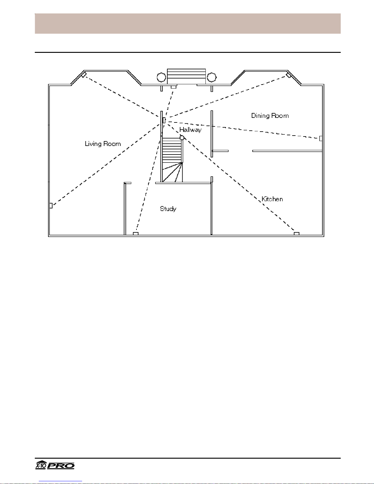
Locating Security System components
Locating the Security Console
Choose a location for the Security Console which is as central as possible in the house,
while providing access to a modular telephone jack and an AC outlet. Fix the console to
the wall using the mounting bracket and screws provided.
For concealed installations the security console may be installed inside a wooden or
plastic cabinet.
Note: Do not install the console inside a metal cabinet since this will block the RF signals
from sensors and remotes and prevent the system from working.
The installer can configure the console (via downloading) to dial out without activating
the built-in siren to prevent an intruder from locating the console by sound. Plug-in Power
Horn sirens elsewhere in the house will continue to operate.
Locating Door/Window Sensors and Motion Detectors
Plan the location of the Door/Window Sensors and Motion Detectors so that the RF path
which runs in a straight line from sensor to console is not obstructed by large metal
objects such as a refrigerators or freezers, and passes through as few walls as possible.
Door/Window Sensors may be hidden behind drapes for a more discreet installation.
Tampa, FL33618 Technical Support: 800 832 4003
5
PRO2000_DR/AB-6/98
Page 6
™
®
Installation
Security Console
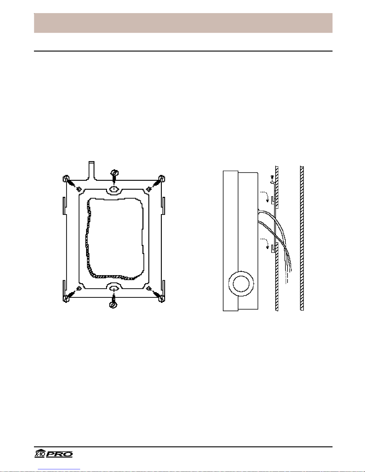
Mounting the console
The Security Console is designed to be installed on a hollow section wall or mounting
panel. A hole is cut into the wall to allow the telephone and power cables to run out
behind the console. A metal bracket is provided which is screwed to the panel. Hooks on
the bracket locate in slots at the back of the console. A small machine screw is provided
which may be used to prevent the unit from being lifted off the hooks.
Tampa, FL33618 Technical Support: 800 832 4003
6
PRO2000_DR/AB-6/98
Page 7
™
®
Installation
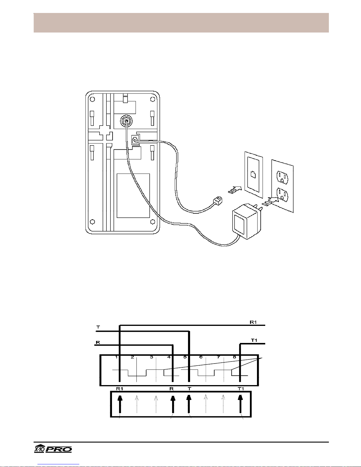
Attaching cables/RJ31X Jack Installation
A telephone cord terminated with an RJ31X connector is provided for telephone
connection. This ensures that the Console will ALWAYS dial out when tripped, even if the
phone line is busy at the time. Note the RJ31X jack to which you connect the Console
might have to be installed by the phone company.
RJ31X
Jack
The wiring diagram for an RJ31X connector is shown below. The connections labeled R
and T should be connected to the Tip & Ring connections coming into the house from the
telephone company. You then connect the red and green that goes to all the phones in the
house to T1 and R1. When the RJ31X plug is removed, the shorting bars connectsT1 to T
and R1 to R. When the RJ31X plug is inserted it opens this path, but the PRO2000 panel
closes this connection again. When an alarm occurs the PRO2000 opens this connection
(to disconnect all phones in the house) and dials out on the yellow and black wires which
are connected to T and R.
FROM
TELEPHONE
COMPANY
RJ31X
RECEPTACLE
BLOCK
MALE
RJ31X PLUG
FROM PRO2000
RED YELLOW BLACK GREEN
WIRE COLORS IN CABLE FROM PRO2000
TO
HOME
PHONES
SHORTING BARS
SHORT REMOVED
ON PLUG INSERTION
Tampa, FL33618 Technical Support: 800 832 4003
7
PRO2000_DR/AB-6/98
Page 8
™
®
Installation
Installation
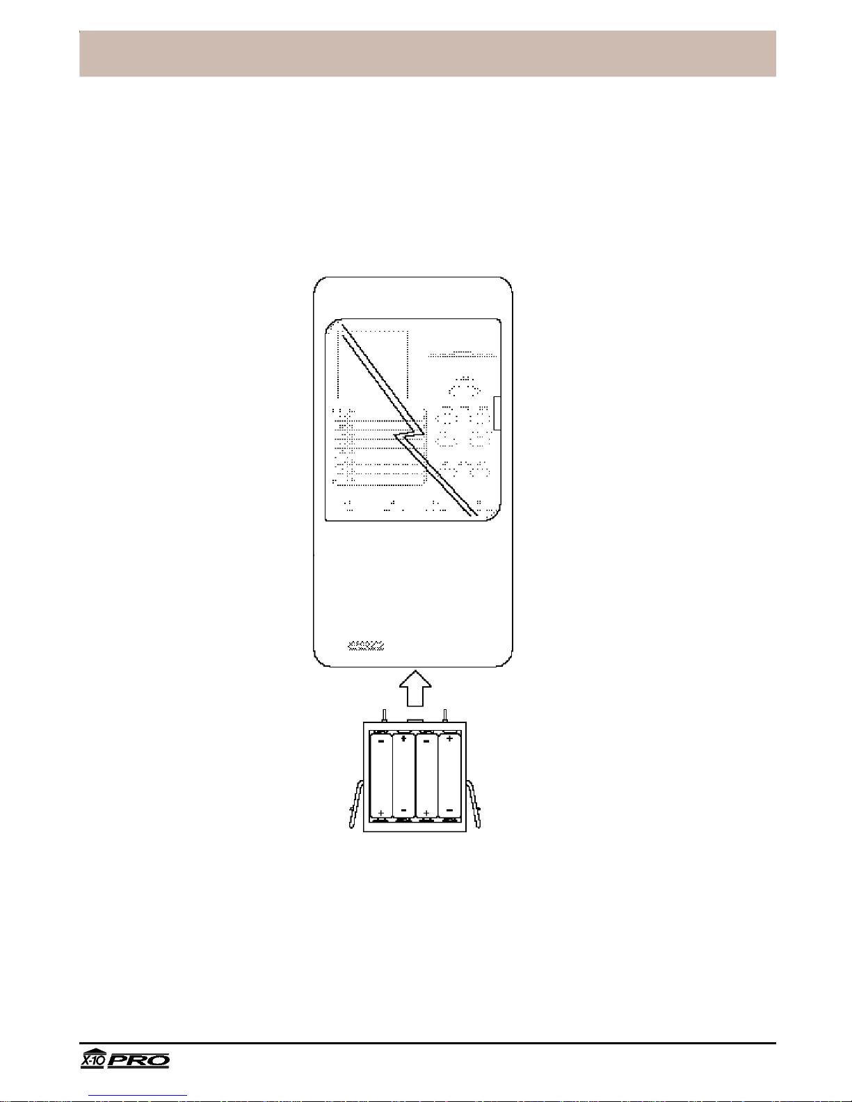
Fitting backup batteries
Slide out the battery drawer from the bottom of the console and insert four AA Alkaline
batteries. Refit the drawer making sure it is fully home in the cabinet. When AC power is
applied the battery LED on the front panel will go out. It is not necessary to disconnect
power to the console when fitting or replacing batteries.
Tampa, FL33618 Technical Support: 800 832 4003
8
PRO2000_DR/AB-6/98
Page 9

™
®
Installation
Security Remote
Registering the Security Remote with the Security Console
• Set the code dial on the Security Remote to the same House Code as the
programmed in the Security Console.
Note: The House Code for the Security System is downloadable. The default setting is
House Code A.
• Fit four AAA Alkaline batteries in the battery compartment in the back of the remote.
• Set the slide switch on the Security Console to INSTALL.
• Press ARM on the Security Remote. The console chimes once to confirm that the
keychain has been registered.
• Return the console slide switch to the RUN1 or RUN2 position.
Note: If the remote did not register, remove the label on the front and use a pencil or
other pointed object to press the small CODE button to generate a new random code.
Press ARM again to install the remote.
Testing the Security Remote
• Set the slide switch on the security console to RUN1 or RUN2.
• Press ARM AWAY on the remote. The console chimes once to confirm and the ARM
indicator lights up. Press DISARM.
• Press SECURITY LIGHT ON and OFF to control a light connected to a lamp module
with code dials set to A13 (or other code downloaded during installation).
Tampa, FL33618 Technical Support: 800 832 4003
9
PRO2000_DR/AB-6/98
Page 10
™
®
Installation
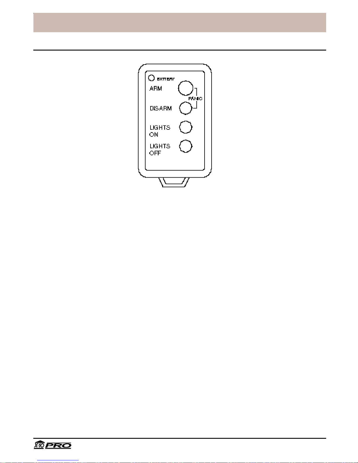
Keychain Remote
Registering the Keychain Remote with the Security Console
• Fit two AAA Alkaline batteries in the battery compartment in the back of the Keychain
Remote.
• Press and hold the ARM button for about a second. The LED indicator flashes twice
when you release it. This confirms the Keychain Remote has generated a new
security code.
• Set the slide switch on the Security Console to INSTALL.
• Press ARM. The console chimes once to confirm that the Keychain Remote has been
registered.
• Return the console slide switch to the RUN1 or RUN2 position.
Testing the Keychain Remote
• Set the slide switch on the Security Console to RUN1 or RUN2.
• Press ARM on the Keychain Remote. The console chimes once to confirm and the
ARM indicator lights. Press DISARM.
Note: The Keychain Remote always arms the system instantly - there is no exit or
entry delay.
• Press LIGHTS ON and LIGHTS OFF to turn on and off a light connected to a lamp
module with code dials set to A13 (or other code downloaded during installation).
• Press ARM and DISARM together to trip the panic alarm. Press DISARM to stop the
alarm.
Tampa, FL33618 Technical Support: 800 832 4003
10
PRO2000_DR/AB-6/98
Page 11

™
®
Installation
Door/Window Sensor
Ideal location
Two windows (requires
accessory magnetic
switch pair)
Sliding window
Installing the Door/Window Sensor
• Attach the Door/Window Sensor to the wall using the mounting screws provided.
• Fit the Door/Window Sensor as high as possible at the top of the door/window.
• Make sure the arrows on the magnetic switch halves are facing each other and that
they separate cleanly when the door or window is opened.
• Set the DELAY slide switch to MIN to always trigger the alarm instantly (for windows),
or to MAX to trigger the alarm after a preset entry delay when the system is armed in
DELAY mode (for doors).
Registering the Door/Window Sensor with the Security Console
• Fit two AA Alkaline batteries in the battery compartment.
• Press and hold the TEST button for about a second. The LED flashes twice when you
release it. This confirms it has generated a new security code.
• Set the slide switch on the Security Console to INSTALL.
• Press the TEST button on the Door/Window Sensor. The console chimes once to
confirm and the next available zone LED lights.
• Return the console slide switch to the RUN1 or RUN2 position.
Testing the Door/Window Sensor
• Set the slide switch on the security console to RUN2.
• Open the door or window with the sensor attached. The console chimes to
acknowledge and the zone LED lights.
Tampa, FL33618 Technical Support: 800 832 4003
11
PRO2000_DR/AB-6/98
Page 12

™
®
Installation
Motion Detector
Installing the Motion Detector
• Attach the Motion Detector to a wall at a height of 5 to 6ft using the mounting bracket
and screws provided.
Note: The Motion Detector has a special lens that 'looks' downwards. It must therefore
be mounted to face outwards horizontally, i.e. do not 'aim' the sensor downwards.
• Set the slide switch to position 1 for instant triggering for maximum sensitivity or
position 2 to trigger only after two movements have been sensed.
Registering the Motion Detector with the Security Console
• Fit four AA Alkaline batteries in the battery compartment.
• Press the CODE button using a pencil or other pointed object to generate a new
security code.
• Set the slide switch on the Security Console to INSTALL.
• Press the TEST button on the Motion Detector. The console chimes once to confirm
and the next available zone LED lights.
Note: If the Motion Detector senses movement before you press the TEST button it
may register itself automatically. You may want to keep the batteries out of the Motion
Detector until you are ready to install the zone, or install the Motion Detectors last.
Tampa, FL33618 Technical Support: 800 832 4003
12
PRO2000_DR/AB-6/98
Page 13

™
®
Installation
Testing the Motion Detector
• Set the slide switch on the Motion Detector to position 1.
• Press and hold the TEST button for about a second. The LED flashes twice when you
release it.
• Wait 20 seconds for the sensor to settle.
• Walk in front of the Motion Detector. The indicator LED lights each time it senses
movement. Check the coverage area and reposition the sensor as required.
• Press the TEST button to return to normal operating mode.
Note: The Motion Detector will automatically return to normal operating mode after
about 2 minutes.
Tampa, FL33618 Technical Support: 800 832 4003
13
PRO2000_DR/AB-6/98
Page 14

™
®
Installation
Power Horn™ Remote Siren
Installing the Power Horn
• Set the House Code dial to the same House Code as the Security System
Note: The House Code for the Security System is downloaded during installation. The
default setting is House Code A.
• Set the Unit Code dial to the same code as the security light. (default is 13.)
Note: If the owner does not wish the Power Horn to be triggered when the security
light is switched on, the installer can re-configure the console to issue a sequence of
All Lights On/All Units Off commands during an alarm instead of flashing just the
security light. The Unit Code for the Power Horn can then be adjusted to any other
(unused) setting, and so will not be triggered when the security light is turned on.
• Plug the Power Horn into a convenient AC outlet, preferably an unswitched one to
ensure that the Power Horn cannot be turned off accidentally.
Testing the Power Horn
• Press the ON button followed by the OFF button, followed again by the ON button, on
any X-10 controller or remote which is set to the same House Code and Unit Code as
the Power Horn. The siren will activate and will continue for 4 seconds, or until two
OFF commands are received in succession.
• Trigger the security system by pressing the PANIC button on the console or on a
remote. The Power Horn will be activated automatically in the next 4 seconds after the
alarm has been triggered and will continue for around 4 seconds after the system is
disarmed.
Tampa, FL33618 Technical Support: 800 832 4003
14
PRO2000_DR/AB-6/98
Page 15

™
®
Installation
Lamp Module
Installing the Lamp Module to control the security light
• Set the House Code and Unit Code dials to match the security light code downloaded
by the installing security firm. This allows it to be controlled from the security light
buttons on the remotes, and to be flashed by the console during an alarm. The default
code for the security light is A13.
• Plug a lamp into the Lamp Module and plug the Lamp Module into a convenient AC
outlet, preferably an unswitched one to ensure that the lamp will always operate when
the alarm is triggered.
Installing the Lamp Module to control other lights
• Set the House Code dial to match the security lamp code downloaded by the
installing security firm. The default House Code is A.
• Set the Unit Code dial to an unused code which can be controlled from the Security
Remote (switches 1-4 control Unit Codes 1-4) or from any other remote or plug-in
controller as required.
• Plug a lamp into the Lamp Module and plug the Lamp Module into a convenient AC
outlet, preferably an unswitched one to ensure that the lamp will always operate when
the alarm is triggered. The lamp's switch must be left on, the Lamp Module will control
whether or not the lamp is switched on or off.
Local control
The Lamp Module includes circuitry to sense the lamp's own on/off switch to turn the
lamp on locally. To switch a lamp on, turn the lamp's own switch off then on again.
Tampa, FL33618 Technical Support: 800 832 4003
15
PRO2000_DR/AB-6/98
Page 16

™
®
Installation
Other X-10 PRO products
Modules
A wide range of switch and control modules are available from X-10 Pro, all of which
can be controlled from the same remote controls which are used to operate the security
system. Modules available include replacement wall switches, X-10 controlled AC
outlets, screw-in lamp modules, plug-in appliance modules and many others.
Remotes
As well as being able to add up to 16 security remotes to the system, it is also possible
to add any number of Home Automation wireless remotes such as the handheld Sixteen
Plus™ remote which controls up to 16 modules around the house.
Controls
A range of plug-in controls are available including the Mini Timer which can control up
to four modules with two on/off times each day, the Telephone Responder which allows
the owner to use any touch tone 'phone to call home and control X-10 Pro modules, and
products which allow any Windows™ or DOS PC to control X-10 functions.
Special products
For special installation requirements a range of accessory products are available
including powerline filters for multiple installations in close proximity, RF and powerline
repeaters for larger installations and interface modules to tie-in X-10 control with third
party security products.
Tampa, FL33618 Technical Support: 800 832 4003
16
PRO2000_DR/AB-6/98
Page 17

™
®
Monitoring Service Setup
Introduction
Digital monitoring
The X-10 PRO2000 Security System incorporates professional digital communicator
technology. Features supported include account number downloading and verification,
remote configuration and alarm type confirmation, and line seizure.
When one of the sensors is activated while the system is armed, the built-in siren will sound.
If the alarm is not disarmed within the next few seconds using one of the security coded
remote controls, the security system console will automatically dial the monitoring station
and send a digitally coded message allowing the station operator to identify the owner's
address, telephone number and the type of alarm that occurred.
Automatic lighting control
When the X-10 PRO2000 Security System is armed in the away mode, an automatic
timer can be activated to turn lights, stereos, TVs, etc. on and off at random times to
make the home look lived in.
Part of the information downloaded to the console includes three Unit Codes for X-10
modules which are used to control lamps and appliances chosen to make the home
look lived-in.
When armed in the AWAY mode, the console turns the three modules on and off
randomly between dusk and the Security Light OFF time. These modules are typically
used for inside lights and a radio or stereo to give the impression that the home is
occupied.
A code is downloaded to give the location (longitude and latitude) of the home, which is
used by the console to calculate the time of dusk. An additional time is downloaded to
specify when lights should all turn off. Daylight savings time is also taken into account.
In addition to the three modules described above, the designated security light is turned
on at dusk and turns off at the security light off-time (this is the same light that is flashed
during an alarm and can be controlled by the Keychain and Security/Home Automation
remotes). This could be used to control an outside security light for example.
Any X-10 controlled modules may be used for the automatic lighting control function,
including wall switches, controlled outlets and plug-in modules. These modules can also be
controlled using any X-10 remote control.
Options downloaded by the security installation firm
The options listed on the following pages are downloaded by the installing security firm
when the system is first set up. These options should therefore be agreed with the
customer prior to setting up the system.
Any of these options can, be changed by the installer at a later date upon request.
Tampa, FL33618 Technical Support: 800 832 4003
17
PRO2000_DR/AB-6/98
Page 18

™
®
Monitoring Service Setup
The above screen shows the options that can be downloaded to the Console.
1. Account number- The customer's 4 digit account number.
2. 1st Monitoring Station Number- The 1st number the console will dial to call the
monitoring station.
3. 2nd Monitoring Station Number- Back-up phone number for the monitoring station
in case the first number doesn't respond.
4. Service Station Number- Number for the service station, for reporting in
periodically (if desired). Note separate software (Call-in Logger from setup disk)
and a stand alone computer are required to log these calls. If not used, enter "1".
5. Customer Service Number- This is the number called when the Monitor button is
pressed. It is normally set up during initial download to call a number that has been
designated for customer service. This acts like a speed-dial button for the customer.
6. Exit delay- The amount of time after leaving the house before the console is armed.
(0-1000 seconds). The default is 60 seconds.
7. Entry delay- The amount of time allowed to enter the home and disarm the console
before the alarm is triggered. (0-1000 seconds). The default is 30 seconds.
8. Delay before dialing- The amount of time the console will wait after it has been
triggered before calling the monitoring station (to give the owner time to disarm the
system before it dials in case of a false alarm). The default is 40 seconds.
Tampa, FL33618 Technical Support: 800 832 4003
18
PRO2000_DR/AB-6/98
Page 19

™
®
Monitoring Service Setup
9. Test Dial Frequency- How many days between each time the console calls the
Service Station (Call-in Logger Software) to check-in. Default is 10 days. Note: If not
used, enter "0".
10. Daylight parameters- Sets dusk times for midsummer and midwinter to activate
lived-in look lighting control (see option 15). Dusk times for the rest of the year are
calculated automatically. Defaults are 10pm in midsummer and 4pm in midwinter.
11. Security Light off time- Time for the security lights (Unit Code 1, from the software
page, has a default Unit Code of 13) to turn off after they have been turned on
automatically at dusk. Note: This functions in both armed or not armed states.
12. Daylight Savings Date- Date for daylight savings time (leave as default for
automatic calculation).
13.Housecode- Housecode setting for all controlled modules. Default setting is A. The
selected House Code will allow the panel to receive wireless Light /Appliance
commands from an X-10 handheld RF transmitter and insert them on the powerlines
14. Unit Code 1(Security Light) to flash lights and turn on at dusk- The default setting
is code 13.
15. Unit Codes 2, 3, 4 for Lived-in look- To control lights and appliances and make the
home look lived-in (active only if the console is armed in the away mode). The
default settings are 14, 15, and 16.
16.Unit Code 5 - Turns on when the system is armed in the away mode and and turns
off when the system is disarmed. This lets you set back heating/air conditioning while
you're away, as an example. Default setting is B12.
17. Tone or Pulse dialing- To change the dialer to touchtone or pulse dialing. The
default is tone dialing. Check the box for pulse dialing.
18. X-10 flashing during alarm- If this option is turned off, the lights will not flash when
the alarm is triggered, although the console will still dial out. The default is flashing.
19. Dialing enabled- If this option is turned off the console will NEVER dial out. This
option is turned off at the factory and should be turned on by the installer during
setup, by checking this box before downloading.
20. No Console Siren during alarm- If this box is checked, the siren will not sound
when the alarm is triggered (silent alarm), although the console will still dial out.
The default is (un-checked) Siren Enabled.
21. Enable Unit Code 5-If this box is checked the module set to this code (default B13)
turns on when the system is armed in the away mode and and turns off when the
system is disarmed. Can be set to any code A-P and 1-16 before download.
22. Chirp sound on alert- If chirp is ON, the console will chirp once per minute when it
needs programming. The default is OFF. This warns the customer of a failed
communication to the monitoring station.
23. Panic always dials- If this option is set to ON, the console will dial out whenever
PANIC is pressed. If this option is set to OFF, the console will only dial out when
PANIC is pressed and the system is armed. Default is always dials.
Tampa, FL33618 Technical Support: 800 832 4003
19
PRO2000_DR/AB-6/98
Page 20

™
®
Monitoring Service Setup
24. Monitor alert set- Set at the factory to cause the Console's monitor light to flash to
alert the user to contact the installer for setup. This warns the customer of a failed
communication to the monitoring station. Should be set to off by the installer during
setup, before downloading.
25. 50 Hz Operation- Default is 60 Hz (for USA) .
26. Daylight savings active- Check or uncheck before downloading depending on time
of year.
27. Disable Daylight savings - Check if daylight savings is not observed in your State.
28. All Lights Flash- Check to flash All lights connected to X-10 PRO Lamp and Wall
Switch Modules (set to the same Housecode as downloaded) when the alarm trips.
Uncheck to only flash lights connected to Modules set to the Security Light Unit
Code 1, (default Unit Code A13).
29. Enable Entry Light- Check this to have the security light (default A 13) turn on
during the entry delay. (Always turns on during exit delay, or for one second if armed
in Instant mode).
Setting up for Monitoring Service.
There are three ways you can set up the Console for monitoring service:
1. Program it from the computer at your office then take it to the customer's location.
All phone numbers and options are permanently stored in the Console in EEROM
(Electrically Erasable Read Only Memory) until you change them by downloading
again. You should however install the back-up batteries so that the clock in the unit
is kept at the correct time during relocation.
2. Program it on-site using a laptop computer.
3. Remotely program it over the phone line at the customer's location from the
computer at your office. Somenone needs to be at the receiver site to push the
Monitor Button upon call in from installer.
For options 1 and 2 (direct modem connection):
Connect the console directly to your computer's modem using a standard RJ11 phone
cord. Run the PROware2000 software. A screen as shown on page 18 will appear. Click
on Modem Setup and select the COM port that you connected the Console to.
Select which options, phone numbers etc. are required (consult with the user regarding
what options are desired).
Set the Console to RUN mode and press the MONITOR button (under the small flip-up
lid, called Set-up, under the main cover).
Wait approx 5 seconds. Then click on Download. The Status line will show a series of
options being downloaded to the Console and the Console will chime twice after a
successful download.
Make sure the customer fills out and signs the monitoring agreement.
Tampa, FL33618 Technical Support: 800 832 4003
20
PRO2000_DR/AB-6/98
Page 21

™
®
Monitoring Service Setup
If the modem does not initialize you might not have the correct initialization string
set for your type of modem. The default setting is for a US Robotics modem, and is as
follows.
AT&F1 &N1 S9=1 S10=250 S27=1 Where:
&F1 *restores the factory profile 1 (hardware flow control).
&N1 *forces connection rate of 300 baud
S9=1 *gives a 0.1 second carrier detect response time.
S10=250 *allows a loss of carrier for 25 seconds before hanging up.
S27=1 *Enables ITU-T V.21 modulation at 300 bps
Modem hang-up string: This defaults to the standard ~~~+++~~~ATH0
Modem answer string: This defaults to the standard ATA
*The above are the parameters required by the downloading program. Each brand
and type of modem uses a different Initialization String to represent the required
peramitters.
Consult the owner's manual for your modem to find out what commands your
modem requires to set it as above. For example: For a Zoom modem the initialization
string is:
AT&F &C1 B0 S7=59 S9=1 S10=250 S37=1 N0. Where:
&F restores the factory profile.
&C1 makes the Data Carrier Detect follow the state of the remote carrier.
B0 selects ITU-T protocol.
S7=59 allows a wait of up to 59 seconds for receipt of the remote carrier.
S9=1 gives a 0.1 second carrier detect response time.
S10=250 allows a loss of carrier for 25 seconds before hanging up.
S37=1 instructs the modem to connect at 300 baud.
N0 fixes the handshake at the S37 value.
For option 3 (downloading from a remote computer):
Have the customer call you from the same phone line that the Console is connected to
(or call them). Ask the customer to set the Console to Run and then press the MONITOR
button (under the small flip-up lid (Set-up) under the main cover). Immediately after
pressing MONITOR the customer should hang up. When the customer hangs up, you
click on Download. After a successful download the Console chimes twice.
Note; the data format downloaded to the Console is a proprietary format and requires
the downloading software supplied by X-10PRO. However when the alarm trips the
format transmitted to the monitoring station complies with industry standard 4 + 2 format.
The Console can optionally be set to call a stand alone computer (Service Station
from the software screen) on a periodic basis. When it does this it reports its
information in "modem-speak." Proprietary software ( Call-in Logger from PROware
Software) is required in order to receive this data and hence use this option. This does
not take the place of a monitoring station!
Tampa, FL33618 Technical Support: 800 832 4003
21
PRO2000_DR/AB-6/98
Page 22

™
®
Battery Information
General
X-10 PRO Door/Window Sensors, Motion Detectors and Security, Keychain remotes are
designed to operate for approximately two years when fitted with alkaline batteries.
However, since environmental and operating conditions vary from installation to
installation it is recommended that all batteries are replaced once a year.
Security Console
Battery backup
The batteries in the Security Console are used as a backup when there has been a
power failure. The batteries provide approx. 48 hours of backup time provided the alarm
has not been triggered.
While on battery backup, the console will continue to operate, and will sound the siren
(if enabled) and dial out if the alarm is triggered. It will not, of course, flash the house
lights or trigger Power Horn sirens.
If both the AC supply and batteries fail, the console will no longer dial out or sound the
siren, but it will retain all configuration data (telephone numbers, entry/exit delays etc.)
as well as the security codes for the remotes and sensors. However, the time and date
will be lost and will need to be redownloaded from the installing security firm.
Battery Replacement
Batteries can be replaced at any time, even while the unit is powered up - there is no
need to disconnect the AC adapter. There is no special procedure for battery
replacement.
Security and Keychain Remotes
Battery Replacement
Providing the batteries have not already failed, they may be replaced with fresh
batteries without the need to re-install the remote. After removing the old batteries fresh
batteries must be fitted within 30 seconds to ensure that the security code is retained.
Once the batteries have been replaced, confirm that the remote is still logged in by
arming the system. If it does not arm, the code has been lost and you will need to
proceed as described below.
If the batteries have failed completely, the security code will have been lost. To ensure
proper system integrity it is recommended that the console is cleared and all sensors
and remotes re-installed following the procedures in the Installation chapter.
Tampa, FL33618 Technical Support: 800 832 4003
22
PRO2000_DR/AB-6/98
Page 23

™
®
Battery Information
Door/Window Sensors and Motion Detectors
Battery Replacement
If any of the Console's zone indicators flash slowly, the Motion Detector or Door/Window
Sensor for that zone has not reported in during the last four hours. This is most likely
caused by a dead battery.
As with the remotes, as long as the batteries have not completely failed they may be
replaced with fresh batteries without the need to re-install the sensor. After removing the
old batteries fresh batteries must be fitted within 30 seconds to ensure that the security
code is retained.
Testing the Door/Window Sensor
Once the batteries have been replaced, the Door/Window Sensor should be tested as
follows:
• Set the slide switch on the security console to RUN2.
• Open the door or window with the sensor attached. The console chimes to
acknowledge and the zone LED lights.
Testing the Motion Sensor
To test the Motion Detector:
• Set the slide switch on the security console to RUN2.
• Press the TEST button on the back of the Motion Detector. The console chimes to
acknowledge.
Clearing remotes & sensors from the console
If you suspect that a neighboring system is causing false alarms, or if you need to reinstall remotes, Door/Window Sensors and Motion Detectors for any other reason, you
can clear all sensors and remotes from the console's memory as follows:
• Set the console to INSTALL.
• Press PANIC, ARM HOME and ARM AWAY at the same time.
• Set the slide switch back to RUN1 or RUN2
Note: Telephone numbers and configuration data downloaded by the installing security
firm (such as entry and exit delays etc.) cannot be erased, and can only be changed by
the installer on request.
Tampa, FL33618 Technical Support: 800 832 4003
23
PRO2000_DR/AB-6/98
Page 24

™
®
Troubleshooting
SOLUTIONPROBLEM
If the system does not arm.
• Check that the slide switch under the
SET UP flip door is set to RUN1 or
RUN2.
• Check that the battery indicator on the
Remote Control turns on when you
press ARM. Replace the battery and
reinstall the Remote if necessary.
• Make sure all zones are closed and
the Motion Detector is not triggered.
If a zone indicator flashes slowly. One of the sensors/motion detectors has
not reported in, in the last 4 hours.
Check that the battery in the sensor/
motion detector is good.
If you need to arm the system and want
to ignore a sensor/motion detector which
is not functioning:
1. Press ARM on the Remote control.
You hear a repetitive trouble alarm to
alert you that there is a problem.
If a zone indicator flashes rapidly.
2. While the trouble alarm is sounding,
press BYPASS on the Console. The
zone indicator flashes rapidly.
Then press ARM on the Remote Control.
The problem zone will be Bypassed but
all other zones are armed.
Note: if you bypass an open window and
arm the system (as described above)
and later close the window, that zone will
now arm and its zone light will stop
flashing.
The BYPASS button was pressed to arm
the system while a sensor/motion
detector was reporting a problem.
Tampa, FL33618 Technical Support: 800 832 4003
24
PRO2000_DR/AB-6/98
Page 25

™
®
Troubleshooting
PROBLEM SOLUTION
If you hear a repetitive trouble alarm
when you try to arm the system, and it
does not arm.
If the alarm trips when you enter the
house before you have time to disarm it.
Check the zone indicators. If a door or
window is open, its zone indicator is on. If
there is a problem with a Sensor or
Motion Detector, its zone indicator
flashes slowly. Either:
• Press DISARM. Check each Door/
Window Sensor is working properly
and that no doors or windows are
open. Then arm the system.
Or:
• While the trouble alarm is sounding,
press BYPASS to override the problem
zone (its zone indicator then flashes
rapidly). Then arm the system again.
Arm the system in the delay mode.
To do this: Set the MIN/MAX switch on
the entrance Door/Window Sensor to
MAX and the Remote Control to MAX (on
the Hand held Security Remote) and
then press ARM.
Lights will not turn on or off from the
LIGHT ON or LIGHT OFF buttons on the
Remote Control.
Tampa, FL33618 Technical Support: 800 832 4003
• Be sure you set House and Unit
Codes on the module(s) to the same
letter and number as downloaded to
the Console Security Light (default is
A-13).
• Be sure the light you are trying to
control has its on/off switch in the on
position.
• Be sure its bulb is good.
• Plug the module into another outlet
near the Console.
• Check that the battery indicator on the
Remote Control comes on when you
press a button. Replace battery and
re-install remote if necessary.
• Make sure Panel Power Supply is
plugged in, not running on battery.
25
PRO2000_DR/AB-6/98
Page 26

™
®
Troubleshooting
PROBLEM SOLUTION
You open a door or window and the
alarm does not trip.
If appliances turn off during an alarm.
• Check that the system is armed.
• Be sure the slide switch under the
SET UP flip door is in the RUN1 or
RUN2 position.
• Make sure the arrows on magnetic
contacts are facing each other.
• Check to see if the alarm trips when
you press TEST on the Door/Window
Sensor.
• If the alarm does not trip when you
press TEST, check that the indicator
on the sensor comes on when you
press TEST.
If the indicator does not come on,
replace the battery and re-install the
sensor if necessary.
The system flashes lights by repetitively
transmitting on/off commands for a
specific code Security Light (default
A13), or optionally by flashing all lights
on/all units off.
If you do not hear a chime from the
Console when you press ARM to install
a Remote Control.
Tampa, FL33618 Technical Support: 800 832 4003
If the console has been set to transmit all
lights on/all units off, any appliance
module set to the same House Code as
the console will turn off.
Check to see if you can arm the system
when the Console is in the RUN mode. If
you can, the Remote Control is already
installed and no further action is
necessary. If not:
1. Check that the console is set to the
INSTALL mode.
2. Re-initialize the remote (see page 8 &
9).
26
PRO2000_DR/AB-6/98
Page 27

™
®
Troubleshooting
PROBLEM SOLUTION
If you do not hear a chime from the
Console when you press TEST to install
a Door/Window Sensor or Motion
Detector.
If the battery indicator on the Console is
on.
With the Console in the RUN 2 mode,
check that it chimes when you press
TEST on the sensor/motion detector. If it
does, then the sensor/motion detector is
already installed and no further action is
necessary. If not:
1. Check that the Console is set to the
INSTALL mode.
2. Change the code on the sensor/
motion detector (see Setting Up Door/
Window Sensors and Setting Up Motion
Detectors on page 11).
Replace the console's battery. 4 AA 1.5V
alkaline batteries provide approximately
48 hours of back-up. Replace battery at
least once a year.
If you lose your remote control.
If the system Arms or Disarms by itself
If the red light on the Security Remote
Control stays on during installation.
Re-install your complete system to
prevent someone else from using the
lost remote control.
A neighbor may have a compatible
system. Re-install the complete system
so that it chooses different RF codes.
Press CODE (under the clear plastic liner in
front of the remote) then press ARM. If it still
stays on, remove the battery, wait a few
seconds, then replace the battery. Press
CODE then press ARM again and install.
Tampa, FL33618 Technical Support: 800 832 4003
27
PRO2000_DR/AB-6/98
Page 28

™
®
Troubleshooting
PROBLEM SOLUTION
If the armed indicator is flashing. This indicates that there has been an
intrusion. Also, if a zone indicator is on,
this indicates which zone was violated. To
turn the zone indicator off, and stop the
armed indicator from flashing press ARM
then DISARM on the remote control. If a
zone indicator is not lit, the violated zone
may have been one of the second eight
zones. Press BYPASS to see which zone
was tripped.
If the POWERHORN does not trip when
the alarm trips.
The Motion Detector causes false
alarms.
• Be sure you set the dials on the
POWERHORN to the same House
Code and Unit Code as the Security
Light downloaded to the Console
(default A13).
• Plug the POWERHORN into another
outlet near the Console.
• All brands of motion detectors sense
motion by detecting a change in
temperature, therefore do not place
the detector near any sources of heat
such as over an air conditioner or
heating vent.
• Do not place in a direct source of
bright light, such as sunlight. Do not
point directly toward a window.
• Do not place near cellular 'phones or
microwave ovens.
The MONITOR light is flashing.
Tampa, FL33618 Technical Support: 800 832 4003
This means that you need to call the
installing security firm to set up of the
console. After installation, this could be
caused by a failure to communicate with
the monitoring station over the phone
lines. Check for proper RJ31X
installation: see page 7.
28
PRO2000_DR/AB-6/98
Page 29

™
®
Troubleshooting
Special Notes
Intercom Systems
Intercom systems which send voice signals over existing electrical wiring may interfere
Troubleshooting
with the ability to control modules from your X-10 PRO Security System with the
intercom in use. If the intercom system has its own separate wiring it will not cause a
problem.
Arming
The ARM button on the Console arms the system in the delay mode only. Use a Remote
Control if you want to arm the system in the instant (min) mode.
Outdoor infrared Motion Detector
The Outdoor Motion Detector will not trigger the X-10 PRO Security System. It can,
however, control the same lights that the security system controls.
RF Interference
As with any Radio Transmitter/Receiver, you may experience areas within your
installation that have heavy interference caused by electrical fields radiated from
nearby electronic devices such as: TV's, stereos, computers, etc. Try to locate the
Sensors further from these types of devices. Also, mounting the sensors on metal door/
window frames or on walls with metal studs could cause RF Interference and/or
reflection.
Centrally mounting the Console, with as few walls as possible between it's sensors, will
give you the best possible opportunity of receiving clear signals. However, if you
continue to have a troubled RF area, you can use an X-10 PRO PSX01 Smart Repeater
(located half way between the Console and the Sensor) to repeat the signals to and
from the troubled area. Only one PSX01 may be used per PRO2000 installation.
Tampa, FL33618 Technical Support: 800 832 4003
29
PRO2000_DR/AB-6/98
Page 30

™
®
Notes
Installation Notes and Set-up Sheets
Use the following notes to keep a record of the installation information.
Customer's Name________________________________________________________________
Address________________________________________________________________________
City_________________________________________State________________Zip____________
Home Phone Number_____________________________________________________________
Monitoring Station________________________________________________________________
Customer Service Phone Number___________________________________________________
PRO2000 Download Information
1. Account number-
2. 1st Monitoring Station Number- .
3. 2nd Monitoring Station Number-
4. Service Station Number-
5. Customer Service Number-
6. Exit delay-
7. Entry delay-
8. Delay before dialing-
9. Test Dial Frequency-
10. Daylight parameters-
11. Security Light off time-
12. Daylight Savings Date-
13.Housecode-
14. Unit Code 1(Security Light) to flash lights and turn on at dusk-
15. Unit Codes 2, 3, 4 for Lived-in look-
16.Unit Code 5 -
17. Tone or Pulse dialing-
18. X-10 flashing during alarm-
19. Dialing enabled-
20. No Console Siren during alarm-
21. Enable Unit Code 5-
22. Chirp sound on alert-
23. Panic always dials-
Tampa, FL33618 Technical Support: 800 832 4003
30
PRO2000_DR/AB-6/98
Page 31

™
®
Notes
24. Monitor alert set-
25. 50 Hz Operation-
26. Daylight savings active-
27. Disable Daylight savings -
28. All Lights Flash-
29. Enable Entry Light-
PRO2000 Zone and Remote Set-up
Zone # Type
1
2
3
4
5
6
7
8
9
10
11
12
13
14
(Door/Window/Motion) Name (front door, etc.) Delay/Instant (D/I)
15
16
Number of HandHeld Remotes______
Number of Keychain Remotes______ MAX. COMBINATION 16
Number of Optional Medical Alert Pendants______
Tampa, FL33618 Technical Support: 800 832 4003
31
PRO2000_DR/AB-6/98
Page 32

™
®
Tampa, FL33618 Technical Support: 800 832 4003
32
PRO2000_DR/AB-6/98
 Loading...