

Motion Monitor
Motion Sensor with
Dual Floodlights
Model PR511
™
Owner’s Manual
Whi te (Neut ral )
Black (Live)
White
Black
White
Black
Blue
White
White
Black
House W iring
Wal l Box Groungi ng Scre w
Green
INTRODUCTION
Y our Motion Monitor consists of a main sensor head, dual floodlight lamp holders (bulbs not
included) and a mounting plate. It is designed to be installed indoors or outdoors and should be
mounted on a standard round electrical wall box. When someone approaches your home, the
connected floodlights turn on, and turn off after the delay you set. The unit can also be set to
turn on lights inside your home. You connect these lights to X10 modules (sold separately). You
can set these lights to turn on when motion is detected and/or when it gets dark.
Locating the Motion Monitor
Consider the following points when choosing a location to install the Motion Monitor:
• The Motion Monitor must be at least 6-8 ft. above the ground and be parallel to the
ground. At a 6 ft. height it will have a detection range of approximately 30 ft.
• The floodlights should be aimed away from the Sensor.
• Direct sunlight should not fall on the Motion Monitor lens.
• The Motion Monitor should not face reflective surfaces such as a swimming pool or
large windows.
• Do not mount the Motion Monitor over heat producing vents or air conditioning
units.
• The Motion Monitor cannot “see” through glass.
Note: The sensor “sees” a moving object by detecting a change in temperature. If
you install and set up the Motion Monitor on a very hot day, it will be difficult for the
sensor to detect the difference between the heat from your body and the background
temperature. (At a background temperature of 98.6° F you are invisible to the
sensor). In very hot weather it is recommended that you make test adjustments in the
evening when it is cooler.
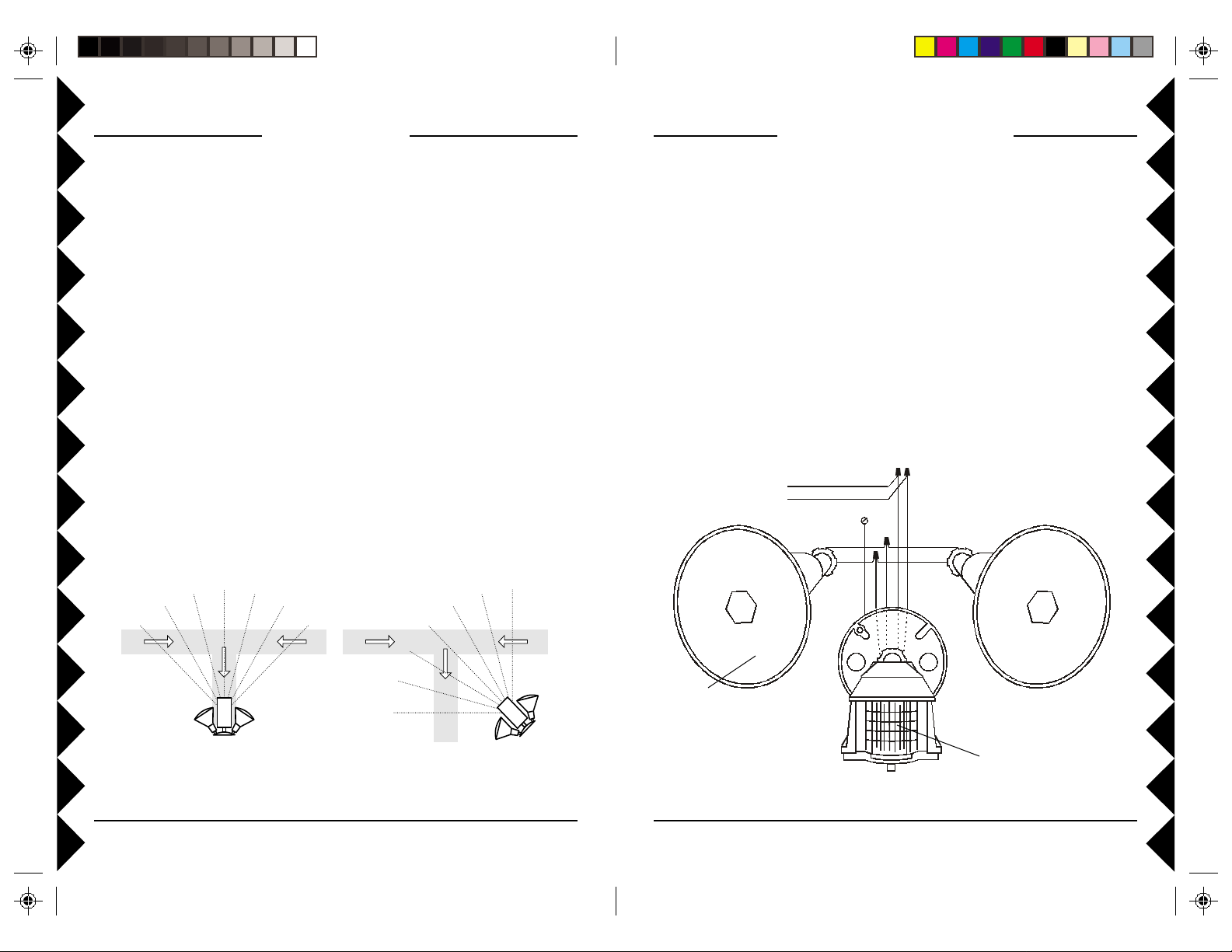
ASSEMBLING THE PARTS
The Motion Monitor mounting plate is designed to fit a standard round outdoor
electrical junction box (not included).
Referring to the diagram below:
1. Screw the base of each lamp holder into the outer holes on the mounting plate.
2. Rotate the locking ring on each lamp holder towards the plate until the lamp holder
is secure against the plate.
3. Screw the threaded end of the Motion Monitor into the center hole on the mounting
plate.
4. Lock the Motion Monitor into place using the locking ring.
5. Locate each lamp holder’s WHITE wire and one of the WHITE wires from the
Motion Monitor and twist all three wires together using a wire nut (supplied).
6. Locate each BLACK wire from the lamp holders and connect them both to the BLUE
wire from the Motion Monitor, again using a wire nut.
7. Make sure no bare whiskers of wire stick out from the wire nuts (cover with electrical
tape if necessary).
Poor location
(movement directly
toward sensor may
not be detected)
Good location
(movement in any
direction will cross sensor
beams and be detected)
Bulbs not
included
Motion Sensor
32

INST ALLATION
You can install the Motion Monitor assembly in a wall box that is powered at all times
or in a wall box that is controlled by a wall switch, but if it is controlled by a wall
switch, make sure you leave the switch on at all times. Turning the switch off will
completely disable the Motion Monitor.
CAUTION: To prevent severe damage to the unit, do not connect it to a wall box that is
controlled by any kind of dimmer or remote controlled switch.
WARNING: Before making the following connections, be sure to turn off the power
to the junction box that you are installing the Motion Monitor Assembly into. If you
don’t, a serious shock hazard will exist!
1. Install the gasket (supplied) onto the junction box, and route the house wiring
through the gasket.
2. Connect the GREEN wire from the mounting plate to the bare ground wire in the
junction box, or ground screw if there is one.
3. Connect the WHITE (Neutral) wire from the Motion Monitor assembly to the house
wiring’s WHITE (Neutral) wire, using a wire nut.
4. Connect the BLACK (Live) wire from the Motion Monitor assembly to the house
wiring’s BLACK (Live) wire, using a wire nut.
5. Make sure no bare whiskers of wire stick out from the wire nuts (cover with electrical
tape if necessary).
6. Secure the mounting plate to the junction box using the screws provided.
7. Secure the insulating ring in each lamp holder and screw a bulb (max. 150W, not
supplied) into each lamp holder.
Live
CONTROLS AND SETTINGS
Adjusting the Motion Monitor Coverage
• Set the DUSK control fully clockwise to LIGHT.
• Set the RANGE control fully clockwise to MAX.
• Set the TIME DELAY to 0.1 minutes (approx. 6 seconds)
using a flathead screwdriver.
• Swivel the sensor head toward the area you want to cover. Be
sure the sensor head remains level from side-to-side and level
with the ground.
• Aim the floodlights at the area you want to light.
• Turn on the power and wait for one minute.
• Walk around the covered area. Whenever the sensor “sees”
you the floodlights turn on and remain on for six seconds after
you stop moving. If necessary, reorient the sensor head so
normal road traffic does not activate the Motion Monitor.
Dusk control
After checking that the unit works during the day with the Dusk
setting turned fully clockwise, you might want to set the unit to only
operate at night. The best setting for the dusk control is indicated by
the index mark. This setting should be tried before making any
further adjustments. The setting of the dusk control is quite sensitive,
so only make small adjustments each time.
• Turn the control toward DARK if the Motion Monitor operates too early in the day.
• Turn the control toward LIGHT if the Motion Monitor operates too late in the day.
• Turn the control all the way to LIGHT for the Motion Monitor to work all the time.
Note: When you change the setting of this control, or when the light level changes, the
new setting does not take effect until 10 minutes after the setting was changed or the
light level changed.
Index mark
Insulating ring
Note: The Motion Monitor has a special lens that “looks”
downwards. It must therefore be mounted to face outwards
horizontally, i.e. do not “aim” the sensor downwards.
Neutral
Ground
Range control
• Turn towards MAX to increase range.
• Turn towards MIN to avoid traffic, pets or small animals triggering the Motion
Monitor.
Time Delay switch
• Set to desired time for lights to stay on after no further motion has been detected.
54

TROUBLESHOOTING
Controls and Settings, cont.
This Unit switch
• Set to SENSOR to have the floodlights turn on when motion is detected.
• Set to DUSK to have the floodlights turn on at dusk and off at dawn.
House Code
• Set the House Code dial to match other X10 Modules that are to be controlled by the
Motion Monitor, and X10 Controllers you want to use to control the Motion Monitor.
Start Code
• This is the “Unit Code” for the Motion Monitor. The Motion Monitor floodlights can
be turned on and off from an X10 controller using this Unit Code.
The Start Code is also the number that is added to the slide switch numbers to set the
Unit Codes for other X10 Modules controlled by the Motion Monitor.
Note: When the floodlights are turned on using an X10 controller, they will stay on
until they are turned off again using an X10 controller.
Sensor switches
• These switches determine which other X10 Modules will be turned on when motion is
sensed. The number next to the switch (+1 to +4) is added to the Start Code to
determine the Unit Code for an X10 Module. (For example, if the Start Code is set to
3 and the Sensor Switch labeled 2 is set to IN, the module with unit code 5 and the
same House Code as the Motion Monitor will turn on when motion is detected).
I.E., Start code (3) plus In/Out switch (+2) = 5. Set the X10 Module inside the house
(having the same House Code) to unit 5 and when motion is detected, the X10
Module set to Unit Code 5 will also cycle with the floodlights.
Dusk switches
• These switches determine which other X10 Modules will be turned on at dusk and off
at dawn. The number next to the switch (+5 to +8) is added to the Start Code to
determine the Unit Code for an X10 Module. (For example, if the Start Code is set to
3 and the Sensor Switch labeled 6 is set to IN, the module with unit code 9 and the
same House Code as the Motion Monitor will turn on at dusk, and turn off at dawn).
Caution: To avoid the risk of fire or injury ensure that potentially hazardous
appliances such as portable heaters or fans will not be accidentally controlled by the
Motion Monitor. Choose controlled Unit Codes carefully.
Problem: Sometimes the Motion Monitor seems less sensitive than other times.
Solution: Observe the notes and diagrams on page 2, and note that the Motion
Monitor is most sensitive when you walk “across” its path. It is also less sensitive in
very hot conditions, i.e., in the summer. (The normal operating temperature range is
-4 deg. F. to +122 deg. F).
Problem: I want to have the lights on for a couple hours for a Barbecue, what do I do?
Solution: Using an X10 Controller, you can send an ON command corresponding to
the Motion Monitor’s Start Code, and it will stay on until an OFF command is sent.
Problem: The floodlights are on constantly and will not turn off.
Solution: If turned on by a command from an X10 Controller, the Motion Monitor
stays on until turned off from and X10 Controller, if necessary send an Off command
to the Motion Monitor from an X10 controller, returning the Motion Monitor to
normal cycling mode.
Also, if the Motion Monitor is accidentally powered off (from a wall switch that
controls the power to it) while the floodlights are on, it will stay on when the power is
reapplied. After dark, (depending on the position of the dusk setting) trigger the
Motion Monitor by walking in front of it, then after the delay time you’ve set the
floodlights will turn off and return to normal operation.
Problem: The Motion Monitor sometimes doesn’t control my X10 Module.
Solution: Check that the Module you’re having trouble controlling is set to match the
appropriate Sensor or Dusk switch on the Motion Monitor, and that the appropriate
Sensor or Dusk switch is set to IN.
Check that the Module’s House Code matches the one set on the Motion Monitor.
Try the Module in different outlets. If that doesn’t help, please visit:
http://www.x10.com/support for more help.
76

X10 Wireless Technology, Inc. Limited One Year Warranty
X10.com, a division of X10 Wireless Technology, Inc. (X10)
warrants X10 products to be free from defective material and
workmanship for a period of one (1) year from the original date of
purchase at retail. X10 agrees to repair or replace, at its sole
discretion, a defective X10 product if returned to X10 within the
warranty period and with proof of purchase. If service is required
under this warranty:
Call 1-800-442-5065, visit www.x10.com, or e-mail
support@x10.com.
For help or more information on setup, please visit:
http://www.x10.com/support
X10.com, a Division of
X10 Wireless Technology, Inc.
3824 North 5th St.,
Suite C, North Las Vegas, NV 89032
http://www.x10.com
PR511-11/02
 Loading...