

Page 1
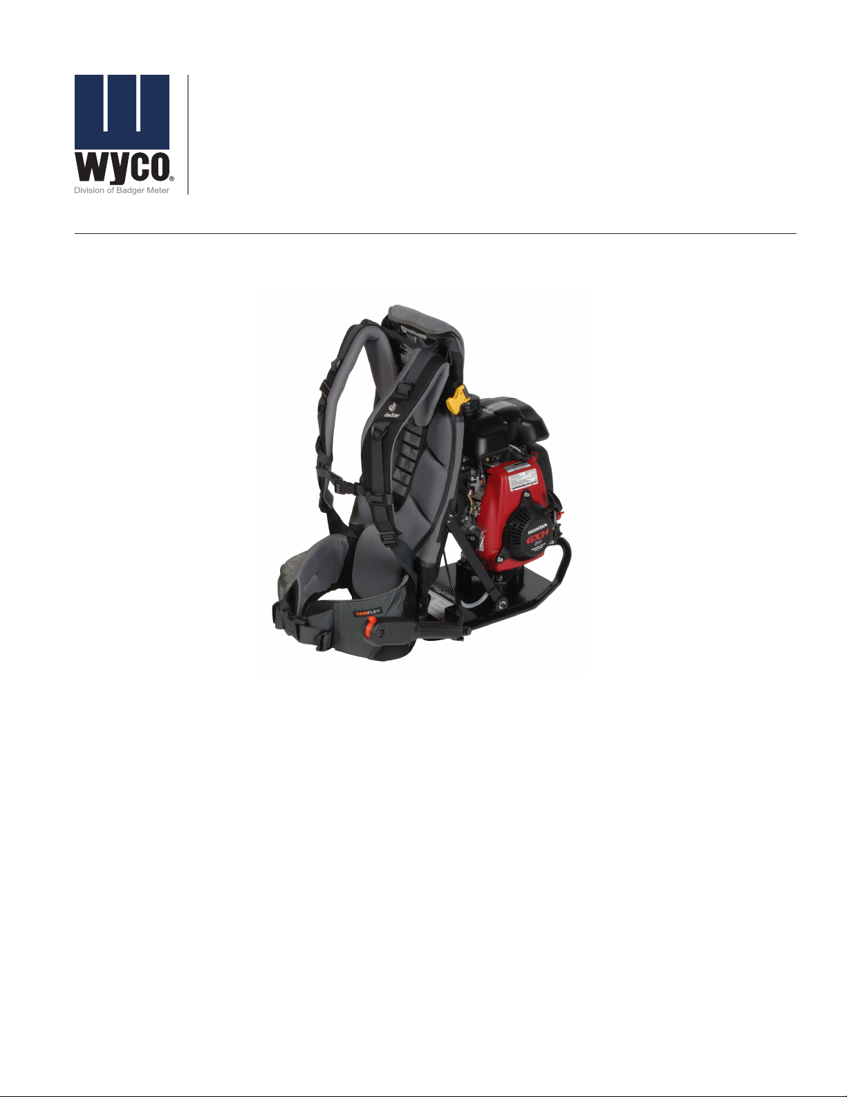
Concrete Vibrator
Backpack Model WBP50
VBR-UM-00173-EN-02 (March 2014)
User Manual
Page 2

Concrete Vibrator, Backpack Model WBP50
Page 2 March 2014
Page 3

User Manual
CONTENTS
Safety . . . . . . . . . . . . . . . . . . . . . . . . . . . . . . . . . . . . . . . . . . . . . . . . . . . . . . . . . . . . . . . . . . . . . . . . . . . . . 5
Benets of Vibration. . . . . . . . . . . . . . . . . . . . . . . . . . . . . . . . . . . . . . . . . . . . . . . . . . . . . . . . . . . . . . . . . . . . 5
Head and Shaft Selection . . . . . . . . . . . . . . . . . . . . . . . . . . . . . . . . . . . . . . . . . . . . . . . . . . . . . . . . . . . . . . . . 5
Adjusting the Backpack . . . . . . . . . . . . . . . . . . . . . . . . . . . . . . . . . . . . . . . . . . . . . . . . . . . . . . . . . . . . . . . . . 6
Frame . . . . . . . . . . . . . . . . . . . . . . . . . . . . . . . . . . . . . . . . . . . . . . . . . . . . . . . . . . . . . . . . . . . . . . . . . . 6
Hip Belt . . . . . . . . . . . . . . . . . . . . . . . . . . . . . . . . . . . . . . . . . . . . . . . . . . . . . . . . . . . . . . . . . . . . . . . . . 6
Shoulder Straps. . . . . . . . . . . . . . . . . . . . . . . . . . . . . . . . . . . . . . . . . . . . . . . . . . . . . . . . . . . . . . . . . . . . 6
Load Lifters . . . . . . . . . . . . . . . . . . . . . . . . . . . . . . . . . . . . . . . . . . . . . . . . . . . . . . . . . . . . . . . . . . . . . . 6
Sternum Strap. . . . . . . . . . . . . . . . . . . . . . . . . . . . . . . . . . . . . . . . . . . . . . . . . . . . . . . . . . . . . . . . . . . . . 6
Final Tweaks . . . . . . . . . . . . . . . . . . . . . . . . . . . . . . . . . . . . . . . . . . . . . . . . . . . . . . . . . . . . . . . . . . . . . . 6
Pre-Operation Checks . . . . . . . . . . . . . . . . . . . . . . . . . . . . . . . . . . . . . . . . . . . . . . . . . . . . . . . . . . . . . . . . . . 7
Is Your Engine Ready to Go? . . . . . . . . . . . . . . . . . . . . . . . . . . . . . . . . . . . . . . . . . . . . . . . . . . . . . . . . . . . . 7
Operation . . . . . . . . . . . . . . . . . . . . . . . . . . . . . . . . . . . . . . . . . . . . . . . . . . . . . . . . . . . . . . . . . . . . . . . . . . 7
Safe Operating Precautions . . . . . . . . . . . . . . . . . . . . . . . . . . . . . . . . . . . . . . . . . . . . . . . . . . . . . . . . . . . . 7
Starting the Engine . . . . . . . . . . . . . . . . . . . . . . . . . . . . . . . . . . . . . . . . . . . . . . . . . . . . . . . . . . . . . . . . . 7
Setting the Engine Speed . . . . . . . . . . . . . . . . . . . . . . . . . . . . . . . . . . . . . . . . . . . . . . . . . . . . . . . . . . . . . 8
Stopping the Engine . . . . . . . . . . . . . . . . . . . . . . . . . . . . . . . . . . . . . . . . . . . . . . . . . . . . . . . . . . . . . . . . 9
Maintenance . . . . . . . . . . . . . . . . . . . . . . . . . . . . . . . . . . . . . . . . . . . . . . . . . . . . . . . . . . . . . . . . . . . . . . . . 9
Flex Shaft Grease . . . . . . . . . . . . . . . . . . . . . . . . . . . . . . . . . . . . . . . . . . . . . . . . . . . . . . . . . . . . . . . . . . . 9
Vibrator Head Lubricant . . . . . . . . . . . . . . . . . . . . . . . . . . . . . . . . . . . . . . . . . . . . . . . . . . . . . . . . . . . . . . 9
Speed Increaser Servicing . . . . . . . . . . . . . . . . . . . . . . . . . . . . . . . . . . . . . . . . . . . . . . . . . . . . . . . . . . . . . 9
Honda Engine GXH50. . . . . . . . . . . . . . . . . . . . . . . . . . . . . . . . . . . . . . . . . . . . . . . . . . . . . . . . . . . . . . . 10
Servicing the Engine . . . . . . . . . . . . . . . . . . . . . . . . . . . . . . . . . . . . . . . . . . . . . . . . . . . . . . . . . . . . . . . . . . 10
The Importance of Maintenance . . . . . . . . . . . . . . . . . . . . . . . . . . . . . . . . . . . . . . . . . . . . . . . . . . . . . . . . 10
Maintenance Safety . . . . . . . . . . . . . . . . . . . . . . . . . . . . . . . . . . . . . . . . . . . . . . . . . . . . . . . . . . . . . . . . 10
Safety Precautions . . . . . . . . . . . . . . . . . . . . . . . . . . . . . . . . . . . . . . . . . . . . . . . . . . . . . . . . . . . . . . . . . 10
Maintenance Schedule . . . . . . . . . . . . . . . . . . . . . . . . . . . . . . . . . . . . . . . . . . . . . . . . . . . . . . . . . . . . . . 11
Refueling. . . . . . . . . . . . . . . . . . . . . . . . . . . . . . . . . . . . . . . . . . . . . . . . . . . . . . . . . . . . . . . . . . . . . . . 11
Engine Oil . . . . . . . . . . . . . . . . . . . . . . . . . . . . . . . . . . . . . . . . . . . . . . . . . . . . . . . . . . . . . . . . . . . . . . 12
Air Cleaner . . . . . . . . . . . . . . . . . . . . . . . . . . . . . . . . . . . . . . . . . . . . . . . . . . . . . . . . . . . . . . . . . . . . . . 13
Spark Plug . . . . . . . . . . . . . . . . . . . . . . . . . . . . . . . . . . . . . . . . . . . . . . . . . . . . . . . . . . . . . . . . . . . . . . 13
Spark Arrester (Optional Equipment) . . . . . . . . . . . . . . . . . . . . . . . . . . . . . . . . . . . . . . . . . . . . . . . . . . . . . 14
Storing Your Engine . . . . . . . . . . . . . . . . . . . . . . . . . . . . . . . . . . . . . . . . . . . . . . . . . . . . . . . . . . . . . . . . 14
Page 3 March 2014
Page 4

Concrete Vibrator, Backpack Model WBP50
Troubleshooting . . . . . . . . . . . . . . . . . . . . . . . . . . . . . . . . . . . . . . . . . . . . . . . . . . . . . . . . . . . . . . . . . . . . . 16
Service . . . . . . . . . . . . . . . . . . . . . . . . . . . . . . . . . . . . . . . . . . . . . . . . . . . . . . . . . . . . . . . . . . . . . . . . . . . 16
Parts. . . . . . . . . . . . . . . . . . . . . . . . . . . . . . . . . . . . . . . . . . . . . . . . . . . . . . . . . . . . . . . . . . . . . . . . . . . . . 16
Honda Engine Parts . . . . . . . . . . . . . . . . . . . . . . . . . . . . . . . . . . . . . . . . . . . . . . . . . . . . . . . . . . . . . . . . 16
Honda Engine Warranty . . . . . . . . . . . . . . . . . . . . . . . . . . . . . . . . . . . . . . . . . . . . . . . . . . . . . . . . . . . . . 16
Wyco Warranty . . . . . . . . . . . . . . . . . . . . . . . . . . . . . . . . . . . . . . . . . . . . . . . . . . . . . . . . . . . . . . . . . . . 16
Wyco Drawings . . . . . . . . . . . . . . . . . . . . . . . . . . . . . . . . . . . . . . . . . . . . . . . . . . . . . . . . . . . . . . . . . . . 16
W402535 Backpack Assembly. . . . . . . . . . . . . . . . . . . . . . . . . . . . . . . . . . . . . . . . . . . . . . . . . . . . . . . . . . 17
W402530 Frame Assembly. . . . . . . . . . . . . . . . . . . . . . . . . . . . . . . . . . . . . . . . . . . . . . . . . . . . . . . . . . . . 18
W402600 Speed Increaser Assembly, 1 of 4 . . . . . . . . . . . . . . . . . . . . . . . . . . . . . . . . . . . . . . . . . . . . . . . . . 19
W402600 Speed Increaser Assembly, 2 of 4 . . . . . . . . . . . . . . . . . . . . . . . . . . . . . . . . . . . . . . . . . . . . . . . . . 20
W402600 Speed Increaser Assembly, 3 of 4 . . . . . . . . . . . . . . . . . . . . . . . . . . . . . . . . . . . . . . . . . . . . . . . . . 21
W402600 Speed Increaser Assembly, 4 of 4 . . . . . . . . . . . . . . . . . . . . . . . . . . . . . . . . . . . . . . . . . . . . . . . . . 22
W402316 Replacement Clutch Kit . . . . . . . . . . . . . . . . . . . . . . . . . . . . . . . . . . . . . . . . . . . . . . . . . . . . . . . 23
W402630 Quick Disconnect Adapter . . . . . . . . . . . . . . . . . . . . . . . . . . . . . . . . . . . . . . . . . . . . . . . . . . . . . 23
Page 4 March 2014
Page 5
User Manual
SAFETY
Read and follow all safety precautions given in the Honda
engine instruction manual for their GXH50 engine. Read and
follow the safety instructions given below.
• WHEN THE BACKPACK IS WORN, THE FLEX SHAFT
MUST ALWAYS BE ON THE RIGHT HAND SIDE OF THE
OPERATOR AS ASSEMBLED BY THE FACTORY. IF USED
ON THE LEFT SIDE, THE MUFFLER EXHAUST WOULD BE
DIRECTED TOWARD THE OPERATOR’S BACK, CREATING
A DANGEROUS SITUATION.
• NEVER FILL THE ENGINE WITH GAS WHILE THE
BACKPACK IS ON OPERATOR’S BACK OR WHILE IT IS
RUNNING! IF FUEL IS SPILLED, WIPE IT AWAY CAREFULLY,
AND WAIT UNTIL THE FUEL HAS DRIED BEFORE
STARTING THE ENGINE.
• FLAMMABLE, NO SMOKING.
• NEVER RUN THE ENGINE WITHOUT THE FLEX SHAFT
ATTACHED. WITH THE FLEX SHAFT REMOVED, THE
ROTATING SHAFT IS EXPOSED, WHICH COULD GET
ENTANGLED WITH LOOSE CLOTHING, HANDS AND
OTHER ITEMS, CAUSING A DANGEROUS SITUATION.
• ALWAYS WEAR HEARING AND EYE PROTECTION.
• KEEP HANDS AWAY FROM HOT METAL PARTS OF THE
ENGINE AND SPEED INCREASER.
DO NOT OPERATE THE UNIT ABOVE SPEEDS LISTED IN
“OPERATION” ON PAGE7. EXCESSIVE SPEEDS WILL
DAMAGE THE ENGINE AND VIBRATOR HEAD AND IT WILL
VOID ANY WARRANTY.
HEAD AND SHAFT SELECTION
The WBP50 uses a quick disconnect (Q.D.). The Q.D. connect
lets you push the flex shaft assembly into the motor
connector, rotate it 1/4 turn, then use a lever mechanism to
lock it in place.
If using a Wyco shaft with a threaded end, threaded male
connector part number W423500 is required.
Shaft Head
CK-8900
CK-9500
LI is the largest sized head and is recommended with
this unit.
Although a standard 14-foot shaft length is available for all
head sizes, the length may be cumbersome to handle. The
recommended shaft lengths are 7 and 10 feet. Heavy duty
flex shafts—available for the 1-3/8" and larger head sizes
only—are available in the two most common lengths, 7 ft
(part number W989509) and 10 ft (part number W989512).
These shafts have reinforcing springs that increase life in
this application.
Use the head size that best matches the application. Consider
the vibrator’s radius of action when selecting a vibrator
head, ensuring that the entire area of concrete is vibrated.
A vibrator’s radius of action is approximately 4 times the
head size (head sizes are listed in the table above). This is a
general guide, and it can vary significantly with variations in
concrete mix design and type of application. The radius of
action is the distance from the vibrator head within which
consolidation occurs.
750-D (13/16" square)
750-EH (1" square)
750-FI (1-3/8" square)
750-GI (1-3/4" square)
750-LI (2" square) recommended
750-SBI (2" round short)
BENEFITS OF VIBRATION
Why use Wyco products to vibrate?
• Increased concrete strength by removing air voids.
• Improved appearance by removing air voids.
• Increased bond between concrete and reinforcing bars.
• Fluidized concrete allows a stiffener mix with a lower
water to cement ratio to be placed. This increases
concrete strength.
• Reduced cold joints and honey combing.
Page 5 March 2014
Page 6
Concrete Vibrator, Backpack Model WBP50
ADJUSTING THE BACKPACK
The backpack has a number of straps that let you adjust your
load for maximum comfort.
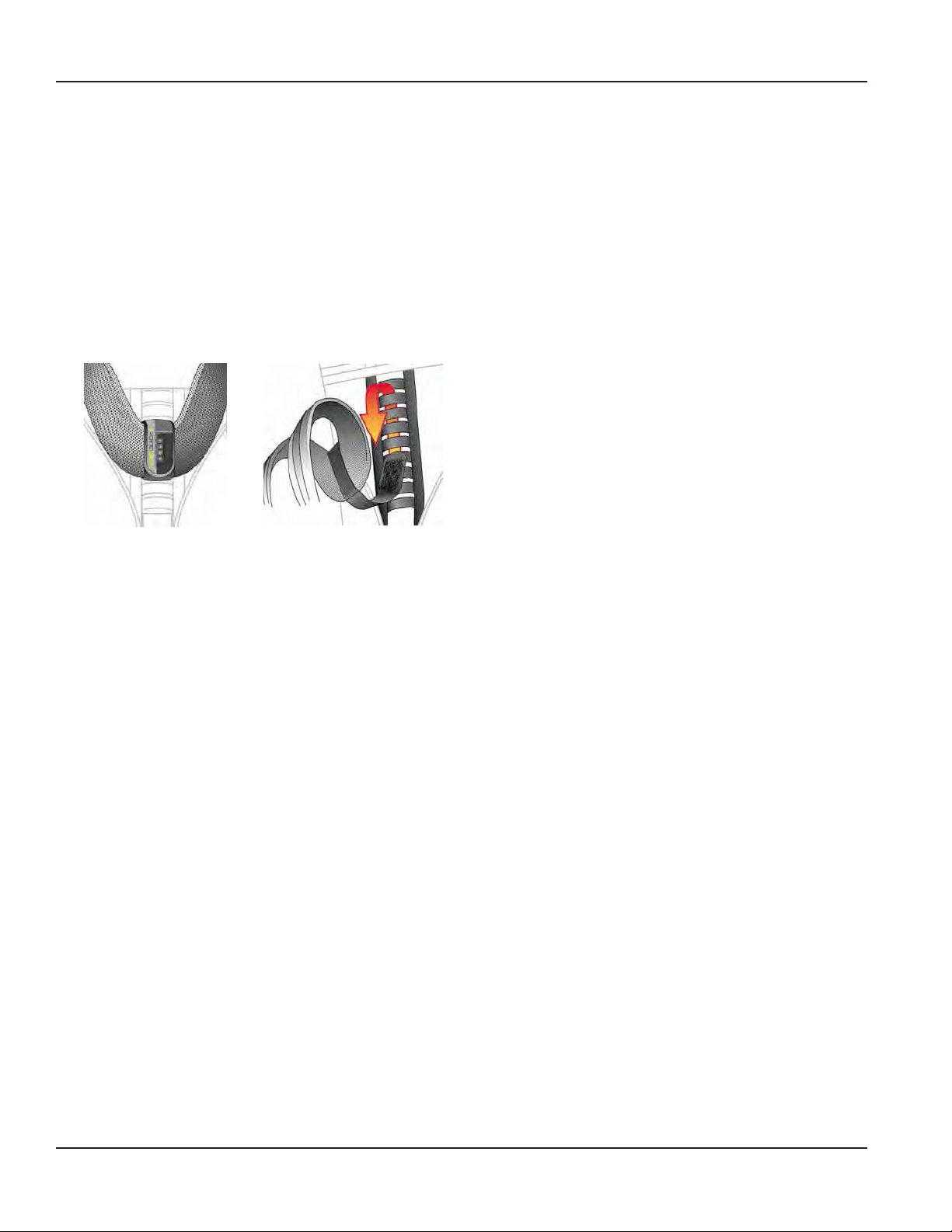
Frame
The adjustable frame allows you to position the straps to fit
your body.
1. Loosen and pull out the Velcro closure.
2. Put the harness strap into the right position, then lace the
straps through the 4 attachment loops. Tighten the strap
and secure the Velcro closure.
Hip Belt
Sternum Strap
Adjust the sternum strap as needed to a comfortable height
across your chest.
Buckle the sternum strap and tighten until the shoulder
straps are pulled inwards comfortably from your shoulders,
allowing your arms to move freely.
Pull the stabilizer straps located on either side of the hip
belt to snug the pack body toward the hip belt and stabilize
the load.
Final Tweaks
Pull the stabilizer straps, located on either side of the hip
belt, to snug the pack body toward the hip belt and stabilize
the load.
Go back to the shoulder straps and carefully take a bit of
tension off of them. This ensures the majority of the weight is
carried by your hips.
1. Loosen all of the straps on the harness system and
position the hip belt so the top of the iliac crest is about
1” down from the top of the hip belt. Correct positioning
will direct the weight onto your hips.
2. Put the pack on your back so that the hip belt is resting
over your hip bones.
3. Close the hip belt buckle and tighten it.
4. Check the padded sections of the hip belt to make sure
they wrap around your hips comfortably. Keep at least 1"
of clearance on either side of the center buckle.
Shoulder Straps
Pull down and back on the ends of the shoulder straps to
tighten them.
Shoulder straps should fit closely to hold the pack body
against your back, keeping the load forward. They should
NOT carry the weight.
Load Lifters
Load-lifter straps are located just below the tops of your
shoulders (near your collarbones) and should angle back
toward the pack body at a 45° angle.
Gently snug the load-lifter straps to pull weight off your
shoulders. (Overtightening the load lifters will cause a gap to
form between your shoulders and the shoulder straps.)
Page 6 March 2014
Page 7

User Manual
PREOPERATION CHECKS
Is Your Engine Ready to Go?
For your safety, and to maximize the service life of your
equipment, take a few minutes before you operate the
engine to check its condition. Take care of any problems you
fine, or have your servicing dealer correct them, before you
operate the engine.
IMPROPERLY MAINTAINING THE ENGINE, OR FAILURE
TO CORRECT A PROBLEM BEFORE OPERATION,CAN
CAUSE A MALFUNCTION IN WHICH YOU COULD BE
SERIOUSLY INJURED OR KILLED. ALWAYS PERFORM A PREOPERATION INSPECTION BEFORE EACH OPERATION AND
CORRECT ANY PROBLEM.
Before beginning your pre-operation checks, be sure the
engine is level and the engine switch is in the OFF position.
Always check the following items before you start the engine:
Check the General Condition of the Engine
1. Look around and underneath the engine for signs of oil or
gasoline leaks.
2. Remove any excessive dirt or debris, especially around
the muer and recoil starter.
3. Look for signs of damage.
4. Check that all shields and covers are in place, and all nuts,
bolts and screws are tightened.
Check the Engine
1. Check the fuel level (see “Refueling” on page11).
Starting with a full tank will help to eliminate or reduce
operating interruptions for refueling.
2. Check the engine oil level (see “Engine Oil” on page12).
Running the engine with a low oil level can cause engine
damage.
The Oil Alert system (applicable types) will automatically
stop the engine before the oil level falls below safe limits.
However, to avoid the inconvenience of an unexpected
shutdown, always check the engine oil level before
startup.
3. Check the air filter element (see “Air Cleaner” on
page13). A dirty air filter element will restrict air flow to
the carburetor, reducing engine performance.
4. Check the equipment powered by this engine.
Review the instructions provided with the equipment
powered by this engine for any precautions and procedures
that should be followed before engine startup.
Check the Throttle Lever
The throttle lever controls the speed of the engine. Push it
forward to increase the engine speed. Pull it back to decrease
the engine speed. The lever is an orange hand control
located on the left side of the backpack.
MPORTANTI
The engine will not start if the throttle lever is all the way back
in the OFF position. Push the lever forward about 1/2" into the
SLOW position to engage it.
OPERATION
Safe Operating Precautions
Before operating the engine for the first time, please review
the “Safety” on page5 and “Pre-Operation Checks” on
page7.
CARBON MONOXIDE GAS IS TOXIC. BREATHING IT CAN
CAUSE UNCONSCIOUSNESS AND EVEN DEATH. AVOID
ANY AREAS OR ACTIONS THAT EXPOSE YOU TO CARBON
MONOXIDE.
Vibrator Heads rotate at twice the speed of the engine and
are designed for nominal speeds of 12,000…13,000 RPM
(Engine speed of 6,000…6,500 RPM). Operating at excessive
speeds may reduce the performance or life of the product.
Starting the Engine
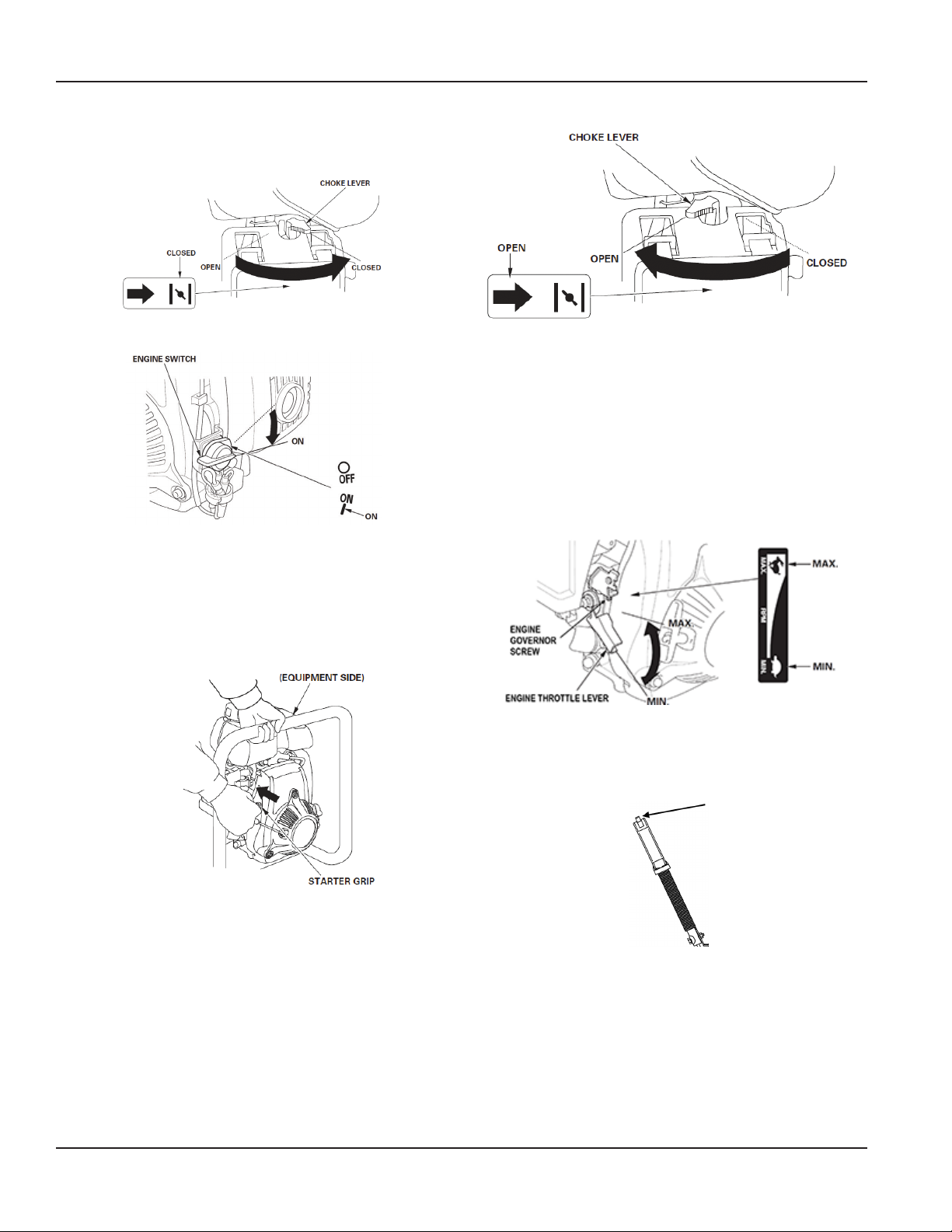
Move the fuel valve to the ON position.
Page 7 March 2014
Page 8
Concrete Vibrator, Backpack Model WBP50
To start a cold engine, move the choke lever to the CLOSED
position. To restart a warm engine, leave the choke lever in
the OPEN position.
Turn the engine switch to the ON position.
Setting the Engine Speed
Position the throttle lever for the desired engine speed.
Vibrator heads rotate at twice the speed of the engine and
are designed for nominal speeds of 12,000…13,000 RPM
(Engine speed of 6,000…6,500 RPM). Operating at excessive
speeds may reduce the performance or life of the product.
Maximum engine speed will change with the size of the
vibrator head and shaft. Use the engine governor screw to
adjust the throttle range within safe operational limits.
Set the throttle lever to the SLOW position. Pull the starter
grip lightly until you feel resistance, then pull briskly. Return
the starter grip gently.
OTE:N Do not allow the starter grip to snap back against
the engine. Return it gently to prevent damage to
the starter.
If the choke lever has been moved to the CLOSED position to
start the engine, gradually move it to the OPEN position as
the engine warms up.
MPORTANTI
The engine will not start if the throttle lever is all the way back
in the OFF position. Push the lever forward about 1/2” into the
SLOW position to engage it.
The engine throttle lever is controlled by the orange throttle
lever on the left side of the backpack. The throttle lever
should be set to SLOW for startup, FAST for operation, and
STOP for shutdown.
Page 8 March 2014
Page 9
User Manual
Using the Tachometer
The tachometer records engine hours and speed.
Press and release the tachometer button to toggle between
Hours, Tach and Service modes.
To view the number of engine starts: In Hours mode
(hourglass icon on left side of screen), hold down the button.
The screen will display the number of Engine Starts.
To view the maximum RPM display: On the RPM screen,
press and hold the button until Max 2RPM is displayed. This is
your Max RPM.
To clear the maximum RPM, continue to hold the button until
“00000” displays.
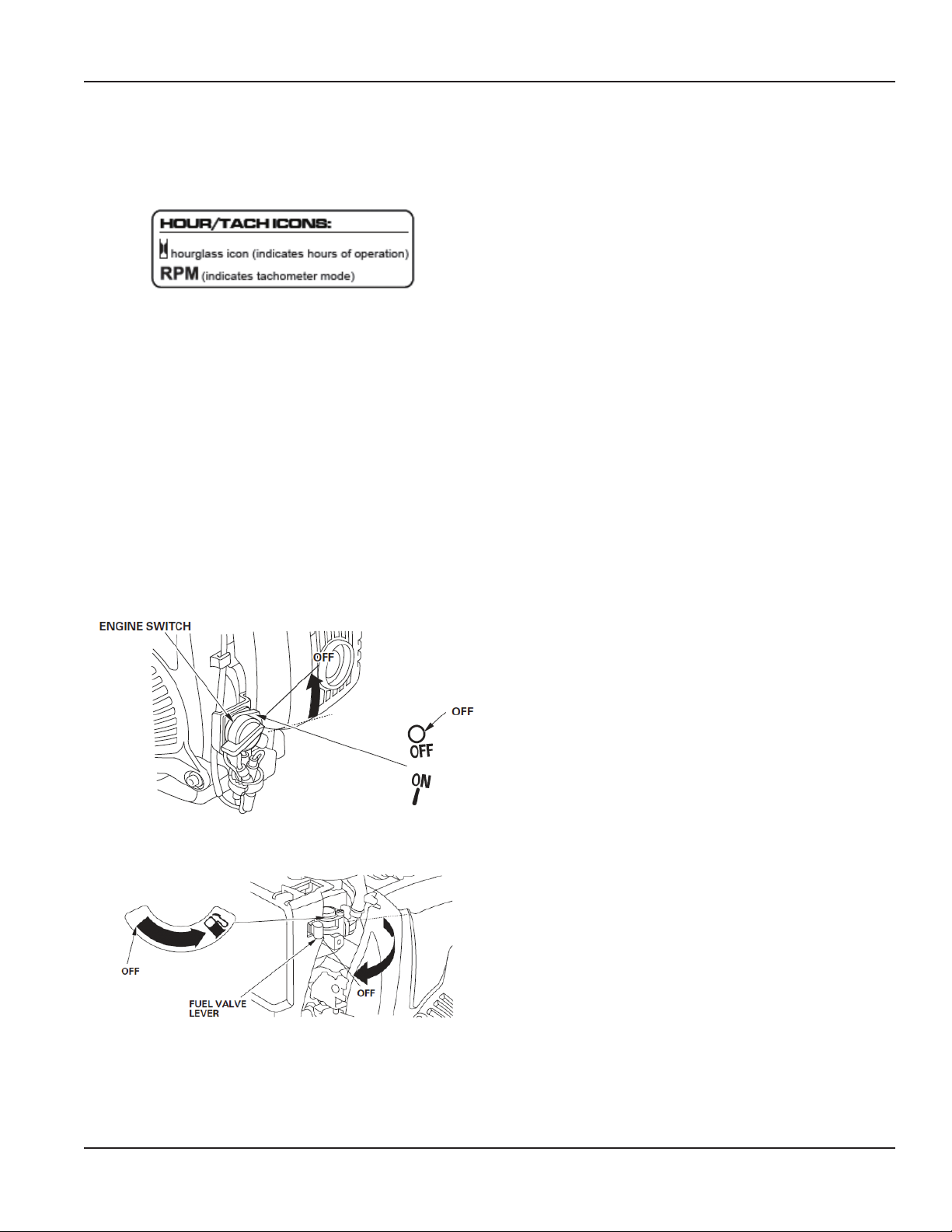
Stopping the Engine
To stop the engine in an emergency, simply turn the engine
switch to the OFF position. Under normal conditions, use the
following procedure.
1. Move the orange throttle lever to the STOP position.
2. Turn the engine switch to the OFF position.
3. Turn the fuel valve lever to the OFF position.
MAINTENANCE
Flex Shaft Grease
After each 50 hours of use, re-grease the flex shaft with Wyco
synthetic shaft grease #514B.
Vibrator Head Lubricant
If the vibrator head used is oil lubricated, after 50 hours of
use, change oil with Wyco lubricant #514-O.
Speed Increaser Servicing
After 250 hours of operation, the speed increaser assembly
should be disassembled, thoroughly cleaned and
reassembled with 1 ounce of Wyco gear oil SF 1000 (Wyco
part number W402151, 8 oz.) While disassembled, check
to see if the centrifugal clutch or the clutch drum need
replacing due to wear. A replacement clutch kit is available.
See drawing “W402316 Replacement Clutch Kit” on page23.
Use the Wyco drawings at the back of this manual as a
reference while assembling and disassembling.
1. Remove 4-1/4-28x3.0 long socket head cap screws (Wyco
part number W402629) and the split ring lock washers
(Wyco part number W402117) from the speed increaser
housing (Wyco part number W402601) that attach it to
the Honda GXH50 engine, and disconnect the speed
increaser housing from the motor.
2. Remove 4 #10-24x2.25 long socket head cap screws (Wyco
part number W402626) and the split ring lock washers
(Wyco part number W402XX) from the motor adapter
housing (Wyco part number W402153) and allow the gear
oil to drain from the gear housing.
3. Remove the gear oil plug (Wyco part number W402152),
the nylon washer (Wyco part number W402153) and allow
the gear oil to drain from the gear housing.
4. Clamp the speed increaser housing into a vise to secure it
while removing the internal components.
5. Hold the clutch drum (Wyco part number W402187) in
place using a chain or oil lter style strap wrench and
unscrew the hex driver on the opposite end using a 5/16"
allen wrench.
6. When the clutch drum is removed, it will allow for removal
of the bearing adapter retainer plate (Wyco part number
W402610). This plate lifts o and interfaces with an O-ring
(Wyco part number W402627). Remove the O-ring to
allow for removal of the input gear assembly (Wyco part
number W402615).
7. Tap on the internal gear through the plug hole on the
base of the speed increaser to loosen and remove the
input gear assembly.
8. Remove the snap ring (Wyco part number W402125) that
holds the output gear assembly in place and remove the
assembly from the housing.
Page 9 March 2014
Page 10

Concrete Vibrator, Backpack Model WBP50
9. Inspect the gear teeth and verify they are not worn.
Check the bearings to verify they are functional—turning
smoothly and freely. If either is worn, replace them both.
MPORTANTI
If EITHER the gear teeth OR the bearings are worn, replace
them BOTH at the same time with Wyco part numbers
W402615 and W402620.
10. Clean the internal surfaces of the gear increaser
housings, including the O-ring groove (Wyco part
numbers W402601, W402602, W402610 and W401612)
before reassembly.
11. Press the output gear assembly into place and install
the snap ring (Wyco part number W402125) in place to
prevent it from backing out.
12. Insert the input gear assembly into the cavity in the speed
increaser housing. You may need to use a 5/16" hex driver
to rotate the output shaft to align the gear before the
input gear assembly drops into the correct position.
13. Install a new O-ring (Wyco part number W402627) into
the groove around the bearing adapter.
14. Position the bearing adapter plate (Wyco part number
W402610) into the mating groove so it contacts the
bearing adapter (Wyco part number W402602).
15. Align the motor mounting bracket (Wyco part number
W402612) so the 4 holes for the #10-24 bolts align with
the threaded blind holes on the speed increaser housing
(Wyco part number W402601).
16. Apply Loctite 242 (or equivalent thread locker) onto the
threads of four #10-24x2.25L SHCS. Place the screws into
the clearance holes on the motor mounting bracket (Wyco
part number W402612) and torque to 25 in-lb.
17. Align the clutch drum (Wyco part number W402187) with
the mating threads on the input gear (Wyco part number
W402614) and apply 40 ft-lb of torque to tighten.
18. Put 2 ounces of gear oil (Wyco part number W402151)
into the gear increaser housing through the 1/428 bolt hole on the housing, opposite the motor
mounting bracket.
19. Install the 1/4" nylon washer (Wyco part number
W401253) and the 1/4-28x0.25 button cap screw (Wyco
part number W402152) and torque to 50 in-lb.
20. Align the motor bracket geometry with that on the
Honda GXH50 engine. Apply Loctite 242 or equivalent
onto the bolt threads and slide four 1/4" lock washers
(Wyco part number W402117) onto the bolts. Insert four
1/4-28x3.00 long alloy steel bolts (Wyco part number
W402629) into the clearance holes, and torque to 10 ft-lb.
Honda Engine GXH50
Follow the recommendations in the Honda engine Owner’s
Manual for their GXH50 engine regarding, but not limited to,
the spark plug and air filter service.
SERVICING THE ENGINE
The Importance of Maintenance
Good maintenance is essential for safe, economical and
trouble-free operation. It also helps reduce pollution.
IMPROPER MAINTENANCE, OR FAILURE TO CORRECT
A PROBLEM BEFORE OPERATION, CAN CAUSE A
MALFUNCTION IN WHICH YOU CAN BE SERIOUSLY HURT
OR KILLED.
ALWAYS FOLLOW THE INSPECTION AND MAINTENANCE
RECOMMENDATIONS AND SCHEDULES IN THIS MANUAL.
To help you properly care for your engine, the following
pages include a maintenance schedule, routine inspection
procedures, and simple maintenance procedures using
basic hand tools. Other service tasks that are more difficult,
or require special tools, are best handled by professionals
and are normally performed by a Honda technician or other
qualified mechanic.
The maintenance schedule applies to normal operating
conditions. If you operate your engine under severe
conditions, such as sustained high-load or high-temperature
operation, or use in unusually wet or dusty conditions,
consult your servicing dealer for recommendations
applicable to your individual needs and use.
Maintenance, replacement, or repair of the emission control
devices and systems may be performed by any engine repair
establishment or individual, using parts that are ‘‘certified’’ to
EPA standards.
Maintenance Safety
Some of the most important safety precautions follow.
However, we cannot warn you of every conceivable hazard
that can arise in performing maintenance. Only you can
decide whether or not you should perform a given task.
Good maintenance is essential for safe, economical and
trouble-free operation. It also helps reduce pollution.
FAILURE TO PROPERLY FOLLOW MAINTENANCE
INSTRUCTIONS AND PRECAUTIONS CAN CAUSE YOU TO
BE SERIOUSLY HURT OR KILLED. ALWAYS FOLLOW THE
PROCEDURES AND PRECAUTIONS IN THIS MANUAL.
Safety Precautions
• Make sure the engine is off before you begin any
maintenance or repairs. This will eliminate several
potential hazards:
Page 10 March 2014
Page 11
User Manual
◊ Carbon monoxide poisoning from engine exhaust.
Operate outside away from open windows or doors.
◊ Burns from hot parts.
Let the engine and exhaust system cool
before touching.
◊ Injury from moving parts.
Do not run the engine unless instructed to do so.
• Read the instructions before you begin, and make sure
you have the tools and skills required.
• To reduce the possibility of fire or explosion, be careful
when working around gasoline. Use only a nonflammable solvent, not gasoline, to clean parts. Keep
cigarettes, sparks and flames away from all
fuel-related parts.
Remember that an authorized Honda servicing dealer knows
your engine best and is fully equipped to maintain and
repair it.
To ensure the best quality and reliability, use only new
genuine Honda parts or their equivalents for repair
and replacement.
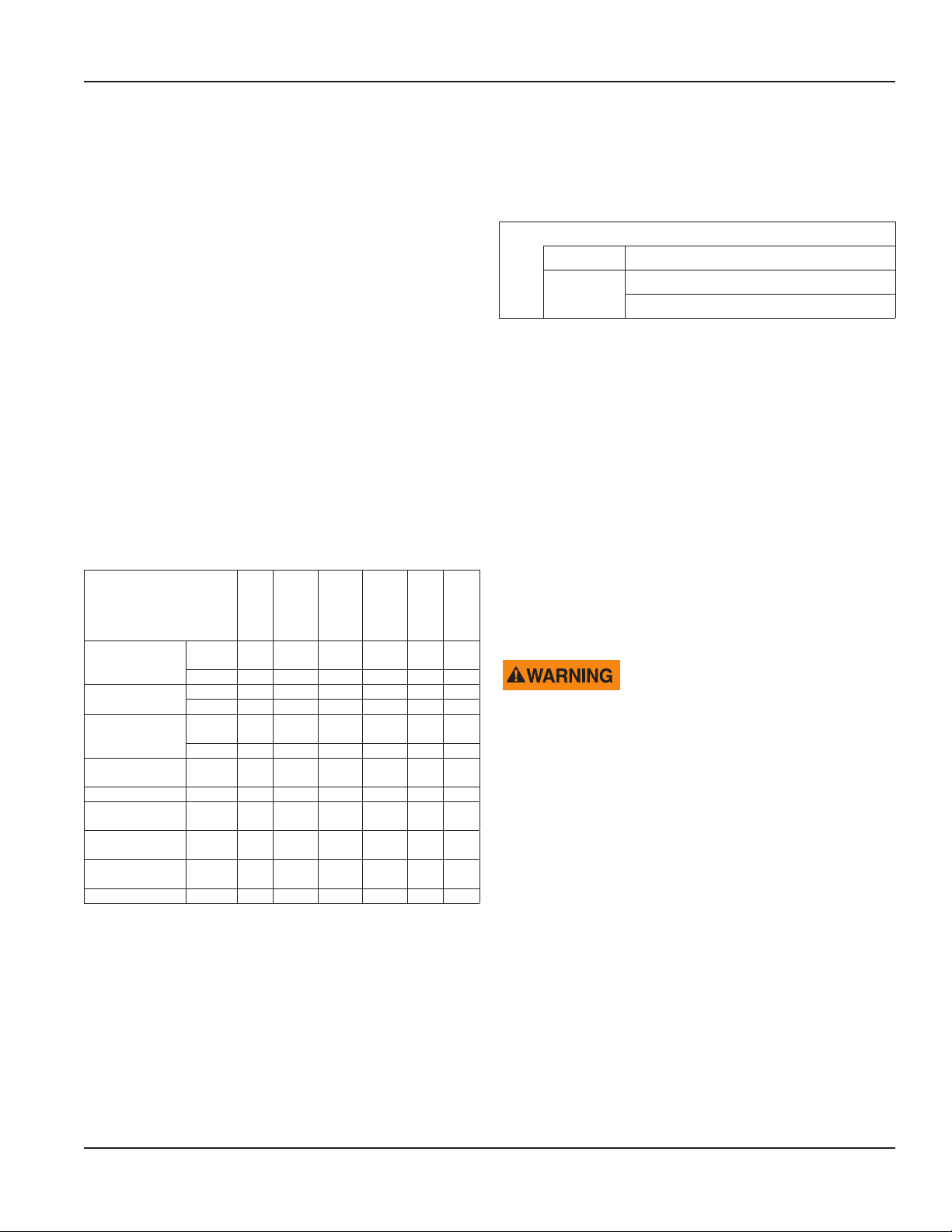
Maintenance Schedule
Regular Service Period (1)
Perform at every indicated
month or operating hour
interval, whichever comes first.
Check
Engine oil
Air filter
Spark plug
Spark arrester
(applicable types)
Fuel tank and filter Clean X (4)
* Idle speed
* Valve clearance
*Combustion
chamber
* Fuel tube Check
level
Change X (3)
Check X
Clean X (2)
Check,
adjust
Replace X
Clean X
Check,
adjust
Check,
adjust
Clean X (4)
Each
use
X
First
month
or 10 hr
Every 3
months
or 25 hr
Every 6
months
or 50 hr
* See the Honda Owner’s Manual.
(1) For commercial use, log hours of operation to determine
proper maintenance intervals.
(2) Service more frequently when used in dusty areas.
(3) Change engine oil every 25 hours when used under heavy
load or in high ambient temperatures.
(4) These items should be serviced by your Honda
servicing dealer, unless you have the proper tools and are
mechanically proficient. See the Honda Owner’s Manual for
service procedures.
Every
year
or 100
hr
X
X (4)
Every
2
years
or 300
hr
Failure to follow this maintenance schedule could result in
non- warrantable failures.
Refueling
Recommended Fuel
Unleaded gasoline
U.S. Pump octane rating 86 or higher
Except
U.S.
This engine is certified to operate on unleaded gasoline with
a pump octane rating of 86 or higher (a research octane
rating of 91 or higher).
Refuel in a well-ventilated area with the engine stopped.
If the engine has been running, allow it to cool first. Never
refuel the engine inside a building where gasoline fumes
may reach flames or sparks.
You may use regular unleaded gasoline containing no
more than 10% Ethanol (E10) or 5% Methanol by volume.
In addition, Methanol must contain co-solvents and
corrosion inhibitors. Use of fuels with content of Ethanol
or Methanol greater than shown above may cause starting
and/or performance problems. It may also damage metal,
rubber, and plastic parts of the fuel system. Engine damage
or performance problems that result from using a fuel with
percentages of Ethanol or Methanol greater than shown
above are not covered under the warranty.
GASOLINE IS HIGHLY FLAMMABLE AND EXPLOSIVE, AND
YOU CAN BE BURNED OR SERIOUSLY INJURED WHEN
REFUELING.
• STOP ENGINE AND KEEP HEAT, SPARKS, AND FLAME
AWAY.
• REFUEL ONLY OUTDOORS.
• WIPE UP SPILLS IMMEDIATELY.
OTE:N Fuel can damage paint and some types of plastic. Be
careful not to spill fuel when filling your fuel tank.
Damage caused by spilled fuel is not covered under
the Distributor’s Limited Warranty. Move at least 1
meter (39 inches) away from the fueling source and
site before starting the engine.
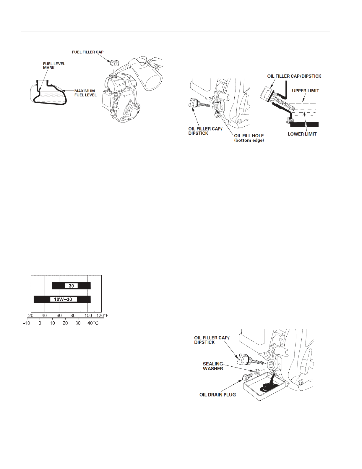
1. With the engine stopped and on a level surface, remove
the fuel ller cap and check the fuel level. Rell the tank if
the fuel level is low.
2. Add fuel to the bottom of the fuel level mark of the fuel
tank. Do not overll. Wipe up spilled fuel before starting
the engine.
Research octane rating 91 or higher
Pump octane rating 86 or higher
Page 11 March 2014
Page 12
Concrete Vibrator, Backpack Model WBP50
3. Refuel carefully to avoid spilling fuel. Do not ll the fuel
tank completely. It may be necessary to lower the fuel
level depending on operating conditions. After refueling,
tighten the fuel ller cap securely.
Keep gasoline away from appliance pilot lights, barbecues,
electric appliances, power tools, and anything else that may
generate a spark. Spilled fuel is a fire hazard and causes
environmental damage. Wipe up spills immediately.
Engine Oil
Oil is a major factor affecting performance and service life.
Use a 4-stroke automotive detergent oil. Use a funnel with a
long spout to add oil.
Recommended Oil
Use 4-stroke motor oil that meets or exceeds the
requirements for API service category SJ or later (or
equivalent). Always check the API service label on the
oil container to be sure it includes the letters SJ or later
(or equivalent).
“Recommended Oil” on page12) to the upper limit mark
on the bottom edge of the oil ll hole. Do not overll.
4. Reinstall the oil ller cap/dipstick.
OTE:N Running the engine with a low oil level can cause
engine damage. This type of damage is not covered
by the Distributor’s Limited Warranty.
The Oil Alert system (applicable types) will automatically
stop the engine before the oil level falls below the safe limit.
However, to avoid the inconvenience of an unexpected
shutdown, always check the engine oil level before startup.
Oil Change
Drain the used oil when the engine is warm. Warm oil drains
quickly and completely. Use a funnel with a long spout to
add oil.
1. Place a suitable container below the engine to catch the
used oil, then remove the oil ller cap/dipstick, oil drain
plug and washer.
2. Allow the used oil to drain completely, then reinstall the
oil drain plug and new washer, and tighten the oil drain
plug securely.
Please dispose of used motor oil in a manner that is
compatible with the environment. We suggest you take used
oil in a sealed container to your local recycling center or
service station for reclamation. Do not throw it in the trash,
pour it on the ground, or pour it down a drain.
SAE 10W-30 is recommended for general use. Other
viscosities shown in the chart may be used when the average
temperature in your area is within the indicated range.
Oil Level Check
Check the engine oil level with the engine stopped and in a
level position.
1. Remove the oil ller cap/dipstick and wipe it clean.
2. Insert the oil ller cap/dipstick into the oil ller neck as
shown, but do not screw it in, then remove it to check the
oil level
3. If the oil level is near or below the lower limit mark
on the dipstick, ll with the recommended oil (see
Page 12 March 2014
3. With the engine in a level position, ll with the
recommended oil (see “Recommended Oil” on page12)
to the upper limit mark (bottom edge of the oil ll hole.
Page 13
OTE:N Running the engine with a low oil level can cause
engine damage. This type of damage is not covered
by the Distributor’s Limited Warranty.
4. Reinstall the oil ller cap/dipstick securely.
Air Cleaner
A dirty air cleaner will restrict air flow to the carburetor,
reducing engine performance. If you operate the engine in
very dusty areas, clean the air filter more often than specified
in the “Maintenance Schedule” on page11.
OTE:N Operating the engine without an air filter, or with a
damaged air filter, will allow dirt to enter the engine,
causing rapid engine wear. This type of damage is
not covered by the Distributor’s Limited Warranty.
User Manual
Spark Plug
Recommended Spark Plugs: CR5HSB (NGK) U16FSR-UB
(DENSO) SCHEDULE.
OTE:N An incorrect spark plug can cause engine damage.
For good performance, the spark plug must be properly
gapped and free of deposits.
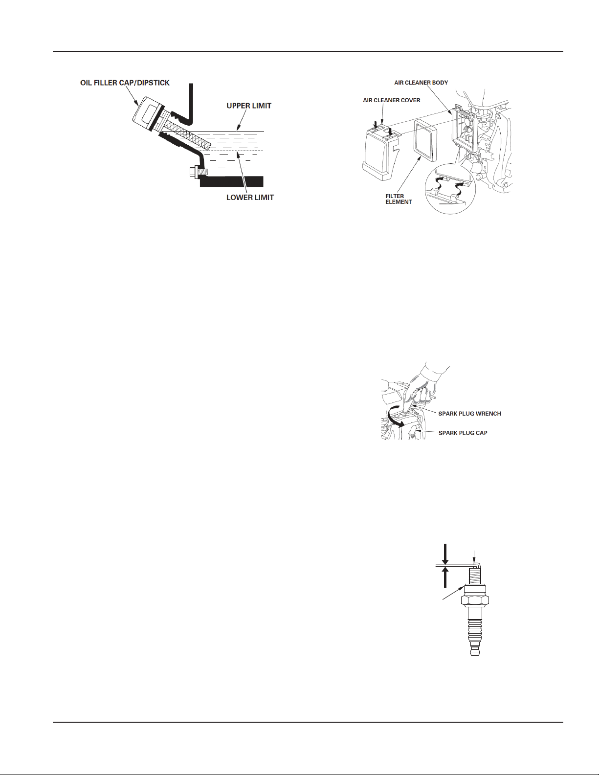
1. Disconnect the spark plug cap and remove any dirt from
round the spark plug area.
2. Remove the spark plug with a 5/8" spark plug wrench.
Inspection
Remove the air cleaner cover and inspect the filter element.
Clean or replace a dirty filter element. Always replace a
damaged filter element.
Cleaning
1. Clean the lter element in warm soapy water, rinse, and
allow to dry thoroughly. Or clean the lter element in a
non-ammable solvent and allow to dry.
2. Dip the lter element in clean engine oil, then squeeze
out all excess oil. The engine will smoke when started if
too much oil is left in the element.
3. Wipe dirt from the air cleaner body and cover, using
a moist rag. Be careful to prevent dirt from entering
the carburetor.
3. Inspect the spark plug. Replace it if it is damaged or badly
fouled, if the sealing washer is in poor condition, or if the
electrode is worn.
4. Measure the spark plug electrode gap with a wiretype feeler gauge. Correct the gap, if necessary, by
carefully bending the side electrode. The gap should be
0.024…0.028" (0.60…0.70 mm).
Side electrode
0.60 . . . 0.70 mm
(0.024 . . . 0.028 in.)
Sealing washer
5. Install the spark plug carefully, by hand, to avoid
cross-threading.
Page 13 March 2014
Page 14
Concrete Vibrator, Backpack Model WBP50
6. After the spark plug is seated, tighten with a 5/8" spark
plug wrench to compress the sealing washer.
7. When installing a new spark plug, tighten 1/2 turn after
the spark plug seats to compress the washer.
8. When reinstalling the original spark plug, tighten 1/8
to 1/4 turn after the spark plug seats to compress
the washer.
OTE:N A loose spark plug can overheat and damage the
engine. Overtightening the spark plug can damage
the threads in the cylinder head.
9. Attach the spark plug cap to the spark plug.
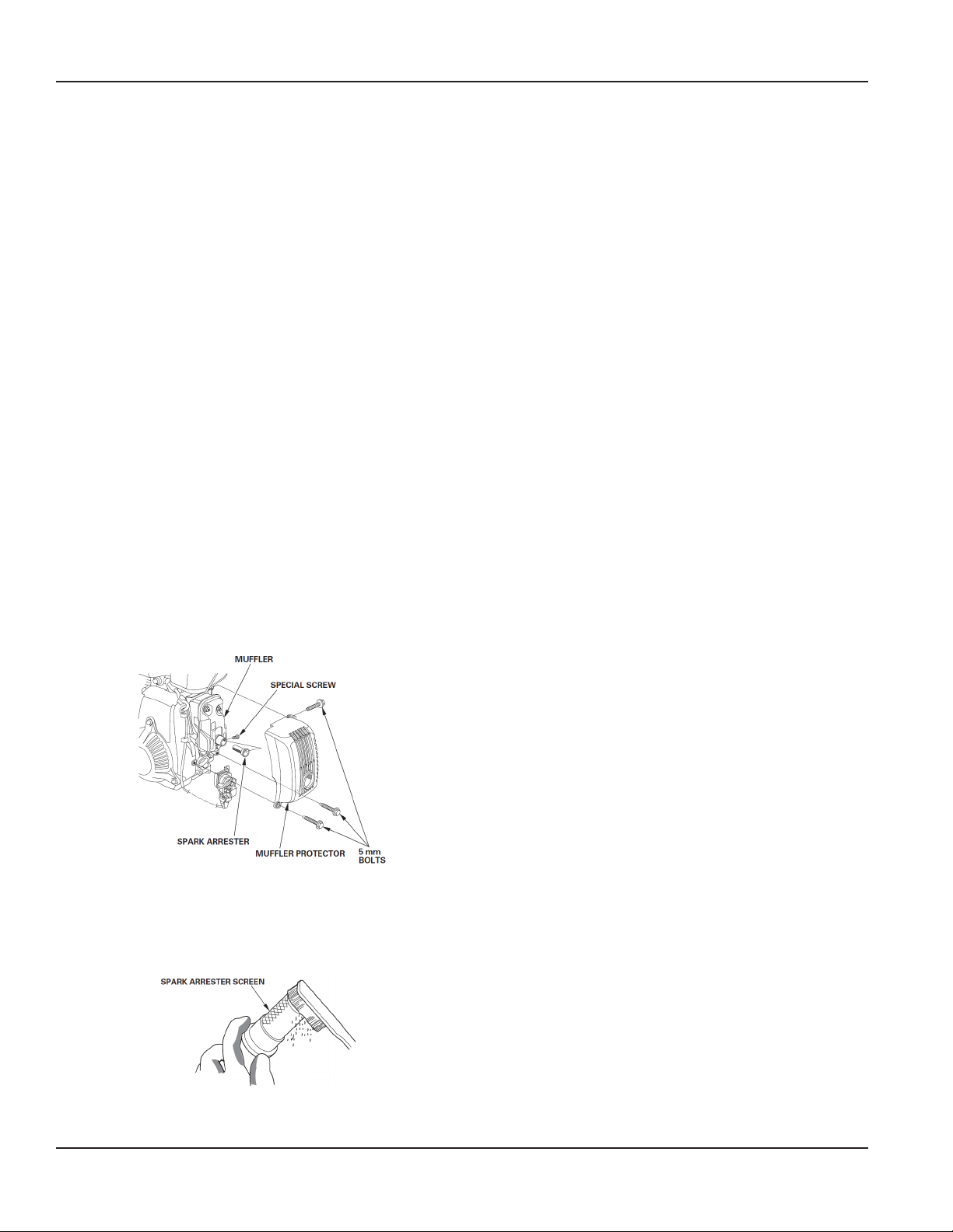
Spark Arrester (Optional Equipment)
Your engine is not factory-equipped with a spark arrester. In
some areas, it is illegal to operate an engine without a spark
arrester. Check local laws and regulations. A spark arrester is
available from authorized Honda servicing dealers.
The spark arrester must be serviced every 100 hours to keep
it functioning as designed.
If the engine has been running, the muffler will be hot. Allow
it to cool before servicing the spark arrester.
Spark Arrester Removal
1. Remove the three 5 mm bolts from the muer protector
and remove the muer protector.
2. Remove the special screw from the spark arrester, and
remove the spark arrester from the muer.
Spark Arrester Cleaning and Inspection
1. Use a brush to remove carbon deposits from the spark
arrester screen. Be careful not to damage the screen.
Replace the spark arrester if it has breaks or holes.
HELPFUL TIPS AND SUGGESTIONS
Storing Your Engine
Engine Storage Preparation
Proper storage preparation is essential for keeping your
engine trouble-free and looking good . The following steps
will help to keep rust and corrosion from impairing your
engine’s function and appearance, and will make the engine
easier to start when you use it again.
Engine Cleaning
If the engine has been running, allow it to cool for at least
half an hour before cleaning. Clean all exterior surfaces,
touch up any damaged paint, and coat other areas that may
rust with a light film of oil.
OTE:N Using a garden hose or pressure washing equipment
can force water into the air cleaner or muffler
opening. Water in the air cleaner will soak the air
filter, and water that passes through the air filter or
muffler can enter the cylinder, causing damage.
Engine Fuel
Gasoline will oxidize and deteriorate in storage. Deteriorated
gasoline will cause hard starting, and it leaves gum deposits
that clog the fuel system. If the gasoline in your engine
deteriorates during storage, you may need to have the
carburetor and other fuel system components serviced
or replaced.
The length of time that gasoline can be left in your fuel
tank and carburetor without causing functional problems
will vary with such factors as gasoline blend, your storage
temperatures, and whether the fuel tank is partially or
completely filled. The air in a partially filled fuel tank
promotes fuel deterioration. Very warm storage temperatures
accelerate fuel deterioration. Fuel deterioration problems
may occur within a few months, or even less if the gasoline
was not fresh when you filled the fuel tank.
Fuel system damage or engine performance problems
resulting from neglected storage preparation are not covered
under the Distributor ’s Limited Warranty.
You can extend fuel storage life by adding a gasoline
stabilizer that is formulated for that purpose, or you can
avoid fuel deterioration problems by draining the fuel tank
and carburetor.
Adding a Gasoline Stabilizer to Extend Fuel Storage Life
When adding a gasoline stabilizer, fill the fuel tank with fresh
gasoline. If only partially filled, air in the tank will promote
fuel deterioration during storage. If you keep a container
of gasoline for refueling, be sure that it contains only
fresh gasoline.
2. Install the spark arrester and muer protector in the
reverse order of disassembly.
Page 14 March 2014
1. Add gasoline stabilizer following the
manufacturer’s instructions.
Page 15
2. After adding a gasoline stabilizer, run the engine
outdoors for 10 minutes to be sure that treated gasoline
has replaced the untreated gasoline in the carburetor.
3. Stop the engine, and move the fuel valve lever to the
OFF position.
Draining the Fuel Tank and Carburetor
GASOLINE IS HIGHLY FLAMMABLE AND EXPLOSIVE, AND
YOU CAN BE BURNED OR SERIOUSLY INJURED WHEN
HANDLING FUEL.
• STOP ENGINE AND KEEP HEAT, SPARKS, AND FLAME
AWAY.
• HANDLE FUEL ONLY OUTDOORS.
• WIPE UP SPILLS IMMEDIATELY.
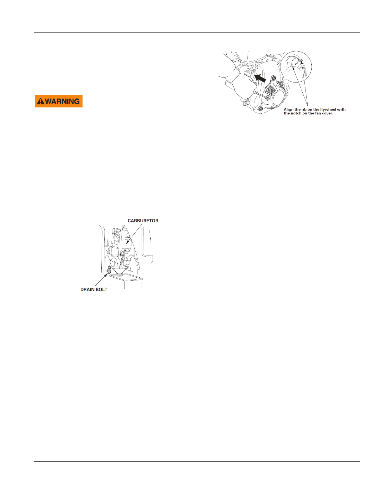
1. Place an approved gasoline container below the
carburetor, and use a funnel to avoid spilling fuel.
2. Drain the fuel tank and carburetor.
Remove the carburetor drain bolt, then move the fuel
valve to the ON position.
User Manual
Storage Precautions
If your engine will be stored with gasoline in the fuel tank
and carburetor, it is important to reduce the hazard of
gasoline vapor ignition. Select a well-ventilated storage area
away from any appliance that operates with a flame, such as
a furnace, water heater, or clothes dryer. Also avoid any area
with a spark-producing electric motor, or where power tools
are operated.
If possible, avoid storage areas with high humidity, because
that promotes rust and corrosion.
Keep the engine level in storage. Tilting can cause fuel or
oil leakage.
With the engine and exhaust system cool, cover the engine
to keep out dust. A hot engine and exhaust system can
ignite or melt some materials. Do not use sheet plastic as a
dust cover.
A nonporous cover will trap moisture around the engine,
promoting rust and corrosion.
3. After all the fuel has drained into the container, reinstall
the drain bolt (carburetor equipped with a drain bolt type
only). Tighten the drain bolt or drain screw securely.
Engine Oil
Change the engine oil (see “Engine Oil” on page12).
Engine Cylinder
1. Remove the spark plug (see “Spark Plug” on page13).
2. Pour a tablespoon 5…10 cm3 (5…10 cc) of clean engine
oil into the cylinder.
3. Pull the starter grip several times to distribute the oil in
the cylinder.
4. Reinstall the spark plug.
5. Pull the starter grip slowly until resistance is felt and the
rib on the ywheel aligns with the notch on the fan cover.
This will close the valves so moisture cannot enter the
engine cylinder. Return the starter grip gently.
Removal from Storage
Check your engine as described in “Is Your Engine Ready to
Go?” on page7.
If the fuel was drained during storage preparation, fill the
tank with fresh gasoline. If you keep a container of gasoline
for refueling, be sure it contains only fresh gasoline. Gasoline
oxidizes and deteriorates over time, causing hard starting.
If the cylinder was coated with oil during storage
preparation, the engine will smoke briefly at startup. This
is normal.
Transporting
If the engine has been running, allow it to cool for at least 15
minutes before loading the engine-powered equipment on
the transport vehicle. A hot engine and exhaust system can
burn you and can ignite some materials.
Keep the engine level when transporting to reduce the
possibility of fuel leakage. Turn the fuel valve to the OFF
position (see “Pre-Operation Checks” on page7).
Page 15 March 2014
Page 16

Concrete Vibrator, Backpack Model WBP50
TROUBLESHOOTING
Engine Will Not Start Possible Cause Correction
Check control
positions.
Check engine oil level. Engine oil level low (Oil
Check throttle wire. Throttle wire nipple is
Check throttle position Throttle is in STOP
Check fuel. Out of fuel. Refuel. See “Refueling”
Remove and inspect
spark plug.
Take engine to an
authorized Honda
servicing dealer, or
refer to the Owner’s
Manual.
Fuel valve OFF. Move lever to ON
Choke open. Move lever to CLOSED
Engine switch OFF. Turn engine switch to
Alert stops engine).
not engaged.
position
Bad fuel; engine stored
without treating or
draining gasoline,
or refueled with bad
gasoline.
Spark plug faulty,
fouled, or improperly
gapped.
Spark plug wet with
fuel (flooded engine.)
Fuel filter restricted,
carburetor
malfunction, ignition
malfunction, valves
stuck.
position.
position unless the
engine is warm.
ON position.
Fill with the
recommended oil
to the proper level.
See “Engine Oil” on
page12.
Verify that the throttle
wire is engaged. See
“Check the Throttle
Lever” on page7.
Move throttle to SLOW
position. See “Setting
the Engine Speed” on
page8.
on page11.
Drain fuel tank and
carburetor. See
“Draining the Fuel
Tank and Carburetor”
on page15. Refuel
with fresh gasoline.
See “Refueling” on
page11.
Gap or replace spark
plug. See “Spark Plug”
on page13.
Dry and reinstall
the spark plug. Start
the engine with the
throttle lever in the
MAX. position.
Replace or repair faulty
components.
Engine Lacks
Power
Check air filter. Filter element
Check fuel. Bad fuel; engine
Take engine to
an authorized
Honda
servicing
dealer, or refer
to the Owner’s
Manual.
Check engine
governor screw
Possible Cause Correction
restricted.
stored without
treating or draining
gasoline, or refueled
with bad gasoline.
Fuel filter restricted,
carburetor
malfunction, ignition
malfunction, valves
stuck.
Throttle cannot fully
open
Clean or replace filter element.
See “Air Cleaner” on page13.
Drain fuel tank and carburetor.
See “Draining the Fuel Tank
and Carburetor” on page15.
Refuel with fresh gasoline. See
“Refueling” on page11.
Replace or repair faulty
components.
Back off the engine governor
screw. See “Setting the Engine
Speed” on page8.
SERVICE
Repair or replacement parts can be ordered from Wyco
Tool. Warranty repairs or chargeable repairs can be made
by sending the product to the following address. Always
obtain an RA number (Return Authorization) and include
it in the address before returning any parts for warranty
consideration or chargeable repair.
Phone: (262) 639-6770 or Toll free: (800) 233-9926
RA#
Wyco Tool
8635 Washington Avenue
Racine, Wisconsin 53406-3738
Engine parts may be obtained from your local Honda engine
dealer found at www.engines.honda.com or Honda Customer
Relations at 770-497-6400.
PARTS
Honda Engine Parts
When Wyco part numbers are listed, the parts are available
directly from Wyco.
Honda Engine Warranty
Go to http://engines.honda.com/parts-and-support/warranty-
info
Wyco Warranty
Go to http://wycotool.com/manuals
Wyco Drawings
Description Drawing #
Backpack assembly W402535
Frame assembly W402530
Speed increaser assembly W402600
Replacement clutch kit W402316
Quick disconnect adapter W402630
Page 16 March 2014
Page 17
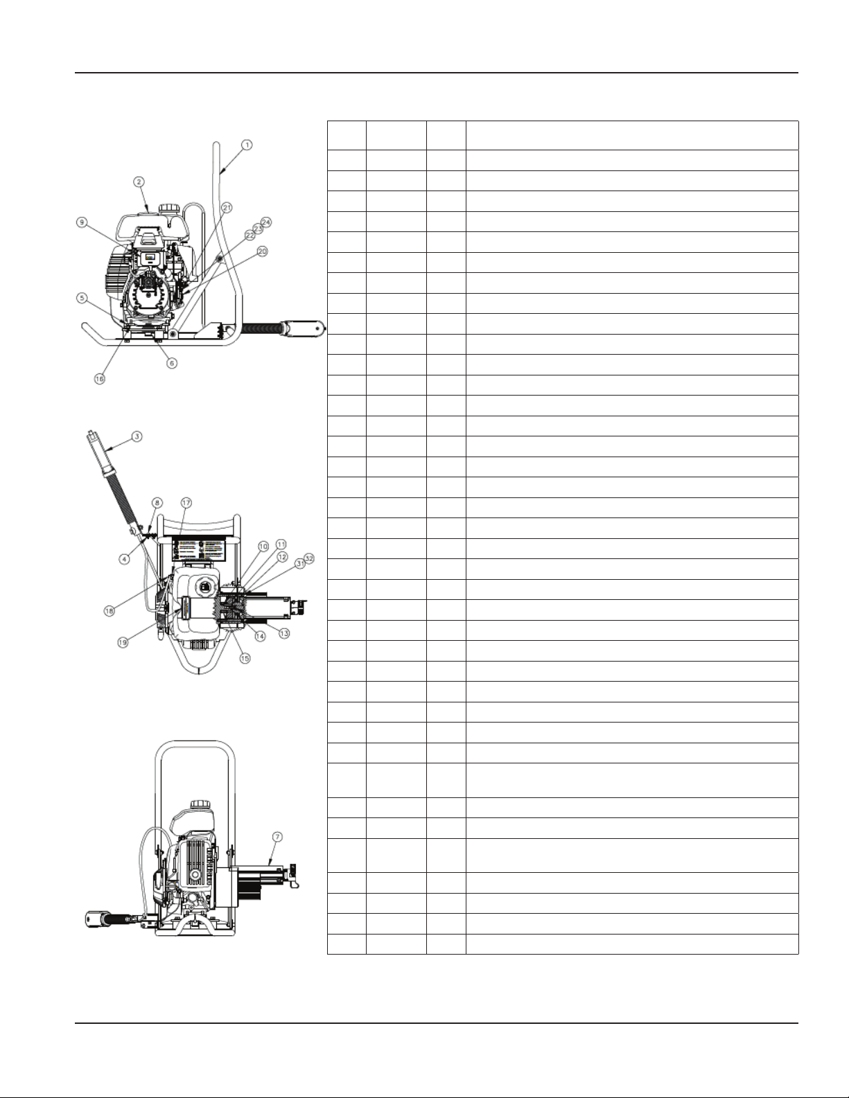
W402535 Backpack Assembly
Item
1 4025630 1 Frame, steel, backpack, Honda; assembly
2 402304 1 Engine, Honda; 50 cc 2.5 hp
3 402307 1 Backpack, echo throttle control
4 402306 3 Backpack, motor mount, locknut; #10-24
5 402531 1 Assembly, bracket, Honda engine, backpack weld
6 402526 6 Screw, HHCS, 5/16-18 x 5/8; GR 9
7 883126 6 Washer, lock, 5/16; zinc plated
8 402111 3 Isolator, rubber; backpack
9 402178 1 Bearing, oil impreg, flange, bronze
10 402109 1 Ring, retaining, external
11 402600 1 Speed increaser assy, gas backpack, Honda
12 402313 3
13 402154 1
14 402315 2
15 402316 1
16 402317 1
17 402318 1 Screw, socket head cap, 1/4-28 x 1/2" long
18 402168 1 Washer, flat, clutch
19 402319 1 Collar, shaft; Honda backpack
20 402320 4 Screw, flat socket head cap, M6 x 16 mm long
21 402324 1 Backpack motor mount screw; #10-32 x 3/8" long
22 402322 1 Clamp, throttle cable, Honda backpack
23 402534 1 Plate, mounting, isolator; backpack
24 402150 1 Decal, caution; backpack engine
25 402323 1 Backpack, Honda; caution label
26 402325 1 Backpack, Honda; throttle spring plate
27 402525 1 Grounding screw, SEMS #10-32 x 3/8” long
28 402326 1 Backpack, Honda; throttle spring
29 402523 1 Backpack, Honda; throttle/governor lever
30 * 402327 1 Backpack, Honda; throttle swivel (mounted to item 29)
31 * 402524 1
32 * 402181 3 Tie cable, mini, 4" x 0.100"
33 * 402522 6 in. Silicone coated fiberglass sleeving, 0.085" ID, 100' roll
34 * 402521 1
35 * 402520 6 in.
36 * 402519 6 in.
37 * 402184 1
38 * 402185 1
* Parts not shown.
Part
Number
Qty Description
Backpack throttle mount screw, #10-24 x 1/2" long
Meter, RPM/Hour with mounting screws
Screw, set, 1/4-20; knurled cup point
Assembly, clutch, Honda backpack
Key, square; 3/16 x 0.875" long
Washer, throttle,13/64 ID, 7/16 OS, 0.03…0.07 thick, zinc
plated steel (used with item 29)
Connector, bullet, 16-14 AWG, blue 0.156"; 0.178"; 1.00 in OAL,
fully insulated, crimp terminal
Heat shrink tubing, 3/8" expanded, 1/4" recovered
Spiral wrap, 3/8" diameter
Backpack; Ergopack decal
Nameplate, Ergopack
User Manual
Page 17 March 2014
Page 18
Concrete Vibrator, Backpack Model WBP50
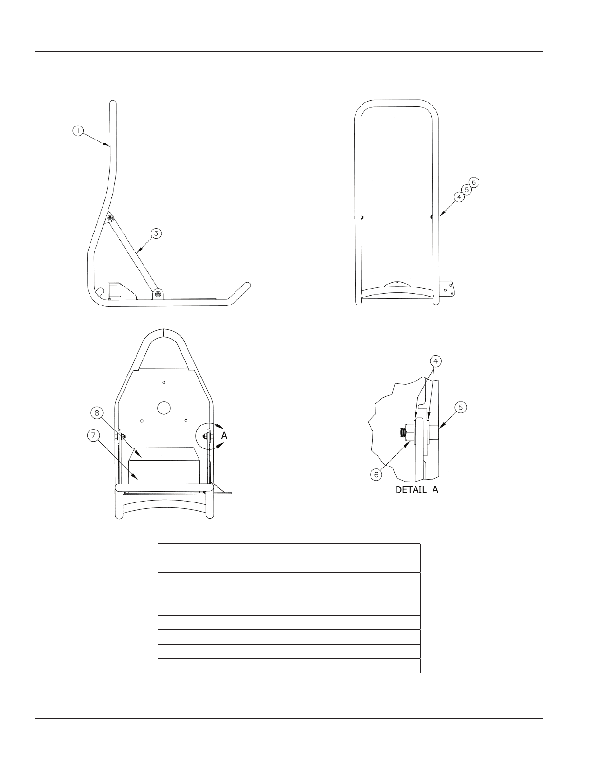
W402530 Frame Assembly
Item Part Number Qty Description
1 W402513 1 Frame, weldment; backpack; Honda
2 W402302 1 Backpack frame Deuter (not shown)
3 W402532 2 Brace; frame; backpack
4 W402527 8 Washer, flat, zinc plated, 1/4"
5 W402528 4 Screw, socket head, Nyloc, 1/4-20
6 W402529 4 Nut, zinc plated, 1/4-20
7 W402150 1 Decal, caution, backpack engine
8 W402184 1 Backpack, Ergopack
Page 18 March 2014
Page 19
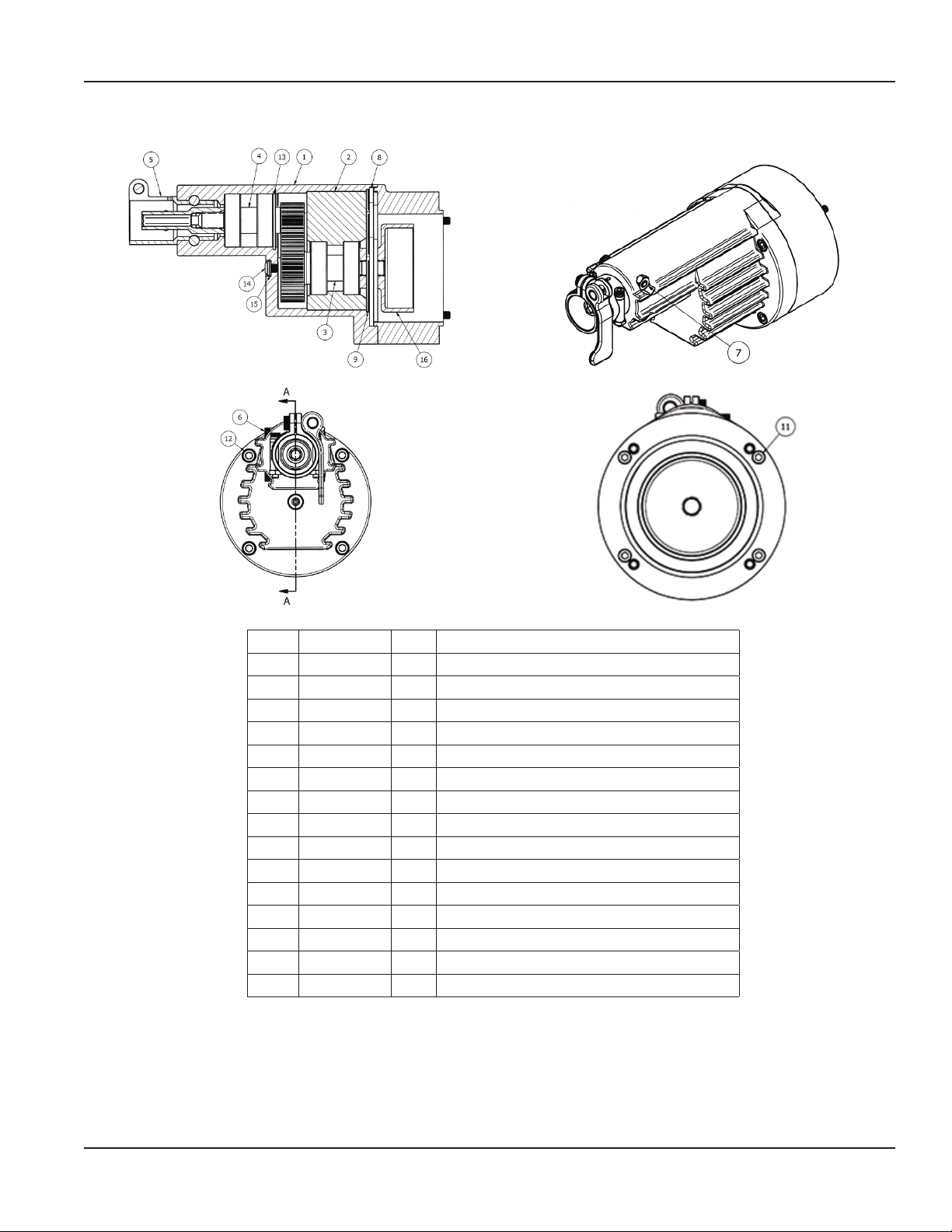
W402600 Speed Increaser Assembly, 1 of 4
User Manual
Item Part Number Qty Description
1 W402601 1 Housing, speed increaser; machined
2 W402602 1 Bearing adapter; speed increaser
3 W402615 1 Gear assembly, input; speed increaser
4 W402620 1 Gear assembly, output; speed increaser
5 W402607 1 Q.D. connector; speed increaser; Honda
6 W402625 2 Shoulder screw; hex head self-locking; 1/4"-20
7 W402626 2 Hex nut; black oxide; grade 5; 1/4"-20
8 W402610 1 Plate, bearing adapter retainer
9 W402627 1 O-ring, seal, speed increaser
11 W402628 4 Screw, socket head cap; #10-24 x 2-1/4" long; Z.P.
12 W402629 4 Screw, socket head cap; 1/4-28 x 3.00; black
13 W402125 1 Ring, retaining, internal
14 W402152 1 Screw, button head cap; 1/4-28 x 0.25
15 W402153 1 Washer, nylon
16 W402187 1 Drum, clutch; backpack; Honda; Noram
Page 19 March 2014
Page 20
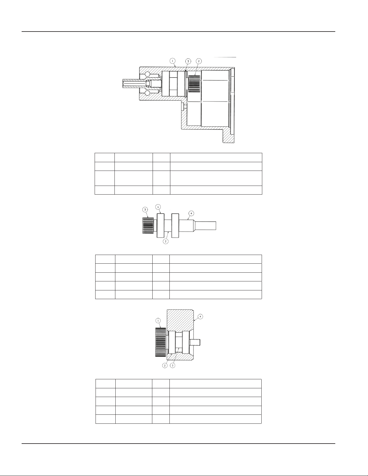
Concrete Vibrator, Backpack Model WBP50
W402600 Speed Increaser Assembly, 2 of 4
Item Part Number Qty Description
1 W402601 1 Housing, speed increaser, machined
2 W402620 1
3 W402125 1 Ring, retaining; internal
Gear assembly, output, speed
increaser
Item Part Number Qty Description
1 W419661 2 Bearing, ball, deep groove
2 W402131 1 Spacer, bearing
3 W402619 1 Gear, output shaft, machined
4 W402189 1 Driver, hex; backpack; black oxide
Item Part Number Qty Description
1 W402614 1 Gear, input shaft, machined
2 W419661 2 Bearing, ball; deep groove
3 W402131 1 Spacer, bearing
4 W402602 1 Bearing adapter, speed increaser
Page 20 March 2014
Page 21
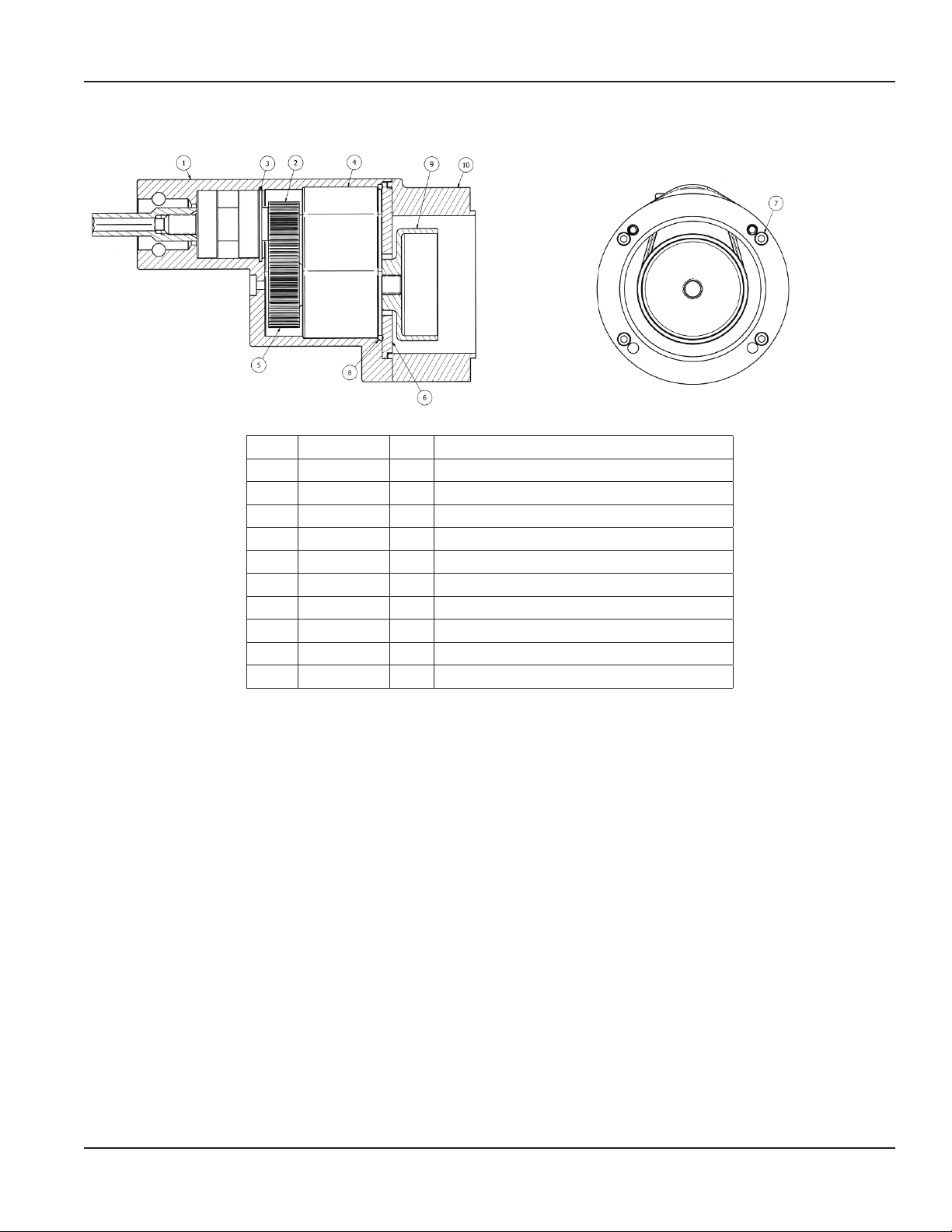
W402600 Speed Increaser Assembly, 3 of 4
Item Part Number Qty Description
1 W402601 1 Housing, speed increaser, machined
2 W402620 1 Gear assembly, output, speed increaser
3 W402125 1 Ring, retaining, internal
4 W402602 1 Bearing, adapter, speed increaser
5 W402615 1 Gear assembly, input, speed increaser
6 W402610 1 Plate; bearing adapter retainer
7 W402628 4 Screw, socket head cap; #10-24 x 2-1/4" long; Z.P.
8 W402627 1 O-ring, seal, speed increaser
9 W402187 1 Drum, clutch; backpack; Honda; Noram
10 W402612 1 Bracket; motor mounts; speed increaser
User Manual
Page 21 March 2014
Page 22
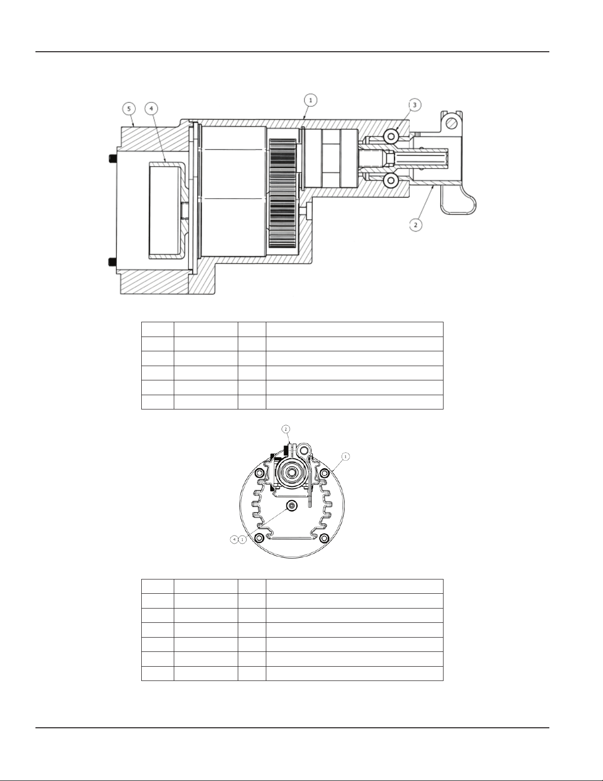
Concrete Vibrator, Backpack Model WBP50
W402600 Speed Increaser Assembly, 4 of 4
Item Part Number Qty Description
1 W402601 1 Housing, speed increaser; machined
2 W402607 1 Coupling; quick disconnect; backpack
3 W402625 2 Shoulder screw; hex head self-locking; 1/4"-20
4 W402187 1 Drum, clutch; backpack; Honda; Noram
5 W402612 1 Bracket; motor mounts; speed increaser
Item Part Number Qty Description
1 W402601 1 Housing, speed increaser; machined
2 W402607 1 Coupling; quick disconnect; backpack
3 W402152 2 Screw, button head cap; 1/4"--28 x 0.25
4 W402153 1 Washer, nylon
4 W402187 1 Drum, clutch; backpack; Honda; Noram
5 W402612 1 Bracket; motor mounts; speed increaser
Page 22 March 2014
Page 23
W402316 Replacement Clutch Kit
Item Part Number Qty Description
— 402316 1
Clutch assembly, 0.625 diameter straight shaft with 3/16" keyway for Honda engine hub bore diameter
0.6250 +0.0000/–0.0020
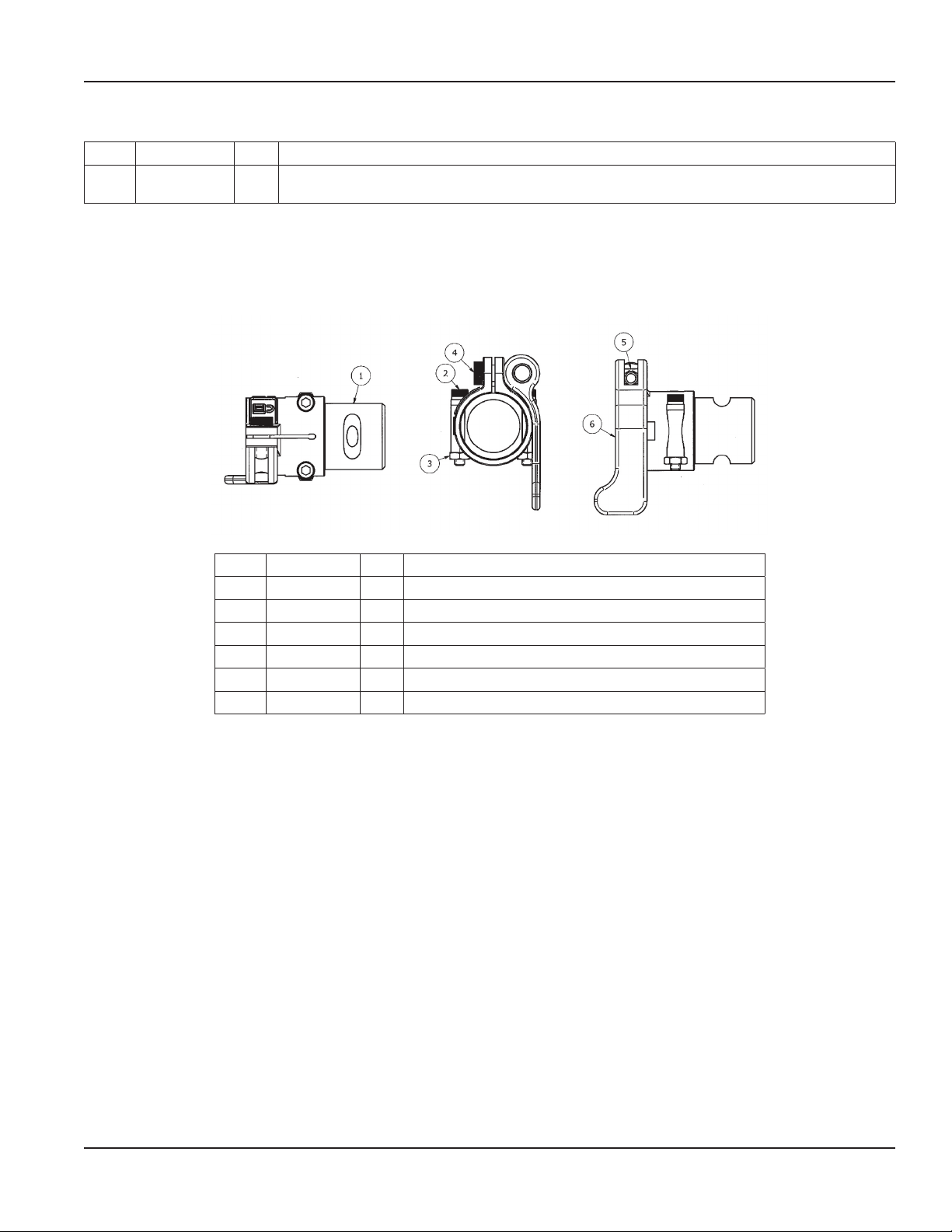
W402630 Quick Disconnect Adapter
User Manual
Item Part Number Qty Description
1 402607 1 Quick disconnect connector; speed increaser; Honda
2 423337 2 Quick disconnect screw
3 423336 2 Nut, hex, #10-24
4 423332 1 Quick disconnect self-locking shoulder screw
5 423331 1 Quick disconnect lever bushing
6 423330 1 Quick disconnect lever
Page 23 March 2014
Page 24

Trademarks appearing in this document are the property of their respective entities.
Due to continuous research, product improvements and enhancements, Badger Meter reserves the right to change product or system specications without notice, except to the
extent an outstanding contractual obligation exists. © 2014 Badger Meter, Inc. All rights reserved.
[email protected] | www.wycotool.com
Phone: 262-639-6770 | Fax: 262-639-2023
Wyco Tool | 8635 Washington Avenue | Racine, WI 53406-3738 USA Legacy Document Number: 01-VBR-UM-00372
 Loading...