

Page 1
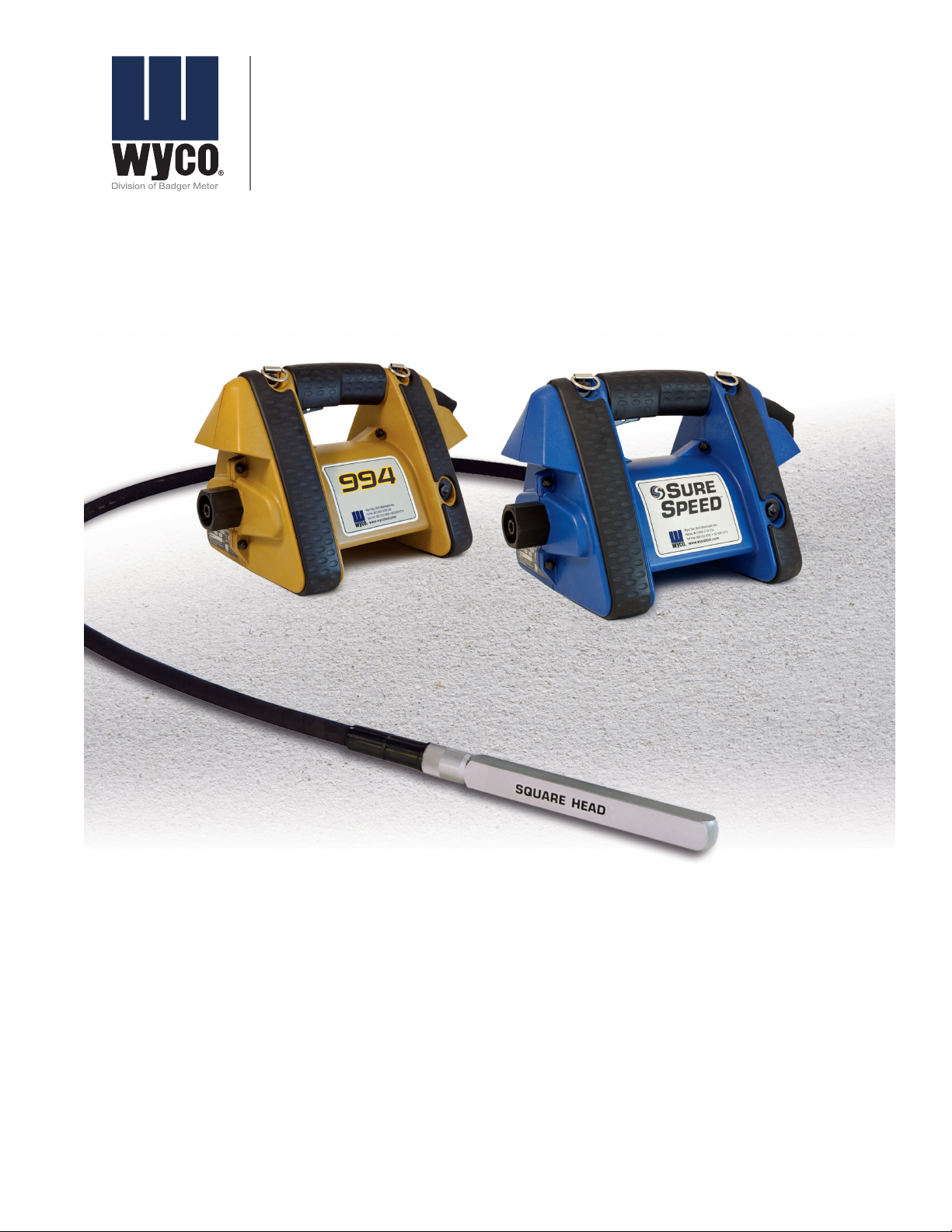
Flex Shaft Concrete Vibrators
SureSpeed and 994
VBR-UM-00043-EN-03 (June 2014)
User Manual
Page 2

Flex Shaft Concrete Vibrator
Page ii June 2014
Page 3

User Manual
CONTENTS
General Power Tool Safety Warnings . . . . . . . . . . . . . . . . . . . . . . . . . . . . . . . . . . . . . . . . . . . . . . . . . . . . . . . . . 5
Work Area Safety . . . . . . . . . . . . . . . . . . . . . . . . . . . . . . . . . . . . . . . . . . . . . . . . . . . . . . . . . . . . . . . . . . . 5
Electrical Safety. . . . . . . . . . . . . . . . . . . . . . . . . . . . . . . . . . . . . . . . . . . . . . . . . . . . . . . . . . . . . . . . . . . . 5
Personal Safety . . . . . . . . . . . . . . . . . . . . . . . . . . . . . . . . . . . . . . . . . . . . . . . . . . . . . . . . . . . . . . . . . . . . 5
Power Tool Use and Care . . . . . . . . . . . . . . . . . . . . . . . . . . . . . . . . . . . . . . . . . . . . . . . . . . . . . . . . . . . . . . 5
Service . . . . . . . . . . . . . . . . . . . . . . . . . . . . . . . . . . . . . . . . . . . . . . . . . . . . . . . . . . . . . . . . . . . . . . . . . 5
Emissions. . . . . . . . . . . . . . . . . . . . . . . . . . . . . . . . . . . . . . . . . . . . . . . . . . . . . . . . . . . . . . . . . . . . . . . . 6
Safety Symbol Explanations. . . . . . . . . . . . . . . . . . . . . . . . . . . . . . . . . . . . . . . . . . . . . . . . . . . . . . . . . . . . . . . 6
Additional Safety Note . . . . . . . . . . . . . . . . . . . . . . . . . . . . . . . . . . . . . . . . . . . . . . . . . . . . . . . . . . . . . . . 6
Introduction. . . . . . . . . . . . . . . . . . . . . . . . . . . . . . . . . . . . . . . . . . . . . . . . . . . . . . . . . . . . . . . . . . . . . . . . . 6
Operation . . . . . . . . . . . . . . . . . . . . . . . . . . . . . . . . . . . . . . . . . . . . . . . . . . . . . . . . . . . . . . . . . . . . . . . . . . 7
Before Starting the Motor . . . . . . . . . . . . . . . . . . . . . . . . . . . . . . . . . . . . . . . . . . . . . . . . . . . . . . . . . . . . . 7
Setup . . . . . . . . . . . . . . . . . . . . . . . . . . . . . . . . . . . . . . . . . . . . . . . . . . . . . . . . . . . . . . . . . . . . . . . . . . . . . 8
Connecting the Vibrating Casing
(Quick-Disconnect Connections) . . . . . . . . . . . . . . . . . . . . . . . . . . . . . . . . . . . . . . . . . . . . . . . . . . . . . . . . . 8
Disconnecting the Vibrator Casing
(Quick-Disconnect) . . . . . . . . . . . . . . . . . . . . . . . . . . . . . . . . . . . . . . . . . . . . . . . . . . . . . . . . . . . . . . . . . 9
Connecting the Vibrating Casing
(Threaded Connections) . . . . . . . . . . . . . . . . . . . . . . . . . . . . . . . . . . . . . . . . . . . . . . . . . . . . . . . . . . . . . . 9
Disconnecting the Vibrator Casing
(Threaded Connector) . . . . . . . . . . . . . . . . . . . . . . . . . . . . . . . . . . . . . . . . . . . . . . . . . . . . . . . . . . . . . . 10
Parts. . . . . . . . . . . . . . . . . . . . . . . . . . . . . . . . . . . . . . . . . . . . . . . . . . . . . . . . . . . . . . . . . . . . . . . . . . . . . 12
Preventive Maintenance . . . . . . . . . . . . . . . . . . . . . . . . . . . . . . . . . . . . . . . . . . . . . . . . . . . . . . . . . . . . . . . . 12
Brush Removal . . . . . . . . . . . . . . . . . . . . . . . . . . . . . . . . . . . . . . . . . . . . . . . . . . . . . . . . . . . . . . . . . . . 13
Brush Replacement . . . . . . . . . . . . . . . . . . . . . . . . . . . . . . . . . . . . . . . . . . . . . . . . . . . . . . . . . . . . . . . . 13
Filter Replacement. . . . . . . . . . . . . . . . . . . . . . . . . . . . . . . . . . . . . . . . . . . . . . . . . . . . . . . . . . . . . . . . . 13
Electric Vibrator Head
Service & Maintenance . . . . . . . . . . . . . . . . . . . . . . . . . . . . . . . . . . . . . . . . . . . . . . . . . . . . . . . . . . . . . . . . . 13
Flexible Shaft Lubrication Procedure . . . . . . . . . . . . . . . . . . . . . . . . . . . . . . . . . . . . . . . . . . . . . . . . . . . . . 14
Extension Cords . . . . . . . . . . . . . . . . . . . . . . . . . . . . . . . . . . . . . . . . . . . . . . . . . . . . . . . . . . . . . . . . . . 15
Electric Vibrator Head Assembly Drawings & Parts Lists . . . . . . . . . . . . . . . . . . . . . . . . . . . . . . . . . . . . . . . . . . . . 15
Vibrator Head Model 750-D . . . . . . . . . . . . . . . . . . . . . . . . . . . . . . . . . . . . . . . . . . . . . . . . . . . . . . . . . . . 16
Vibrator Head Model 750-EH . . . . . . . . . . . . . . . . . . . . . . . . . . . . . . . . . . . . . . . . . . . . . . . . . . . . . . . . . . 16
Vibrator Head Models 750-FI, 750-GI, 750-LI and 750-MI . . . . . . . . . . . . . . . . . . . . . . . . . . . . . . . . . . . . . . . . . 17
Vibrator Head Model 750-SBI . . . . . . . . . . . . . . . . . . . . . . . . . . . . . . . . . . . . . . . . . . . . . . . . . . . . . . . . . . 17
Restrictions of Hazardous Substances (Rohs) Directive. . . . . . . . . . . . . . . . . . . . . . . . . . . . . . . . . . . . . . . . . . . . . 18
Waste Electrical and Electronic Equipment (WEEE) Directive . . . . . . . . . . . . . . . . . . . . . . . . . . . . . . . . . . . . . . . . . 18
Page iii June 2014
Page 4

Flex Shaft Concrete Vibrator
Model Number
Serial Number
Date Purchased
Page iv June 2014
Page 5

WARNING
READ ALL SAFETY WARNINGS AND ALL INSTRUCTIONS.
FAILURE TO FOLLOW THE WARNINGS AND INSTRUCTIONS
MAY RESULT IN ELECTRIC SHOCK, FIRE AND/OR SERIOUS
INJURY.
GENERAL POWER TOOL SAFETY WARNINGS
OTE:N Save all warnings and instructions for
future reference.
OTE:N The term power tool in the warnings refers to your
mains-operated (corded) power tool or batteryoperated (cordless) power tool.
Work Area Safety
1. Keep work area clean and well lit.
2. Do not operate power tools in explosive atmospheres,
such as in the presence of ammable liquids, gases or
dust. Power tools create sparks which may ignite the dust
or fumes.
3. Keep children and bystanders away while operating a
power tool.
User Manual
Personal Safety
1. Do not use a power tool while you are tired or under the
inuence of drugs, alcohol or medication to avoid risk of
serious personal injury.
2. Always wear eye protection. Other protective equipment
such as dust mask, non-skid safety shoes, hard hat,
or hearing protection should be used in appropriate
conditions to reduce personal injuries.
3. Ensure the switch is in the OFF position before
connecting to power source and/or battery pack, picking
up or carrying the tool.
4. Remove any adjusting key or wrench before turning
the power tool on. A wrench or a key left attached
to a rotating part of the power tool may result in
personal injury.
5. Do not overreach. Keep proper footing and balance
at all times.
6. Do not wear loose clothing or jewelry. Keep your
hair, clothing and gloves away from moving parts.
Loose clothes, jewelry or long hair can be caught in
moving parts.
7. If devices are provided for the connection of dust
extraction and collection facilities, ensure these are
connected and properly used. Use of dust collection can
reduce dust-related hazards.
Power Tool Use and Care
Electrical Safety
1. Power tool plugs must match the outlet. Never modify
the plug in any way. Do not use any adapter plugs with
earthed or grounded power tools. Unmodied plugs and
matching outlets will reduce risk of electric shock.
2. Avoid body contact with earthed or grounded surfaces
such as pipes, radiators, ranges, and refrigerators. There is
an increased risk of electric shock if your body is earthed
or grounded.
3. Do not expose power tools to rain or wet conditions.
Water entering a power tool will increase the risk of
electric shock.
4. Do not abuse the cord. Never use the cord for carrying,
pulling or unplugging the power tool. Keep cord away
from heat, oil, sharp edges or moving parts. Damaged or
entangled cords increase the risk of electric shock.
5. When operating a power tool outdoors, use an extension
cord suitable for outdoor use to reduce the risk of
electric shock.
6. If operating a power tool in a damp location is
unavoidable, use a residual current device (RCD)
protected supply to reduce the risk of electric shock.
OTE:N The term residual current device (RCD) may be
replaced by the term ground fault circuit interrupter
(GFCI) or earth leakage circuit breaker (ELCB).
1. Do not force the power tool. Use the correct power tool
for your application.
2. Do not use the power tool if the switch does not turn it
on and o. Any power tool that cannot be controlled with
the switch is dangerous and must be repaired.
3. Disconnect the plug from the power source and/or the
battery pack from the power tool before making any
adjustments, changing accessories, or storing power tools
to reduce the risk of starting the power tool accidentally.
4. Store idle power tools out of the reach of children and do
not allow persons unfamiliar with the power tool or these
instructions to operate the power tool.
5. Maintain power tools. Check for misalignment or binding
of moving parts, breakage of parts and any other
condition that may aect operation. If damaged, have the
power tool repaired before use.
6. Keep cutting tools sharp and clean.
7. Use the power tool, accessories, tool bits, and like
equipment in accordance with these instructions, taking
into account the working conditions and the work
to be performed.
Service
Have your power tool serviced by a qualified repair person
using only identical replacement parts to ensure the tool is
safe to use.
Page 5 June 2014
Page 6
Flex Shaft Concrete Vibrator
Emissions
1. Declared noise emission values:
K = 0.69 dB
LpA = 83.1 dB
LWA = 94.1 dB
OTE:N Wear hearing protection.
2. Declared vibrator emissions:
Front Handle = 4.28 m/s
K = 1.50 m/s
2
Rear Handle = 2.41 m/s
K = 1.50 m/s
2
2
2
OTE:N The declared vibration total value has been
measured in accordance with a standard test
method and may be used for comparing one tool
with another. The declared vibration total value may
also be used in a primary assessment of exposure.
WARNING
THE VIBRATION EMISSION DURING ACTUAL USE OF THE
POWER TOOL CAN DIFFER FROM THE DECLARED TOTAL
VALUE DEPENDING ON THE WAYS IN WHICH THE TOOL IS
USED.
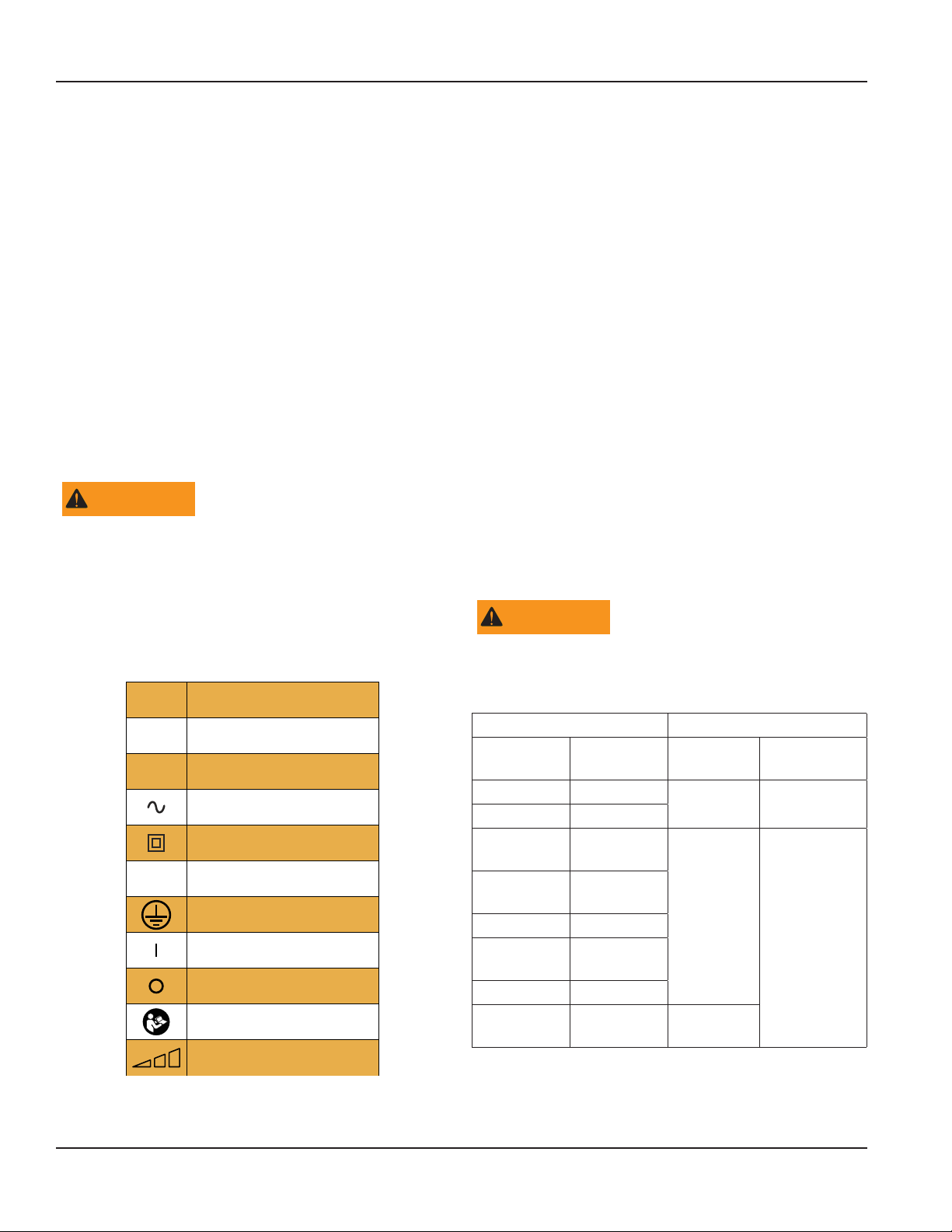
SAFETY SYMBOL EXPLANATIONS
Volts
V
Amperes
A
Hertz
Hz
Alternating Current
Class II Tool
IPX4
IP Symbol
Ground Terminal (Protective Earthing)
ON
OFF
Refer to Instruction Manual
Variability in Steps
Additional Safety Note
Double insulated tools are equipped with a polarized plug
(one blade is wider than the other). This plug will fit in a
polarized outlet only one way. If the plug does not fit fully
in the outlet, reverse the plug. If it still does not fit, contact
a qualified electrician to install a polarized outlet. Do not
change the plug in any way. Double insulation eliminates the
need for the three-wire grounded power cord and grounded
power supply system.
INTRODUCTION
This concrete vibrator motor is used to power concrete flex
shaft vibrators which provide vibration to consolidate freshly
poured concrete. The vibration is created by an eccentric (off
center) weight within the vibrator head. As the weight spins
it forces the head housing to move within the fresh concrete.
The continuous head movement agitates the concrete
mixture resulting in significantly reduced voids.
This motor can be used with any valid Wyco vibrator
head and shaft combination. See Table 1: Head and shaft
combinations on page 6 or common combinations. Shafts
are available in lengths of 2, 5, 7, 10, 14, 20 and 30 feet (0.61,
1.52, 2.13, 3.05, 4.27, 6.1, and 9.14 m).
WARNING
DO NOT USE NON-APPROVED PARTS. THE USE OF NONAPPROVED PARTS MAY CAUSE A HAZARDOUS CONDITION
FOR THE OPERATOR.
Vibrator Head Vibrator Shaft
Size in.
(mm)
13/16 (4.76) 750-D
1 (25.4) 750-EH
1-3/8
(34.92)
1-3/4
(44.45)
2 (50.8) 750-LI
2-1/4
(57.15)
2-1/2 (63.5) 750-SBI
1-3/8
(34.92)
Model No Length CK Series
2...20 ft
(0.61...6.1m)
8900
750-FI
750-GI
2...20 ft
(0.61...6.1m)
9500
750-MI
750-FI
Table 1: Head and shaft combinations
30 ft
(9.14 m)
Figure 1: Safety symbols
Page 6 June 2014
Page 7
User Manual
OPERATION
Before Starting the Motor
DANGER
DO NOT USE DAMAGED EQUIPMENT. INSPECT THE
VIBRATOR FOR DAMAGE PRIOR TO USING THIS
EQUIPMENT. READ, UNDERSTAND AND FOLLOW ALL
SAFETY AND MAINTENANCE INSTRUCTIONS IN THIS
MANUAL. CAREFULLY CHECK THAT THE POWER CORD
HAS NO CUTS OR EXPOSED WIRES. VERIFY MOTOR
HOUSING IS INTACT. CHECK ALL ACORN NUTS TO VERIFY
THEY ARE TIGHTENED.
DANGER
DO NOT START THE MOTOR WITHOUT A SHAFT
CONNECTED. THE EXPOSED SHAFT CONNECTION
PRESENTS A SAFETY HAZARD AS IT ROTATES AT HIGH
SPEED. CLOTHING OR SKIN MAY BECOME ENTANGLED IN
THE SHAFT CONNECTION CAUSING INJURY.
Ensure that the motor, shaft and head are connected
securely. See Preventive Maintenance on page 12.
Ensure that the power plug is connected to the appropriate
power source.
Ensure that the motor is not immersed in concrete and that
any cord connections are not in water or fresh concrete.
Turn vibrator on by moving the rocker switch to I. See
Table 3: Concrete vibrator replacement parts on page 12 for
switch location.
OTE:N The Sure Speed has been designed with a soft
start and will slowly ramp up to speed over a 1
second period.
Insert the vibrator head into the concrete to be consolidated.
Do not run the vibrator head outside of fresh concrete for an
extended period of time. The vibrator depends on moving
concrete to cool the bearings.
Avoid sharp bends in the flex shaft during operation. Sharp
bends reduce shaft life.
Remove the vibrator head from concrete and turn the rocker
switch to O. See Table 3: Concrete vibrator replacement parts
on page 12 for switch location.
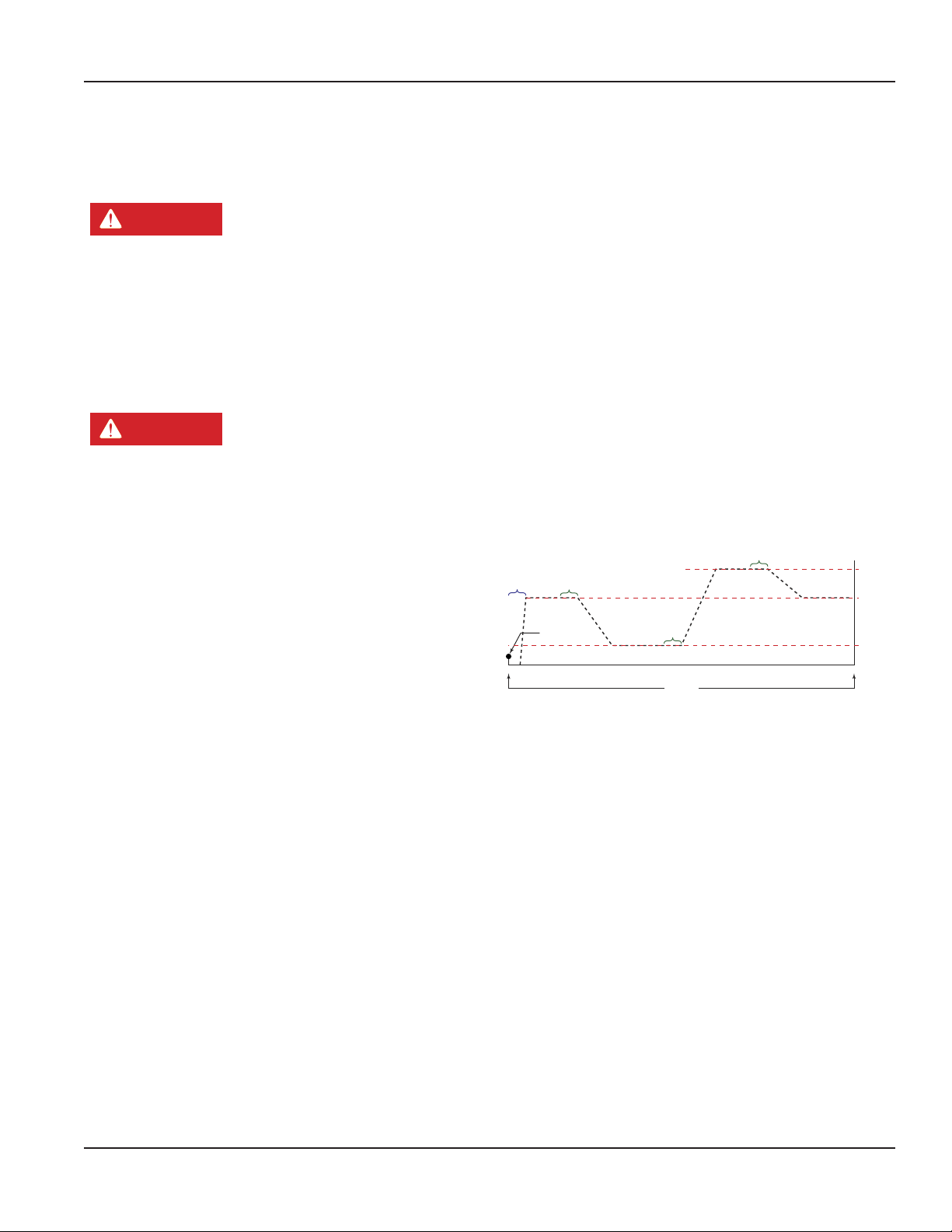
Variable Speed Control Models Only
The variable speed option allows the operator to choose
between 8000, 10,500, and 12,000 VPM (vibrations
per minute).
OTE:N This instruction only pertains to model numbers that
start with WV.
OTE:N See “Concrete vibrator replacement parts” on page
12 for switch and button locations.
When the power switch is turned on, the motor will always
start at 10,500 VPM. From the time the power is applied
there is a 20 second window in which to choose one of the
alternate motor speeds.
Hold the speed control button for one second to change the
motor speed to 8000 VPM. Release the speed control button
and then press it again for one second to increase the motor
speed to 12,000 VPM.
Release and then press the speed control button a third time
for one second to return the motor to 10,500 VPM. To reset
the 20 second speed change period, turn the power switch
off and then on again.
Speed Control
Button Held for
At Least 1 sec
12,000
10,500
VPM
8000
7000
1 sec
Ramp-up
Speed Control
Button Held for
At Least 1 sec
Power Switch
Turned ON
Speed Control
Button Held for
At Least 1 sec
20 sec
Figure 2: Variable speed control timing
Page 7 June 2014
Page 8
Flex Shaft Concrete Vibrator
SETUP
The motor has several options for connecting the core and
casing assembly to the motor housing. For all available
connections, see Figure 13 “Core and casing configurations” on
page 11.
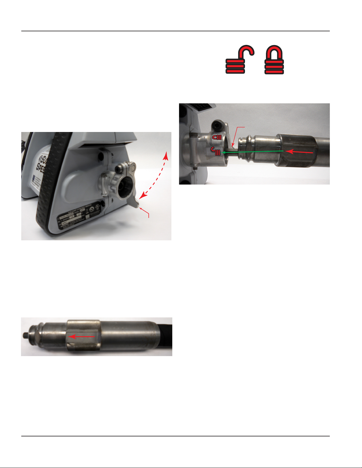
Connecting the Vibrating Casing (Quick-Disconnect Connections)
OTE:N The casing must be fitted with a
quick-disconnect end.
Locking Lever
Figure 3: Quick-disconnect fitting
1. Be sure the locking lever on the quick-disconnect
connector on the motor is in the up position. See Figure 3.
2. Locate the core and casing. Identify the side of the
casing that has the connection arrow and position the
casing with the arrow face to the left as viewed from
the vibrator head end. See Figure 4. This side should face
to the left when the casing is held directly behind the
quick-disconnect.
UnLocked
Figure 5: Unlock/Lock icons
Locked
Shaft
Figure 6: Core/Casing alignment
5. Insert the casing and line up the shaft and driver so the
shaft slides into the driver.
6. Rotate the casing until the arrow lines up with the lock
icon on the quick-disconnect connector.
7. Push down on the locking lever to clamp the
casing into the quick-disconnect connector. The
locking lever should bottom out on the side of the
quick-disconnect connector.
OTE:N If the casing feels loose or too tight after pushing
down on the locking lever, raise the lever until the
lever is horizontal then rotate the hex head screw
with a #4 Allen wrench in either direction to tighten
or loosen. Be careful to not loosen the lever too
far or the lever bushing and screw will unthread
and could fall apart. After the adjustments are
completed, push lever back down to bottom out to
connector. This procedure may need to be repeated
to get desired tight or lose condition. See Figure 7.
Figure 4: Casing arrow location
3. Align the end of the core with the driver inside the
quick-disconnect tting on the motor.
4. Align the arrows on the casing end with the unlock icon
on the quick-disconnect connector. The unlock and lock
positions are shown by the unlock and lock icons (see
Figure 5) on the side of the quick-disconnect tting.
See Figure 6.
Page 8 June 2014
Page 9
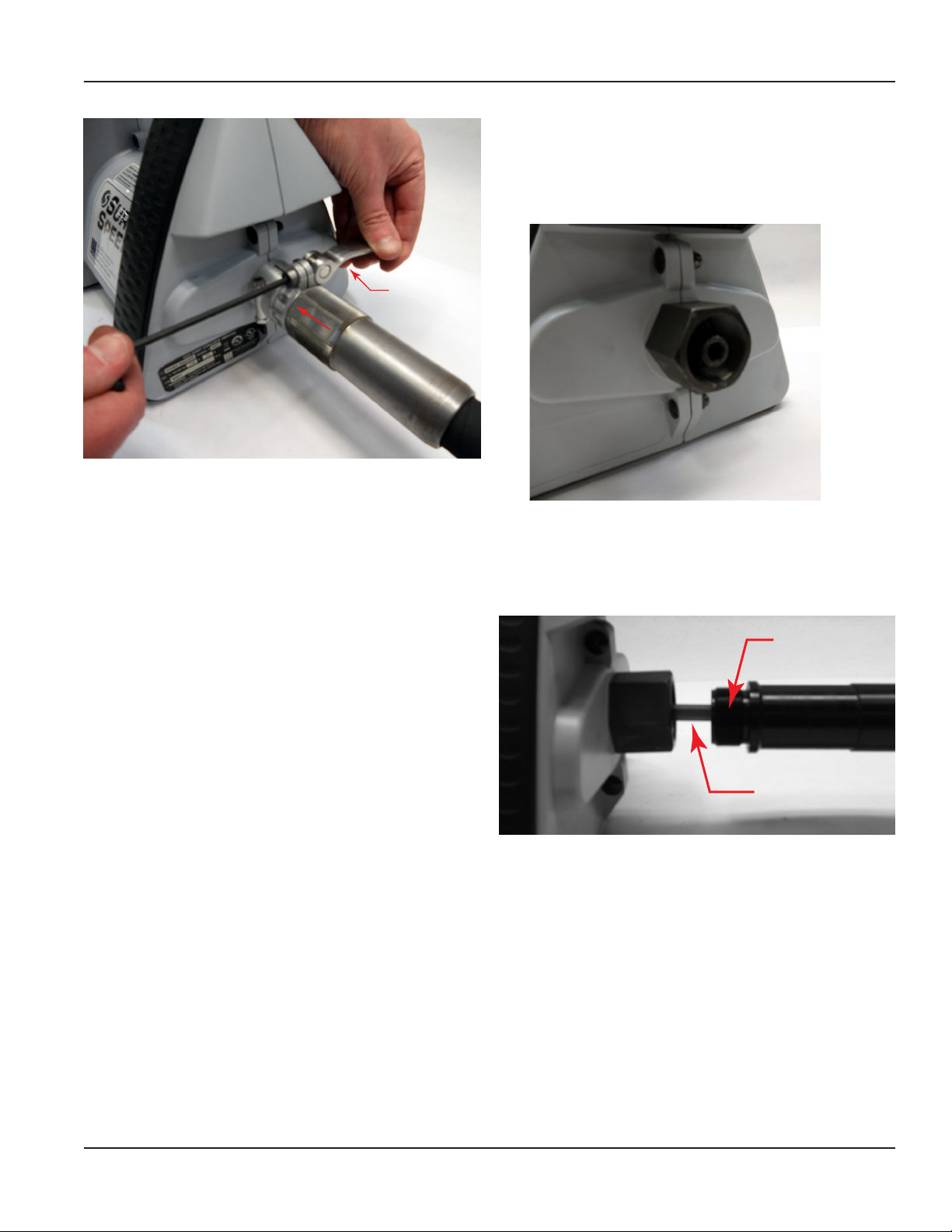
Figure 7: Locking lever adjustment
User Manual
Connecting the Vibrating Casing (Threaded Connections)
OTE:N The casing must be fitted with a thread
connector end.
Locking
Lever
Disconnecting the Vibrator Casing (Quick-Disconnect)
1. Be sure the quick-disconnect locking lever on the motor
is in the up position.
2. Rotate the core and casing counterclockwise from the
lock position to the unlock position.
3. Pull the casing end straight out of the quick-disconnect
connector on the motor.
4. Be sure that the locking lever is in the down position
when storing the motor to avoid damage to the lever.
Figure 8: Threaded casing connector
1. Line up threads of the shaft with the threaded motor
connector. Hold the casing end rmly and rotate the
casing until it engages into the motor.
Threads
Shaft
Figure 9: Shaft insertion
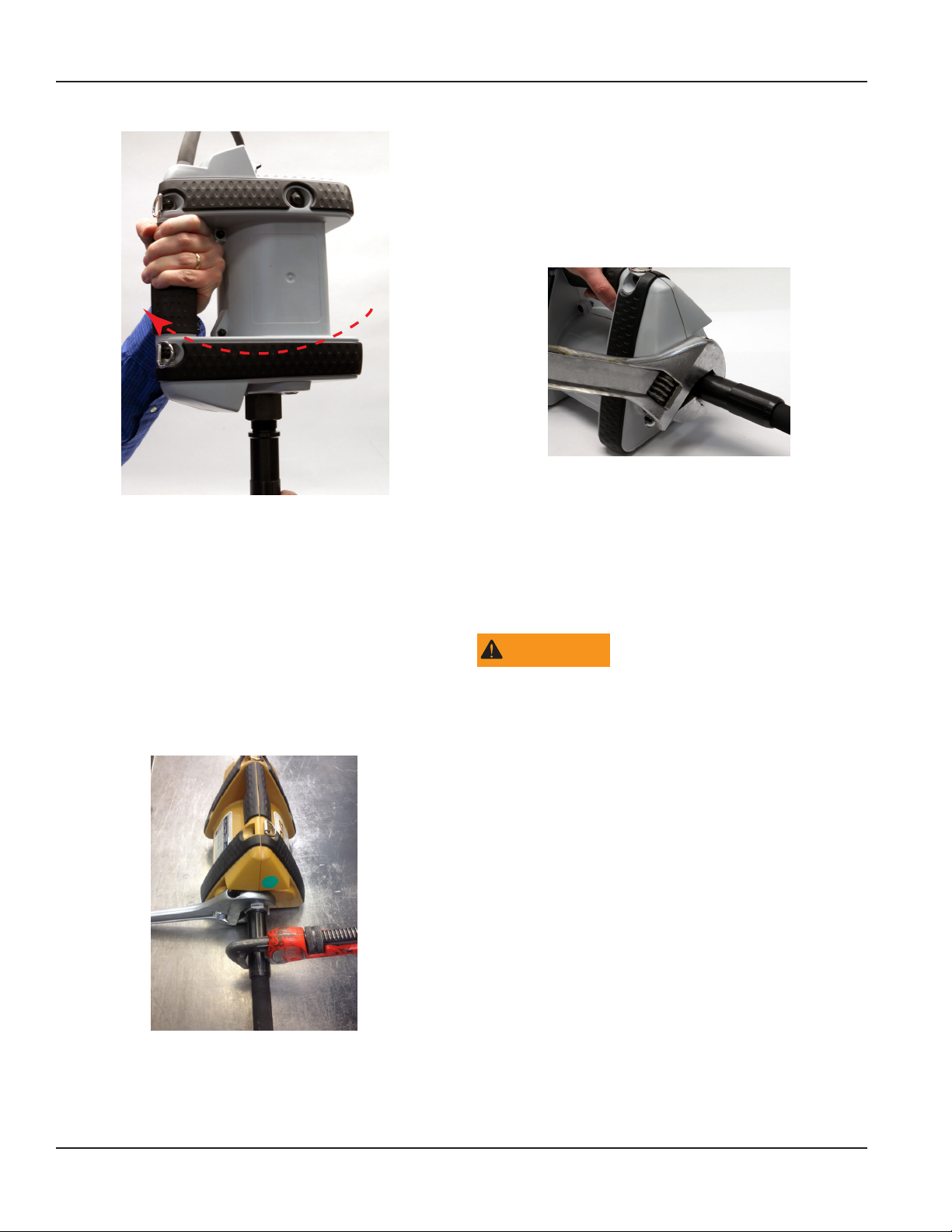
2. Hold the casing assembly in one hand while carefully
rotating the motor counterclockwise until motor is snug
to the shaft. See Figure 10.
Page 9 June 2014
Page 10
Flex Shaft Concrete Vibrator
Disconnecting the Vibrator Casing (Threaded Connector)
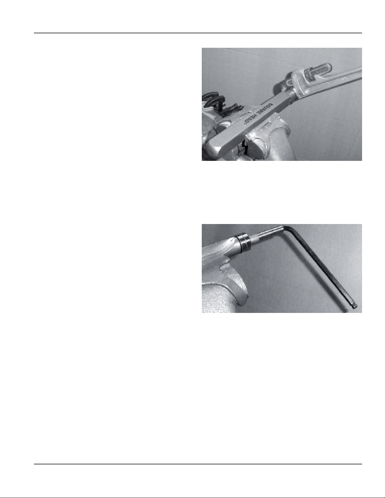
1. Carefully loosen the hex motor connector, using a
crescent wrench on the motor and a pipe wrench on
the ex shaft assembly, until the motor assembly can be
rotated by hand in a counterclockwise direction.
See Figure 11.
R
o
t
a
Figure 10: Motor rotation
OTE:N The motor may be taken off of the work surface
allowing the motor housing to spin in the air while
holding onto the flex shaft with a hand or with vise.
Do not over tighten or reef as this may damage the
plastic motor housing.
4. Once threads are started, rotate motor assembly until the
motor assembly stops turning. See Figure 10.
5. Use a crescent wrench to hold the hex motor connector
and a pipe wrench on the ex shaft to tighten.
See Figure 11.
n
o
i
t
Figure 12: Hex motor connection
2. Carefully rotate the motor until it and the casing separate
from one another. Do not pull the core end too far out
of the casing end or the head will have to be removed to
realign the core with the head driver.
3. Place casing end of shaft into a vice and place an
adjustable wrench to the hex motor connector to tighten
the motor to shaft.
WARNING
TIGHTENING OR TORQUING USING THE MOTOR HANDLE
CAN CAUSE DAMAGE TO MOTOR CASING.
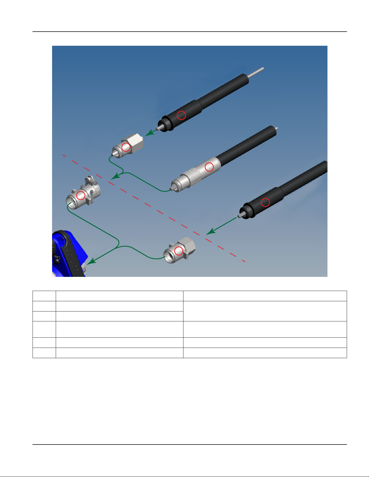
The motor can accommodate any of the 750 series cores
and casings.
The motor is ordered as either a dedicated quick-disconnect
connection or a dedicated threaded connection version.
If the threaded version was ordered it cannot be used with
the quick-disconnect core and casing. If the quick-disconnect
version was ordered threaded core and casings can be used
with the addition of a thread to quick-disconnect adapter.
The configuration options are shown in Figure 13.
Figure 11: Crescent wrench and pipe wrench placement
6. The vibrator assembly is now ready to use.
Page 10 June 2014
Page 11
User Manual
5
3
4
1
5
2
Figure 13: Core and casing configurations
Item Description Notes
1 Quick-Disconnect Motor End
2 Threaded Motor End
3 Threaded to Quick-Disconnect Adapter
4 Quick-Disconnect Core and Casing
5 Threaded Core and Casing
Table 2: Core and casing options
These motor ends are part of the motor assembly. They are not
interchangeable and are part of the specific part number.
Wyco PN W423-500 allows threaded core and casings to be used
with quick-disconnect motor.
Page 11 June 2014
Page 12
Flex Shaft Concrete Vibrator
PARTS
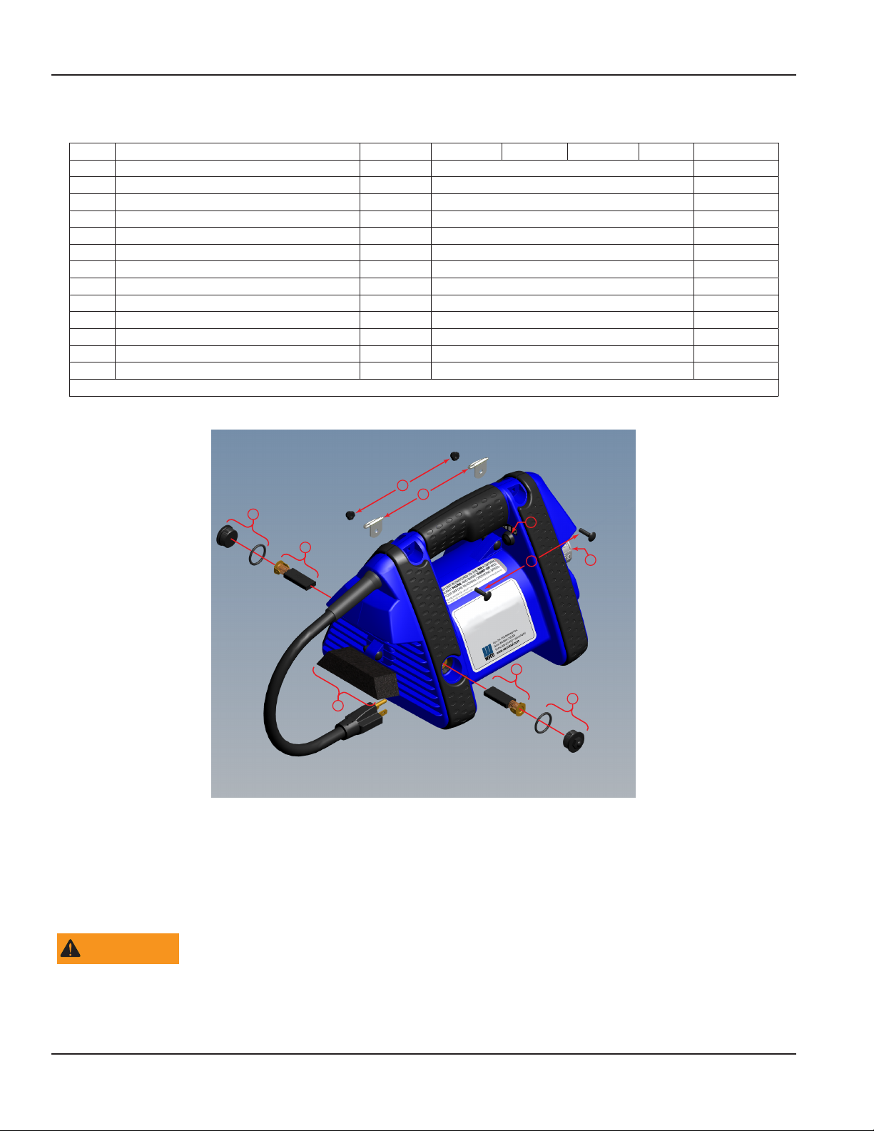
Item Description Quantity WVD1 WVG1 WSD1 WSG1 WSG2
1 D-Ring 2 W819014 W819014
2 Filter, Intake 1 W423132 W423132
3 Carriage Screw; 10-32, 3/4 in (19.05 mm) 9 W423140 W423140
4 Acorn Nut, Self-locking; 10-32 UNF 9 W423141 W423141
5 Assembly, Brush & Spring; 115 V AC 2 W423117
5 Assembly, Brush & Spring; 230 V AC 2 W423118
6 Brush Cap with O-Ring 2 W423114 W423114
7 Casing Connector
8 Variable Speed Switch
514-O Non-foaming Vibrator Oil 14 oz W655-143 W655-143
Strap, Carry (not shown) 1 W819013 W819013
514-B Shaft Lubricant 14 oz W655-140 W655-140
Permatex 11 oz W657055 W657055
See Figure 14 for parts locations
Table 3: Concrete vibrator replacement parts
4
1
6
5
2
Figure 14: Parts locations
8
3
5
7
6
PREVENTIVE MAINTENANCE
Wyco vibrator motors are designed to operate 50…100 hours between normal preventive maintenance intervals. The service
instructions below should be followed to perform the preventive maintenance.
WARNING
THERE ARE NO USER SERVICEABLE PARTS CONTAINED WITHIN THE MOTOR HOUSING. OPENING THE MOTOR HOUSING
MAY BE DANGEROUS AND WILL VOID THE WARRANTY. ANY REPAIRS THAT REQUIRE OPENING THE MOTOR HOUSING
SHOULD BE PERFORMED AT AN AUTHORIZED WYCO SERVICE CENTER OR AT THE WYCO FACTORY. USE ONLY FACTORY
AUTHORIZED REPLACEMENTS PARTS.
Page 12 June 2014
Page 13
Brush Removal
For the location of the parts used in the following procedures
see Figure 14 and Table 3.
1. Disconnect the line cord from the power source.
2. Lay the motor on its side with the brush cap (6) facing up.
3. Use a 1/2 in 6-sided socket to unscrew the plastic brush
cap (6) from the motor half.
4. The brush spring (5) will pop out. Carefully remove the
brush spring by gently pulling on the spring.
5. Repeat these steps for the opposite side.
Brush Replacement
OTE:N Brushes should be replaced in pairs.
1. Inspect and replace damaged O-rings.
2. Lubricate the O-ring prior to cap installation
3. Align the new brush (5) with brush holder. Insert the
new brush.
4. Push the spring into the holder as you screw the brush
cap back into the housing.
OTE:N The O-ring must be on the brush cap before you
screw the cap into the housing.
5. Torque the brush cap (6) to 35 in. lb.
6. Repeat these steps for the opposite side.
User Manual
Figure 15: End cap removal
2. Pull the eccentric rotor assembly out of the housing. If the
bearings are stuck and you have diculty removing them
from the housing, screw the end cap partly back into the
housing and bounce the head and cap down on a block
of wood in order to loosen the bearings from their seat,
then pull out the rotor assembly. See Figure 16.
Filter Replacement
1. Pull the old lter down from the housing with
your ngers.
2. Place the new lter (2) in the housing, tapered side up.
See Figure 14.
ELECTRIC VIBRATOR HEAD SERVICE & MAINTENANCE
MPORTANTI
Service the vibrator head after every 50 hours of operation for
trouble-free running on the job.
When servicing, always replace the hex driver, the seals and
the bearings, or bushing for 750-D & 750-EH heads.
See Electric Vibrator Head Assembly Drawings & Parts Lists on
page 15.
All heads are equipped with seals at the flexible shaft end
and contain oil. The seals serve a double purpose; to keep the
oil in the head and to keep the grease from the flexible shaft
out of the head.
1. Hold the nose end in a vise and unscrew the end cap
counterclockwise with a chain wrench or a good pipe
wrench. See Figure 15.
Figure 16: Bearing Removal
OTE:N Hexagon driver has left hand threads.
3. Flush the rotor assembly and housing with solvent and
wipe all parts clean. Replace bearings, seals and hex
driver. Maintain concentric alignment of the hex driver
with respect to the rotor shaft. Rell with proper amount
of Wyco No. 514-O non-foaming vibrator oil. See Table
4. Apply Loctite 545 adhesive/sealant or equivalent to
threads on both ends of rotor.
Page 13 June 2014
Page 14

Flex Shaft Concrete Vibrator
Head Model Head Size in (mm) Oil Required
750-D 13/16 (20.64) Square 1/2 oz (14 g)
750-EH 1 (25.4) Square 3/4 oz (21 g)
750-FI 1-3/8 (34.93) Square 1 oz (28 g)
750-GI 1-3/4 (44.45) Square 1-1/4 oz (35 g)
750-LI 2 (50.8) Square 2 oz (57 g)
750-MI 2-1/4 (57.15) Square 3-1/2 oz (99 g)
750-SBI 2-1/2 (63.5) Round 1-1/4 oz (35 g)
Table 4: Head oil requirements
4. Replace the rotor assembly into the head housing. Apply
Loctite 545 adhesive/sealant or equivalent all around
the threads of the end cap. Tighten and wipe o excess
Loctite 545 adhesive/sealant.
Flexible Shaft Lubrication Procedure
When vibrators are shipped completely assembled from the
factory, the shafts are lubricated and broken-in. If separate
cores and casings are shipped, they require the following
lubrication and break-in procedure. Core and casing
combinations should be checked for lubricant levels at least
every 50 hours.
To lubricate, lightly coat the core with grease (Wyco 514-B
shaft lubricant) while inserting it into the casing. Do not
over lubricate. Surplus lubricant may get past the seal in
the vibrator head. Over lubrication will also increase the
amount of torque required to operate the vibrator, resulting
in additional stress on the motor and possibly early core and
casing failure.
When adding lubricant on the job, after each 50 hours of
operation, loosen the casing from the motor and pull out the
core about 15…18 inches (318.... 457.2 mm). Apply lubricant
as above to the exposed section of core. Reinstall the core,
making sure that it engages with the vibrator head. During
operation, the grease will travel the full length of the casing.
A break-in procedure is required after the assembly of
separately shipped core and casing. This procedure involves
repeatedly coiling the flex shaft from the head to the motor
while the motor is running. The coiling and uncoiling should
be repeated at least three times for proper break-in.
OTE:N For shorter core and casing combinations, coiling
is not possible. Break-in for short core and casings
requires bending into a U-shape instead of a coil.
Water is one of the greatest enemies of satisfactory
performance of vibrator heads. As the head is submerged in
the mix, water and cement can infiltrate into the head unless
precautions are taken. In addition to securely tightening the
head onto the flexible shaft, the threads on the head and
shaft must be coated with Permatex Form-A-Gasket No.
2. This must be done each and every time that the head is
removed and reinstalled.
Page 14 June 2014
Page 15
User Manual
Extension Cords
When selecting an extension cord for use with Wyco electric motor cord sets using a three-prong polarized plug, an
equivalent plug set must be used for the grounded or earthed version.
MPORTANTI
A grounded or earthed motor requires a grounded or earthed extension cord.
A two-prong extension cord may be used for the double insulated motor. Extension cords must be approved for outdoor use
and the wire gauge of the cord must be appropriate for the expected load. See Table 5.
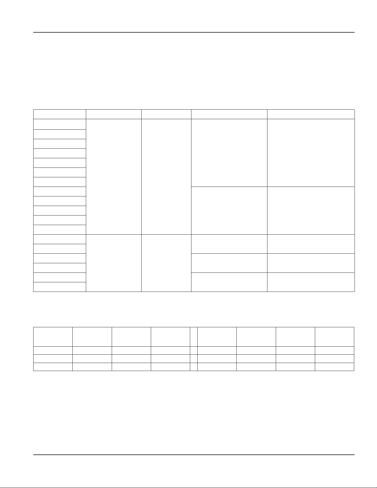
Motor Type Voltage Rated Amps Minimum Wire Size Maximum Cord Length
WSD1
WSD1T
WSG1
WSG1T
W994D1
W994D1T
W994G1
W994G1T
WVD1
WVD1T
WVG1
WVG1T
WSG2
WSG2T
WVG2
WVG2T
W994G2
W994G2T
115 V AC(±15V AC) 15
230 V AC (±30V AC) 7.5
Table 5: Extension cord wire minimum size requirements
14 AWG 100 ft (30.48 m)
12 AWG 150 ft (45.72 m)
16 AWG 100 ft (30.48 m)
14 AWG 150 ft (45.72 m)
16 AWG 100 ft (30.48 m)
ELECTRIC VIBRATOR HEAD ASSEMBLY DRAWINGS & PARTS LISTS
Vibrator
Head Model
750-D D 3/16 (4.76) W877-520 750-GI 1.75B 1-3/4 (44.45) W878-540
750-EH EH 1 (25.4) W877-526 750-LI 2.00B 2 (50.8) W878-563
750-FI 1.38B 1-3/8 (34.92) W878-533 750-MI 2.25B 2-1/4 (57.15) W878-568
OTE:N Vibrator head model 750-SBI is a 2-1/2 in (63.5 mm) round head with no end cap marking.
Assembly PN is # W877-512.
Marking on
End Cap
Square
Size in. (mm)
Assembly
Part No
Table 6: Electric vibrator head models
Vibrator
Head Model
Marking on
End Cap
Square
Size in. (mm)
Assembly
Part No
Page 15 June 2014
Page 16
Flex Shaft Concrete Vibrator
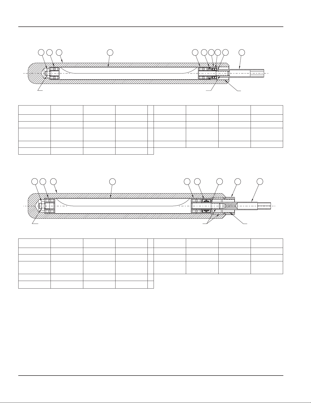
Vibrator Head Model 750-D
1
2
3
LOCTITE 545
4
LOCTITE 545 PERMATEX #2
Figure 17: Model 750-D parts
Item Description Quantity Part No. Item Description
5
2
897
6
Quantity Part No.
1 Nut, Hex Jam 1 W435638 6 Holder, Seal 1
2 Bearing, Ball 4 W097011 7 Seal, Oil 2
3
Housing,
Square
1 W587320 8 Bushing
1
4 Rotor 1 W717340 9 Driver, Hex 1 W382428
5 O-Ring, Buna 1
*
Table 7: Model 750-D parts list
* All of these items available assembled in a kit, PN W747-540.
Vibrator Head Model 750-EH
1
2
3
4
5
2 6 8
7
*
*
*
LOCTITE 545 LOCTITE 545
Figure 18: Model 750-EH parts
PERMATEX #2
Item Description Quantity Part No. Item Description Quantity Part No.
1 Nut, Hex Jam 1 W432710 6 Bushing 1 W177325
2 Bearing, Ball 4 W097012 7 End Cap 1
3
4 Rotor 1 W717345
5 Seal, Oil 2
Housing,
Square
1 W587325 8 Driver, Hex 1 W384447
End cap assembly with seals is PN W207-248.
**
**
Table 8: Model 750-EH parts list
(Order bushing separately.)
**
Page 16 June 2014
Page 17
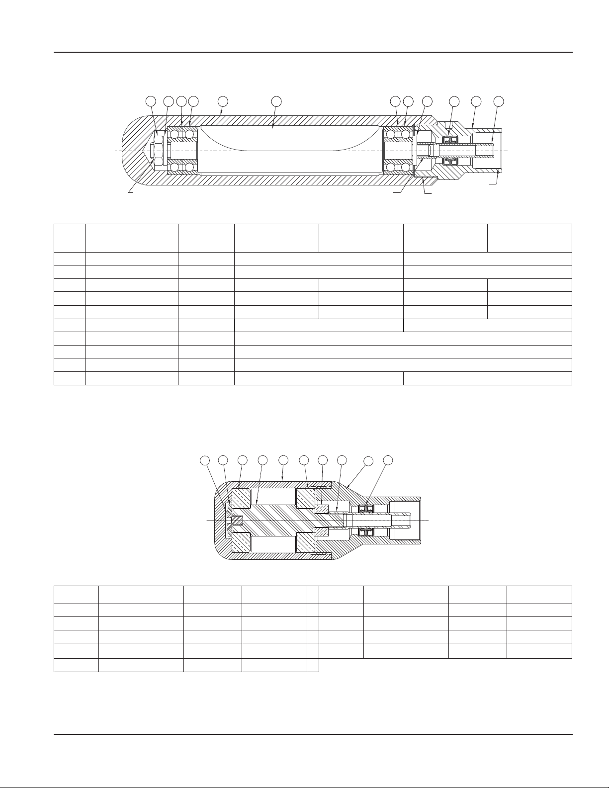
Vibrator Head Models 750-FI, 750-GI, 750-LI and 750-MI
User Manual
1
LOCTITE 545
Item Description Quantity
310 10
2
4
5
Figure 19: Model 750-FI, GI, LI and MI parts
Part No. for
750-FI (1.38B)
Part No. for
750-GI (1.75B)
LOCTITE 545
3 6
PERMATEX #2
LOCTITE 545
Part No. for
750-LI (2.00B)
8 9
7
Part No. for
750-MI (2.25B)
1 Nut, Hex Jam 1 W432708 W432707
2 Washer, Flat 1 W887015 W887011
3 Bearing, Ball 4 W096013 W096010 W096011 W096020
4 Housing, Square 1 W588331 W588339 W588354 W588368
5 Rotor 1 W718357 W718335 W717360 W718365
6 Washer, Flat 1 W887015 W887016
7 Seal, Oil 2
8 End Cap 1
***
***
9 Driver, Hex 1 W384446
10 Shim 2 W419701 N/A
Manufacturer suggests using end cap with pressed in seals: 1.38B - PN W208-231; 1.75B - PN W208-236; 2.00B - PN W208-261;
***
2.25B - PN W208-268. However, seal and end cap are available separately upon request.
Table 9: Models 750-FI, 750-GI, 750-LI and 750-MI parts list
Vibrator Head Model 750-SBI
3
2
1
5
4
Figure 20: Model 750-SBI parts
Item Description Quantity Part No. Item Description Quantity Part No.
1 Screw, Hex Socket 1 W437510 6 Washer, Spacer 1 W887018
2 Washer, Flat 1 W887017 7 Driver, Hex 1 W384446
3 Bearing, Ball 2 W099910 8 End Cap 1 W207268
4 Rotor 1 W717310 9 Seal, Oil 2 W747504
5 Housing 1 W587310
Table 10: Model 750-SBI parts list
6
3
7
9
8
Page 17 June 2014
Page 18
Flex Shaft Concrete Vibrator
RESTRICTIONS OF HAZARDOUS SUBSTANCES ROHS DIRECTIVE
This product is compliant with the RoHS Directive identified on the Declaration of Conformity associated with this product.
This product does not contain lead, mercury, cadmium, hexavalent chromium, polybrominated biphenyls or polybrominated
diphenyl ethers in quantities exceeding the following maximum concentration value levels:
Lead 0.1% by weight in homogenous materials
Mercury 0.1% by weight in homogenous materials
Hexavalent Chromium 0.1% by weight in homogenous materials
Polybrominated Biphenyls (PBB) 0.1% by weight in homogenous materials
Polybrominated Diphenyl Ethers (PBDE) 0.1% by weight in homogenous materials
Cadmium 0.01% by weight in homogenous materials
WASTE ELECTRICAL AND ELECTRONIC EQUIPMENT WEEE DIRECTIVE
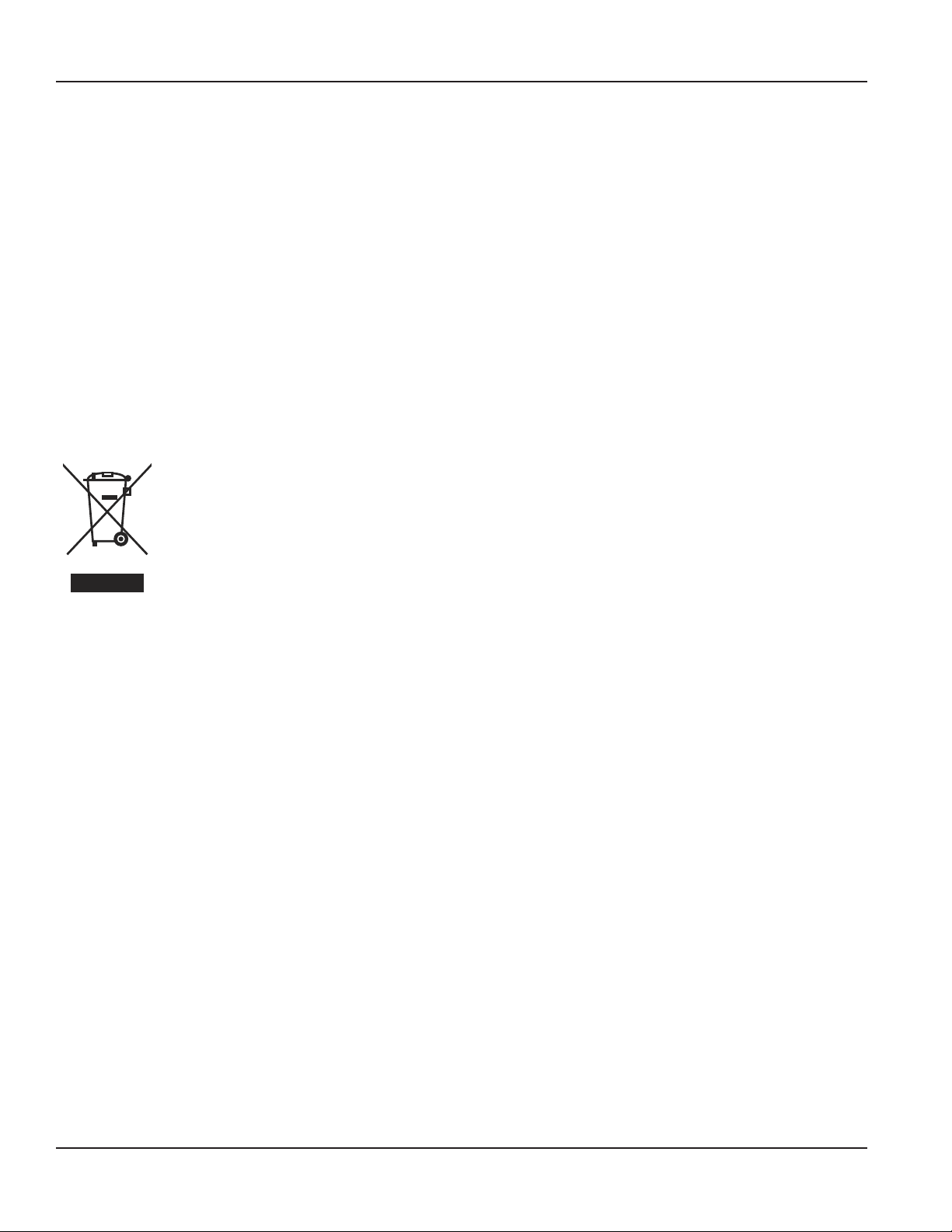
In the European Union, this label indicates that this product should not be disposed of with household
waste. It should be deposited at an appropriate facility to enable recovery and recycling.
For information on how to recycle this product responsibly in your country, please visit:
www.badgermeter.com
Page 18 June 2014
Page 19

User Manual
Page 19 June 2014
Page 20

A S
C C
®
Trademarks appearing in this document are the property of their respective entities.
Due to continuous research, product improvements and enhancements, Badger Meter reserves the right to change product or system specications without notice, except to the
extent an outstanding contractual obligation exists. © 2014 Badger Meter, Inc. All rights reserved.
[email protected] | www.wycotool.com
Phone: 262-639-6770 | Fax: 262-639-2023
Wyco Tool | 8635 Washington Avenue | Racine, WI 53406-3738 USA Legacy Document Number: 01-VBR-UM-00379-EN
 Loading...