

Wunder Bar S2.5 Installation Manual
POST-MIX
BEVERAGE
DISPENSER
For 1 to 14 Button
Post-Mix
and
Juice Dispensers
Standard and Flow Regulator Manifold
CONTENTS PAGE NUMBER
Installation..........................................................................................
Brixing…..............................................................................................
Configuration and Maintenance........................................................
Repair…...............................................................................................
Buttons and Butterfly Plates.............................................................
Butterfly Maps....................................................................................
Flow Regulator Manifold....................................................................
Sanitizing and Cleaning………………………………………………….
Troubleshooting…………………………………………………………..
Exploded Parts Drawings……………………………………………….
Copyright 1988, 2008 by Automatic Bar Controls, Inc.
SERVICE AND FACTORY ASSISTANCE:
Please record your Installer/Service Agent's name and phone number here for future reference:
SERVICE AGENT NAME: ___________________ DATE OF INSTALLATION: _______________
SERVICE AGENT PHONE: ___________________ SERIAL NUMBER: ______________________
Or, call the Wunder-Bar Service Hotline 1-866-WUNDERBAR (1-866-986-3372) anytime or
(707) 448-5151 Monday through Friday, 7:00 AM to 5:00 PM Pacific Time.
POSTMIX
2
3
4
5-6
7
8-9
10
11-12
13
14-23
3016449
CONFORMS TO
NSF STD 18
COMPONENT
REV120508
www.wunderbar.com
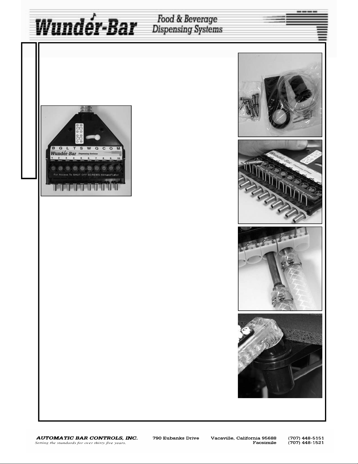
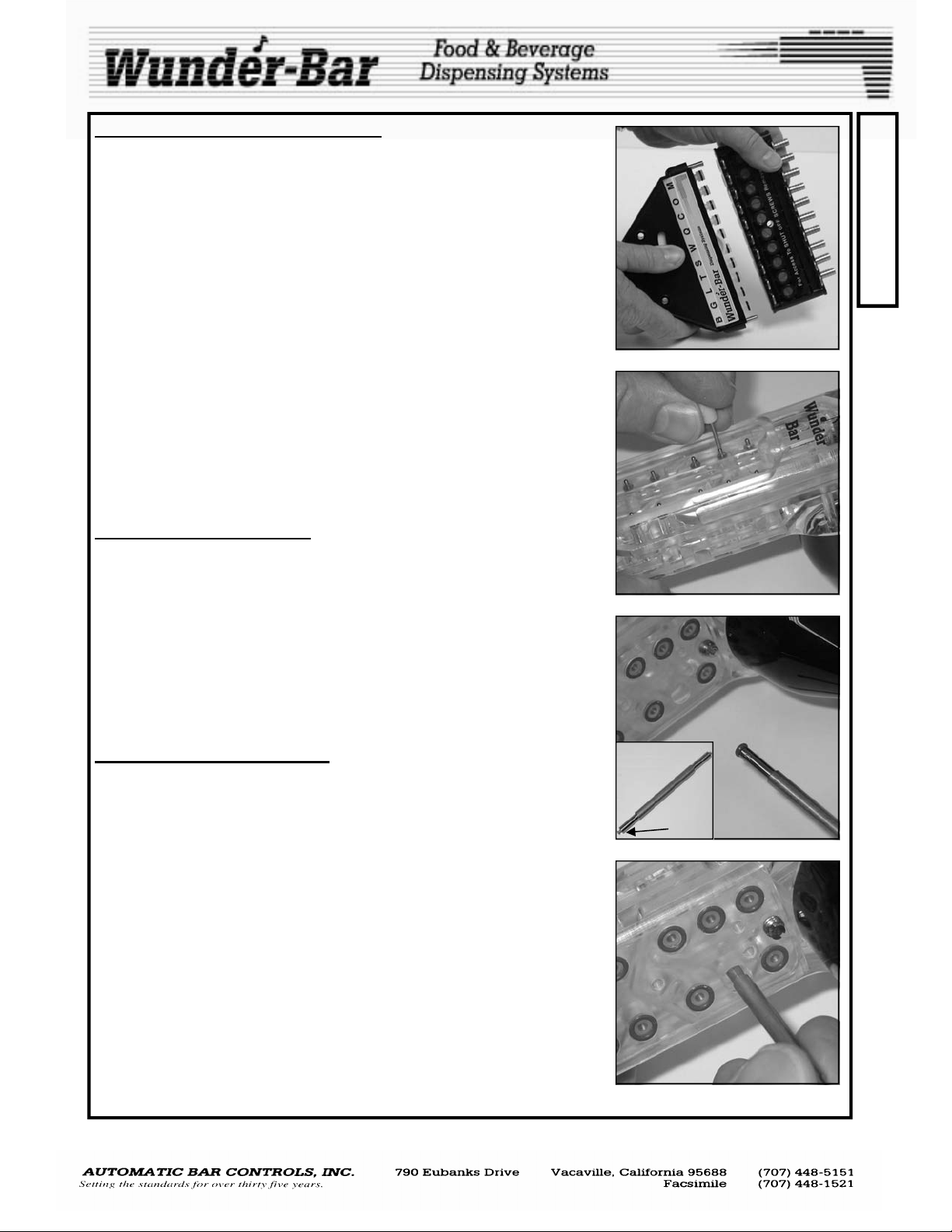
When you begin to install your Wunder- Bar® Mechanical Flex Hose bar
I
dispenser, you will notice that all necessary mounting hardware, a hose
hanger, a drip cup, a drain tube, and the appropriate number of stainless
N
steel input fittings are included with each dispenser (Fig.1).
S
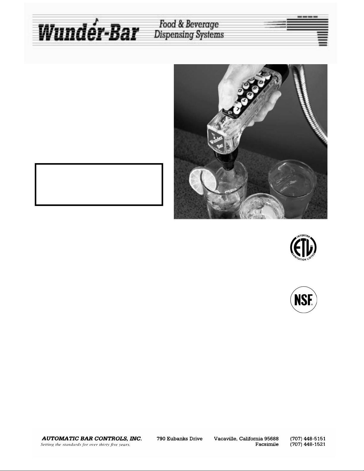
The input fittings are installed in the product manifold of the dispenser.
T
These input fittings are held in place by kwik klips. To remove input fittings,
pull up on kwik klip just far enough to allow removal of the fittings (Fig.2). (It
A
is not necessary to remove the kwik klip entirely).
L
L
A
T
I
O
N
When making your tubing connection; remove the input fitting, secure to
tubing with crimp ferrule or Oetiker clamp, re-install fitting into correct position on product manifold, push the kwik klip securely into place, locking input fitting into position. The letters on the product label at the manifold correspond to the button positions on the dispensing handle.
Two, 2" stainless steel wood screws are provided as part of the mounting
hardware package to attach the tube collector/manifold assembly to the
underside of the bar. (A Kwik Mount kit is also available as an optional
item). Attach the tube collector/manifold assembly to the underside of the
bar. It is recommended that a screw be placed in both the tube collector
and the brix manifold to prevent unwanted flexing.
Attach the hose hanger in proper position with the 3/4" stainless steel
screws provided. The hose hanger is in proper position when the slight
bend in the hose hanger slants down and WUNDERBAR can be read from
the top. The ribbed side of the hose hanger points down. Pull the drip cup
through the large opening in the hose hanger until is it securely in place.
The drip cup is in proper position when the hose hanger is in the middle
groove of the drip cup. Attach the drip cup drain tube to the drip cup outlet
and then route the drain tube’s end to a floor drain or other appropriate
sanitary drain opening. Do not install the drain tube’s end into the ice bin or
sink drain fitting. Most municipal, county, and state health departments require that this drain tube run directly to floor or sanitary drain opening.
CHECK YOUR LOCAL HEALTH CODES!
After all connection are made, turn on water supply, carbonator, C02, and
BIB pumps. CHECK ALL DISPENSER AND SYSTEM FITTINGS CONNECTIONS FOR LEAKS IMMEDIATELTY!
1/4” straight Input Fittings are included
with all new Wunder-Bar® Post-Mix
Beverage and Juice Dispensers unless
custom “Fitting Sets” are ordered. Input fittings are available in straight, 90
degree, and 45 degree configurations
with either 1/4”, 5/16”, 3/8", or 1/2"
barbed ends. 3/8” and 1/2” Input Fittings are available in two lengths:
“short” and “long” (Fig.3) to allow the
two lengths to be installed “staggered”
to accommodate braided tubing.
Fig.1
Fig.2
Fig.3
Fig.4
ATTENTION!
The POST-MIX DISPENSER’S water supply line must be connected to the potable water supply with
adequate backflow prevention to comply with federal, state, and local codes.
POSTMIX REV120508
2
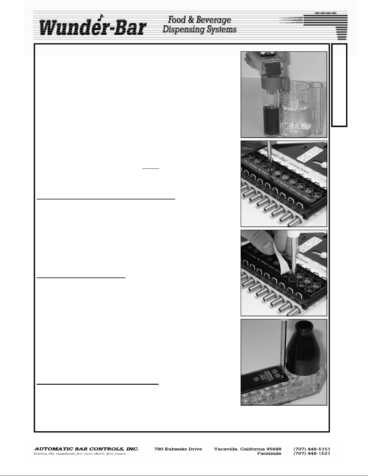
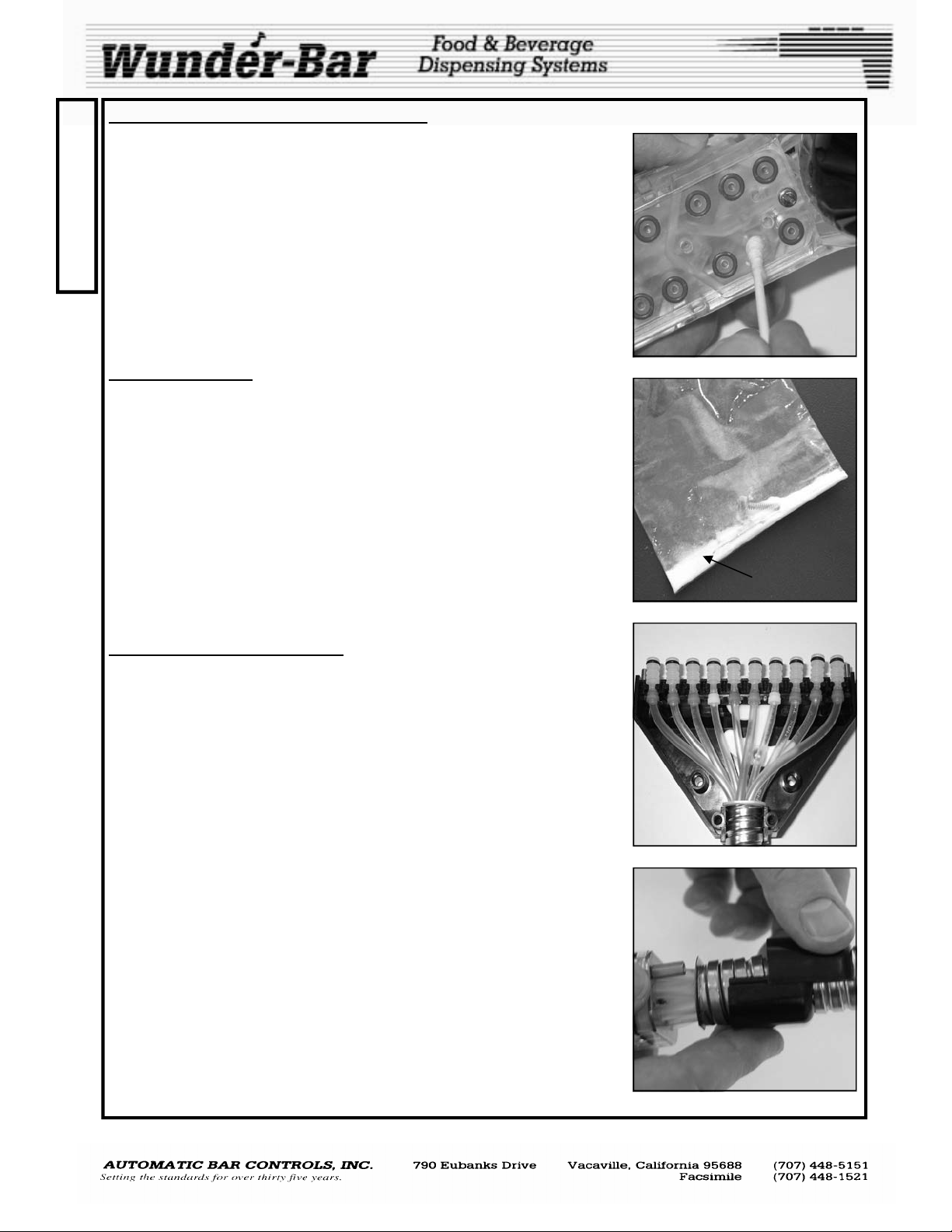
It will be necessary to brix your Wunder-Bar® Mechanical Flex Hose bar
dispenser before use. Either a Wunder-Bar® Syrup separator and Brix Cup
(Fig.5) or a refractometer may be used. Diet products do not contain sugar
so a syrup separator must be used in conjunction with a Brix Cup.
Brix is the amount of sugar content in a finished product. A syrup separator
(p/n PH10-83) is designed to separate the syrup/concentrate from the soda
or plain water, allowing for proper measurement of products. A Brix Cup
(p/n PH10-35) allows the user to visually compare and confirm the ratios of
soda-to-syrup and water-to-syrup. A refractometer (Not available from
Wunder-Bar) is a hand-held optical device used to measure the amount of
sugar in solution in beverages containing sugar.
In order for accurate Brix measurements or readings to be made, it will be
necessary to "ice down" the cold plate, by covering the cold plate located in
the bottom of the ice bin with a minimum of 4” to 6” of ice. If a mechanically
refrigerated beverage chilling system is to be used, instead of a cold plate,
turn ON the refrigerated, re-circulating beverage unit and allow it to “chill
down” to normal operating temperature before
ings or measurements. Once the cold plate or refrigerated unit have
reached temperature, dispense approximately 10 to 12 ounces of each beverage just before attempting to “read” each products’ brix.
SETTING THE SODA AND WATER FLOW RATES
Set the flow rate to your specifications or to the nominal flow rate of 5 oz of
soda in 3 seconds. Dispense Soda, through nozzle, into the large chamber
of the Brix Cup or a measuring cup. Adjust the brix screw at the "S" position on the product manifold by turning the screw counter-clockwise or
“out” to increase flow rates and clockwise or “in” to decrease flow rates
(Fig.6). The brix screws are the exposed screws on the product manifold.
Do not adjust the “Shut-Off Screws”! The shut off screws are closest to the
input fittings side of the manifold and are covered with a label that reads:
"FOR ACCESS TO SHUT OFF SCREWS REMOVE LABEL". (Fig.7) Do not
confuse the two different screws! Repeat adjustment process for the Water.
ADJUSTING THE BRIX RATIOS
Now that soda and water flow rates are set, product brixing may begin. The
"L" button corresponds to the "L" position on the product label at the manifold. "C" is for the "C" position, "T" for "T", etc. The syrup brix screws are
adjusted in the same manner as Soda and Water Brix Screws; counter-
clockwise or "out" increases flow rates, clockwise or "in" decreases
flow rates. The most common ratio for Post-mix beverages is 5:1 (5 parts
soda or water to 1 part syrup). However, some specialty beverages have
5.5:1 or higher ratios. Some juices and mixers have ratios as low as 1:1 to
2:1. Always read the BIB (Bag-In-Box) syrup container label for ratio specifications before starting. The small chamber (syrup side) of brix cup should
fill to 1 oz. in the same amount of time it takes to fill the large chamber 5 oz.
of soda or water—confirming a 5:1 brix ratio (Fig.5). If the product was 4:1
ratio, the small chamber would fill to the same 1 oz. mark, but the soda or
water would fill to 4 oz. Repeat until all products are brixed.
SECONDARY WATER BRIX SCREW (Fig.8)
All Wunder-Bar® Post-Mix and Juice dispensers have a “Secondary Water
Adjustment Screw” to enable juices and beverages with 2:1 and 1:1 ratios
to be dispensed through buttons located under the lower right Butterfly
Plate. The Secondary Water Brix Screw is factory set to the “open” position. Use a small bladed screwdriver to turn the screw Clockwise or “in” to decrease water flow to achieve 2.1
to 1:1 ratios for products like tomato juice and Bloody Mary Mix.
attempting to take Brix read-
Fig.5
Fig.6
Fig.7
Fig.8
B
R
I
X
I
N
G
POSTMIX REV120508
3
Wunder-Bar® Mechanical Post-Mix Dispensers can be configured for any
C
combination of carbonated, non-carbonated, or non-carbonated premix
products—up a total of 14 products total, including soda and plain water.
O
All these combinations are field convertible without shutting off the dis-
N
penser. Wunder-Bar® Post-Mix Juice Dispensers are permanently factoryconfigured to dispense non-carbonated juices, mixes, and beverages, only.
F
BUTTONS AND BUTTERFLY PLATES
I
The Buttons and Button Plate can be removed while dispenser is under
G
pressure (Fig.9). After the button plate has been removed, buttons and the
configuration of the dispenser can be changed so that any combination of
U
carbonated and non-carbonated buttons can be achieved. Simply remove
the butterfly retainer screws (Fig.10) and lift out the butterfly plates (stain-
R
less steel plates with small ball bearings attached) to create various stan-
A
dard configurations and endless special configurations. The butterfly plate
balls fit into the handle recess. The half moon cutout area of the butterfly
T
plates are where the retainer and retainer screws are located when attach-
I
ing the plates to the handle. When replacing the butterfly plates, be careful
not to over-tighten the retainer screws. This may cause the plates to bind.
O
See Butterfly Maps on pages 8 and 9.
N
SHUT OFF SCREWS
If it becomes necessary to work on the internal components of the dis-
A
penser, you must turn off all syrups, water, and carbonated water. Then
press all buttons to de-pressurize the dispenser. If the dispenser is ha s a
N
disconnect type manifold (Fig.11-13), this will be an easy task. Simply shut
D
down the one station, while the others remain in operation. If the dispenser
is equipped with a permanent manifold type, you must shut down the entire
M
beverage system and turn off the water and CO2. The difference between
a disconnect manifold and a permanent manifold is that the disconnect
A
manifold is equipped with shut off screws (Fig.11), which allow the dis-
I
penser to be shut off at each dispenser’s brix manifold without effecting the
other dispensers. Permanent manifolds do not have shut off screws.
N
The Shut off screws work like a gate valve. There is a hole through the
T
screw that runs in the same direction as the slot on the head of the shut off
screw. The shut off screws are under the label that reads: “FOR ACCESS
E
TO THE SHUT OFF SCREWS REMOVE THIS LABEL”. The shut off
N
screws are the Screws closest to the input fittings. (Fig.11) Turn the screws
90 degrees clockwise to shut off the flow of products to the dispenser. Shut
A
off screws do not shut off 100% and pressure will slowly build up in
the flex hose tubes if left attached. This will cause problems while work-
N
ing on the handle so be sure to disengage the flex hose from the brix block
C
for service to the bottom of handle.
E
DISCONNECTING DISPENSER FROM BRIX MANIFOLD
After all shut off screws are turned off depress buttons on dispensing handle to release pressure in the flex hose tubes. Pull up on kwik klips between the tube collector and manifold (Fig.12). These are called the Interconnect kwik klips. (It is not necessary to remove the kwik klips). By lifting
up all interconnect kwik klips and pushing the cam knob, the tube collector
separates from the brix manifold (Fig.13). A replacement dispenser can
now be placed onto the brix manifold, the interconnect kwik klips pushed
back into place, shut off screws opened 90 degrees counter clockwise, and
the new dispenser doesn't even have to be rebrixed! OR
made in a properly equipped, adequately lighted area, and out of the way of the bartender. Reinstall the dispenser back onto the brix manifold when repairs are completed. Re-brixing should not be required.
repairs can be
Fig.9
Fig.10
Fig.11
Fig.12
POSTMIX.pub REV120508
4
REPLACING O-RINGS IN THE HANDLE.
DO NOT attempt to make repairs, of any kind, while the dispenser is connected to the manifold. After all shut-off screws have been turned 90 degrees to the OFF position, use a screwdriver to move all of the tube collector Kwik Klips to the “un-locked” position (Fig.12). Separate the flex-hose
assembly from the manifold (Fig.13).
Remove the button plate. The butterfly plates may only need to be removed if a soda or water valve needs to be serviced. Otherwise, it will not
be necessary to remove the butterfly plates.
" ,
Remove the bottom plate screws and bottom plate. Hold the dispenser in
the palm of your hand with the nozzle pointing down. Push the desired
plunger stem, from the top of the dispenser, downward into the palm of
your hand, using a spare plunger stem, or a device the same diameter as
that of the plunger stem (Fig.14, paper clip, drill bit, etc.). The hat, valve
spring and valve plunger assembly drop out into your hand. Some models
may have a stem spring.
The Hat o-ring seals off bottom access hole of the valve cavity. The valve
spring (also known as the hat spring) provides sufficient tension to return
the plunger when button is not depressed. The stem o-ring seals around
the plunger stem in the top of the handle. (See exploded Handle parts
drawings for these various parts on pages 14, 17, 19, and 22).
REMOVAL OF STEM O-RING '. ' , . . . ',. ". . .../
The stem o-ring is still in the cavity of the dispensing handle. This o-ring
cannot be removed from the top of the handle. It must be removed from
the bottom of tile handle. Turn the handle so that the nozzle is pointing up.
Using the O-ring tool (p/n PH10-36) in your service kit, remove the stem oring with the “harpoon” end of the tool (Fig.15), (there are two ends to this
tool, one is barbed or harpoon shaped and the other is blunt). Stab the oring with this tool, and it will slide onto the tool, making removal fast and
easy. If you do not have this tool, straighten out a paper clip and put a
slight bend on one end. Insert it up into the hole of the O-ring and withdraw the o-ring from the handle. Be careful, not to gouge or scratch the oring seat with the end of the paper clip.
REPLACING THE STEM O-RING
Using the opposite end of the o-ring tool, (the blunt end), place the replacement o-ring onto the end of the tool and push the o-ring into place.
Make sure the o-ring is lubricated with Dow Coming food grade silicone
lubricant supplied with your parts kit. If you do not have this material, you
must use a suitable food grade silicone lubricant product. At this point
you must be careful! Push the o-ring very gently up into its seat (Fig.16).
As you push slowly and gently, you will pass an access hole. Rock the Oring back and forth, as you go, so that the side of the O-ring does not catch
on the edge of the side of the access hole. If you are not careful; you will
cut the O-ring as you go by this side hole. After you have the o-ring all the
way up into its seat, inspect the cavity to see if there are any o-ring shavings left behind. If so, you have damaged the O-ring and will have to repeat the removal of the stem o-ring. .If you do not have the O-ring insertion
tool, use the sank end of a drill bit. We recommend using a drill size of
#24, 25, or 5/32”. Be sure the stem O-ring is correctly and fully seated in
the upper cavity. If it should become crooked or cocked and not remain in
the seat, remove and insert a new O-ring.
PH10-36
harpoon end
Fig.13
Fig.14
Fig.15
Fig.16
R
E
P
A
I
R
POSTMIX REV120508
5
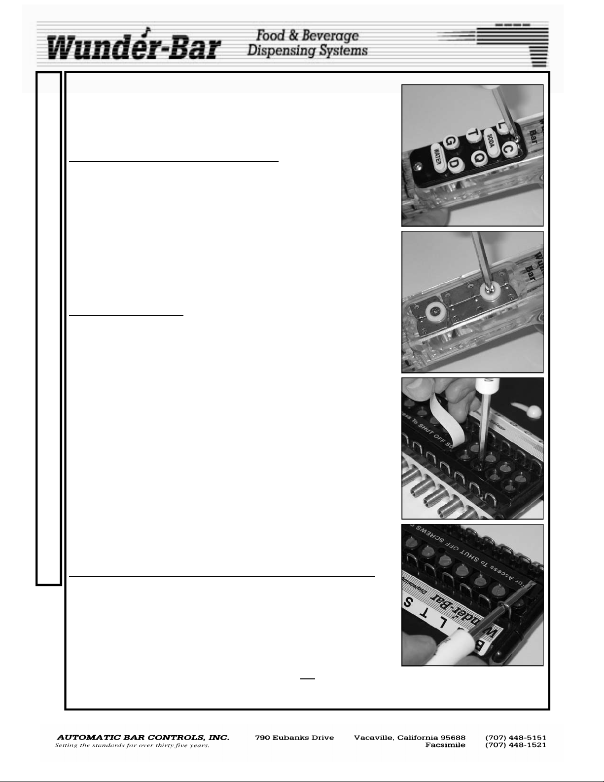
REPLACING VALVE PLUNGER ASSEMBLY
R
Replace the (cream colored) molded Santoprene® rubber valve plunger
assembly back into handle, being careful to align in cavity before pushing
E
the valve’s stem through the stem o-ring. Wipe the inside wall of valve cav-
P
ity clean and dry with a Q-tip (Fig.17). This is a very important step! Make
sure the inside wall is clean and dry! Pick up the hat and valve spring as-
A
sembly. Wipe the Hat o-ring carefully, while rotating the spring on a clean,
I
dry towel. Push into handle with the tip of the index finger. Leave finger tip
positioned over the o-ring until you are sure it does not back out of the cav-
R
ity. If hat and o-ring stays in place, immediately replace the bottom plate. If
the hat pops out, roll the hat o-ring assembly in baking soda (Fig.18,
white powder included with parts kit) and try again. If this fails, change
the Hat o-ring. Replace bottom plate. Do not over-tighten the bottom
plate screws as permanent damage to the handle may result.
TUBE COLLECTOR
When the tube collector is apart from the brix manifold, the tube collector
cover plate can be removed exposing the product tubing (Fig.19). The
three tubes at each outer position are large ID (six total), faster flow tubes,
for heavy syrup or juice products. The interconnect fittings for the large
tubes have the letter “B” molded into the base of every fitting. These tubes
are attached to the dispensing handle in the four lower (back of handle)
product inlet positions, which have larger tracks through the handle providing greater flow rates. The two blue colored tubes are the high pressure
tubes used for soda and water. The remaining tubes are standard ID tubes.
Both the blue tubes and the standard syrup tubes have smaller Interconnect fittings with the letter “A” molded into the base of every fitting. Red lock
Rings are used to secure the large ID syrup tubes and the blue tubes to
their “B” interconnect fittings. White Lock Rings are used to secure the
standard ID tubes to “A” interconnect fittings.
REPLACING A PRODUCT TUBE
Disconnect the Handle and sheathing assembly from the manifold. Remove the Tube Collector Cover screws to gain access to the tube-ends and
interconnect fittings. Lift up on the desired tube’s interconnect fitting and
unsnap it to separate it from the tube collector. The Individual tube can now
be replaced in the field. Remove the four screws from the handle heel and
slide the heel and sheathing away from the handle. Loosen and remove
the two retainer posts, using a hex driver, wrench, or pliers, from the rear of
the handle. NOTE: The word “UP” is stamped into the retainer plate at the
top to aid proper tubing to handle orientation during re-assembly. Pull the
retainer plate and tubing (with ferrules and caps) away from the handle.
A new tube assembly with an, interconnect fitting and lock ring attached,
would be ordered from the factory. Cut the old interconnect fitting off of the
old tube. Tape the no fitting end of the new tube to the old tube-end. Locate the tube to be replaced—at the heel end of the sheathing—and slowly
pull the tube through the sheathing all the way to the back of the retainer
plate. Un-tape the tubes and discard the old tube. Insert the new tube’s
end through the open hole in the retainer plate about 1 to 1-1/2”. Dip the
tube end in hot water for 3 seconds and then install the ferrule into the tube
end. Install the ferrule cap onto the tube end with ferrule installed. Push all
of the tubes’ back to the retainer plate surface. Align the mark to the top of
the handle while inserting all ten tube ends with ferrules and caps back into
their o-rings in the back of the handle. Once all ten are properly inserted,
re-install the two retainer posts while visually confirming that all ten ferrule
caps are centered in their respective tube seal o-rings. Do not over-tighten
the retainer posts.
LARGE
SYRUP
Fig.17
Fig.18
baking soda
WATER
SODA &
SMALL
SMALL
LARGE
SYRUP
Fig.19
Fig.20
POSTMIX REV120508
6
The Wunder Bar Mechanical Flex Hose bar dispenser is available in 1, 2, 3, 4, 5, 6, 7, 8, 9, 10, 12, and 14
button models. All models can be configured for many combinations of carbonated, non-carbonated, noncarbonated premix products at any time. All of these combinations are field-convertible and can be modified
without shutting off the dispenser. All seven, eight, and nine button dispensers have all the necessary valves
and product tubes already installed into the dispenser, making the upgrade to up to ten buttons as easy as
adding buttons on the handle and input modules and input fittings at the manifold.
BUTTONS AND BUTTERFLY PLATES
The buttons and button plate can be removed while dispenser is under pressure. After the button plate has
been removed, buttons can be changed as can the configuration of the dispenser. By removing the butterfly
retainer and screws, and lifting out the butterfly plates (stainless steel plates with small ball bearings welded
to their underside) we can create Various standard configurations and endless special co nfigurations. The
butterfly plate balls fit into indentations in the handle recess. The half moon cut out area of the butterfly plates
are where the retainer and retainer screws are located when attaching the plates to the handle. When replacing butterfly plates, be careful not to over-tighten the retainer screws. Over-tightening the retainer
screws can cause the butterfly plates to bind. See the Butterfly Plate Maps on pages 8 and 9 of this manual.
EXPLANATIONOF MODEL NUMBERS
',_ _ _
_' ,'-
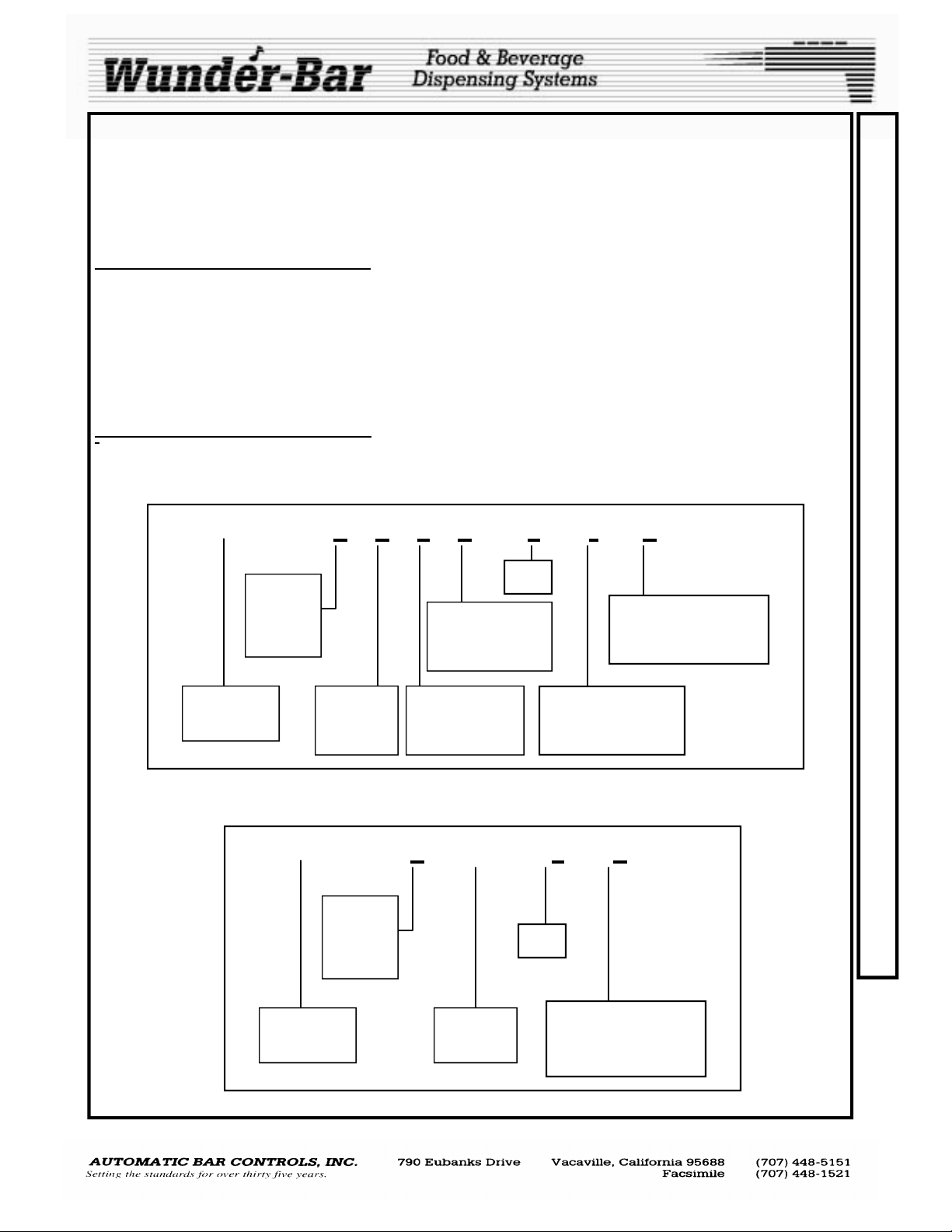
POST-MIX AND ENERGY DRINK DISPENSERS
WBM - a b c d — e — f - g
Total
Number
of Buttons
1 to 14
Number of
Non-Carbonated
Pre-Mix Products
Color
Diffuser / Nozzle Type
No letter = Series II
2.5 or III—Twist Lock
Wunder-Bar
Mechanical
Number of
Carbonated
Products
Number of
Non-Carbonated
Products
Manifold Type:
No Letter = Standard
FR = Flow Regulator
POST-MIX JUICE DISPENSERS
WBM - a - JD — e — g
C
O
N
F
I
G
U
R
A
T
I
O
N
A
N
D
M
O
D
E
L
N
U
M
B
Total
Number
of Buttons
1 to 12
Wunder-Bar
Mechanical
POSTMIX REV120508
Juice
Dispenser
7
Color
Diffuser / Nozzle Type
No letter = Series II
2.5 or III—Twist Lock
E
R
S
 Loading...