

Page 1

Manual
Com-Server++
Com-Server 3x Isolated
Release 2.08, November 2015
Typ 58665, 58662
Firmware 1.35 or higher
SN 2283238 or higher
W&T
Page 2

W&T
© 11/2015 by Wiesemann und Theis GmbH
Microsoft, MS-DOS, Windows, Winsock and Visual Basic
are registered trademarks of the Microsoft Corporation.
ST is a registered trademark of AT&T Lightguide Cable Connectors.
Subject to error and alteration:
Since it is posssible that we make mistakes, you mustn’t use
any of our statements without verification. Please, inform us
of any error or misunderstanding you come about, so we can
identify and eliminate it as soon as possible.
Carry out your work on or with W&T products only to the extent that they are described here and after you have completely read and understood the manual or guide. We are not liable
for unauthorized repairs or tampering. When in doubt, check
first with us or with your dealer.
Page 3

W&T
Introduction
The Com-Server++, 58665 and Com-Server 3x Isolated, 58662
represent a uniform platform for linking serial interfaces such
as RS232, RS422/485 to TCP/IP networks. The standard modes for transparent tunneling of serial data (e.g. through virtual COM ports) are implemented. The Com-Server++ includes
additional protocols and modes (e.g. UDP, TCP client, FTP client/server, etc.) as well as expanded functions for structuring
the data interchange.
In addition to all the standard applications implemented in
the firmware, this reference manual also describes the integration possibilities for your own applications.
Page 4

W&T
Content
1 Quickstart ���������������������������������������������������������������� 9
1.1 Flow chart – Network installation using WuTility ............... 10
1.2 Overview of configuration menu ...................................... 11
1.3 Factory defauls settings ................................................... 12
2 Assigning the IP address ��������������������������������������� 13
2.1 Configuring network parameters with WuTility ................. 14
2.2 Assigning the IP using DHCP protocol .............................. 17
2.2.1 Manual activation of DHCP ..........................................17
2.2.2 System name ..............................................................18
2.2.3 Lease time ..................................................................18
2.2.4 Reserved IP addresses .................................................19
2.4.5 Dynamic IP addresses .................................................19
2.3 Assigning the IP using the ARP command ........................ 20
2.4 Assigning the IP using the serial port ............................... 23
2.5 IP Address Conflict Detect ................................................ 25
3 Supply voltage ������������������������������������������������������� 27
3.1 Supply voltage 58665 ...................................................... 28
3.1.1 Power over Ethernet ....................................................28
3.1.2 External supply ...........................................................28
3.1 Supply voltage 58662 ...................................................... 29
4 Network interface �������������������������������������������������� 31
4.1 Ethernet interface ............................................................ 32
5 The serial combi-port ��������������������������������������������� 35
5.1 Overview .......................................................................... 36
5.1.1 Opening the Com-Server .............................................36
5.1.2 Mode selection ...........................................................36
5.2 RS232 mode (factory default) ........................................... 37
5.3 RS422/485 mode ............................................................. 38
6 LED displays ���������������������������������������������������������� 41
6.1 LED displays .................................................................... 42
7 Configuration access to the Com-Server ����������������� 45
7.1 Configuration menu structure .......................................... 46
7.2 Configuration via Telnet................................................... 48
7.2.1 Navigation within the Telnet menu ..............................48
7.3 Configuration via Browser - Web Based Management ........ 50
7.3.1 Activating WBM with the WuTility-Tool ........................50
7.3.2 Activating WBM via the serial interface ........................50
7.3.3 Activating WBM from the configuration menu..............51
7.3.4 Starting and navigating the WBM .................................52
Page 5

W&T
Subject to error and alteration
8 The basis configuration of the Com-Server ������������ 55
8.1 Save your settings ............................................................56
8.2 Menu: INFO System
8.3 Menu: SETUP System ........................................................ 58
.......................................................... 57
8.3.1 Menu: SETUP System r Setup TCP/IP...........................58
8.3.2 Menu: SETUP System r System Password ....................62
8.3.3 Menu: SETUP System r System Name
8.3.4 Menu: SETUP System r Logfile
8.3.5 Menu: SETUP System r Flash Update
8.3.6 Menu: SETUP System r Factory Defaults
..........................63
....................................63
...........................65
.....................65
8.3.7 Menu: SETUP System r Reset ......................................65
8.3.8 Menü: SETUP System r Link Speed
8.4 Menu ... r TCP/IP Mode r System Options ......................67
..............................65
9 Configuration of the serial port ����������������������������� 69
9.1 The serial parameters (Menu: UART Setup) ....................... 70
9.1.1 Baud rate, Data bits, Stop bits, Parity ..........................70
9.1.2 The handshake modes
................................................71
9.1.3 Receive Buffer (InQueue) .............................................75
9.1.4 FIFO Send/Rec (only Com-Server 3x Isolated) ..............75
9.2 TCP-/UDP port numbers (Menu: TCP/IP Mode) .................. 77
10 Packetizing serial datagrams ��������������������������������� 79
10.1 Packet Options ...............................................................80
10.1.1 Startsequence/Endsequence .....................................81
10.1.2 Startsequence + Lengthfield
10.1.3 Interpacket Delay
10.1.4 Fixed Packet Length
......................................................86
..................................................87
......................................84
11 Mode TCP-Server ���������������������������������������������������� 89
11.1 The Com-Server as TCP server .......................................90
11.1.1 Configuration of the local port number .....................91
11.1.2 Optional settings
12 Mode TCP Client ����������������������������������������������������� 95
12.1 The Com-Server as TCP client .........................................96
12.1.1 TCP client mode with fixed destination system .........97
12.1.2 TCP client mode with serial addressing
12.1.3 Optional settings ....................................................102
12.1.4 Deactivating TCP client mode
12.1.5 Application: Client/Server mode
13 Data transfer per UDP ������������������������������������������ 109
13.1 Der Com-Server als UDP-Peer .......................................110
13.1.1 Setting the local UDP port number ..........................111
13.1.2 UDP clientmode with fixed destination system
13.1.3 UDP client mode serial addressing
13.1.4 Optional settings ....................................................115
......................................................91
...................100
..................................105
..............................105
........112
..........................113
5
Page 6

W&T
13.1.5 Deactivating UDP mode ...........................................116
14 UDP Bus Mode ������������������������������������������������������ 117
14.1 Function of UDP Bus Mode ........................................... 118
14.1.3 Optional settings ....................................................120
14.1.4 Deactivating UDP mode ...........................................121
15 The Windows COM port redirector ����������������������� 123
15.1 Overview ......................................................................124
15.2 Download & installation of the W&T COM redirector ..... 125
15.2.1 Installation of the W&T COM port redirector ............125
15.2.2 Uninstalling the W&T COM Port Redirector .............126
15.3 Set up virtual COM ports .............................................. 127
15.3.1 Optional settings on the Com-Server .......................127
16 Box-to-Box mode ��������������������������������������������������� 131
16.1 Box-to-Box application ................................................. 132
16.1.1 Configuring Box-to-Box mode .................................133
16.1.2 Optional settings ....................................................134
16.1.3 Deactivating Box to Box Mode .................................136
17 Mode FTP-Server �������������������������������������������������� 139
17.1 The Com-Server as FTP server ...................................... 140
17.1.1 Activating FTP-Server mode .....................................140
17.1.2 Supported FTP commands and functiuons ..............141
17.1.3 Optional settings ....................................................142
18 Mode FTP-Client ��������������������������������������������������� 143
18.1 The Com-Server as FTP client ....................................... 144
18.1.1 Configuring the destination address port no. ..........145
18.1.3 FTP client with serial protocol .................................148
18.1.4 Closing the FTP connection .....................................150
18.1.5 Deactivating FTP client mode ..................................151
18.1.6 Application examples .............................................152
19 Mode Telnet Server ���������������������������������������������� 155
19.1 The Com-Server as Telnet server .................................. 156
19.1.1 Activating Telnet-Server mode ................................156
19.1.2 Optional Settings ....................................................157
20 Mode Telnet Client ����������������������������������������������� 159
20.1 The Com-Server as Telnet client ................................... 160
20.1.1 Destination address and port number .....................160
20.1.2 Optional settings ....................................................162
20.1.3 Deactivating Telnet client mode ..............................163
Page 7

W&T
21 Mode SLIP-Router ������������������������������������������������� 165
21.1 SLIP mode .................................................................... 166
21.1.1 Configuring the SLIP mode ......................................167
21.1.2 Optional settings ....................................................169
21.1.3 Deactivating SLIP router mode ................................169
21.1.4 Application example ...............................................170
21.1.5 Configuring the Com-Server via SLIP .......................171
22 OPC data transfer ������������������������������������������������ 173
22.1 Overview ......................................................................174
22.2 Download and installation of the W&T OPC server ........ 175
22.2.1 Installation of the W&T OPC server ..........................175
22.2.2 Deinstallation of the OPC server ..............................176
22.3 Configuration of the OPC server ...................................177
22.3.1 Optional settings on the Com-Server .......................177
22.3.2 Incorporating Com-Server into the OPC Server ........179
22.3.3 Structuring the serial data .......................................180
22.4 Serial OPC variables .....................................................181
23 Mode InQueueCopy ���������������������������������������������� 183
23.1 InQueue Copy .............................................................. 184
23.1.2 Configuring InQueueCopy .......................................185
24 Status and error messages ���������������������������������� 187
24.1 Menu Setup Port x r Port State .................................... 188
25 Expanded services of the Com-Server ������������������ 191
25.1 The control port...........................................................192
25.1.1 The control structure ..............................................193
25.2 Reset Com-Server port .................................................199
25.3 Com-Server reset .........................................................200
25.4 Up-/downloading configuration data
25.5 Inventory taking per UDP/8513
25.6 SNMP management ...................................................... 205
............................ 201
.................................... 203
26 Firmware-Update of the Com-Server ��������������������� 207
26.1 Where do I get the current firmware? ...........................208
26.2 Network firmware update under Windows .................... 209
Appendix ������������������������������������������������������������������� 213
Used ports and network security .......................................... 214
Serial assignment of the IP address under Windows .............218
WuTility - Inventory and management tool ...........................222
Hardware-Reset to factory defaults.......................................223
Technical data and formfactor 58665 ..................................224
Technical data and formfactor 58662 ..................................225
Index ������������������������������������������������������������������������� 226
Page 8

W&T
Page 9

W&T
Subject to error and alteration
1 Quickstart
Already experienced users of Com-Servers will find on the two following
pages a flow chart with the essential steps for start-up as well as a comple-
te overview of the configuration menu. Detailed information can be found
then in the following sections.
9
Page 10

W&T
1�1 Flow chart – Network installation using WuTility
Network
Com-Server
Select site
Connect
supply voltage
Connect
network cable
Obtain IP
address, subnet
mask, gateway
Windows PC
with TCP/IP
WuTility
installed?
yes
Start
WuTility
Select
device in
inventory list
Button:
IP address
Enter IP address,
subnet mask,
gateway
no
Install
WuTility with
product CD
Finish
10
Page 11
W&T
Subject to error and alteration
Packet Options
Fixed Packet Length
SETUP Port 1
SETUP Port 2
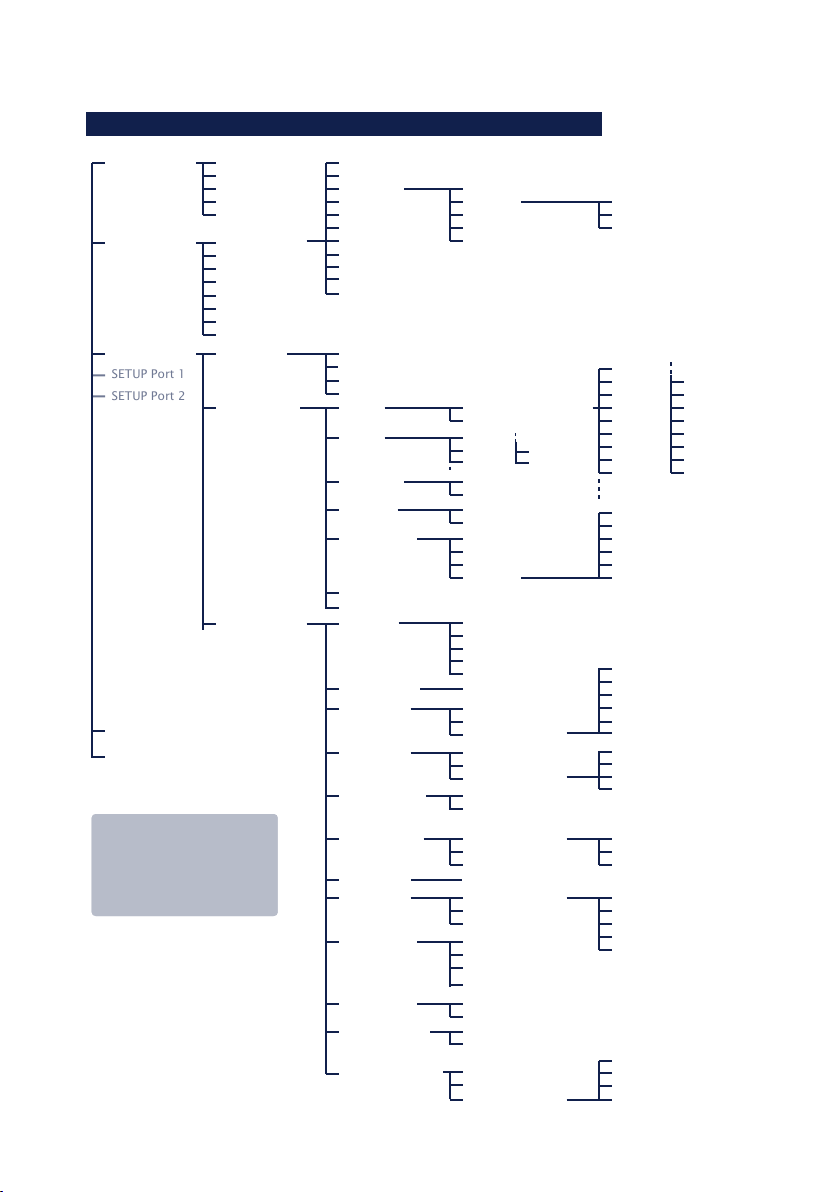
1�2 Overview of configuration menu
INFO System Cable Type
SETUP System Setup TCP/IP
SETUP Port 0
SAVE Setup
Logout
To activate the new settings
always save using SAVE Setup
with Telnet or the LOGOUT
link on the web pages. In WBM
use the link Logout and click
(1)
Factory defaults are printed bold
MAC address
SOFTW Date/REV
HARDW Rev
Run Time
System Password
System Name
Logfile
Flash Update
Factory Defaults
Reset
Link Speed (Auto, 10|100BT, HD|FD)
Port State
UART Setup
TCP/IP Mode
Save!
IP-Address (0.0.0.0)
Subnet Mask
Gateway
DNS-Server
MTU (560-1460)
DHCP Client
System Port List
Wake-on-LAN
Keep Alive Time 30s
Retransm. Timeouts
IP Address Conflict detect
Connection State
Byte counter
Error State
Clear Port Mode
Baud
Parity NONE
Data Bits
Stopbit
Handshake
Receive Buffer (InQueue): 32-4094 Bytes
Send/Rec FIFO
Port List
TCP Server
TCP Client
UDP Client
Telnet Server Activate yes/no
Telnet Client
FTP Server Activate yes/no
FTP Client
Box to Box
(TCP)
SLIP Router
InQueue Copy Local Copy Port
System Options
(1)
Standard Gateway (0.0.0.0)
Route 1
Route 2
Route 3
Route 4
Standard Baudrates
Special Baud Divisor
EVEN
ODD
8
7
1
2
None
Hardware
Software
Special
Local Port TCP/UDP
Controlport TCP
Telnet Port (TCP)
FTP Port (TCP)
Reset Port (TCP)
Activ. Packet Options
Server Port
Server IP/URL
Special Options
Server Port
Server IP/URL
Special Options
Telnet Echo
Server Port
Server IP/URL
Special Options
Server Port
Server IP/URL
Special Options
Server Port
Server IP
TLS(SSL) Encryption
Activ. Packet Options
Net Address
SLIP-Net Routing
Accepted Copy-Slave IPs
Network Delay
Flush Buffer
SPACE
MARK
Destination
Netmask
Gateway
230,4k
153,6k
115,2k
57600
38400
19200
9600
4800
Pin: RTS
Pin: DTR
Pin: CTS
Pin: DSR
XON/XOFF
XON/XOFF (Filter)
Activ. Packet Options
Inactivity Timeout
Connect. Timeout
Disconnect Char
Client: "C"+Addr
Response Mode
Activ. Packet Options
Client: "C"+Addr
Write: "C"+Addr
Disconnect Char
Disconnect Char
Inactivity Timeout
Serial 0d -> 0d00
Auto FTP
FTP Client Login
Inactivity Timeout
Connect. Timeout
Protocol Char
Start-/Endsequ.
Startsequ. + Length Filed
Interpacket Delay
2400
1200
600
300
150
110
757200
50
11
Page 12

W&T
1�3 Factory defauls settings
The list contains an overview of the most important settings.
For many applications, such as the W&T COM Port Redirector,
no additional configurations need to be made besides assigning the network base parameters. Detailed information on
the respective parameters can be found in later sections of
this manual.
Network settings
Hardware connection: Auto negotiating
IP address: 0.0.0.0
Gateway address: 0.0.0.0
Subnet mask: 255.0.0.0
DHCP: Active
To prevent unintended address assignments or
1
changes, we recommend deactivating the DHCP protocol
if it is not expressly used in the respective network environment.
Serial settings
Hardware connection: RS232
Baud rate: 9600
Data bits: 8
Parity: NO
Stop bits: 1
Handshake: None
Fifo: OFF
Configuration access
Per Telnet using TCP port 1111
Network applications / Operating mode
(suitable for use with W&T COM redirector)
TCP server ports, port no. A-C: 8000, 8100, 8200
Control port TCP, port no. A-C: 9094, 9194, 9294
12
Page 13

W&T
Subject to error and alteration
2 Assigning the IP address
The Com-Server is factory set to IP address 0.0.0.0. Before you can make
the entry in the Com-Server, you need to specify an IP address that is valid
for your network. Your system administrator will provide you with this. The
IP address must be unique within the network!
. ... using management tool WuTility
. ... using the ARP command
. ... using DHCP protokoll
. Assigning IP address, subnet mask and gateway address
through the serial port
. IP Address Conflict Detect
13
Page 14

W&T Assigning the IP address
2�1 Configuring network parameters with WuTility
WuTility is the central inventorying and management tool for
all W&T network devices. In addition to convenient assigning
of the IP parameters, WuTility also provides quick access to
device configurations, the ability to perform firmware updates, managing configuration profiles, etc.
WuTility can be directly installed from the included product
CD. Current versions are always available on our website at
http://www.wut.de. From there you can navigate using the
menu tree on the left side.
Products & Downloads r Com-Server r Software-Tools
After extracting the ZIP file you install WuTility by doubleclicking on the file wutility_***.msi. Start WuTility using
Start r All Programs r W&T Software Toolkit r WuTility
2�2�1 Applications and prerequisites
IP assignment using WuTility works regardless of the current
network parameters of the Com-Server and the computer
used. This means that even if the Com-Server does not have
IP parameters consistent with the respective network, WuTility
can be used to overwrite them. Likewise, WuTility can be used
to assign any values not consistent with the network the PC is
located in.
• The PC and Com-Server must be located in the same physi-
cal network. This means you cannot assign values through
a router.
• Any firewalls and network security packages installed on
the PC must allow communication between WuTility and
the Com-Server based on UDP broadcasts. If necessary
these must be correspondingly configured or temporarily
turned off.
14
Page 15

W&T Assigning the IP address
Subject to error and alteration
• If the Com-Server does not have its factory default settings
and there is a system password assigned, this must be
known in order to make changes using WuTility.
Step 1: Start the assignment dialog
WuTility automatically searches the local network for connected W&T network devices and creates an inventory list. This
search process can be repeated manually as often as desired
by clicking on the Scan button:
Within the inventory list you can identify the desired ComServer based on its MAC address. For initial installations its IP
address is 0.0.0.0.
Select the Com-Server and click on the IP address button:
15
Page 16

W&T Assigning the IP address
Step 2: Assign the IP parameters
The Static option allows you to assign fixed basic parameters
while simultaneously disabling DHCP and BOOTP protocols
in the Com-Server. Enter the desired values for IP address,
subnet mask and gateway address in the corresponding entry
fields. The DHCP option enables DHCP protocol in the ComServer, and operation with a static IP address is no longer
possible (see IP Assignment using DHCP Protocol for detailed
information)
If the remaining configuration of the Com-Server is done
using a Web browser, activate the option Web-Based-Management (WBM). If you are not using the standard HTTP port 80,
change the port number to the desired value.
Clicking on the Next button assigns the network parameters
to the Com-Server. After acknowledging the resulting message, all the columns in the WuTility device list are filled in
with information.
If necessary, the remaining configuration of the Com-Server
is done using Telnet or Web-Based-Management. Click on the
Telnet or Browser button.
Telnet:
Browser:
Additional information can be found in the section Configura-
tion Accesses for the Com-Server.
16
Page 17

W&T Assigning the IP address
Subject to error and alteration
2�2 Assigning the IP using DHCP protocol
DHCP protocol is activated by the factory default settings,
so that in network environments dynamic IP assignment is
sufficient for connecting the Com-Server to the network. The
following parameters can be assigned using DHCP:
• IP address
• Subnet mask
• Gateway address
2�2�1 Manual activation of DHCP
To prevent unintended address assignments or address changes, DHCP protocol is automatically deactivated when using
all other methods for assigning the IP parameters. The following methods are then available for later activation of DHCP.
• Management-Tool WuTility
Select the desired Com-Server from the device list and
click on the IP Address button. In the following dialog
check the option DHCP and then click on Next.
• Telnet-/WBM configuration
In the menu branch SETUP System r Setup TCP/IP r
DHCP Client you can activate DHCP protocol. For detailed
information, see the section Menu: SETUP System.
A set static IP address is deleted after DHCP is
1
activated and the associated automatic reset. The ComServer automatically sets this to 0.0.0.0 and starts sending
DHCP requests.
17
Page 18

W&T Assigning the IP address
2�2�2 System name
To support any automatic updating of the DNS system by the
DHCP server, the Com-Server identifies itself within the DHCP
protocol with its system name. The factory default setting for
this is COMSERVER- followed by the last three places of the
Ethernet address. For example the factory set system name of
a Com-Server with the Ethernet address 00:c0:3d:01:02:03 is
COMSERVER-010203. The system name of the Com-Server can
be changed in the configuration. For additional information
refer to the section Menu: SETUP System r System Name.
2�2�3 Lease time
The lease time determined and transmitted by the DHCP
server specifies the Time-To-Live of the assigned IP address.
After half the lease time has expired, the Com-Server attempts
to extend the time for the assigned DHCP server and up update the address. If this is not possible by the time the lease
time expires, for example because the DHCP server can no
longer be reached, the Com-Server deletes the IP address and
starts a new cyclical search for alternate DHCP servers for the
purpose of assigning a new IP address.
Because of the absent clock, the lease time associated with
the current IP address is no longer available after a reset.
After the restart therefore a corresponding update request
is issued with the original DHCP server. If the latter is not
resolvable at this point in time, the Com-Server deletes the IP
address and starts a new cyclical search for alternate DHCP
servers.
If DHCP is activated, the remaining lease time together with
the current IP address is displayed in the menu item SE-
TUP System r Setup TCP/IP r IP-Address using the format
hh:mm:ss.
18
Page 19

W&T Assigning the IP address
Subject to error and alteration
2�2�4 Reserved IP addresses
If the Com-Server is used as a TCP server or UDP peer, it
provides services which other clients in the network can
also make use of as needed. To open a connection, they of
course need the current IP address for the Com-Server, so
that in such situations it makes sense to reserve a particular
IP address for the Com-Server on the DHCP server. This is generally done by linking the IP address to the unique Ethernet
address of the Com-Server, which can be found on the sticker
attached to the housing.
EN = 00c0:3d01:0203
5xxxx [TB number
and/or model name]
OK +0123456789
Ethernet address
2�4�5 Dynamic IP addresses
Fully dynamic address assignment, whereby the Com-Server
gets a different IP address every time it is restarted or after
the lease time has expired, only makes sense in network
environments with automatic cross-connection between the
DHCP and DNS services. This means when a new IP address is
assigned to the Com-Server, the DHCP server then automatically updates the DNS system as well. The new address is associated with the respective domain name. If in doubt, consult
your system administrator for detailed information about your
network environment.
19
Page 20

W&T Assigning the IP address
2�3 Assigning the IP using the ARP command
Requirements
This method can only be used if the Com-Server does not already have an IP address, i.e. the entry is 0.0.0.0. To change
an IP address, use one of the other methods described in
this section or use the configuration menu over Telnet. If the
Com-Server has any other value, this access is disabled.
When the factory setting is in effect as well as after a manual
changeover from static to DHCP, the method for assigning
the IP described in this section functions only after a delay of
approx. 2 minutes after a reset or after power-up.
This method does not work across networks, e.g. through
routers. This means the PC and Com-Server used for assigning must be connected to the same physical network segment. Only IP addresses whose Net-ID is identical to that of
the assigning computer can be assigned.
To avoid unintended changes to the IP address, the
1
DHCP client of the Com-Server is automatically deactiva-
ted when configuring using a static ARP entry.
Step 1
Read off the
Ethernet address of the Com-Server from the stik-
ker on the side of the housing.
EN = 00c0:3d01:0203
5xxxx [TB number
and/or model name]
OK +0123456789
Ethernet address
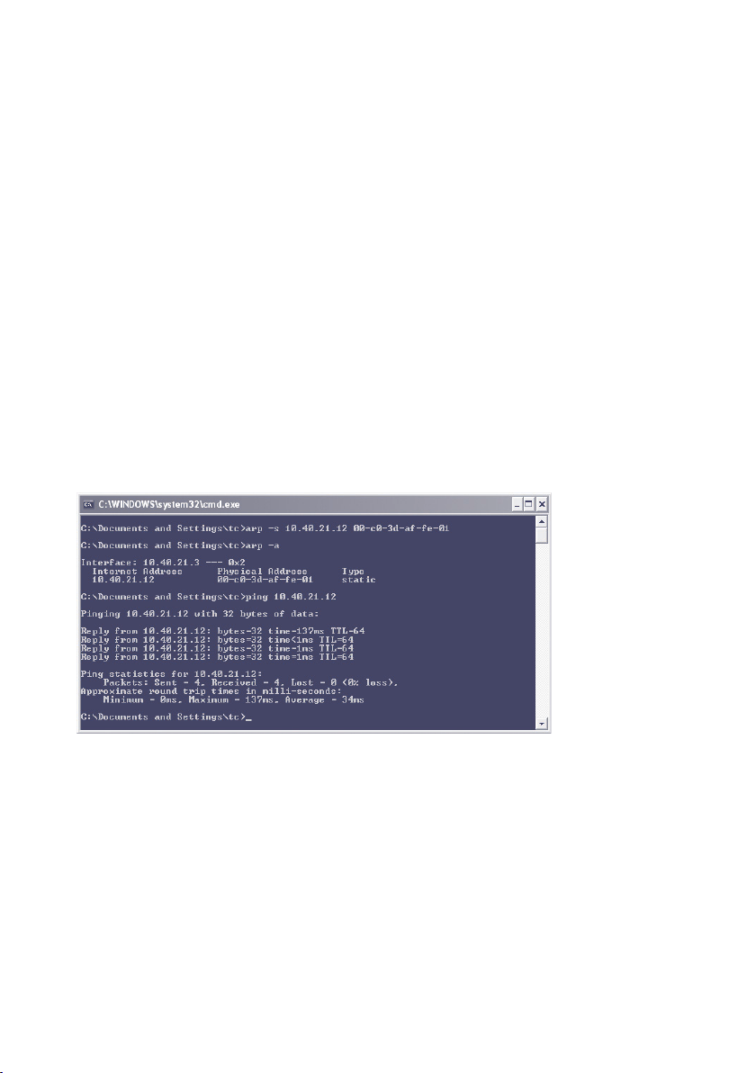
Insert a static entry into the ARP table of the computer using
the following command line:
arp -s [IP address] [Ethernet address]
20
i
Older Windows systems
only accept a static entry if there is a dynamic
one already present.
Here you should first
ping another network
station.
Page 21
W&T Assigning the IP address
Subject to error and alteration
E.g. under Windows:
arp -s 172.16.231.10 00-C0-3D-00-12-FF
E.g under UNIX/Linux:
arp -s 172.16.231.10 00:C0:3D:00:12:FF
The IP addresses must be without leading zeros in
1
all Windows environments. Otherwise the entry is incorrectly interpreted by the system and an incorrect IP address
is assigned to the Com-Server. In Windows Vista and newer
the prompt cmd.exe necessary for invoking the ARP command
must be started using Administrator rights.
Step 2
Use the following command line to ping the Com-Server with
the desired IP address:
ping 10.40.21.12
The Com-Server takes the IP address of the first network packet sent to it as its own and saves it in non-volatile memory.
The ping requests of the PC are then replied.
It is not possible to configure the subnet mask and gateway
address using a static ARP entry. These need to be set in a
21
Page 22

W&T Assigning the IP address
separate Telnet configuration session (see section Basic Configuration of the Com-Server).
22
Page 23

W&T Assigning the IP address
Subject to error and alteration
2�4 Assigning the IP using the serial port
After a Com-Server reset a time window of around 1-2 seconds is available on port A, during which you can assign a
new IP address, subnet mask and gateway address by entering at least 3 „x“.
In contrast to other methods described above, this serial method functions regardless of whether the Com-Server already
has an IP address or not. The procedure can be repeated as
often as desired. The appendix contains the detailed procedure under Windows.
Preparations/requirements
First connect the serial port A of the Com-Server to a computer. For a standard PC or laptop, you will need a crossed
RS232 cable (=Null modem cable, see RS232 mode).
Any serial terminal program can be used for assigning. The
following transmission parameters must be set regardless of
any other settings in the Com-Server:
9600 baud, no parity, 8 data bits, 1 Stop bit, no Handshake
Start the serial configuration mode
Reset the Com-Server by interrupting the power. While the
Com-Server is starting up, use the terminal program to send
the letter x at least three times. The COM-Server will then return the prompt IPno.+<Enter>:.
Assigning the IP settings
Use the usual format (xxx.xxx.xxx.xxx) to enter the IP
address, and end the entry by pressing <Enter>. If the entry was accepted, the acknowledgement is the assigned IP
address. Otherwise you will get a FAIL message followed by
the last current IP address.
Together with the IP address, the subnet mask and gateway
address can also be assigned serially. The entry is separated
23
Page 24

W&T Assigning the IP address
by commas and follows the IP address. Entering as shown in
the following example will assign IP address 172.17.231.99,
subnet mask 255.255.255.0 and gateway 172.17.231.52 to
the Com-Server
Exampel: Assigning the IP address:
IP no.+<ENTER>: <- Com-Server
172.17.231.99 -> Com-Server
Example: Assigning IP address, Subnet mask and gateway
IP no.+<ENTER>: <- Com-Server
172.17.231.99, 255.255.255.0,172.17.231.1 -> Com-Server
Option: Activating Web Based Management (WBM)
To further configure the Com-Server you can use either Telnet
protocol or an Internet browser, although only Telnet is an
option in the Com-Server as shipped from the factory. You
can activate Web Based Management as part of the serial IP
assignment. To do this, enter +w[Portno.] directly after the
IP address or address string. Here Portno. is the desired TCP
port in decimal format.
Exampel 1: Assigning the IP adress and WBM on Port 80.
xxx... -> Com-Server
IP no.+<ENTER>: <- Com-Server
172.17.231.99+w80 -> Com-Server
172.17.231.99-1 <- Com-Server
Exampel 2: Assigning IP address, subnet mask, gateway and
activating WBM on port 8800.
xxx... -> Com-Server
IP no.+<ENTER>: <- Com-Server
172.17.231.99,255.255.0.0,172.17.231.1+w8800 -> Com-Server
172.17.231.99,255.255.0.0,172.17.231.1+w8800 <- Com-Server
24
Page 25

W&T Assigning the IP address
Subject to error and alteration
2�5 IP Address Conflict Detect
Firmware version 1.31 and higher enables the Com-Server++
to detect and display an IP address conflict. This function is
deactivated by default and can be activated in the following
menu branch:
SETUP System
When the Com-Server is restarted there is an active check for
any address conflicts. During normal running the monitoring is passive. Details on this functionality can be found in
RFC5227, IPv4 Address Conflict Detection.
Indication of an address conflict
The Com-Server++ indicates a detected address conflict by
rapid flashing (approx. 3x/s) of the Error LED. In addition a
message including the competing MAC address is generated
in the Error State (Setup Port x r Port State r Error State).
When using a static IP address the conflict is only indicated.
The Com-Server continues to use this IP address. In a DHCP
environment the Com-Server informs the responsible DHCP
server, resets the IP address and waits for assignment of a
corrected IP address.
1
re inform the responsible administrator in such cases.
...
Setup TCP/IP
...
IP Address Conflict Detect
IP address conflicts generally lead to communication
problems which are difficult to diagnose. Please therefo-
25
Page 26

26
W&T Assigning the IP address
Page 27

W&T
Subject to error and alteration
3 Supply voltage
. Com-Server++
. Com-Server3x Isolated
27
Page 28

W&T Supply voltage
3�1 Supply voltage 58665
The model 58665 can also be operated either using PoE or
from an external power supply.
The current draw can be found in the technical appendix.
3�1�1 Power over Ethernet
In PoE environments (Power-over-Ethernet, IEEE802.3af) power
is provided by the network infrastructure. The Com-Server
supports both phantom power using data pairs 1/2 and 3/6
as well as power feed using the unused wire pairs 4/5 and
7/8.
The model 58665 is a device in PoE Power Class 1 (power consumption 0.44 to 3.84W).
3�1�2 External supply
As an alternative to PoE power supply the Com-Server can also
be powered by an external power supply connected to the
screw terminals on the underside of the housing. A half-wave
rectifier makes the input reverse polarity protected. AC or DC
power may be used, whereby the following limit values must
be observed:
• AC: 18Vrms (- 10%) - 30Vrms (+10%)
• DC: 12V (-10%) - 48V (+10%)
(before SN 2283238 24V (-10%) - 48V (+10%))
When powering with DC voltage polarity must be observed:
L+M
+12-48V DCGND
28
Page 29
W&T Supply voltage
Subject to error and alteration
3�1 Supply voltage 58662
The model 58662 Com-Server can be powered using the plugin screw terminal located on the lower section of the housing.
The input is reverse polarity protected and may be used with
AC or DC voltages having the following specifications:
The current draw can be found in the technical appendix.
• AC: 9Veff (- 10%) - 30Veff (+10%)
• DC: 12V (-10%) - 48V (+10%)
L+M
+12-48V DCGND
29
Page 30

30
W&T Supply voltage
Page 31

W&T
Subject to error and alteration
4 Network interface
. Ethernet interface
. 10/100BaseT autonegotiating
. Power-over-Ethernet
31
Page 32

W&T Network interface
4�1 Ethernet interface
The Com-Server++ incorporates an IEEE 802.3-compatible
network interface.
4�1�1 Link status
The Link status is indicated on the two LEDs built into the
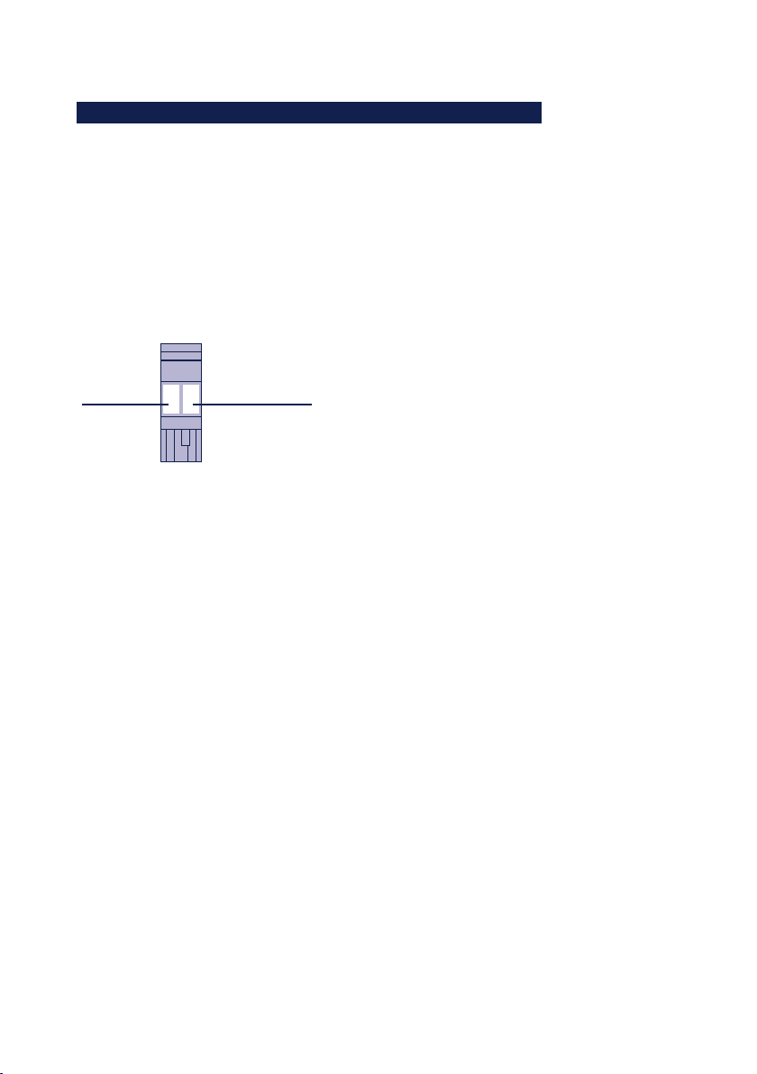
RJ45 jack.
• Link/Activity (green)
ON indicates a valid link to a hub or switch port. The LED
flashes when there is data traffic.
• Speed (yellow)
ON indicates a 100MBit/s-link (100BaseT). OFF indicates
10MBit/s (10BaseT)
4�1�2 10/100BaseT on RJ45
The Com-Server has a network interface on a shielded RJ45
connector. The pin assignments shown below correspond to
an Auto-MDI-X interface, so that the connection to the hub or
switch is made using a max. 100m long shielded patch cable.
1 2 3 4 5 6 7 8
Speed Link/
Activity
The network connection is galvanically isolated with respect
to the supply voltage as well as the serial interface(s) for at
least 1,5kV
rms
.
Auto Negotiation: 10/100BaseT, Full/Half Duplex
The Com-Server is factory set to operate in Auto-Negotiation
mode on the network side. The data transmission speed
and duplex are automatically negotiated with the connected
switch/hub and set accordingly.
In addition to the Auto-Negotiation mode, both the ComServers as well as many switches can be configured for fixed
32
Page 33

W&T Network interface
Subject to error and alteration
transmission parameters with respect to speed and duplex.
To prevent communications problems (duplex mismatch),
only the following two combinations are permissible:
• Both parties (switch and Com-Server) are operated in Auto-
Negotiation mode.
• Both parties are configured for the same (fixed) transmissi-
on speeds and duplex mode.
Use menu sequence Setup System r Link Speed to switch
between Auto-Negotiation and fixed transmission speeds/
duplex mode.
Power-over-Ethernet - PoE
The Com-Server++ can obtain power as defined in
IEEE802.3af/Power-over-Ethernet. Either the data pairs or the
unused wire pairs in 10/100BaseT may be used (see also the
section Supply Voltage).
33
Page 34

34
W&T Network interface
Page 35

W&T
Subject to error and alteration
5 The serial combi-port
. Mode selection
. RS232 mode
. RS422/485 mode
35
Page 36

W&T The serial combi-port
5�1 Overview
Com-Server comes standard with an RS232/422/485 combiport whose modes are described below.
All external signal lines use ESD-immune interface components to provide protection against static discharges of up to
15kV per IEC 801-2, Level 4.
5�1�1 Opening the Com-Server
To open the Com-Server, plug the DB9 connector into the serial port. After tightening the two mounting screws, pull on the
DB9 plug to remove the circuit board from the housing..
5�1�2 Mode selection
Switching between the modes is accomplished using the internal DIL switches located on the respective interface module.
The following table shows an overview of all modes:
Mode SW1 SW2 SW3 SW4 SW5 SW6 SW7 SW8
RS232 (*) OFF OFF OFF OFF OFF OFF OFF ON
RS422, RS485
4-wire-bus-master
RS485 4-wire
automatic control
RS485 2-wire
automatic control
(*) Factory default
OFF OFF OFF OFF ON Term. OFF
OFF ON OFF OFF ON Term. OFF
ON ON OFF OFF OFF Term. OFF
36
Page 37

W&T The serial combi-port
Subject to error and alteration
5�2 RS232 mode (factory default)
The pin configuration of the RS232 port is identical to that of
a PC, which allows you to use standard cables.
DIP switch setting RS232
Mode SW1 SW2 SW3 SW4 SW5 SW6 SW7 SW8
RS232 OFF OFF OFF OFF OFF OFF OFF ON
The terminating DIL switches SW6 and SW7 must
1
never be in the ON position when using the module in
RS232 mode. This will result in a significant increase in the
current draw and may cause the RS232 driver to fail.
Pin assignment and function RS232, D9 male
Pin Direction Signal Description Default Function (*)
1 IN DCD Data Carrier
2 IN RxD Receive Data Data in
3 OUT TxD Transmit Data Data out
4 OUT DTR Data Terminal
5 --- GND Signal Ground ---
6 IN DSR Data Set Ready Ignored
7 OUT RTS Ready To Send Handshake output
8 IN CTS Clear To Send Data output only if +3...12V
9 IN RI Ring Indicator Ignored
(*) Applies only to the hardware handshake setting
Detect
Ready
Ignored
12V for existing TCP connection
to a client or server
+12V = ready to receive data
- 12V = not ready to receive data
37
Page 38

W&T The serial combi-port
5�3 RS422/485 mode
As opposed to RS232, an RS422 interface allows transmission
distances of up to 1000 meters. The RS485 mode allows you
to integrate corresponding 2- or 4-wire bus sytems into a
TCP/IP network with the help of the Com-Server.
Especially when using longer cable lengths in
1
industrial environments, potential differences need to be
taken into consideration. To prevent transmission problems
and hardware damage caused by this, we recommend galvanic isolation using an external isolator (e.g. W&T RS422/485Isolator Type 66201).
DIP switch settings
Mode SW1 SW2 SW3 SW4 SW5 SW6 SW7 SW8
RS422, RS485
4-wire bus master
RS485 4-wire
automatic control
RS485 2-wire
automatic control
OFF OFF OFF OFF ON Term. OFF
OFF ON OFF OFF ON Term. OFF
ON ON OFF OFF OFF Term. OFF
Pin assignment and function RS422/485, DB9 male
Pin Direction Signal Description Default function (*)
1 OUT TxD A/- Transmit Data A Data out
2 IN RxD A/- Receive Data A Data in
3 OUT RTS A/- Ready To Send A Handshake out
4 IN CTS A/- Clear To Send A Handshake in
5 --- GND Signal Ground ---
6 OUT TxD B/+ Transmit Data B Data out
7 IN RxD B/+ Receive Data B Data in
8 OUT RTS B/+ Ready To Send B Handshake out
9 IN CTS B/+ Clear To Send B Handshake in
(*) Applies only to the hardware handshake setting
38
Page 39

W&T The serial combi-port
Subject to error and alteration
Operation modes
The DIL switches are used to set the following modes:
• RS422, RS485 4-wire bus master
Provides one data and handshake channel each in each
direction. The RS422/485 drivers and receivers are always
active in this mode.
• RS485 4-wire with automatic control
One data channel is available in each direction. The RS485
driver chip is automatically activated each time data is
sent out and then disabled when data is finished sending.
The receive channel is always active in this mode.
• RS485 2-wire bus with automatic control
One data channel is available in each direction. The RS485
driver chip is automatically activated each time data is
sent out and then disabled when data is finished sending.
The receive channel is deactivated when the driver is on,
and on when the driver is disabled.
Handshake for RS485 modes
RS485 bus systems do not use flow control in the traditional
sense for data integrity, but rather a logical protocol. The
handshake procedure for the Com-Server must therefore be
set to NO (see The serial parameters (Menu: UART Setup).
Terminating
All RS485 modes require a termination network on the bus
sytem which ensures a defined rest state in the high-ohmic
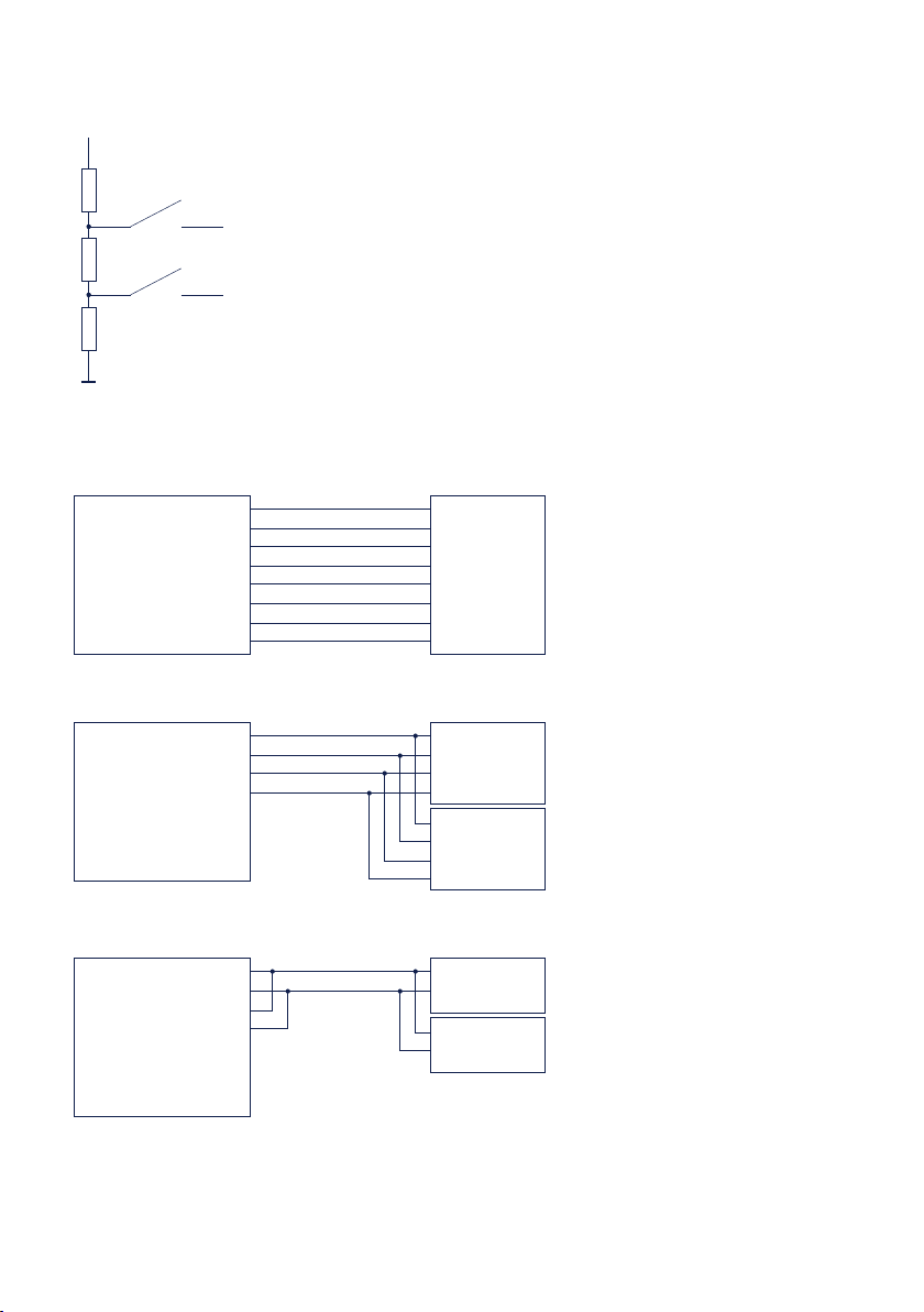
phases of bus operation. Connection of the bus system with
a termination network can be done in the interface by closing
the DIP switches 6 and 7 on the module:
39
Page 40
W&T The serial combi-port
+5V
SW6
SW7
330O 330O120O
Data In B
Data In A
Wiring examples
RS422 connection with hardware handshake
Data Out A
Data Out B
Handshake Out A
Handshake Out B
Com-Server
RS422/485
Handshake In A
Handshake In B
Data In A
Data In B
1
6
2
7
3
8
4
9
RxD A (-)
RxD B (+)
TxD A (-)
TxD B (+)
CTS A (-)
CTS B (+)
RTS A (-)
RTS B (+)
RS485 connection (4-wire bus master)
Data Out A
Data Out B
Handshake Out A
Handshake Out B
Com-Server
RS422/485
Handshake In A
Handshake In B
Data In A
Data In B
1
6
2
7
3
8
4
9
RxD A (-)
RxD B (+)
TxD A (-)
TxD B (+)
RxD A (-)
RxD B (+)
TxD A (-)
TxD B (+)
device
RS585
device
RS585
device
RS585
RS485 connection 2-wire
1
6
2
7
3
8
4
9
Bus A (-)
Bus B (+)
Bus A (-)
Bus B (+)
device
RS585
device
RS585
Com-Server
40
Data Out A
Data Out B
Data In A
Data In B
Handshake Out A
Handshake Out B
RS422/485
Handshake In A
Handshake In B
Page 41

W&T
Subject to error and alteration
6 LED displays
. Power, Status , Error LED
. Network LEDs
41
Page 42
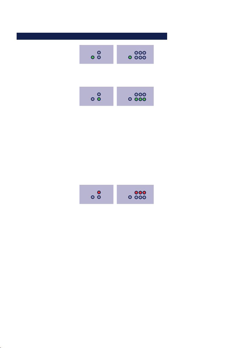
W&T LED displays
6�1 LED displays
Power Status
Status
Power Status
Status
Power Status
Status
Error
Power
ABC
Error
Power-LED
On indicates that power is present on the external screw
terminals or – with model 58665 – via PoE.
Error
Power
ABC
Error
Status-LED
Rapid continuous flashing = bootup, no IP
Rapid continuous flashing (approx. 3x/s) indicates that
the Com-Server is in the bootup phase and/or has not yet
been assigned an IP address. Please use WuTility for example to assign the Com-Server an IP address.
Slow continuous flashing = connection
Periodic flashing (1/s) indicates that the port has a valid
connection to another network station. The status of the
serial port can also be read out using WBM or the ComServer‘s Telnet configuration tool.
Error
Power
ABC
Error
Error-LED
The Error LED uses various flashing patterns to indicate
error conditions on the device or serial port. The error
texts for the previous five serial faults and the associated
system time (time between the last restart of the ComServer and when the error occured) can also be read out
using the Telnet configuration tool.
Rapid continuous flashing = IP address conflict
The IP Address Conflict Detect function is activated and
the Com-Server has detected an IP address conflict. This
means the current IP address of the Com-Server is also
used by other stations in the network. To prevent further
problems, please contact the responsible network administrator and have the conflict resolved.
42
Page 43

W&T LED displays
Subject to error and alteration
2 x flashing = Check serial data format
The serial port received at least one character with a parity
or framing error (= parity error / framing error), or the
data register of the serial receiver ship was written even
though the previous character was not read out. Check the
correctness of the serial parameters, the handshake procedure and the connection cable.
3 x flashing = Check serial handshake
The serial connected device is not responding to the handshake stop signal set by the Com-Server and continues to
send data. The result can be that the serial ring memory
is overwritten and data are lost. Check the handshake
configuration of the device as well as the wiring of the
connection cable.
All LEDs on = Self-test error
The self-test performed after each start or reset of the
Com-Server could not be correctly finished. This error can
occur when you have prematurely broken off a software
update and the full operating software could not be transferred. The Com-Server is no longer capable of being operated in this condition. Repeat the software update over
the network (see Firmware update of the Com-Server), and
address the Com-Server using its assigned IP address.
If the fault cannot be remedied, the problem may lie with
the hardware.
Speed
OFF: Simultaneous illumination/flashing of the Link/Activity LED means there is a link to a device at a rate of 10
MBit/s (10BaseT).
ON: Simultaneous illumination/flashing of the Link/Activity LED means there is a link to a device at a rate of 100
MBit/s (100BaseT)
Speed
Link/Activity
43
Page 44

W&T LED displays
Link/Activity
Speed
Link/Activity
OFF: The Com-Server is not detecting a Link pulse from a
hub or switch. Check the cable or the hub port.
ON: The Com-Server has a valid link to a hub or switch.
The Speed LED indicates the data rate in this case.
Flashing: The Com-Server is receiving or sending network
packets
44
Page 45

W&T
Subject to error and alteration
7 Configuration access to the Com-Server
After completing the hardware installation and assigning the IP address,
the remaining Com-Server configuration takes place over the network.
Here either a Telnet client or, after it has been activated, an Internet brow-
ser can be used.
. Telnet configuration under Windows
. Configuration with the Internet browser
45
Page 46

W&T Configuration access to the Com-Server
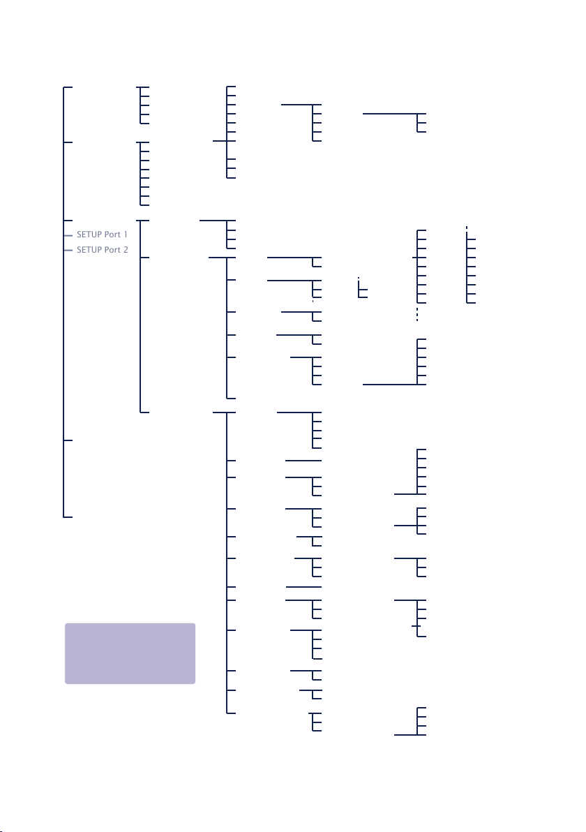
7�1 Configuration menu structure
The setup of the Com-Server is treelike regardless of whether
the configuration is used for a Telnet client or an Internet
browser. An overview of all the levels can be found in the following illustration.
Prior to configuration a valid IP address must have been
already assigned to the Com-Server (see “Assigning the IP
Address”). Access is then possible from virtually any computer
having network access and an installed TCP/IP protocol.
A detailed description of both configuration access types,
their conditions as well as the respective navigation within the
menu tree can be found in the following section.
HTTP protocol and its standard port 80 are fre
1
quent targets of Web attacks. In order not to impair
data throughput of the applications and of the Com-Server,
Web Based Management is therefore factory disabled. Ways of
activating this as part of the startup process can be found in
the section on Web Based Management.
i
If you exit the configuration menu by closing
the Telnet connection
without first invoking
SAVE Setup, the original configuration is
retained.
46
Page 47
W&T Configuration access to the Com-Server
Subject to error and alteration
SETUP Port 1
SETUP Port 2
INFO System Cable Type
SETUP System Setup TCP/IP
SETUP Port 0 Port State Connection State
SAVE Setup
Logout
To activate the new settings
always save using SAVE Setup
with Telnet or the LOGOUT
link on the webpages
(1) Factory defaults are printed bold
MAC address
SOFTW Date/REV
HARDW Rev
Run Time
System Password
System Name
Logfile
Flash Update
Factory Defaults
Reset
Link Speed (Auto, 10|100BT, HD|FD)
UART Setup
TCP/IP Mode
Telnet:
Transfer the selected parameters
and save all settings
in non-volatile memory on the ComServer
Browser:
Transfer the selected parameters
and save all settings
in non-volatile memory on the ComServer
IP-Address (0.0.0.0)
Subnet Mask
Gateway
DNS-Server
MTU (560-1460)
DHCP Client
System Port List
Wake on LAN
Keep Alive Time 30s
Retransm. Timeouts
IP Address Conflict Detect
Byte Counter
Error State
Clear Port Mode
Baud
Parity NONE
Data Bits
Stopbit
Handshake
Receive Buffer (InQueue): 32-4094 Bytes
Port List
TCP Server Activ. Packet Options
TCP Client
UDP Client
Telnet Server Activate yes/no
Telnet Client
FTP Server Activate yes/no
FTP Client
Box to Box
(TCP)
SLIP Router
InQueue Copy
System Options
(1)
Standard Gateway (0.0.0.0)
Route 1
Route 2
Route 3
Route 4
Standard Baudrates
Special Baud Divisor
EVEN
ODD
8
7
1
2
None
Hardware
Software
Special
Local Port TCP/UDP
Controlport TCP
Telnet Port (TCP)
FTP Port (TCP)
Reset Port (TCP)
Server Port
Server IP/URL
Special Options
Server Port
Server IP/URL
Special Options
Telnet Echo
Server Port
Server IP/URL
Special Options
Server Port
Server IP/URL
Special Options
Server Port
Server IP
TLS(SSL) Encryption
Activ. Packet Options
Net Address
SLIP-Net Routing
Local Copy Port
Accepted Copy-Slave IPs
Network Delay
Flush Buffer
Packet Options
SPACE
MARK
Destination
Netmask
Gateway
230,4k
153,6k
115,2k
57600
38400
19200
9600
4800
Pin: RTS
Pin: DTR
Pin: CTS
Pin: DSR
XON/XOFF
XON/XOFF (Filter)
Activ. Packet Options
Inactivity Timeout
Connect. Timeout
Disconnect Char
Client: "C"+Addr
Response Mode
Activ. Packet Options
Client: "C"+Addr
Write: "C"+Addr
Disconnect Char
Disconnect Char
Inactivity Timeout
Serial 0d -> 0d00
Auto FTP
FTP Client Login
Inactivity Timeout
Connect. Timeout
Protocol Char
Start-/Endsequ.
Startsequ. + Length Filed
Interpacket Delay
Fixed Packet Length
2400
1200
600
300
150
110
757200
50
47
Page 48

W&T Configuration access to the Com-Server
7�2 Configuration via Telnet
On Unix/Linux systems as well as Windows up to XP the telnet
client is included in the standard installation of the operating
systems.
The TCP port number for the telnet configuration is configurable in menu path Setup Port x r TCP/IP Mode r Port List r
Telnet Configuration Port. The factory default port number is
1111, so that you must start the connection from within the
telnet client using the corresponding parameter:
telnet [IP-Adresse] 1111
With Windows Vista the telnet client must be explicitly installed together or after the fact. Here we recommend starting
using the WuTility inventorying and management tool. If the
telnet client is not installed on the respective system, an alternate telnet client (putty.exe) is automatically used.
If the connection could be opened and no system password is
assigned (= factory default setting), you will see the following
menu in your Telnet window. If a system password was configured, this will be asked for in front of the menu.
***************************************
* Com-Server [model name] *
* “COMSERVER-0A1B2C” *
***************************************
1. INFO System
2. SETUP System
3. SETUP Port 0 (Serial)
4. SAVE Setup
7�2�1 Navigation within the Telnet menu
An overview of the entire Com-Server configuration menu
is shown on the previous page. On the monitor you will see
48
Page 49

W&T Configuration access to the Com-Server
Subject to error and alteration
always just one level of the selected menu. Simply entering
the number of the desired menu and pressing the ENTER key
takes you to the next level. Entering a q or pressing the EN-
TER key takes you back to the previous menu level.
The last configured value of a menu item appears in parentheses. If you make changes, the new value will appear at
this point the next time the menu is opened. It only becomes
effective in the Com-Server itself however if you have saved it
using SAVE Setup.
As long as you do not open this menu item, you can move
around in the entire menu and change values without actually
changing anything.
Positioning functions for the cursor (arrow keys) or
1
correction actions (backspace, insert) are not available
within the telnet configuration and, if used, will result in faulty inputs. If you make a typing mistake, exit the menu item
using <Enter> and then repeat the entire entry.
49
Page 50

W&T Configuration access to the Com-Server
7�3 Configuration via Browser - Web Based Management
The Com-Server also allows configuration via HTTP protocol
and a standard Internet browser. The menu structure of the
WBM (Web Based Management) is compatible with the Telnet
configuration.
7�3�1 Activating WBM with the WuTility-Tool
The Web-Based-Management of the Com-Server can be activated at any time using WuTility as part of assigning the
network parameters. Select the Com-Server in the device list
and then click on the IP address button. In the first window
of the dialog enter the desired values for IP address, subnet
mask and gateway and then click on the Continue button. In
the following window activate the WBM option and enter the
desired TCP port number. As a rule HTTP standard port 80
should be used. If use of port 80 is not possible or desired,
then the deviating port number must be explicitly specified in
the address line of the browser when opening the Com-Server
homepage:
http://[IP-Adresse oder Hostname]:[Portnummer]
7�3�2 Activating WBM via the serial interface
When serially assigning the IP number, you can optionally
specify the TCP port number under which the WBM should be
accessible. To do this, first connect the serial port A on the
Com-Server and the COM port on your computer using a null
modem cable. Start a terminal program and set the transmission parameters to 9600 baud, 8 data bits, no parity and no
handshake. During a reset of the Com-Server hold the x key
down until after approx. 2 sec. the IPno.+<Enter>: prompt appears. Now directly following the IP address enter the extended address string +w[Portno.]. Portno. represents here the
desired TCP port in decimal format. A value of 0 deactivates
the WBM.
50
Page 51

W&T Configuration access to the Com-Server
Subject to error and alteration
After finishing your entry by pressing the Return key, the
values are stored in the non-volatile memory and you can immediately access the Com-Server and the set WBM port using
your Internet browser.
Additional information about serial configuration
1
possibilities for the Com-Server can be found in the sections Assigning the IP Address.
Example 1:
Here the IP address 172.17.231.99 is assigned to the ComServer and +w80 is used to activate the WBM on the HTTP
standard port.
xxx... -> Com-Server
IP no.+<ENTER>: <- Com-Server
172.17.231.99+w80 -> Com-Server
172.17.231.99 -1 <- Com-Server
Example 2:
In this example the Com-Server gets an IP address, subnet
mask and gateway. In addition +w8585 is entered to activate
WBM on TCP port 8585.
xxx... -> Com-Server
IP no.+<ENTER>: <- Com-Server
172.17.231.99,255.255.0.0,172.17.231.1+w8585 -> Com-Server
172.17.231.99 ,255.255.0.0,172.17.231.1+w8585 <- Com-Server
7�3�3 Activating WBM from the configuration menu
If you want to activate WBM on an already operational ComServer, you can do this via Telnet configuration. Start a Telnet
session on port 1111 of the Com-Server. In the menu branch
SETUP System r Setup TCP/IP r System Port List r WBM Port
enter the decimal number of the desired TCP port under
which you want to reach the WBM. Then press the Return key
until you are back in the main menu and from there open the
51
Page 52
W&T Configuration access to the Com-Server
SAVE Setup item. After you have quit the Telnet session, you
can now access the Com-Server using an Internet browser.
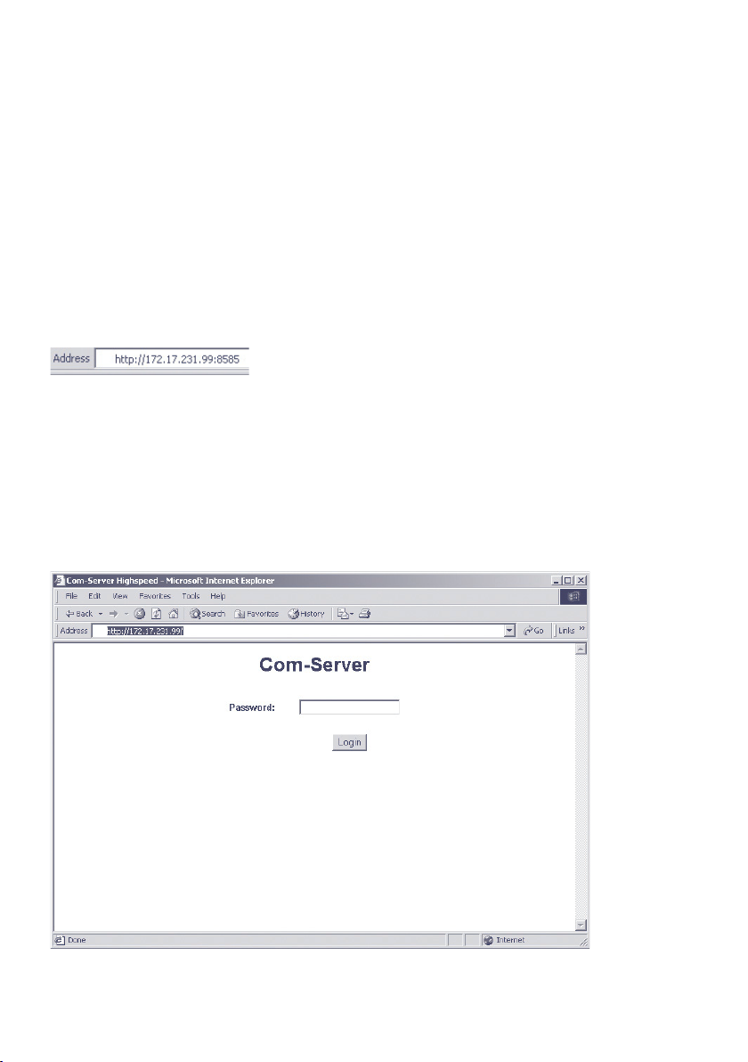
7�3�4 Starting and navigating the WBM
To access the Web pages after activating the WBM, start your
Internet browser and enter the IP address of the Com-Server
and the configured port number in the address line:
http://[IP-Adresse]:[Portnummer]
If the HTTP standard port 80 was configured for WBM, you do
not need to explicitly indicate the port number in the address
line.
You will now be given the start page of the Com-Server with
the system password prompt. The factory default setting is
no system password, so that you can get to the configuration
menu by simply actuating the login button.
52
Page 53
W&T Configuration access to the Com-Server
Subject to error and alteration
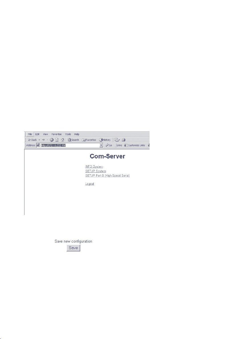
Navigation
Since the WBM of the Com-Server is session-oriented, you
must use backlinks and corresponding control buttons to
navigate to the individual Web pages. Using the Back function
in the browser can lead to problems in accepting the set parameters.
You can make as many settings as desired during a configuration session. Pressing the Send button in the respective pages
pastes them to a clipboard. Once all the settings have been
made, always exit the configuration session using Link Logout
and the Save button there. Only then are the settings you
made copied into the non-volatile memory of the Com-Server
and activated.
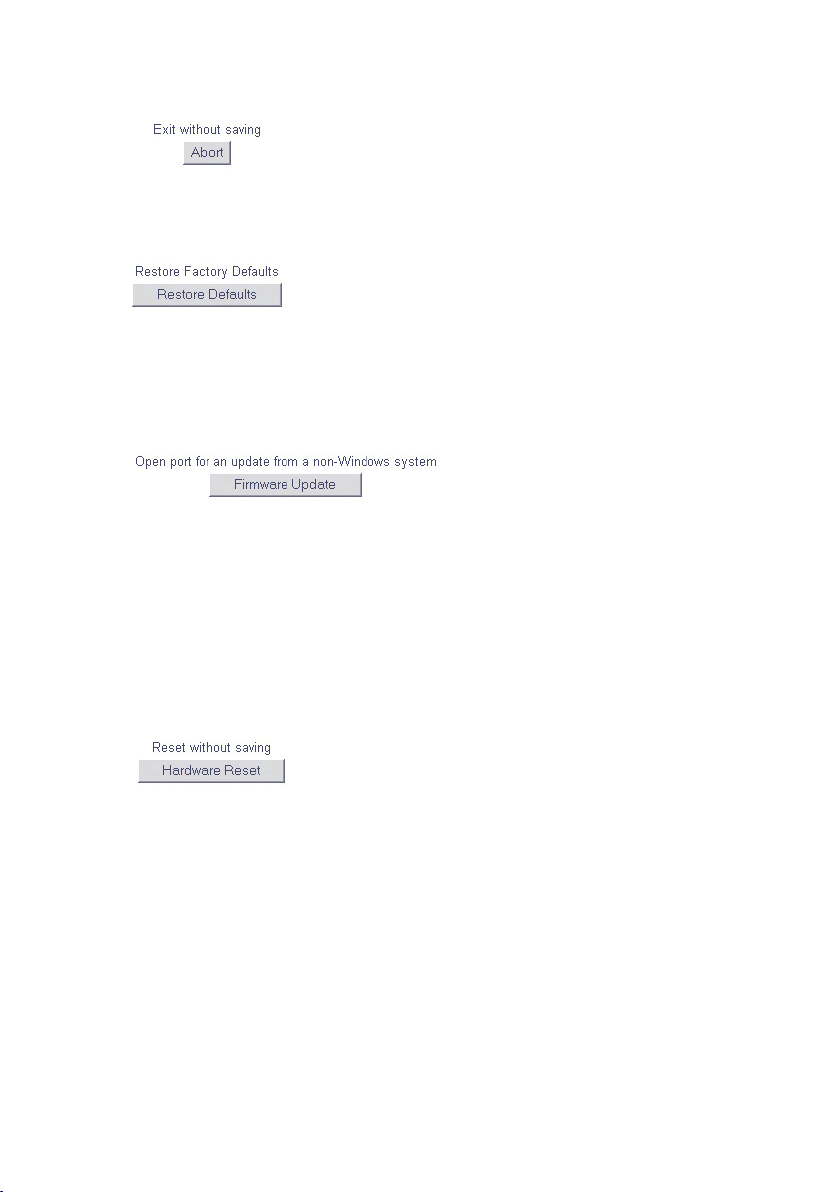
The logout page then offers the following possibilities for
ending the configuration session:
n
Save button causes the Com-Server to save all the changes
you made in its non-volatile memory and quits the configuration session.
53
Page 54
W&T Configuration access to the Com-Server
n
The Abort button causes the Com-Server to reject all the
settings you made and quits the configuration session.
n
The Restore Defaults button resets the Com-Server to its
original factory setting. All settings including the network
parameters IP address, subnet mask and gateway address
are lost.
n
The Firmware Update button activates the mode in which
the Com-Server expects a firmware update via TFTP protocol (see section Firmware Update of the Com-Server).
Update mode can be exited only by complete transmission
of a valid firmware or by interrupting the supply voltage.
When using the WuTility tool for the firmware update, this
mode is automatically started. In this case a manual start
is not necessary.
n
Restarts the Com-Server, comparable with interrupting the
supply voltage. Data from any other opened connections
to the Com-Server are lost in this event.
The functions located on the logout page of the
1
Com-Server can also be found in the Telnet menu branch
SETUP System r Setup TCP/IP.
54
Page 55

W&T
Subject to error and alteration
8 The basis configuration of the Com-Server
Here follows the explanation of all the configuration possibilities related to
the Com-Server operating system and which are not directly related to the
serial ports.
. Save settings
. Menu: INFO System
. Menu: SETUP System
55
Page 56

W&T The basis configuration of the Com-Server
8�1 Save your settings
When configuring using either Telnet or Web Based Management, all the changes are first saved only temporarily in the
Com-Server. To make sure the settings remain intact even
after a reset or power failure, each configuration session must
be ended with an explicit save procedure.
Telnet
From the main menu select SAVE Setup. Respond with y to
the Save Changes ? prompt. If a correct entry was made, the
text Saving… will appear on the monitor, and the Com-Server
saves all the settings you made in its non-volatile memory.
Once the data have been saved, they are activated each time
the Com-Server is turned on or reset.
Entering anything other than y or simply pressing the ENTER
key returns you to the main menu without saving the values.
Exceptions are the network parameters IP address,
1
subnet mask and gateway, since these are also relevant
for the running configuration session. To save and activate
these you must enter q to quit the Telnet configuration after
executing SAVE Setup. The Com-Server then autonomously
performs a reset and only then begins to work with the new
settings.
Browser
Exit the configuration session using the Link Logout and click
on the Save button.
56
Page 57

W&T The basis configuration of the Com-Server
Subject to error and alteration
8�2 Menu: INFO System
This menu allows you to call up device-specific parameters
such as the version njmber and creation date of the firmware,
MAC address of the unit, etc.
Cable type
n
Indicates whether the connection to the hub/switch is
using 10BaseT or 100BaseTX. The duplex procedure is
also indicated (Full- or Half-Duplex).
MAC address
n
Shows the Ethernet address of the Com-Server. This number is factory set and registered. It cannot be changed.
SOFTW Date/Rev�
n
Shows the creation date and version number of the operating software in flash.
HARDW Rev�
n
Shows the version status of the Com-Server hardware.
Run Time
n
Shows the time in hours and minutes since the last ComServer restart.
57
Page 58

W&T The basis configuration of the Com-Server
8�3 Menu: SETUP System
This menu is for configuring all the parameters that pertain to
the Com-Server operating system and are independent of the
serial interface.
8�3�1 Menu: SETUP System r Setup TCP/IP
IP-Address (Default= 0.0.0.0)
n
Enter here the IP address if you want to change it. Please
note that this number is not freely selectable, but rather
needs to be specified based on the network address of the
TCP/IP network. The format corresponds to the normal
syntax (e.g. 172.16.231.5).
Subnet Mask (Default = 255.0.0.0)
n
Enter the subnet mask of the subnet in which the ComServer is located (e.g. 255.255.255.0).
Gateways (Default = 0.0.0.0)
n
In this menu branch the IP address of the standard gateway or router can be configured. If you have not configured fixed routes, the standard gateway is used for all
network packets whose destination IP address is not in the
local subnet.
Route 1 - 4 (Destination, Netmask, Gateway)
n
In addition to the standard gateway, up to four fixed routes can be defined. Packets whose destination addresses
are in the networks configured here (=destination) are
always sent through the gateway assigned to this route. A
fixed route is only accepted and stored by the Com-Server
if the following check is true:
Destination AND Netmask == Destination
Changes to the system parameters IP address,
1
Subnet Mask, Gateway and Route 1-4 cannot be activated right after saving. The Com-Server will use these values
58
Page 59

W&T The basis configuration of the Com-Server
Subject to error and alteration
only after closing the current Telnet connection using q.
DNS Server (Default: 0.0.0.0)
n
The entry contains the IP address of the DNS server (Domain Name System). The latter is needed in all client modes of the Com-Server (TCP, UDP, Telnet, FTP client) if the
destination system is to be stored in the configuration not
as a numerical IP address, but rather in the form of a host
name or URL. The name is resolved by the Com-Server is
done via UDP using standard port 53 reserved for the DNS.
The Time-To-Live of the IP address resolved for a host
name is determined by the Time-To-Live parameter contained in the response from the DNS server. After the name
has been successfully resolved this time is displayed in the
menu item Setup Port x r Port State r Connection State.
MTU – Maximum Transfer Unit (Default: 560)
n
This value determines the maximum size of a TCP/IP pakket. It refers to the number of bytes (excluding header)
that can be sent in a packet. The smaller the MTU, the
more network buffer overall is available in the Com-Server.
The selectable range begins at 560 and ends at 1024
bytes. The values can be set in increments of 128 bytes
(automatic correction).
DHCP Client (Default: 1 = ON)
n
The DHCP protocol is activated with the factory settings
(menu entry = 1). The Com-Server attempts to find a DHCP
server and get an IP address from it. Entering 0 deactivates DHCP and the Com-Server works statically with the IP
address assigned to it. More information on how DHCP
works can be found in the section IP Assignment via DHCP
Protocol.
To prevent unintended address assignments or
1
changes, we recommend deactivating the DHCP protocol if it is not expressly used in the respective network
environment.
59
Page 60

W&T The basis configuration of the Com-Server
n System Port List
From the respective submenus you can configure and
disable the TCP and UDP port numbers under which the
following configuration and control accesses for the ComServer are reached. Entries are made in decimal. The value
0 disables the service.
The TCP/UDP ports with access to the serial port on the
Com-Server can be configured from the submenu Setup
Port x r TCP/IP Mode r Port List konfiguriert werden.
• WBM Port (Default = TCP/0)
Chapter Configuration via Browser
• Telnet Configuration Port (Default = TCP/1111)
Chapter Configuration via Telnet
• SNMP (Default = UDP/161)
Chapter SNMP management
• Device Reset Port (Default = TCP/8888)
Chapter Reset of the Com-Server
• Init Flash Update Port (Default = TCP/8002)
Chapter Firmware update of the Com-Server
• Read Config Port (Default = TCP/8003)
Chapter Up-/Download configuration data
• Write Config Port (Default = TCP/8004)
Chapter Up-/Download configuration data
• Info Port (Default = UDP/8513)
Chapter Inventory via UDP
Changes to the factory default port numbers as
1
well as disabling services should be done with caution, since they can result in malfunction of configuration
and management tools such as WuTility. If for example the
telnet configuration and WBM are disabled, you can no longer configure the Com-Server. Restore the factory default
values by performing a hardware reset of the Com-Server.
60
Page 61

W&T The basis configuration of the Com-Server
Subject to error and alteration
n Wake on LAN (Default: deactive)
Up to three Ethernet addresses for network components
can be configured, which are enabled when there is a restart of the Com-Server via Wake-on-LAN.
For proper function of Wake-on-LAN it must be
1
supported and activated by the BIOS and the net-
work card in the destination computer.
Keep Alive Time (sec) (Default: 30s)
n
If the keep-alive check is activated by entering and saving
a value in second ticks, all TCP connections are monitored
for network-side data traffic. If there is no network traffic
within the set time, the Com-Server generates a keep-alive
packet. If the partner does not answer this packet, the
connection is reset in the Com-Server. This deletes any
data still contained in the serial in- and output buffers.
Example: A TCP client has opened a connection to TCP
server port 8000 of the Com-Server and the network connection is interrupted. After the set keep-alive time plus 2s
for two repetitions has elapsed, the Com-Server closes the
connection and is again ready for any other clients.
Retransmission Timeouts (ms) (Default: 240)
n
This timeout determines what time must elapse before
network packets are repeated if necessary. In most networks the default setting of 240ms can be used. Only
when there are very long latency times between the
Com-Server and its respective communications partner
would you need to increase this value.
IP Address Conflict Detect (Default: deactive)
n
Firmware version 1.31 and higher enables the Com-Server to detect and display an IP address conflict. An active
check is performed each time the Com-Server is restarted. Only passive monitoring is performed during normal
61
Page 62

W&T The basis configuration of the Com-Server
running. Details on this functionality can be found in
RFC5227, IPv4 Address Conflict Detection.
If the Com-Server detects that its current IP address is also
being used by another station in the local network, it indicates this conflict by rapid flashing of the Error LED. In addition a corresponding message including the competing
MAC address is generated in the Error State (Setup Port x
r Port State r Error State).
When using a static IP address the conflict is only indicated. The Com-Server continues to use this IP address. In a
DHCP environment the Com-Server informs the responsible DHCP server, resets the IP address and waits for assignment of a corrected IP address.
IP address conflicts generally lead to communication
1
problems which are difficult to diagnose. Please therefore inform the responsible administrator in such cases.
8�3�2 Menu: SETUP System r System Password
The system password, which consists of any 31 (max.) characters, protects against any subsequent configuration and
control access to the Com-Server.
· Telnet configuration menu (Default = 1111/TCP)
· WBM (if enabled)
· Init Flash Update Port (Default = 8002/TCP)
· Read the configuration file (Default = 8003/TCP)
· Write the configuration file (Default = 8004/TCP)
· Reset Com-Server (Default = 8888/TCP)
· Reset Port Status (Default = 9084/TCP)
· Controlport (Default = 9094/TCP)
· SNMP (Default = 161/UDP)
On Telnet port 1111 and on WBM port the system password is
prompted as soon as the connection is opened. For all other
62
Page 63

W&T The basis configuration of the Com-Server
Subject to error and alteration
associated TCP ports the password must be null-terminated
(=[password] + 0x00) and sent to the Com-Server no later
than 2s after the TCP connection has been established. Queries from SNMP managers are only responded to by the ComServer if the community corresponds to the system password.
For additional information on using system passwords in
conjunction with the configuration and control ports, see the
section Expanded Services of the Com-Server.
8�3�3 Menu: SETUP System r System Name
The freely configurable system name consisting of max. 31
characters is used to identify the Com-Server. This name is
displayed as an opening message in the client for all Telnet
sessions.
If the tag <wutl> is used inside the system name, the ComServer replaces it each time there is an output or communication with the last three places of its Ethernet address.
8�3�4 Menu: SETUP System r Logfile
The Logfile contains the last (max. 3000) connections and
connection attempts for configuration accesses by the ComServer with the associated time stamp and address parameters.
Accesses to the following services are registered:
· Telnet configuration menu (Default = 1111/TCP)
· WBM (if enabled)
· Init Flash Update Port (Default = 8002/TCP)
63
Page 64

W&T The basis configuration of the Com-Server
· Read the configuration file (Default = 8003/TCP)
· Write the configuration file (Default = 8004/TCP)
· Reset Com-Server (Default = 8888/TCP)
· Reset Port Status (Default = 9084/TCP)
Activate Logfile (Default= 0 = OFF)
n
A 1 activates recording. In addition the Save Interval must
be configured to a valid value.
Save Interval (min) (Default= 0)
n
Configuration of the time interval in minutes at which the
Logfile is written to the non-volatile memory of the ComServer.
Saving the Logfile has an influence on the
1
latencies of the serial data transmission. We recommending configuring the Save Interval only as low as
absolutely necessary. When timeouts occur in serial data
exchange, logging should be disabled on a test basis.
Delete Logfile
n
Deletes the entire Logfile including the non-volatile stored
entries.
Reading/Viewing the Logfile
The Logfile can be viewed using the Web Based Management
of the Com-Server under Setup System r Logfile r Load. The
Logfile can be downloaded via TFTP. The name to be specified
in the TFTP client must be wut_cs_logfile. (Note period at the
end!)
64
Page 65

W&T The basis configuration of the Com-Server
Subject to error and alteration
8�3�5 Menu: SETUP System r Flash Update
Before you activate the update mode, make sure that you have
quit any active network connections. Then confirm with „y“.
The update mode is indicated by lighting of the Status LED on
the Com-Server.
WuTility automatically enables update mode through TCP port
8002. Manual enabling is therefore only necessary if this port
is blocked, such as by a firewall.
You may quit the update mode only by either
1
completely performing the update or by means of a reset, i.e. turning off the power!.
8�3�6 Menu: SETUP System r Factory Defaults
Enter a y to restore the factory default settings.
Resetting the non-volatile memory causes loss of all
1
the settings which deviate from the default values, including the IP address.
8�3�7 Menu: SETUP System r Reset
Select this menu item to perform a software reset on the
Com-Server. First your Telnet connection is properly closed.
All data from any still open network connections are
1
lost.
8�3�8 Menü: SETUP System r Link Speed
The Com-Server is factory set for autonegotiation. Data transmission speed and duplex procedure are automatically negotiated with the connected switch/hub and set correspondingly.
65
Page 66

W&T The basis configuration of the Com-Server
In addition to autonegotiation, the Com-Servers as well as
many manageable switches can be configured for fixed
transmission parameters with respect to speed and duplex
procedure. To prevent communications problems (duplex mismatch), only the following two combinations are permitted:
• Both parties (switch and Com-Server) are operated in Auto-
Negotiation mode (recommended).
• Both parties are configured for the same (fixed) transmissi-
on speeds and duplex mode.
Changing the link speed is activated only after
1
saving and exiting the telnet or WBM session by means
of an automatic Com-Server reset. Data from any open network connections is lost. If the newly selected setting is not
supported by the port used on the switch ort hub, the ComServer may then not be accessible.
66
Page 67

W&T The basis configuration of the Com-Server
Subject to error and alteration
8�4 Menu ��� r TCP/IP Mode r System Options
n Network Delay [10ms-Ticks]
Default: 0000)
This value specifies the minimum delay time of the ComServer after serial data have arrived. After this time has
expired, it packs the data into a network packet and sends
them to the respective communications partner. The default setting 0 means the attempt is made to send the data
as quickly as possible. The resulting high time transparency does however bring with it the drawback of a higher
number of network packets.
If the serial transmission takes place in predictable block
sizes, this value can be adjusted to optimize the network
load. There is also the advantage that the serial blocks are
transmitted within a network packets, so that they arrive
at the receiver bundled.
Example:
You are using serial data blocks of 25 bytes each and
transmission parameters of 9600 baud, 8 data bits, no parity and 1 stop bit. Each block thus has a length of approx.
26ms (1/9600 * 10 bits * 25 bytes). If the network delay is
set here to a value of 3 (=30ms), each block is sent to the
receiver with a network packet.
The situation described here applies only to a non
1
overloaded and error-free network. If there are interruptions in the data flow on the network side, any serially
accumulated data are also sent in larger network packets.
For secure closed transmission of serial datagrams in a
network packet we recommend the use of Packet Options.
For details, see the section on Packetizing serial data-
grams.
67
Page 68

W&T The basis configuration of the Com-Server
n Flush Buffer
Default: active
If this switch is active, the serial buffer is cleared each
time a new connection is opened; any residual data which
cannot be transmitted (e.g. handshake stop of the serial
terminal device) are thus lost. But if you connect a terminal device to the Com-Server which for example requires a
longer handshake stop for program reasons, you can prevent clearing of the buffer by deactivating the switch. In
this way multiple connections can be opened one after the
other on the network side and the data are accumulated in
the buffer until they are sent.
Packet Options
n
Default: deactive
The Packet Options in this menu branch are criteria which
allow the Com-Server to detect the start and end of contiguous datagrams in serial receiving. They allow a serial
datagram to be sent to the communication partner closed
in a network packet. In addition to start/end sequences
and fixed packet lengths, pauses can also be triggered in
the data stream.
For details, see the section on Packetizing serial data-
grams.
68
Page 69

W&T
Subject to error and alteration
9 Configuration of the serial port
. Configuring the serial transmission parameters
In addition to the usual settings for baud rate, data bits, parity and stop
bits, the various handshake procedures and available special functions of
the individual control signals are explained here.
. Setting the TCP/UDP services with access to the serial port
69
Page 70

W&T Configuration of the serial port
9�1 The serial parameters (Menu: UART Setup)
All RS232 parameters relevant to operation are configured in
the submenu Setup Port x r UART Setup. An overview of the
entire configuration tree can be found in the section Structure
of the Configuration Menu.
If you are using the device in conjunction with the W&T COM
Port Redirector, it is not necessary to configure the serial
parameters in the Com-Server. The COM Port Redirector automatically sets the parameters needed by the serial application
in the Com-Server.
The settings only become active after saving with
1
SAVE Setup or pressing Save on the Logout page.
9�1�1 Baud rate, Data bits, Stop bits, Parity
The desired transmission parameters can be selected by entering the corresponding designation in the respective branch
of the menu tree. Invoking Save Setup in the master menu or
Save on the WBM logout page saves the changes you made in
the non-volatile memory of the Com-Server and simultaneously activates them.
Freely selectable baud rate (Special Baud Divisor)
In the submenu Special Baud Divisor you can enter any desired divisor for generating the baud rate. This makes it possible to work even with non-standard baud rates. The baud rate
and divisor are calculated using the following formulas.
Com-Server++, 58665
n
Divisor=
The maximum baud rate of the Com-Server++ is 230,4kBd,
which corresponds to a divisor of 11.
70
32*Baudrate
83*10
6
Baudrate=
32*Divisor
83*10
6
Page 71

W&T Configuration of the serial port
Subject to error and alteration
n Com-Server 3x Isolated
Divisor=
7,3728*10 7,3728*10
64*Baudrate
The maximum baud rate of the Com-Server 3x Isolated is
115,2kBd, which corresponds to a divisor of 1. 230,4kBd is
only available as standard baudrate.
The currently configured baud rate is displayed when selecting the submenu SETUP Port x (serial) r UART Setup.
9�1�2 The handshake modes
(SETUP Port x r UART Setup r Handshake)
This menu provides three standard modes for flow control of
the serial port. As opposed to these predefined handshake
profiles, you can use the Special submenu to specify the function of each control signal individually. Details on the control
line functions are contained in the description of the submenu
Handshakle r Special.
Hardware handshake
n
Flow control is handled using the RTS and CTS signals.
The Com-Server only sends data to the serial device if
the CTS input is High. In the opposite direction the ComServer indicates readiness using the RTS line.
6
Baudrate=
6
64*Divisor
Function control signal: RTS: Flow Control
DTR: Show Connection
CTS: Flow Control
DSR: NO
n Software handshake
The software handshake is implemented using the two
ASCII characters (11H)=XON and (13H)=XOFF. In the standard setting Software Handshake these two codes are considered by the Com-Server as control characters and are
71
Page 72

W&T Configuration of the serial port
filtered out from the actual data flow in both directions.
This filtering can be turned off individually for each data
direction in the Special submenu.
Function control signal: RTS: NO (Default HIGH)
DTR: NO (Default HIGH)
CTS: NO
DSR: NO
n NO handshake
Turns off any hardware or software flow control for the
serial interface. All the data are output to the connected
terminal device regardless of the status of the inputs CTS
and DSR. Any impending overflow of the serial input buffer
is not signalled by the Com-Server. The setting NO Handshake makes sense for any data transmission that uses a
serial protocol for data integrity or flow control.
Function control signal: RTS: NO (Default HIGH)
DTR: NO (Default HIGH)
CTS: NO
DSR: NO
n Special
Here it is possible to configure the function of the control lines differently from the three predefined protocols.
Toggle between on and off by entering the menu number
of the desired function. Settings made here are correspondingly overwritten by selecting one of the three predefined
handshake modes.
Pin: RTS & Pin: DTR
n
The following functions can be assigned to the outputs
RTS and DTR:
1� Flow Control – If this function is turned on, the
Com-Server handles the RS232 flow control through
the corresponding output. The ready state for serial
data is signaled by a HIGH signal (+3...12V). If the memory limit of the input buffer is reached, the line is set
to LOW (-3...-12V).
72
Page 73

W&T Configuration of the serial port
Subject to error and alteration
2� Show Connection – The output is switched to the
serial port depending on an existing TCP connection.
HIGH (+3...12V) indicates an existing connection.
3� NO (Default=HIGH) – The outputs are not used
by the Com-Server and carry a constant HIGH level
(+3...12V).
4� NO (Default=LOW) – The outputs are not used by
the Com-Server and carry a constant LOW level (-3...12V).
PIN: CTS und PIN: DSR
n
The inputs CTS and DSR can be assigned the following
functions:
1� Flow Control – The serial flow control is performed
using the corresponding pin. Serial data are output
only if the input was set to HIGH (+3...12V) by the connected terminal device.
2� OPEN/CLOSE – Connection This option for TCP
connection building and ending can be used to control
connection building and ending in all Com-Server client
operating modes. If the IP address and the TCP port
are stored in the Com-Server, a HIGH level (+3...12V)
on the corresponding input establishes a connection.
The connection is closed with a LOW level (-3...-12V).
3� Accept only by HIGH – Connection establishment of a TCP client is only accepted if a HIGH level
(+3...12V) is present on the corresponding input. Likewise the connection is rejected when there is a LOW
level.
4� NO (Manual IN) – The selected input is ignored by
the Com-Server.
XON/XOFF
n
Here the handshake can be configured for XON/XOFF
separately for each data direction. XON/XOFF Receive
switches processing of this control character for serial receiving on: After receipt of an XOFF sent by the
73
Page 74

W&T Configuration of the serial port
RS232 terminal device, the Com-Server stops serial
data output until it receives an XON. If XON/XOFF Send
is turned on, the Com-Server generates an XOFF when
it is no longer able to receive serial data.
XON/XOFF (Filter)
n
If XON/XOFF is turned off for flow control, this option
can be used to separately determine for both data directions whether the Com-Server filters these control
characters out of the actual data.
1� Send-Filter (Data direction network r serial)
If this option is turned on and XON or XOFF characters
occur in the actuqal data, the Com-Server filters them
out and does not pass them along to the terminal
device. Select this mode generally for bi-directional
RS232 connections, since otherwise you will have
problems with data traffic. If the Send-Filter option
is turnd off, all the data including the XON and XOFF
characters are sent unfiltered on the RS232 interface.
This mode only makes sense if the connected terminal
device is a graphics printer whose data stream can be
expected to contain handshake characters.
2� Receive-Filter (Data direction serial r network)
If this option is turned on, the Com-Server interprets
the XON and XOFF characters sent by the serial terminal device as control bytes and does not insert them
into the network data stream. This ensures that the recipient in the network only gets actual user data. If Receive-Filter is turned off, the XON and XOFF characters
sent by the serial terminal device are transmitted to the
network together with the actual user data. This mode
requires of the respective recipient in the network that
it be able to separate actual data from control data.
The currently selected parameters are shown in the top line of
the UART Setup menu:
74
Page 75

W&T Configuration of the serial port
Subject to error and alteration
[Baud], [Parität], [Datenbits], [Stopbits], [Handshake]
Possible values for the handshake variables are:
Send filter Receive filter
[N] No handshake --- ---
[H] Hardware handshake --- ---
[S] Software handshake
Xon/Xoff
[Special] Special >setting
configuration menu
„Handshake Special“
ON ON
--- ---
9�1�3 Receive Buffer (InQueue)
The Com-Server is factory configured with a serial input buffer
capacity of 4094 bytes. The sub-menu Receive Buffer allows
you to reduce this to 32 bytes, with only even values permitted.
In most applications the emphasis is on maximum data
throughput, so we recommend not changing the maximum
value of 4094. It does however make sense to reduce the
value when working with serial protocols together with unreliable or noisy network connections. This prevents datagram
repetitions from being accumulated on the part of the serial
master when there are connection errors and keeps them
from being sent in bundled form after the connection is resumed.
Please ensure that when communicating without
1
serial flow control the Receive Buffer is at least as large
as required for the longest expected serial data packet.
9�1�4 FIFO Send/Rec (only Com-Server 3x Isolated)
The submenu allows the FIFO memory of the serial receiver
component to be turned on and off. It is recommended that
75
Page 76

W&T Configuration of the serial port
the FIFOs be turned on to reduce the system load especially
when sending large data quantities at high baud rates above
57600. If for example you need a short delay in sending data
as possible when working with serial protocols, the FIFOs
should on the other hand be turned off.
76
Page 77

W&T Configuration of the serial port
Subject to error and alteration
9�2 TCP-/UDP port numbers (Menu: TCP/IP Mode)
In the menu branch Setup Port x r TCP/IP Mode r Port List
you can configure the TCP server ports for all services with
access to the serial ports on the Com-Server. Changes to the
port numbers must be set the same in the client-side communication partner. A value of 0 disables the service.
Changes to the factory-set port numbers as well as
1
disabling services should be done with caution, since
these can result in a connection break to any connected communication partners such as the COM Port Redirector. If the
Local Port is disabled, no data exchange with the serial connected device is possible. The default values can be restored
by resetting the Com-Server to its factory default settings.
Local Port TCP
(Default = 8000/Port A, 8100/Port B, 8200/Port C)
Under this port number a data-transparent TCP connection to
the serial port on the Com-Server is made available. The port
is required for use in the operating modes TCP Server, COM
Port Redirector and Box-to-Box.
For detailed information see chapter:
Data transfer per TCP/IP-Sockets
The Windows COM port redirector
Box-to-Box mode
Controlport
(Default = 9094/Port A, 9194/Port B, 9294/Port C)
The control port allows configuration of the serial port on
the Com-Server over the network. Use of the control port is
required for operation together with the COM Port Redirector.
For detailed information see chapter:
The Windows COM port redirector
The Controlport
77
Page 78

W&T Configuration of the serial port
Telnet Port/TCP
(Default = 6000/Port A, 6100/Port B, 6200/Port C)
The telnet port allows access to the serially connected device
with a standard telnet client. The port is always required for
Telnet Server mode.
For detailed information see chapter:
Telnet Server
FTP Port/TCP
(Default = 7000/Port A, 7100/Port B, 7200/Port C)
The FTP port enables access to the serially connected device
with a standard FTP client. The port is always required for FTP
Server mode.
For detailed information see chapter:
FTP Server
Reset Port Status
(Default = 9084/Port A, 9184/Port B, 9284/Port C)
For special applications this port offers the ability to carry out
a forced reset of the Com-Server port: the parameters for the
current connection are deleted.
For detailed information see chapter:
Reset Com-Server Port
78
Page 79

W&T
Subject to error and alteration
10 Packetizing serial datagrams
Some serial protocols monitor the synchronous reception of datagrams
with character delay time. When this timeout between two characters is ex-
ceeded the associated datagram is rejected or evaluated as a transmission
error. In such environments it may be necessary to send serial datagrams
closed in a packet on the network side as well.
. Packet Options
. Start-/Endsequence, Length Field
. Interpacket Delay
. Fixed Packet Length
79
Page 80

W&T Packetizing serial datagrams
10�1 Packet Options
Packet Options in the menu path Setup Port x r TCP/IP Mode
r SystemOptions are criteria which allow the Com-Server to
detect the start and end of contiguous datagrams in serial
receiving. They allow a serial datagram to be sent to the
communication partner closed in a network packet. Such datagram-optimized transmission is often necessary in tunneling
and transmission of serial protocols which require synchronous reception of the data packets with a defined character
delay time.
For serial protocols which emphasize the greatest possible
latency-free transmission and shortest possible acknowledgement delay time, Packet Options should not be used.
By factory default the Com-Server operates latency-optimized
and sends received data as soon as possible to the respective
communication partner.
Regardless of how Packet Options is configured, the
1
Com-Server sends all received data to the network-side
communication partner as soon as the set MTU is reached.
The factory default setting for this is 560 bytes. In the menu
path Setup System r Setup TCP/IP r MTU this can be increased to max. 1024 bytes.
The set Packet Options apply to the following Com-Server
modes.
• TCP client
• TCP server
• UDP peer
• COM redirector
• Box-to-Box
• OPC server
80
Page 81

W&T Packetizing serial datagrams
Subject to error and alteration
10�1�1 Startsequence/Endsequence
The Com-Server sends the datagram when one of the two
configured Start AND End sequences has been received. If the
network send will be triggered only by an End Sequence, Start
Sequence Size 1 and Start Sequence Size 2 must be configured
to 0.
Activate this Packet Option (Telnet)
n
Activates the selected option for serial data reception.
Start Sequence Size 1/2
n
Enter the length of the respective Start Sequence in bytes.
The max. length is 3. A value of 0 deactivates monitoring
of the Start Sequence.
Start Sequence 1/2
n
Hexadecimal, space-delimited byte sequence of the respective Start Sequence. The input field is only activated if
the sequence size was previously specified and sent to the
Com-Server.
End Sequence Size 1/2
n
Enter the length of the End Sequence in bytes. The max.
Length is 3.
End Sequence 1/2
n
Hexadecimal, space-delimited byte sequence of the respective End Sequence. The input field is only activated if
the sequence size was previously specified and sent to the
Com-Server.
Additional Bytes
n
Number of bytes which follow after the End Sequence 1 or
2 and belonging to the serial datagram (e.g. checksum)
81
Page 82
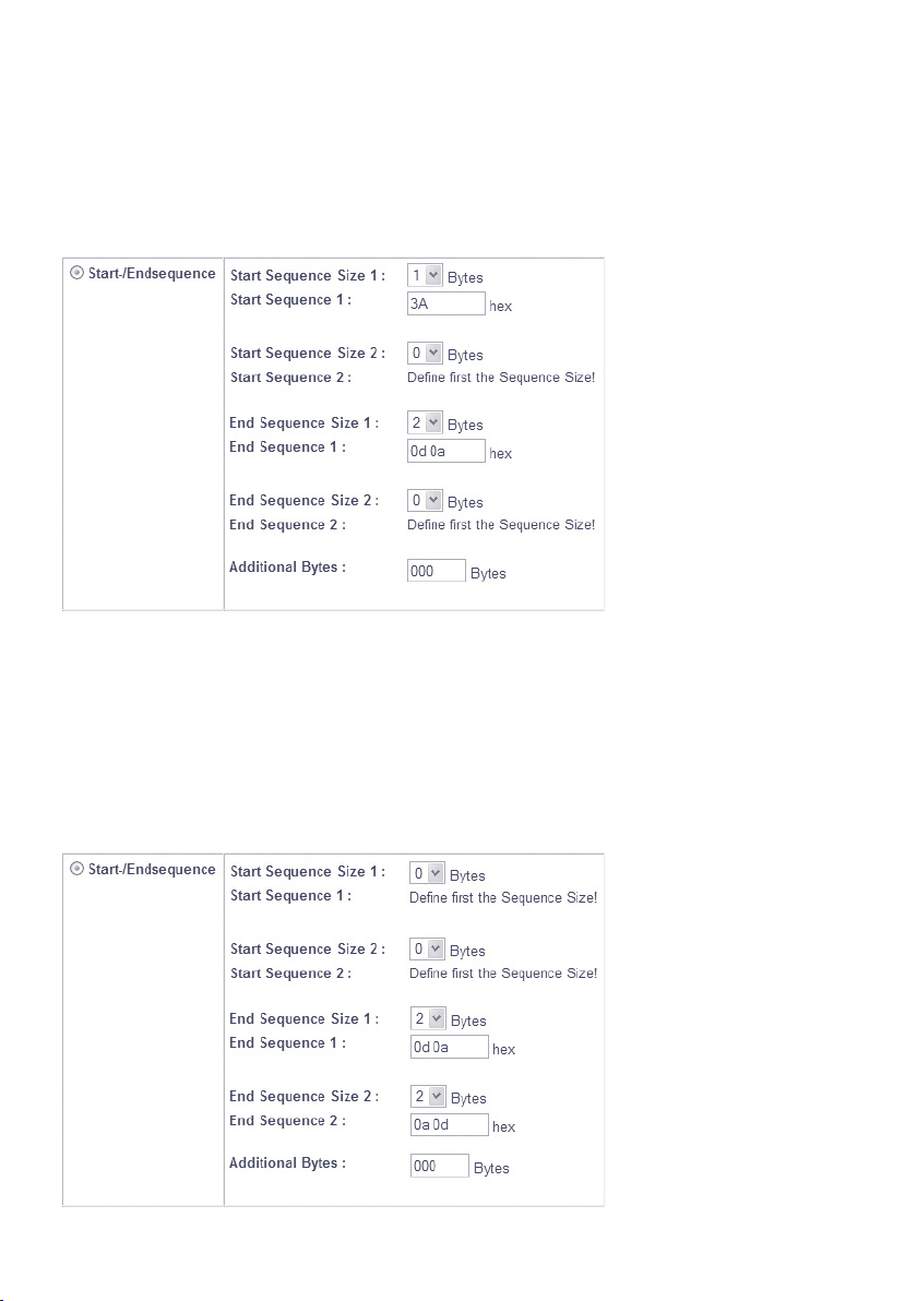
W&T Packetizing serial datagrams
Example 1:
Modbus/ASCII begins each datagram with the character :
(0x3a). The end of the datagram is indicated by the character
string CRLF (0x0d, 0x0a).
As soon as the Com-Server has received the character 0x3a, it
collects more data until the End Sequence 0x0d 0x0a is received and then passes the datagram to the network.
Example 2:
The block end of a serial protocol is indicated by the character strings CRLF or LFCR.
82
Page 83
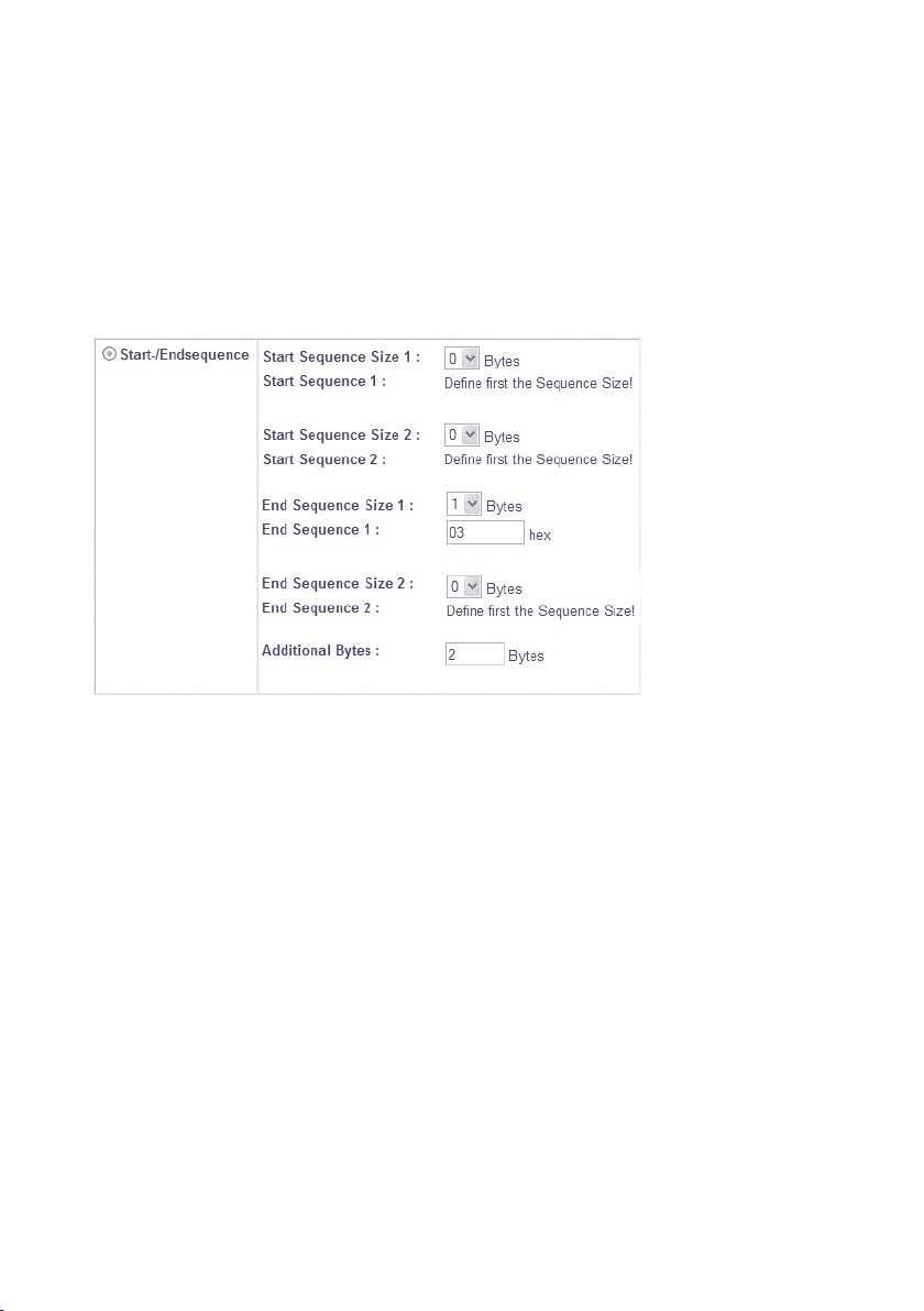
W&T Packetizing serial datagrams
Subject to error and alteration
The Com-Server collects incoming serial data until receipt of
the End Sequence CRLF or LFCR and then passes the datagram
to the network.
Example 3:
The block end of a serial protocol is followed by the character
ETX (0x03) followed by a 16-bit checksum.
The Com-Server collects incoming serial data until receipt of
the character ETX (0x03) plus the next two following bytes
and then passes the datagram to the network.
83
Page 84

W&T Packetizing serial datagrams
10�1�2 Startsequence + Lengthfield
The Com-Server sends the datagram after reception of a Start
Sequence and evaluation of a length specification contained in
the datagram.
Activate this Packet Option (Telnet)
n
Activates the selected option for serial data reception.
Start Sequence Size
n
Enter the length of the Start Sequence in bytes. The max.
Length is 3.
Start Sequence
n
Hexadecimal, space-delimited byte sequence of the respective Start Sequence. The input field is only activated if
the sequence size was previously specified and sent to the
Com-Server.
Length Field Offset
n
Start position of the length field within the serial datagram
in bytes. Counting method beginning with 0.
Size
n
Length of the length field in bytes. In the protocol field defined by Length Field Offset, Size and Byte Order, the ComServer expects specification of the total length of the serial
datagram, including any Start Sequence and appended
checksum. If the length specification is defined differently
within the serial protocol, a corresponding correction may
be needed using the Additional Bytes option.
Clean network-side packetizing is only assured if
1
the serial datagrams do not exceed the MTU of the
Com-Server. The factory default setting for this is 560
bytes. In the menu path Setup System r Setup TCP/IP r
MTU this can be extended to 1024 bytes.
84
Page 85
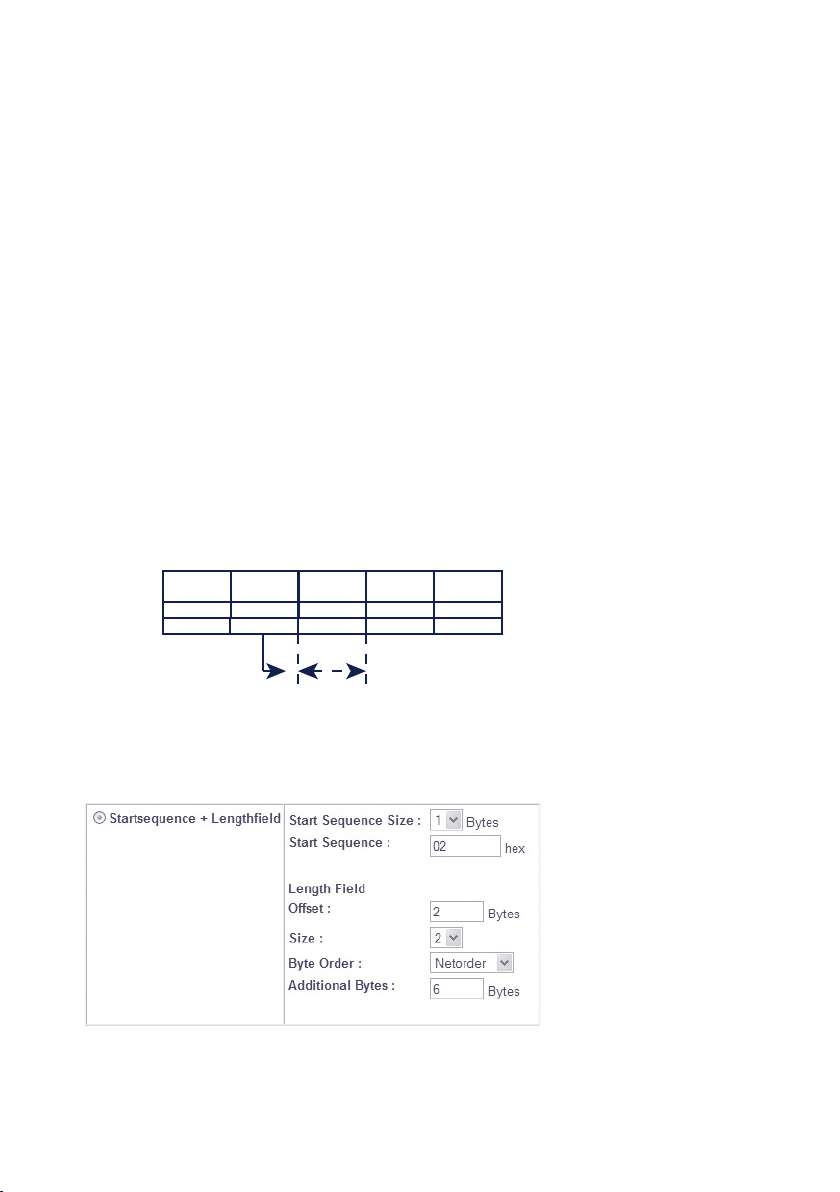
W&T Packetizing serial datagrams
Subject to error and alteration
n Byte Order
Organization of the length field (net order = high-bytefirst; byte order = low-byte-first)
Additional Bytes
n
Any number of bytes which may not be accounted for in
the length specification of the serial protocol (e.g. Start
Sequence, appended checksum, etc.). This means the contents of the field defined by Size may have to be corrected
to the total length of the serial datagram using the Addi-
tional Bytes option.
Example
The serial protocol shown in the following always starts with
the character STX (0x02). In the Length field the length of
the following data field (serial data) is specified without the
checksum and without the previous fields. The Block End is
indicated by a variable 16-bit checksum.
Description
Size [byte]
Value
Start
Sequence
STX (02) any High/Low
Serial
Address
1
Len-Field
(Netorder)
1 2 x 2
=
Serial
Data
CRC16
any
The following settings must be made on the Comt-Server for
correct packeting of this protocol structure:
As soon as the Com-Server has received the character 0x02 it
collects additional data. If the total number of incoming cha-
85
Page 86

W&T Packetizing serial datagrams
racters is equal to the sum from the Length field and Additional Bytes, the datagram is passed to the network.
10�1�3 Interpacket Delay
The Com-Server structures the serial data stream based on a
configurable rest pause in ms for serial reception. This means
after receipt of any character the following data are collected
until no more characters have been received within the time
set as Interpacket Delay. Only now is the datagram passed
into the network.
Activate this Packet Option (Telnet)
n
Activates the selected option for serial data reception.
Interpacket Delay
n
Enter the desired Interpacket Delay in ms. The permissible
minimum value is 3ms. The tolerance is approx. 1 character length, as results from the serial parameters which are
set.
Regardless of the configured Interpacket Delay the
1
Com-Server sends incoming data to the network-side
communication partner only once the set MTU is reached. The
factory default setting for this is 560 bytes. In the menu path
Setup System r Setup TCP/IP r MTU this can be extended to
1024 bytes.
Example
Modbus/RTU separates datagrams using a rest pause of at
least 3.5 character lengths. A baud rate of 9600 with data format 1 start bit + 8 data bits + 1 stop bit results in a character
length of approx. 1ms. For 3.5 character lengths this results a
rounded-off Interpacket Delay of 4ms:
86
Page 87

W&T Packetizing serial datagrams
Subject to error and alteration
10�1�4 Fixed Packet Length
The Com-Server structures datagrams based on a fix number
of characters. This means datagrams are not passed to the
network until the set number of characters has been received.
Activate this Packet Option (Telnet)
n
Activates the selected option for serial data reception.
Fixed Packet Length
n
Enter the desired number of characters.
The value set under Fixed Packet Length is limited to
1
the size of the MTU. The factory default setting for this
is 560 bytes. In the menu path Setup System r Setup TCP/IP
r MTU this can be extended to 1024 bytes.
Example
A serial device always replies to the polling from a master
with a fixed datagram length of 30 bytes.
For correct packeting of this protocol the following settings
must be made on the Com-Server:
87
Page 88

88
W&T Packetizing serial datagrams
Page 89

W&T
Subject to error and alteration
11 Mode TCP-Server
The most direct way to exchange data with a serial device connected to
the Com-Server is via TCP sockets. This is especially useful in cases where
communication needs to be integrated into your own programs. Compa-
rable to traditional telephony, TCP connections always consist of an active,
calling side (=Client) and a passive, call-answering side (=Server). The Com-
Server LC works like a TCP server and enables network clients to access the
serial connected device.
. The Com-Server as TCP-Server
89
Page 90

W&T Mode TCP server
11�1 The Com-Server as TCP server
TCP is a connection-based protocol, i.e. during data transmission there is a fixed connection between client and server.
TCP possesses all the mechanisms for opening and closing
a connection and ensuring errorless data transfer over the
network.
The connection is controlled by the user program (client
process), which opens (connect()) and closes (close()) the
connection. Once a connection is established, data can be
exchanged bidirectionally between the two processes. The
Com-Server output all the data from the LAN to the serial prot
and in return reads in all the data from the serial port in order
to convey it to your client process.
It must be noted that only one TCP client at a time can be
connected to the serial port of the Com-Server. If there is
already a connection, any attempt from another client is rejected until this first connection has been properly closed or
ended by means of a reset.
When there is no connection, the entry FREE must
1
be visible in the Com-Server port menu SETUP Port x r
Port State r Connection State. If a connection is active, the
entry In Use Port number <IP address> appears there.
Application examples TCP-Server mode
• A separate client program should be created for polling
the device serially connected to the Com-Server. TCP sokket communication is supported by all modern programming and script languages.
• The communication program associated with the serial
device offers as a standard feature the ability to specify an
IP address/port number as the destination interface.
90
Page 91

W&T Mode TCP server
Subject to error and alteration
11�1�1 Configuration of the local port number
SETUP Port x
...
TCP/IP Mode
...
Port List
Local Port TCP/UDP
To open a connection to the Com-Server, a client needs an
IP address and the TCP port number. Direct access via TCP
to the serial port of the Com-Server is done using the port
number stored in the menu branch Setup Port x r TCP/IP
Mode r Port List r Local port (TCP). Port number 8000 is preconfigured at the factory
11�1�2 Optional settings
Serial transmission parameters
SETUP Port x
...
UART Setup
Baud, Parity, Data Bits,
Stopbits, Handshake
Baud rate, data bits, parity and handshake procedure must
conform to the connected serial device. For details see section
Configuration of the Serial Port.
Serial receive buffer
SETUP Port x
...
UART Setup
The Com-Server has a variable serial receive buffer of approx.
4kB. The menu item allows this value to be reduced. Whether
the serial receive buffer is automatically cleared when a connection is opened or any existing older data are sent to the
...
Receive Buffer
91
Page 92

W&T Mode TCP server
application is determined by the Flush Buffer option. Details
can be found in the section Basic configuration of the Com-
Server.
Flush Buffer
SETUP Port x
This option determines whether when a network-side connection is opened to the Com-Server the serial receive buffer is
cleared (Flush Buffer = 1) or any existing data are sent to the
client application (Flush Buffer = 0). Details can be found in
the section Basic configuration of the Com-Server.
Packeting options for serial receive data
SETUP Port x
When sending serial protocols such as Modbus/RTU, it is often necessary to send serial received datagrams also closed
on the network side in a TCP packet. The menu paths shown
above offer various ways to parameterize serial packet limits
(pause times, start-/end sequences, datagram lengths) and to
activate their processing for the respective mode. Details can
be found in the section Packeting of serial datagrams.
...
TCP/IP Mode
...
System Options
Flush Buffer
...
TCP/IP Mode
...
TCP Server
Activ. Packet Options
System Options
Packet Options
92
Page 93

W&T Mode TCP server
Subject to error and alteration
Network Delay
SETUP Port x
...
TCP/IP Mode
...
System Options
Network Delay
In its default setting the Com-Server attempts to sent the serially arriving data to the network-side application with as little
delay as possible. Particularly when working with host serial
protocols it may be necessary to send the protocol blocks
enclosed in a network packet if possible. The option Network
Delay in Setup Setup Port x r Setup TCP/IP r System Options
allows an artificial delay in transmission for this purpose. Details can be found in section Menu ... Setup TCP/IP r System
Options.
Keep Alive Time
SETUP System
Setup TCP/IP
...
Keep Alive Time
The factory default setting for the keep-alive check is 30 seconds. I.e. if there is no data traffic the Com-Server checks
during the set time interval to see whether the connected
network application can be reached. If there is no reply, for
example due to a break in the network infrastructure, the
Com-Server resets the connection internally and thus enables
a new connection to be opened. Details can be found in section Menu SETUP System r Setup TCP/IP.
93
Page 94

94
W&T Mode TCP server
Page 95

W&T
Subject to error and alteration
12 Mode TCP Client
Triggered by serial data reception or a serial control line the Com-Server
opens the connection to a TCP server in TCP-Client mode as needed.
. TCP-Client mode with static addressing
. TCP-Client mode with serial addressing
. Connection opening and closing control
95
Page 96

W&T Mode TCP client
12�1 The Com-Server as TCP client
In contrast to the passive TCP server mode, in TCP client
mode the Com-Server independently opens connections to a
TCP server located in the network. The destination IP address
and destination port number needed for this can either be
stored in the configuration or sent serially to the Com-Server
before the actual user data. A trigger for opening the connection could be serially received characters or status change of
a handshake procedure. The connection is closed on a time
basis or when a particular serial character is received.
If there is no connection to the TCP server currently active,
the portitself can also be a TCP server and accept connections
from clients on its default TCP port or on the port configured
in the menu branch Setup Port x r TCP/IP Mode r Port Num-
ber.
After basic startup of the Com-Server and setting the serial
transmission parameters in accordance with the connected
device, the TCP client mode is configured in the Submenu Se-
tup Port x r TCP Mode r TCP-Client.
Application examples TCP-Client mode
• The message generated irregularly from a serial device
connected to the Com-Server should be received with a
program specifically designed as a TCP server.
96
Page 97

W&T Mode TCP client
Subject to error and alteration
12�1�1 TCP client mode with fixed destination system
SETUP Port x
n Server Port
Port number that the application (TCP server process)
addresses on the computer.
Format: decimal
Server IP/URL
n
IP address or URL of the computer on which your application (TCP server process) is active.
Format: Dot notation or URL
1
contain space characters (0x20), nor can the first character be a decimal (0x2E). A server IP or URL is deleted
by entering 0.0.0.0. For additional information refer to
the section Menu: Setup SYSTEM r Setup TCP/IP r DNS-
Server.
...
TCP/IP Mode
...
TCP Client
Server Port
Server IP/URL
A URL can only be assigned in conjunction with a
valid DNS server. The name used is not allowed to
Opening the TCP connection
After saving the connection data the Com-Server waits to receive any serial character. This is the trigger for opening the
connection and is sent to the TCP server together with the
following data.
Alternately the connection can also be triggered via hardware
depending on the status of a handshake input on the serial
port (CTS or DSR). Details can be found in section Handshake
modes r Special r Pin: CTS and Pin: DSR.
97
Page 98

W&T Mode TCP client
Closing the TCP connection
SETUP Port x
To close the connection the following methods from the Submenu ...TCP Client r Special Options are available. If connec-
tion control is configured using the handshake inputs CTS or
DSR, the connection is also closed when this line drops.
Inactivity Timeout
n
Default: 30
Here you can specify the value for a timer. When the
specified time expires, the Com-Server port closes the
connection. The timer is reset if there is an active network
connection when data are being exchanged. If no data are
set within the specified time, the Com-Server port closes
the connection to the TCP server. InactivityTimeout = 0
deactivates the connection closing after a timeout.
1 tick: 1 second
Format: decimal
...
TCP/IP Mode
...
TCP Client
Special Options
Inactivity Timeout
Disconnect Char
Connection Timeout
Disconnect Char
n
Default: 0
If the Com-Server receives the character defined here at
the serial port, the connection to the TCP server is closed.
The character itself is not sent to the TCP server. Default
value is 0 (=deactivated).
Format: decimal
98
Page 99

W&T Mode TCP client
Subject to error and alteration
n Connection Timeout
Default: 300
This value is a connection timeout that is only effective
together with an activated Inactivity Timeout . After the
Inactivity Timeout expires, the Com-Server tries to send
any still existing, unsent user data for the duration of the
Connection Timeout. If it receives no reply from the TCP
server within this time, you may assume the connection is
„hanging“; the data are then rejected and the connection
reset. To prevent unintended loss of data, make this value
sufficiently large. Connection Timeout = 0 deactivates resetting of the connection after a timeout.
1 tick: 1 Second
Format: decimal
99
Page 100

W&T Mode TCP client
12�1�2 TCP client mode with serial addressing
SETUP Port x
In this mode the address data for the server are not permanently configured, but rather transmitted serially to the
Com-Server as an ASCII string in front of the actual data. This
makes it possible to open connections to changing TCP servers.
Client: „C“+Addr
n
Default: deactive
Activating this switch activates the TCP client mode to alternating TCP servers. The address of the TCP server need
not be permanently configured, rather it is send as an ASCII string in front on the user data on the serial port. The
string for addressing is not included in the send. There are
two possibilities for string format:
1. The parameters Server Port and Server IP/URL are
zero.
...
TCP/IP Mode
...
TCP Client
Special Options
Client: "C"+Addr
C[IP address or URL],[port number]<CR>
Example:
C172.16.231.101,4800<CR>
Cwww.comserver.com,9100<CR>
2. The parameter Server Port contains the Default Port
(e.g. 4800), Server IP/URL contains the first three bytes of
the IP address (e.g.172.16.231.0).
C 4.Byte IP address <CR>
(z.B. „C101<CR>“)
A URL can only be assigned in conjunction with a
1
valid DNS server. The name used is not allowed to
100
 Loading...