

Page 1

WORKSHOP MANUAL
KiSC issued 09, 2008 A
TRACTOR
M9540
LOW PROFILE
(SUPPLEMENT)
Page 2

TO THE READER
KiSC issued 09, 2008 A
In this section, the main additional function and altered position of M9540 Low Profile
tractor from M9540-ROPS tractor.
As for the items which are not explained in this section, refer to M8540 and M9540
workshop manual (9Y121-01420).
Q General
Information on the tractor identification, the general precautions, maintenance check
list, check and maintenance and special tools are described.
Q Mechanism
Information on the construction and function are included. This part should be
understood before proceeding with troubleshooting, disassembling and servicing.
Refer to Diesel Engine / Tractor Mechanism Workshop Manual (Code No. 9Y02101873 / 9Y021-18200) for the one which has not been described to this workshop
manual.
Q Servicing
Information on the troubleshooting, servicing specification lists, tightening torque,
checking and adjusting, disassembling and assembling, and servicing which cover
procedures, precautions, factory specifications and allowable limits.
All information illustrations and specifications contained in this manual are based on
the latest product information available at the time of publication.
The right is reserved to make changes in all information at any time without notice.
Due to covering many models of this manual, information or picture being used, have
not been specified as one model.
August 2008
© KUBOTA Corporation 2008
Page 3
M9540Low Profile, WSM
KiSC issued 09, 2008 A
SAFETY INSTRUCTIONS
SAFETY INSTRUCTIONS
SAFETY FIRST
This symbol, the industry’s “Safety Alert Symbol”, is used throughout this manual and on labels on
the machine itself to warn of the possibility of personal injury. Read these instructions carefully.
It is essential that you read the instructions and safety regulations before you attempt to repair or use
this unit.
DANGER : Indicates an imminently hazardous situation which, if not avoided, will result in
death or serious injury.
WARNING : Indicates a potentially hazardous situation which, if not avoided, could result in
death or serious injury.
CAUTION : Indicates a potentially hazardous situation which, if not avoided, may result in
minor or moderate injury.
Q IMPORTANT : Indicates that equipment or property damage could result if instructions are not
followed.
Q NOTE : Gives helpful information.
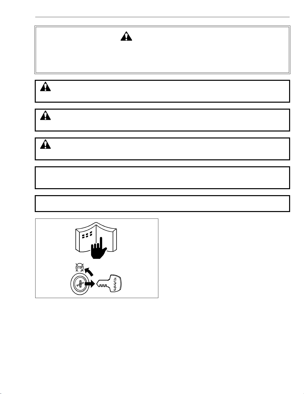
BEFORE SERVICING AND REPAIRING
• Read all instructions and safety instructions in this
manual and on your machine safety decals.
• Clean the work area and machine.
• Park the machine on a firm and level ground, and set
the parking brake.
• Lower the implement to the ground.
• Stop the engine, and remove the key.
• Disconnect the battery negative cable.
• Hang a “DO NOT OPERATE” tag in operator
station.
L1
Page 4
M9540Low Profile, WSM
KiSC issued 09, 2008 A
SAFETY INSTRUCTIONS
SAFETY STARTING
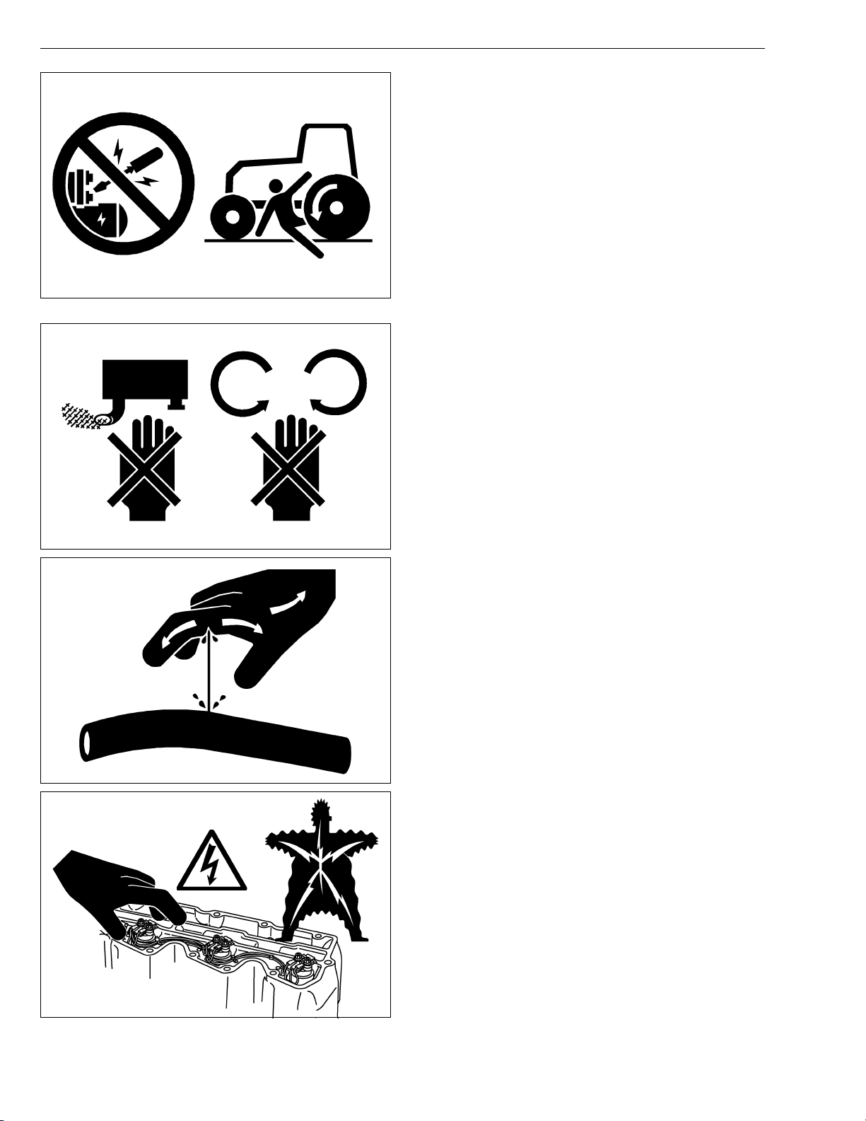
• Do not start the engine by shorting across starter
terminals or bypassing the safety start switch.
• Do not alter or remove any part of machine safety
system.
• Before starting the engine, make sure that all shift
levers are in neutral positions or in disengaged
positions.
• Never start the engine while standing on ground.
Start the engine only from operator’s seat.
SAFETY WORKING
• Do not work on the machine while under the influence
of alcohol, medication, or other substances or while
fatigued.
• Wear close fitting clothing and safety equipment
appropriate to the job.
• Use tools appropriate to the work. Makeshift tools,
parts, and procedures are not recommended.
• When servicing is performed together by two or more
persons, take care to perform all work safely.
• Do not work under the machine that is supported
solely by a jack. Always support the machine by
safety stands.
• Do not touch the rotating or hot parts while the engine
is running.
• Never remove the radiator cap while the engine is
running, or immediately after stopping. Otherwise, hot
water will spout out from radiator. Only remove
radiator cap when cool enough to touch with bare
hands. Slowly loosen the cap to first stop to relieve
pressure before removing completely.
• Escaping fluid (fuel or hydraulic oil) under pressure
can penetrate the skin causing serious injury. Relieve
pressure before disconnecting hydraulic or fuel lines.
Tighten all connections before applying pressure.
• Do not open high-pressure fuel system.
High-pressure fluid remaining in fuel lines can cause
serious injury. Do not disconnect or attempt repair
fuel lines, sensors, or any other components between
the high-pressure fuel pump and injectors on engines
with high pressure common rail fuel system.
• High voltage exceeding 100 V is generated in the
ECU, and is applied to the injector.
Pay sufficient caution to electric shock when
performing work activities.
L2
Page 5
M9540Low Profile, WSM
KiSC issued 09, 2008 A
SAFETY INSTRUCTIONS
AVOID FIRES
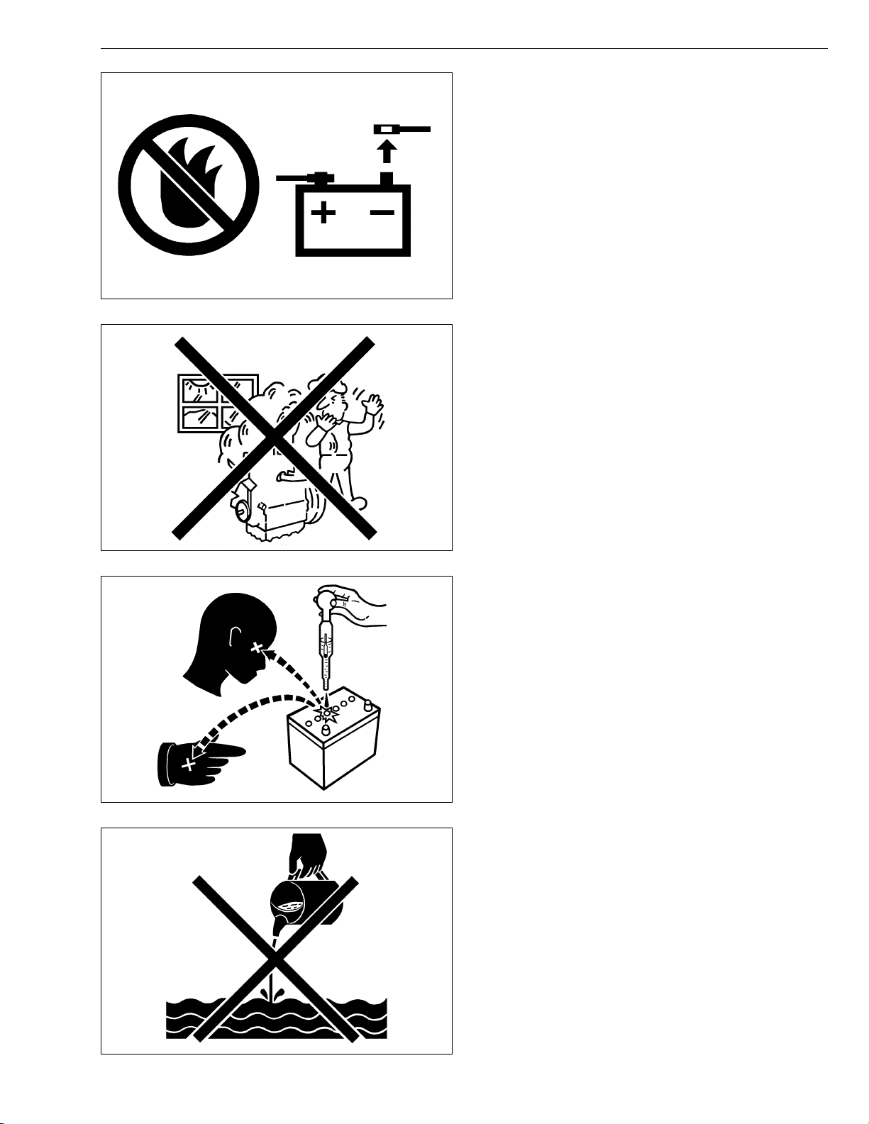
• Fuel is extremely flammable and explosive under
certain conditions. Do not smoke or allow flames or
sparks in your working area.
• To avoid sparks from an accidental short circuit,
always disconnect the battery negative cable first and
connect it last.
• Battery gas can explode. Keep sparks and open
flame away from the top of battery, especially when
charging the battery.
• Make sure that no fuel has been spilled on the engine.
VENTILATE WORK AREA
• If the engine must be running to do some work, make
sure the area is well ventilated. Never run the engine
in a closed area. The exhaust gas contains poisonous
carbon monoxide.
PREVENT ACID BURNS
• Sulfuric acid in battery electrolyte is poisonous. It is
strong enough to burn skin, clothing and cause
blindness if splashed into eyes. Keep electrolyte
away from eyes, hands and clothing. If you spill
electrolyte on yourself, flush with water, and get
medical attention immediately.
DISPOSE OF FLUIDS PROPERLY
• Do not pour fluids into the ground, down a drain, or
into a stream, pond, or lake. Observe relevant
environmental protection regulations when disposing
of oil, fuel, coolant, electrolyte and other harmful
waste.
L3
Page 6
M9540Low Profile, WSM
KiSC issued 09, 2008 A
SAFETY INSTRUCTIONS
PREPARE FOR EMERGENCIES
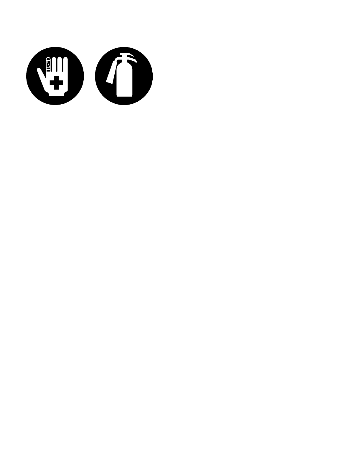
• Keep a first aid kit and fire extinguisher handy at all
times.
• Keep emergency numbers for doctors, ambulance
service, hospital and fire department near your
telephone.
L4
Page 7
M9540Low Profile, WSM
KiSC issued 09, 2008 A
SAFETY INSTRUCTIONS
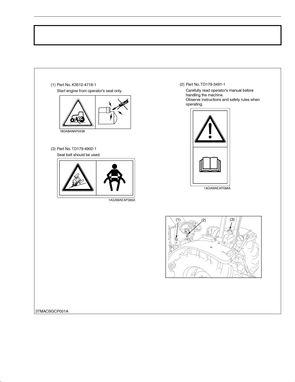
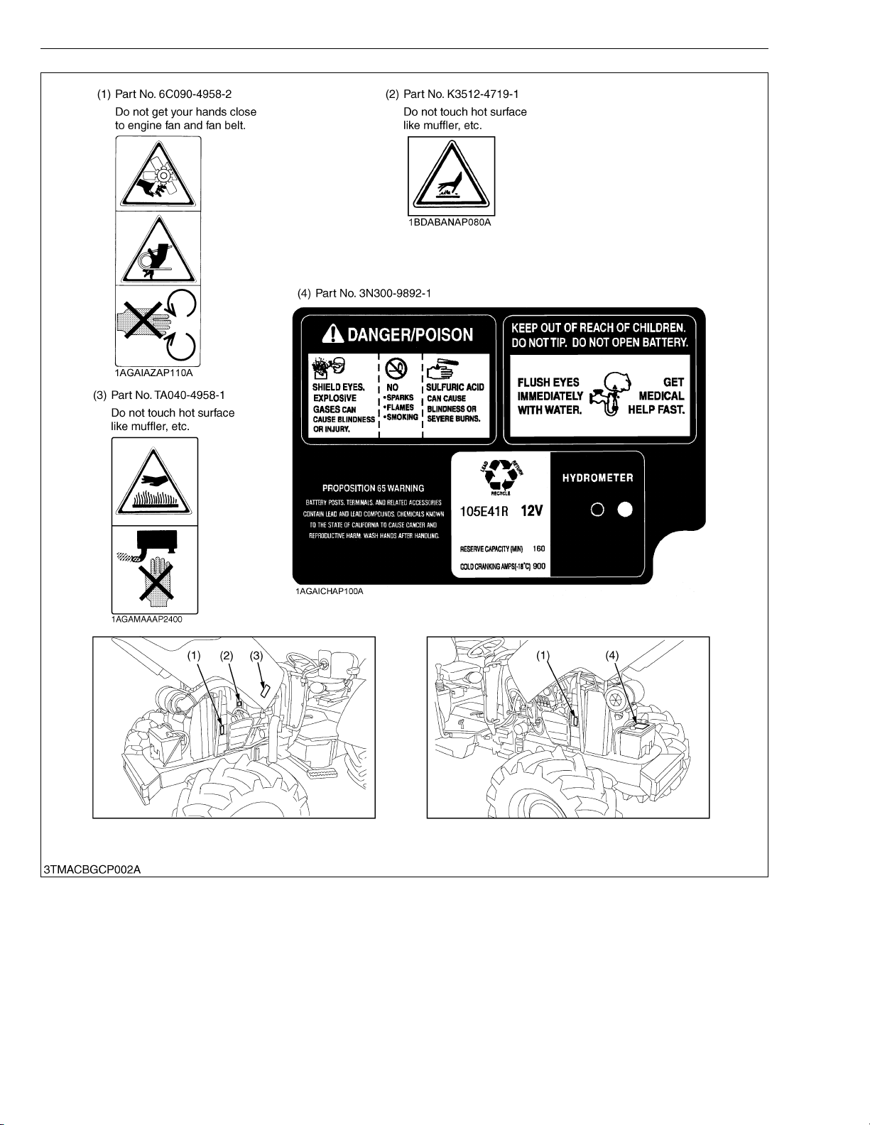
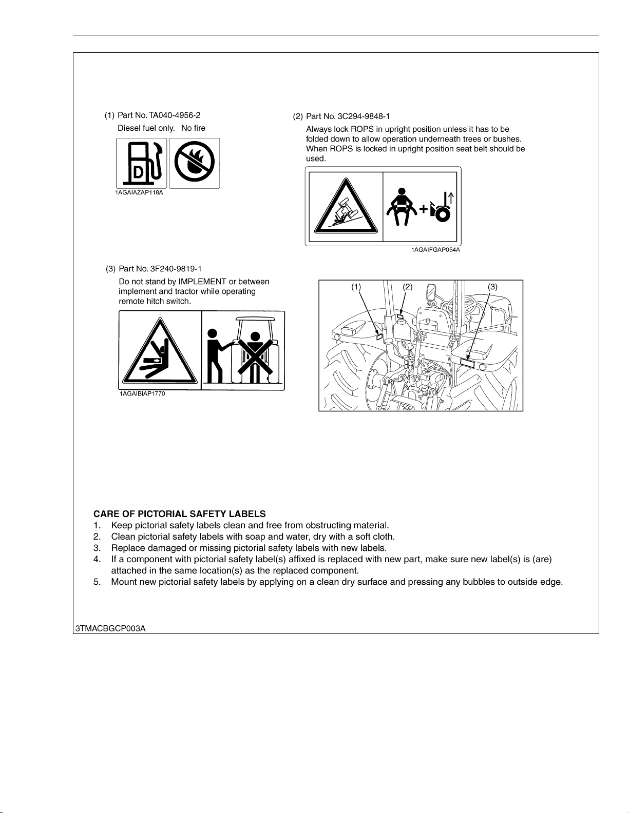
SAFETY DECALS
The following safety decals (pictrical safety labals) are installed on the machine.
If a decal becomes damaged, illegible or is not on the machine, replace it. The decal part number is listed in
the parts list.
L5
Page 8
M9540Low Profile, WSM
KiSC issued 09, 2008 A
SAFETY INSTRUCTIONS
L6
Page 9
M9540Low Profile, WSM
KiSC issued 09, 2008 A
SAFETY INSTRUCTIONS
L7
Page 10
M9540Low Profile, WSM
KiSC issued 09, 2008 A
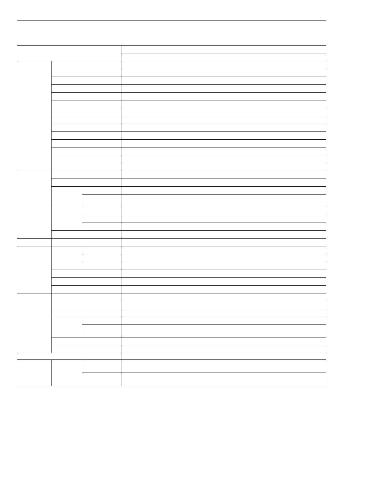
SPECIFICATIONS
SPECIFICATIONS
Model
M9540Low Profile
4WD
Model V3800DI-TE3
Type Vertical, water-cooled, 4-cycle direct injection diesel engine
Number of cylinders 4
3
Total displacement 3769 cm
(230.0 cu.in.)
Bore and stroke 100 × 120 mm (3.9 × 4.7 in.)
−1
(rpm)
Engine
Rated speed 2600 min
Net power
Gross power
*1
*1
70.8 kW (95.0 HP)
73.6 kW (98.7 HP)
Maximum torque 314 N·m (32.0 kgf·m, 232 lbf·ft) / 1500 to 1700 min
Battery capacity 12 V, RC : 160 min, CCA : 900 A
Fuel Diesel fuel No. 1 [below −10 °C (14 °F], Diesel fuel No. 2-D [above −10 °C (14 °F)]
Fuel tank capacity 90 L (23.8 U.S.gals., 19.8 Imp.gals.)
Engine oil capacity 10.7 L (11.3 U.S.qts., 9.4 Imp.qts.)
Coolant capacity 9.0 L (9.5 U.S.qts., 7.9 Imp.qts.)
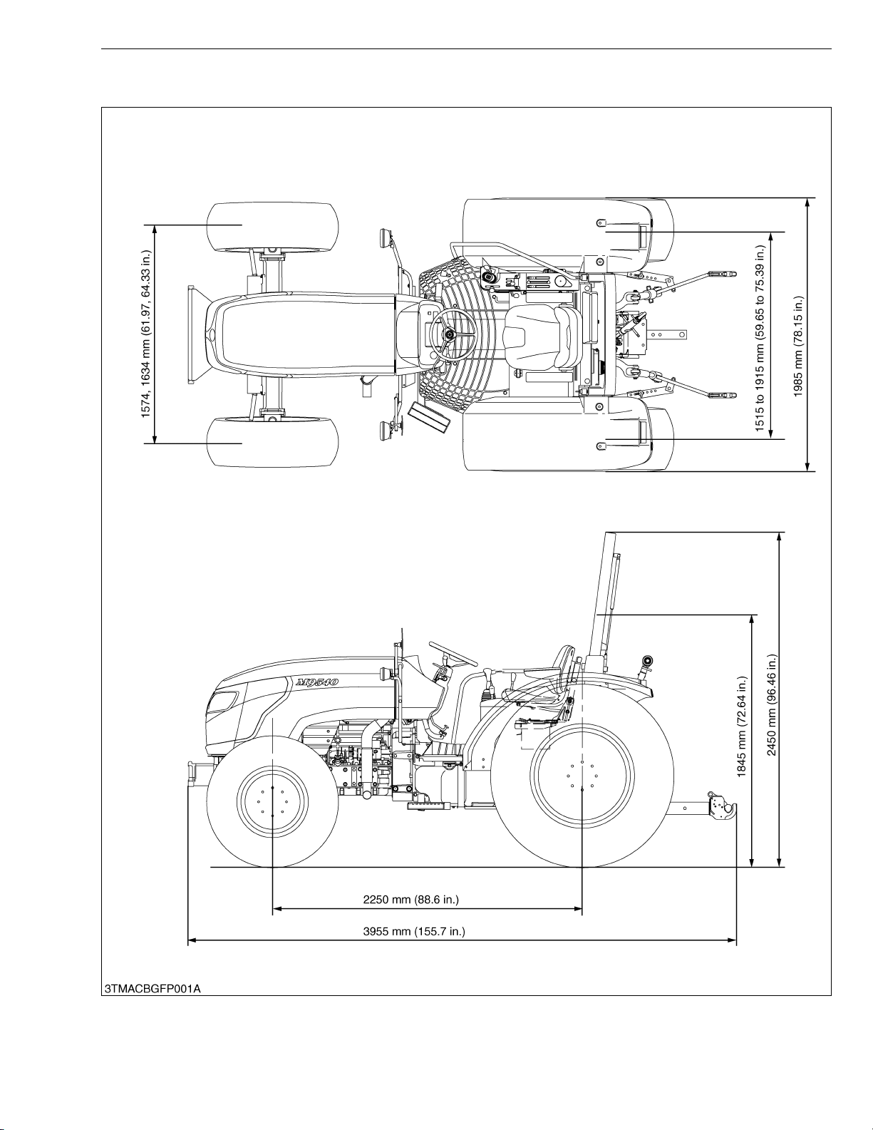
Overall length 3955 mm (155.7 in.)
Overall width (min. tread) 1985 mm (78.15 in.)
ROPS raised 2450 mm (96.46 in.)
ROPS
retracted
1845 mm (72.64 in.)
Dimensions
Overall
height
Wheel base 2250 mm (88.6 in.)
Tread
Front 1574, 1634 mm (61.97, 64.33 in.)
Rear 1515 to 1915 mm (59.65 to 75.39 in.)
Minimum ground clearance 390 mm (15.4 in.) (Drawbar bracket)
Weight Standard tire with steel disc 2900 kg (6393 lbs)
Front 360/70R20
Rear 480/70R28
Traveling
system
Standard
tire size
Clutch Multiple wet discs
Steering Hydraulic power steering
Braking system Hydraulic wet discs
Differential Bevel gears with differential lock (Rear)
Hydraulic control system Position, draft (top link sensing) and mix control
Pump capacity 64.3 L (17 U.S.gals., 14 Imp.gals.) / min.
3-point hitch SAE Category II
Hydraulic
system
Max. lifting
force
At lift points
24 in. behind lift
points
*2
*2
3900 kg (8598 lbs)
3300 kg (7275 lbs)
Remote hydraulic control Two remote valve (Max Three)
2
System pressure 19.6 MPa (200 kgf/cm
, 2844.7 psi)
Traction system Swinging drawbar, adjustable in direction
PTO
Live PTO
(Indipendent)
Direction of
turning
PTO speed
6 spline : 540 min
6 spline : 540E min
Clockwise, viewed from tractor rear
−1
(rpm) / 2035 min−1 (rpm) engine speed
−1
(rpm) / 1519 min−1 (rpm) engine speed
Note : *1 : Manufacture’s estimate
*2 : At lower link end with links horizontal.
The company reserves the right to change the specifications without notice.
−1
(rpm)
W10281170
L8
Page 11

M9540Low Profile, WSM
KiSC issued 09, 2008 A
TRAVELING SPEEDS
Model
Tire size (Rear) 480/70R28
Shuttle shift
lever
Forward
The company reserves the right to change the specifications without notice.
Range gear shift
lever
CREEP
L
H
Main gear shift
lever
1 0.39 (0.24)
2 0.50 (0.31)
3 0.66 (0.41)
4 0.84 (0.52)
5 1.04 (0.646)
6 1.29 (0.802)
1 2.5 (1.6)
2 3.2 (2.0)
3 4.2 (2.6)
4 5.4 (3.4)
5 6.7 (4.2)
6 8.4 (5.2)
1 9.7 (6.0)
2 12.4 (7.70)
3 16.4 (10.2)
4 21.0 (13.0)
5 26.0 (16.2)
6 32.3 (20.1)
TRAVELING SPEEDS
(At rated engine rpm)
M9540Low Profile
F18/R18 model
km/h (mph)
W1035065
L9
Page 12

M9540Low Profile, WSM
KiSC issued 09, 2008 A
Model
Tire size (Rear) 480/70R28
Shuttle shift
lever
Range gear shift
lever
Main gear shift
lever
1 0.39 (0.24)
2 0.49 (0.30)
3 0.65 (0.40)
CREEP
4 0.83 (0.52)
5 1.03 (0.640)
6 1.28 (0.795)
1 2.5 (1.6)
2 3.2 (2.0)
3 4.2 (2.6)
Reverse
L
4 5.4 (3.4)
5 6.7 (4.2)
6 8.3 (5.2)
1 9.6 (6.0)
2 12.4 (7.70)
3 16.3 (10.1)
H
4 20.9 (13.0)
5 25.8 (16.0)
6 32.1 (19.9)
The company reserves the right to change the specifications without notice.
TRAVELING SPEEDS
(At rated engine rpm)
M9540Low Profile
F18/R18 model
km/h (mph)
W1034678
L10
Page 13
M9540Low Profile, WSM
KiSC issued 09, 2008 A
DIMENSIONS
DIMENSIONS
L11
Page 14

LG GENERAL
KiSC issued 09, 2008 A
Page 15

GENERAL
KiSC issued 09, 2008 A
CONTENTS
1. TIRES............................................................................................................. LG-1
[1] TIRE SIZE AND INFLATION PRESSURE ........................................... LG-1
[2] TREAD ADJUSTMENT........................................................................... LG-1
(1) Front Wheels...................................................................................... LG-2
(2) Rear Wheels ...................................................................................... LG-3
[3] TIRE LIQUID INJECTION ...................................................................... LG-4
Page 16
M9540Low Profile, WSM
KiSC issued 09, 2008 A
G GENERAL
1. TIRES
WARNING
• Do not attempt to mount a tire on a rim. This should be done by a qualified person with the proper
equipment.
• Always maintain the correct tire pressureìo not inflate tires above the recommended pressure shown in
the operator’s manual.
IMPORTANTQ
• Do not use tires other than those approved by KUBOTA.
• Dual tires are not approved.
NOTEQ
• When optional different-diameter tires are fitted on the machine, the travel speed display mode must be
changed. Otherwise the travel speed will not get correctly displayed. Such mode switching is also needed
when the original tires are back on the machine. (Refer to “4. CHECKING AND ADJUSTING” at “L9.
ELECTRICAL SYSTEM” section in this manual.)
[1] TIRE SIZE AND INFLATION PRESSURE
IMPORTANTQ
• Excessive wear of tires may occur due to improper gear ratio.
Through the tire pressure is factory-set to the prescribed level, it
naturally drops slowly in the course of time. Thus, check it every day
and inflate as necessary.
Q Recommended Inflation Pressure
• Maintain the pressure shown below for normal use.
Tire sizes Inflation pressure
Front 360/70R20 160 kPa (1.6 kgf/cm
Rear 480/70R28 120 kPa (1.2 kgf/cm
2
, 23 psi)
2
, 18 psi)
NOTEQ
• Maintain the maximum pressure in front tires, if using a front
loader of when equipped with lots of front weight.
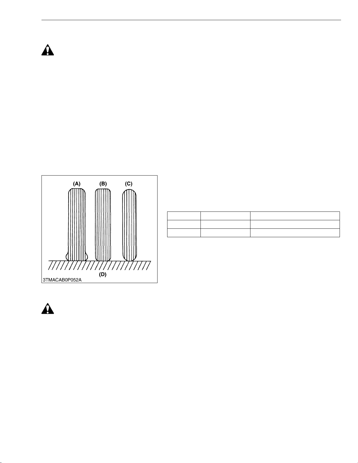
(A) Insufficient
(B) Standard
(C) Excessive
(D) Ground
W1027488
[2] TREAD ADJUSTMENT
CAUTION
• When working on slopes or when working with trailer, set the wheel tread as wide as practical for maximum
stability.
• Support tractor securely on stands before removing a wheel.
• Do not work under any hydraulically supported devices. They can settle, suddenly leak down, or be
accidentally lowered. If necessary to work under tractor or any machine elements for servicing or
adjustment, securely support them with stands or suitable blocking beforehand.
• Never operate tractor with a loose rim, wheel, or axle.
LG-1
Page 17
M9540Low Profile, WSM
KiSC issued 09, 2008 A
(1) Front Wheels
G GENERAL
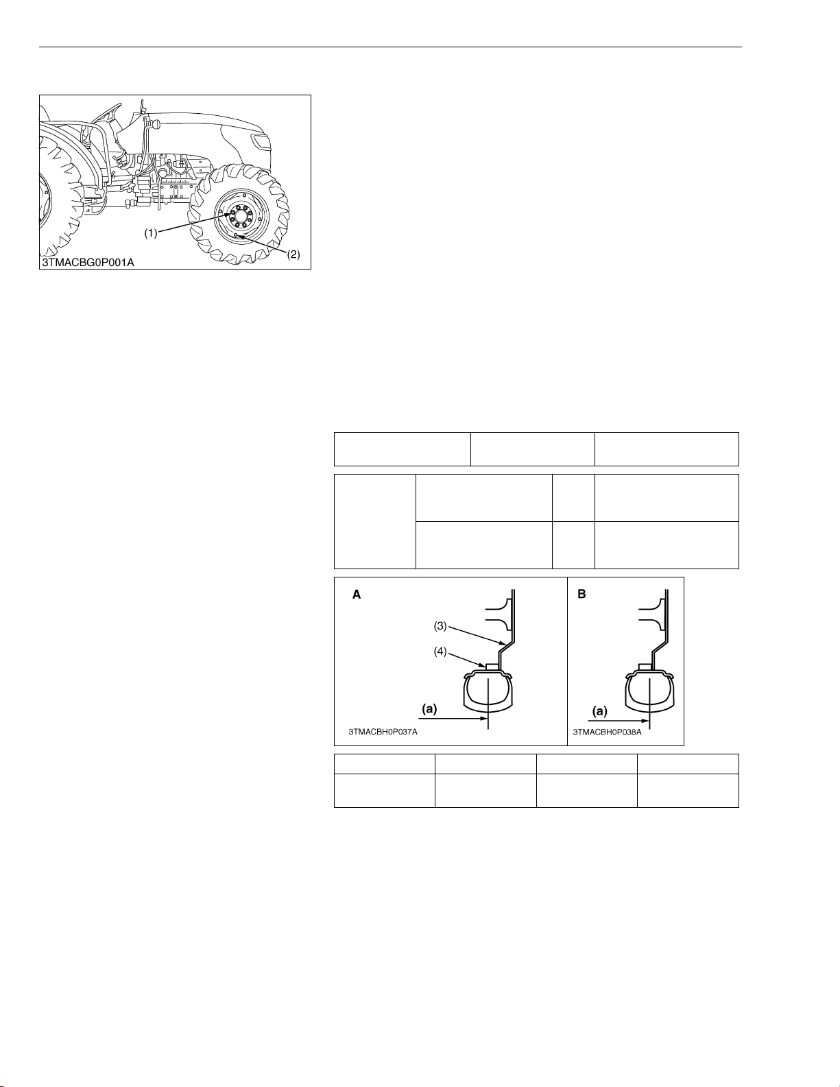
Front tread width can be adjusted as shown with the standard
equipped tires.
To change the tread width
1. Remove the wheel rim and disc mounting bolts.
2. Change the position of the rim and disc (right and left) to the
desired position, and tighten the bolts.
3. Adjust the toe-in. (Refer to “[5] CHECK POINTS OF EVERY
200 HOURS” at “7. CHECK AND MAINTENANCE”.)
IMPORTANTQ
• Always attach wheels as shown in the figure.
• If not attached as illustrated, transmission parts may be
damaged.
• When re-fitting or adjusting a wheel, tighten the bolts to the
following torques then recheck after driving the tractor 200
m (200 yards) and thereafter according to service interval.
(Refer to “[5] CHECK POINTS OF EVERY 50 HOURS” at
“7. CHECK AND MAINTENANCE”.)
NOTEQ
• Wheels with beveled or tapered holes: use the tapered side
of lug nut.
Toe-in Factory spec.
2.0 to 8.0 mm
0.08 to 0.31 in.
Front wheel mounting
Tightening
torque
Tread (a) 360/70R20
(1) Front Wheel Mounting Nut
(2) Front Disc Mounting Nut
(3) Front Wheel Disc
(4) Front Wheel Rim
nut
Front disc mounting nut M16
259.9 to 304.0 N·m
M16
Tire A B
1574 mm
61.97 in.
(a) Tread
26.5 to 31.0 kgf·m
191.7 to 224.2 lbf·ft
259.9 to 304.0 N·m
26.5 to 31.0 kgf·m
191.7 to 224.2 lbf·ft
1634 mm
64.33 in.
W1039833
LG-2
Page 18
M9540Low Profile, WSM
KiSC issued 09, 2008 A
(2) Rear Wheels
G GENERAL
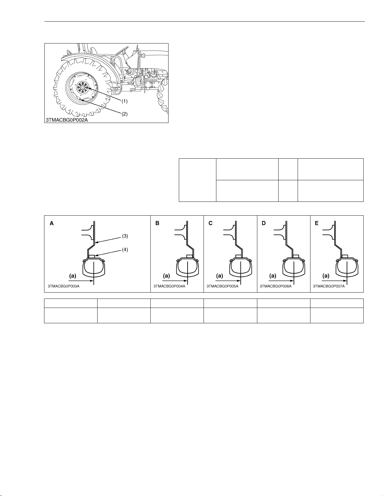
Rear tread width can be adjusted as shown with the standard
equipped tires.
To change the tread width
1. Remove the wheel rim and / or disc mounting bolts.
2. Change the position of the rim and disc (right and left) to the
desired position, and tighten the bolts.
IMPORTANTQ
• Always attach wheels as shown in the figure.
• If not attached as illustrated, transmission parts may be
damaged.
• When re-fitting or adjusting a wheel, tighten the bolts to the
following torques then recheck after driving the tractor 200
m (200 yards) and thereafter according to service interval.
(Refer to “[5] CHECK POINTS OF EVERY 50 HOURS” at
“7. CHECK AND MAINTENANCE”.)
343 to 401 N·m
35.0 to 41.0 kgf·m
254 to 297 lbf·ft
259.9 to 304.0 N·m
26.5 to 31.0 kgf·m
191.7 to 224.2 lbf·ft
W1082792
Tightening
torque
Rear wheel mounting
nut
Rear disc mounting nut M16
M18
Tread (a) A B C D E
480/70R28
(1) Rear Wheel Mounting Nut
(2) Rear Disc Mounting Nut
1515 mm
59.65 in.
(3) Rear Wheel Disc (4) Rear Wheel Rim (a) Tread
1585 mm
62.40 in.
1723 mm
67.83 in.
1777 mm
69.96 in.
1915 mm
75.39 in.
LG-3
Page 19
M9540Low Profile, WSM
KiSC issued 09, 2008 A
G GENERAL
[3] TIRE LIQUID INJECTION
Auxiliary weights can be used to increase traction force for plowing in fields or clayey ground.
Another way is to inject water or another liquid, such as a calcium chloride solution in the tires. Water must not be
used in winter since it freezes at 0 °C (32 °F). The calcium chloride solution will not freeze and moreover, affords
higher effect than water since its specific gravity is higher than that of water by about 20 %. Below is an explanation
of calcium chloride solution injection.
IMPORTANTQ
• Do not fill the front tires with liquid.
Injection
CAUTION
• When a calcium chloride solution is used, cool it before
pouring it into the tire.
• Do not fill tires with water or solution more than 75 % of full
capacity (to the valve stem level).
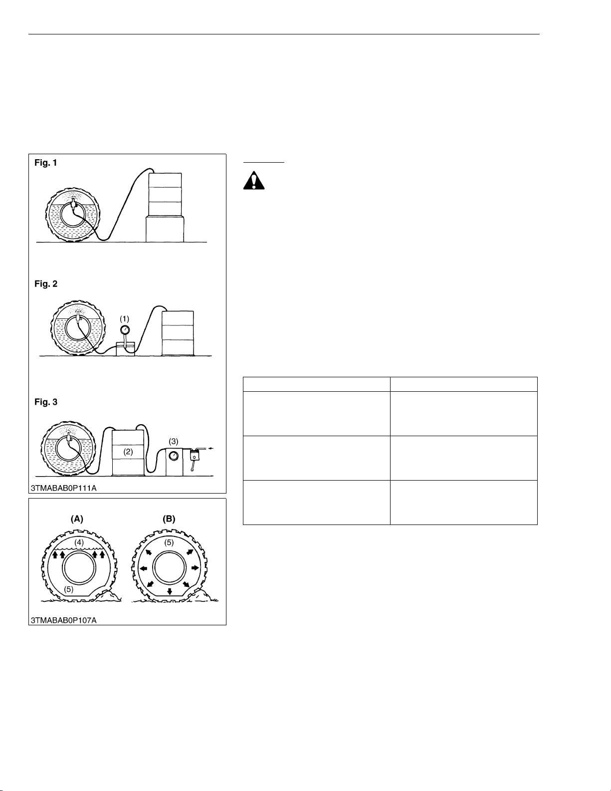
The following four ways can be used to inject water or a calcium
chloride solution into tires.
1. Gravity injection (Fig. 1)
2. Pump injection (Fig. 2)
3. Pressure tank injection (Fig. 3)
4. Injection directly from tap (only when water is being used).
NOTEQ
• Once injection is completed, reset the air valve, and pump
air into the tire to the specified pressure.
Weight of Calcium Chloride Solution Filling 75 % of Full Capacity
of a Tire
Tire sizes 480/70R28
Slush free at −10 °C (14 °F)
Solid at −30 °C (−22 °F)
[Approx. 1 kg (2 lbs.) CaCl
(1 gal.) of water]
Slush free at −24 °C (−11 ° F )
Solid at −47 °C (−53 °F)
[Approx. 1.5 kg (3.5 lbs.) CaCl
4 L (1 gal.) of water]
Slush free at −47 °C (−53 °F)
Solid at −52 °C (−62 °F)
[Approx. 2.25 kg (5 lbs.) CaCl
(1 gal.) of water]
2 per 4 L
2 per
2 per 4 L
328 kg
723 lbs
400 kg
882 lbs
424 kg
935 lbs
(1) Pump
(2) Pressure Tank
(3) Compressor
(4) Air
(5) Water
LG-4
(A) Correct : 75 %
Air Compresses Like A Cushion
(B) Incorrect : 100 % Full
Water Can Not Be Compressed
W1033435
Page 20

L3 TRANSMISSION
KiSC issued 09, 2008 A
Page 21

MECHANISM
KiSC issued 09, 2008 A
CONTENTS
1. STRUCTURE ............................................................................................... L3-M1
[1] F18/R18 SPEED TRANSMISSION MODEL ....................................... L3-M1
2. POWER TRAIN FOR TRAVELING GEAR............................................... L3-M2
[1] BI-SPEED TURN SYSTEM.................................................................. L3-M2
(1) 2WD-4WD-Bi-speed Turn ................................................................ L3-M2
(2) Solenoid Valve ................................................................................. L3-M4
(3) 4WD / Bi-speed Turn Oil Flow ......................................................... L3-M5
Page 22
M9540Low Profile, WSM
KiSC issued 09, 2008 A
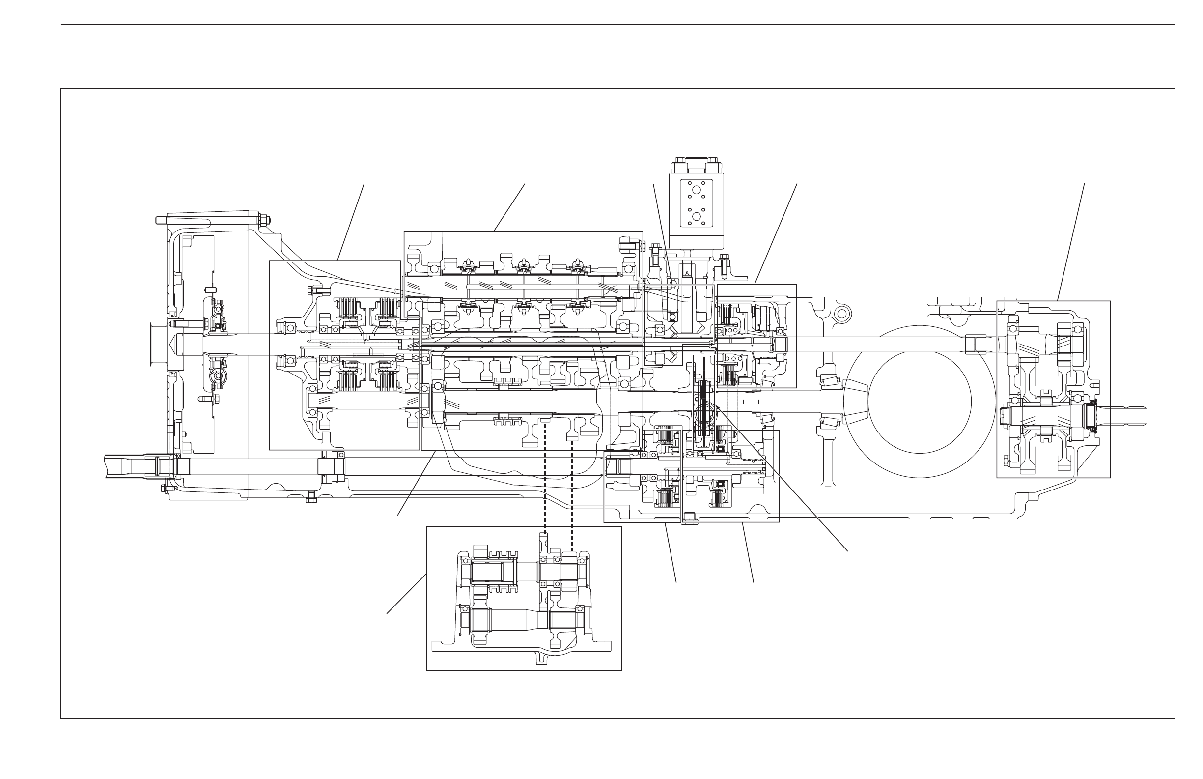
1. STRUCTURE
[1] F18/R18 SPEED TRANSMISSION MODEL
TRANSMISSION
(1) (2) (3) (4) (5)
3TMACBG3P001A
(1) Hydraulic Shuttle Section
(2) Main Gear Shift Section
(3) Hydraulic Pump Drive Section
(4) PTO Clutch Section
(10)
(9)
(5) PTO Gear Section
(6) Parking Brake Section
L3-M1
(7) Bi-Speed Section
(8) 2WD-4WD Section
(6)
(8) (7)
(9) Creep Section
(10) Auxiliary Gear Shift Section
Page 23
M9540Low Profile, WSM
KiSC issued 09, 2008 A
2. POWER TRAIN FOR TRAVELING GEAR
[1] BI-SPEED TURN SYSTEM
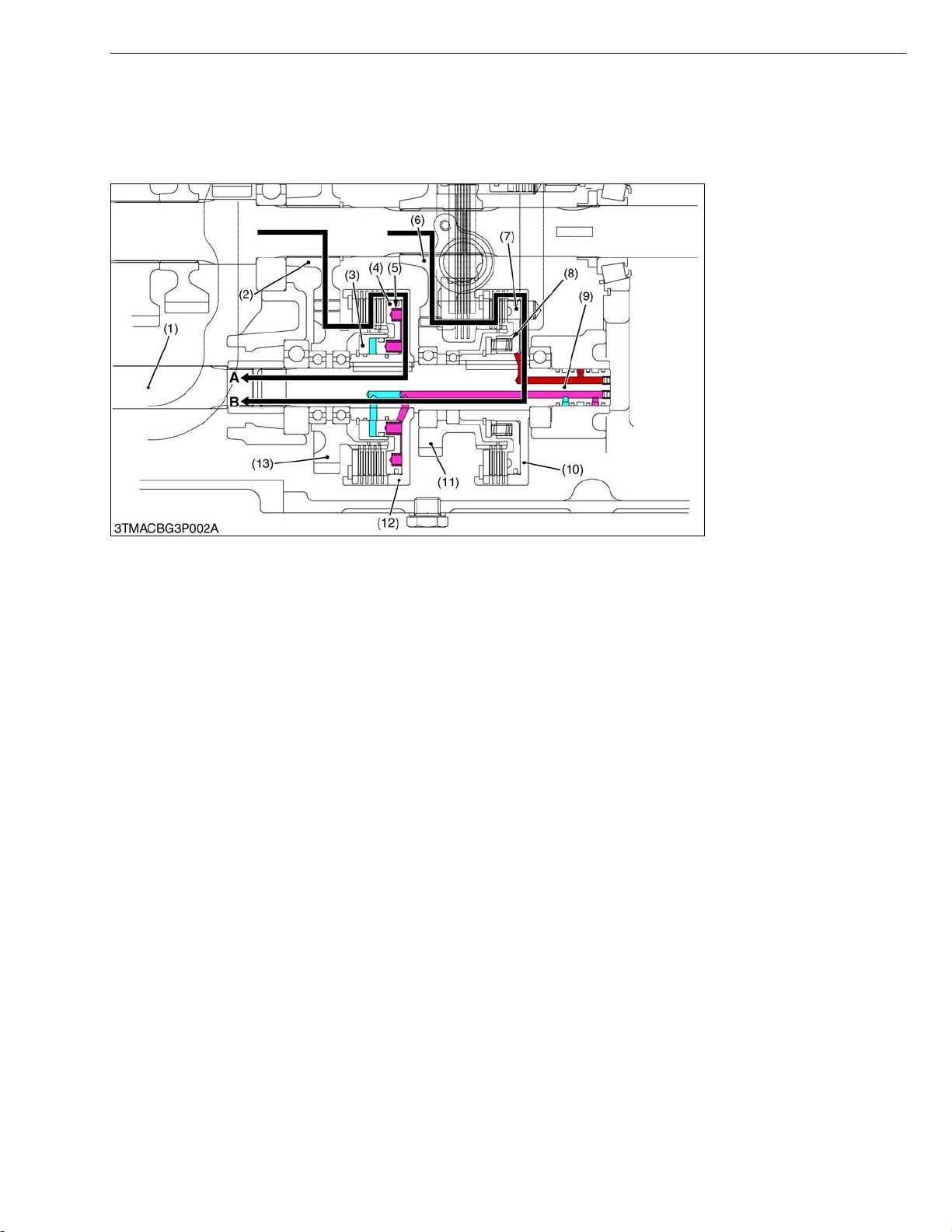
(1) 2WD-4WD-Bi-speed Turn
TRANSMISSION
(1) DT Propeller Shaft
(2) 33T Gear
(3) Neutral Cover
(4) 4WD Piston
(5) Spring
(6) 47T Gear
(7) Bi-speed Turn Piston
(8) Return Spring
(9) 4WD / Bi-speed Turn Shaft
(10) Clutch Body (Bi-Speed)
(11) 33T Gear
(12) Clutch Body (4WD)
(13) 35T Gear
A : 4WD
B : Bi-speed Turn
W1012704
The Bi-speed turn clutch is controlled by the combination of the solenoid valve and the hydraulic flow.
When the 4WD / Bi-speed turn switch is pushed once, the front wheel drive (4WD) is engaged. When it is pushed
twice, the Bi-speed turn system works. When it is pushed once more, the 2-wheel drive is engaged. The power train
are available as follows.
2-wheel drive (4WD / Bi-speed turn switch is turned to “OFF”)
• The hydraulic system pressure is fed to between the neutral cover (3) and 4WD piston (4) at 4WD switch is turned
to “OFF” and hydraulic pressure does not come from 4WD solenoid valve to actuate the 4WD piston (4). So, the
hydraulic system pressure actuate the 4WD piston (4) to the neutral position and power is not transmitted from 33T
gear (2) to DT propeller shaft (1).
• When both brake pedals are depressed together while driving in 2WD mode, 2-brake switch operate the 4WD
solenoid valve and activate to the 4WD mode. 4WD mode activate the 4WD braking system and the 4WD indicator
lights up.
4-wheel drive (4WD / Bi-speed turn switch is turned to “4WD”)
• The 4WD / Bi-speed turn solenoid valve switches and supply the hydraulic pressure to actuate the 4WD piston (4)
to engage the clutch pack together with the spring (5) tension force.
The power is transmitted as follow.
33T Gear (2) → 35T Gear (13) → Clutch Body (4WD) (12) → 4WD / Bi-speed Turn Shaft (9) → DT Propeller Shaft
(1).
Engine stop
• The 4WD piston (4) engage to 4WD mode by spring (5) tension force and maintain the 4WD mode.
Bi-speed turn drive (4WD / Bi-speed turn switch is turned to “Bi-speed turn”)
• When front wheels reach approximately 0.56 rad (32 °) turning angle, its turning angle inspection switch is pushed
to “ON” position and solenoid valve is operated. As a result, the Bi-speed turn is hydraulically engaged and the
front wheel is revolved 1.5 times as many revolutions as the rear one.
• Bi-speed turn operates during the 0.1 to 9.5 km/h (0.063 to 5.9 m/h) traveling speed with 480/70R-28 rear tire.
When the traveling speed is not within the specified speed, Bi-speed turn does not operated.
47T Gear (6) → 33T Gear (11) → Clutch Body (Bi-speed) (10) → 4WD / Bi-speed Turn Shaft (9) → DT Propeller
Shaft (1).
L3-M2
Page 24
M9540Low Profile, WSM
KiSC issued 09, 2008 A
TRANSMISSION
Turning Angle Inspection Switch
The turning angle inspection switch is on the front
wheel case support of left side, and this switch is
controlled “ON” position or “OFF” position of Bi-speed
turn.
When the 4WD / Bi-speed turn switch is set at the Bi-
speed turn position, if the turning angle is less than 0.56
rad (32 °), switch is “OFF” position, and current flows
from the battery to the 4WD solenoid. If the turning angle
exceeds approximately 0.56 rad (32 °), switch is “ON”
position, and current flows to 4WD / Bi-speed turn relay’s
coil, and the relay contact is set to Bi-speed turn position
by electromagnetic force. Therefore, current from the
battery flows to Bi-speed turn solenoid.
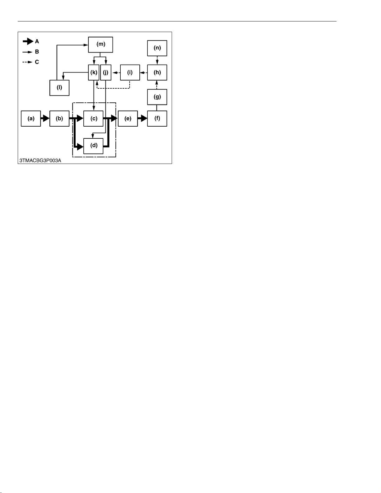
A : Power
B : Oil
C : Electrical Signal
(a) Engine
(b) Transmission Case
(c) 4WD Clutch
(d) Bi-speed Turn Clutch
(e) Front Axle
(f) Front Wheel
(g) Turning Angle Inspection
Switch
(h) 4WD / Bi-speed Turn Relay
(i) 4WD / Bi-speed Turn Switch
(j) 4WD Solenoid Valve
(k) Bi-speed Turn Solenoid
Valve
(l) Oil Reservoir (Transmission
Case)
(m) Hydraulic Pump and Relief
Valve
(n) Brake Pedal Switch
W1013308
L3-M3
Page 25
M9540Low Profile, WSM
KiSC issued 09, 2008 A
(2) Solenoid Valve
TRANSMISSION
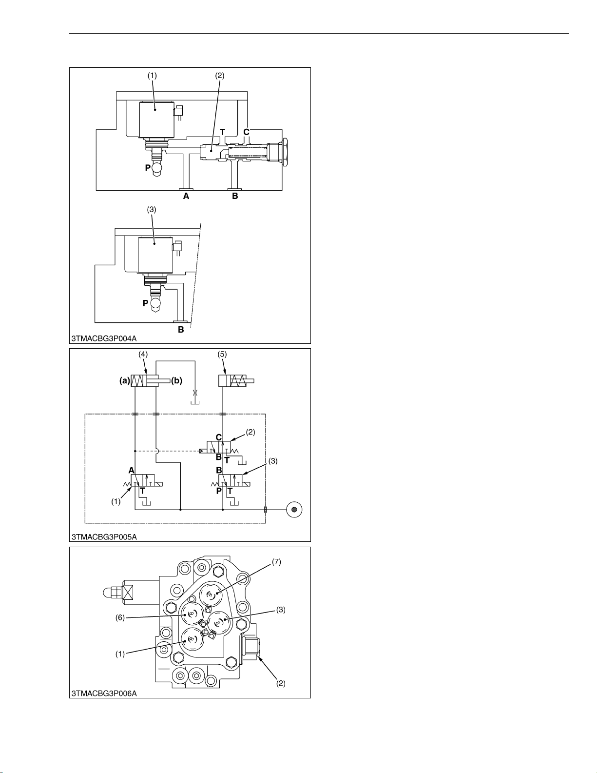
Being not electrified, it is kept in neutral position.
Therefore, oil is flowed to neither Bi-speed turn clutch (5)
nor 4WD clutch (4) when the 4WD / Bi-speed turn switch
is switched to OFF position.
Oil of the hydraulic clutch is drained to the
transmission case through the 4WD clutch (4) 2WD side
(b).
When the 4WD solenoid is electrified, the oil pressure
from the P port to A port to 4WD clutch (4).
And the oil pressure feeds the spool (4WD priority
valve) (2) to change the hydraulic line.
The spool (4WD priority valve) (2) opens Bi-speed
turn clutch (5) and tank port to prevent the 4WD clutch (4)
and Bi-speed clutch (5) are not engage at the same time.
(1) 4WD Solenoid Valve
(2) Spool (4WD Priority Valve)
(3) Bi-speed Solenoid Valve
(4) 4WD Clutch
(5) Bi-speed Turn Clutch
(6) Rear Differential Lock
Solenoid Valve
(7) PTO Solenoid Valve
A : 4WD Port
B : Bi-speed Turn Port
C : Bi-speed Turn Clutch Port
P : From Power Steering Pump
T : To Tank
(a) 4WD Side
(b) 2WD Side
W1018650
L3-M4
Page 26
M9540Low Profile, WSM
KiSC issued 09, 2008 A
(3) 4WD / Bi-speed Turn Oil Flow
TRANSMISSION
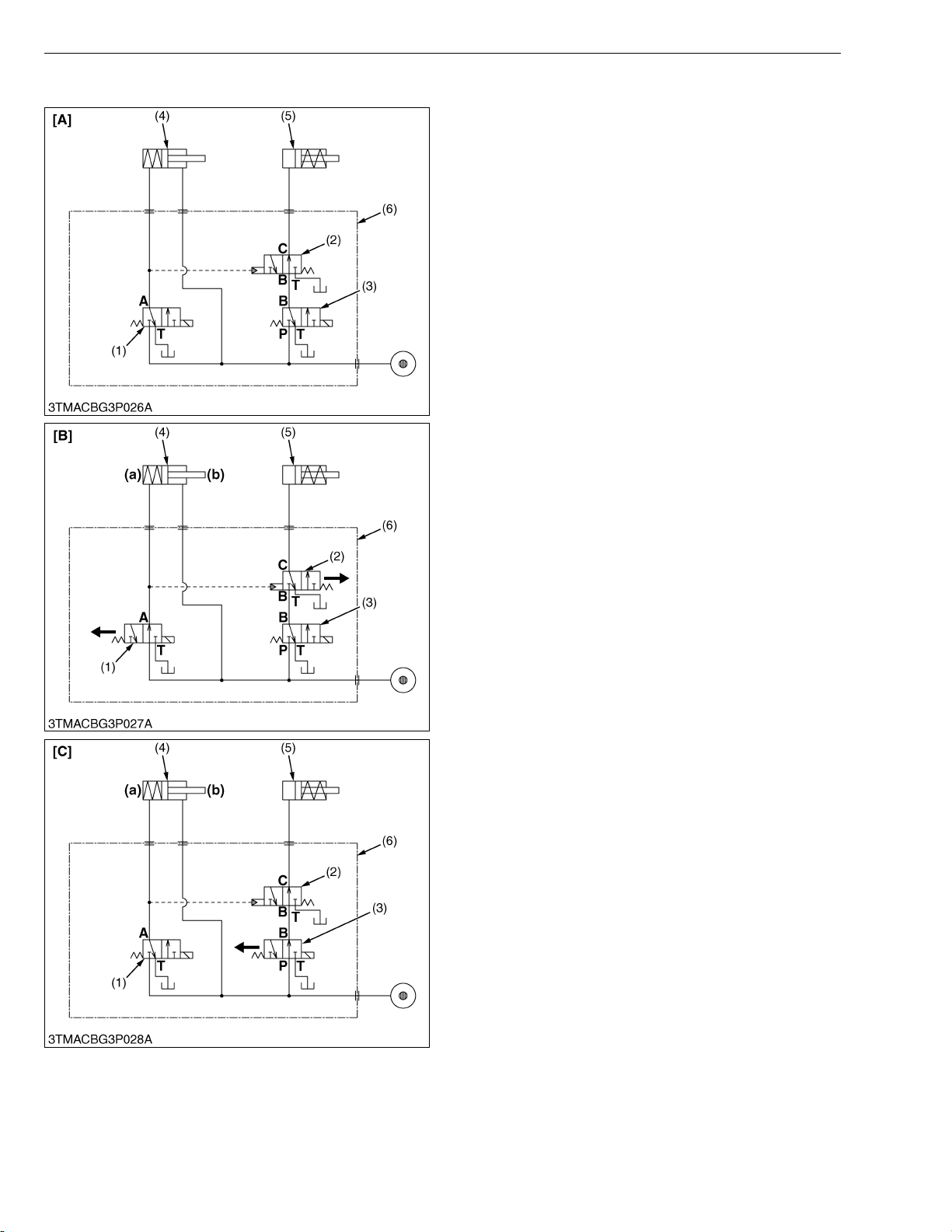
Oil pressure-fed from the power steering hydraulic
pump is flowed to the solenoid valve assembly (6)
through the steering controller and oil cooler. The
system hydraulic pressure-fed to disengaged position for
2WD-4WD clutch (4) when 4WD / Bi-speed turn switch at
2WD position. As the 4WD (1) or Bi-speed turn (3) the
solenoid valve is electrified, the oil flow is switched and
either Bi-speed turn clutch or 4WD clutch is engaged.
When the Bi-speed turn solenoid valve (3) shift to Bispeed turn side, the 4WD priority valve (2) effect to
reduce the engagement shock of clutch pack.
The maximum pressure against the clutch piston is
2
regulated under approx. 2.45 MPa (25.0 kgf/cm
, 356
psi) by the relief valve of PTO clutch valve.
On the other hand, the return oil is flowed to the
transmission case through the solenoid valve assembly
(7).
(1) 4WD Solenoid Valve
(2) 4WD Priority Valve
(3) Bi-speed Solenoid Valve
(4) 2WD-4WD Clutch
(5) Bi-speed Turn Clutch
(6) Solenoid Valve Assembly
A : 4WD Port
B : Bi-speed Turn Port
[A] 2WD
[B] 4WD
[C] Bi-speed Turn (4WD)
(a) 4WD Side
(b) 2WD Side
P : From Power Steering Pump
T : To Tank
W1014207
L3-M5
Page 27

SERVICING
KiSC issued 09, 2008 A
CONTENTS
1. SERVICING SPECIFICATIONS ..................................................................L3-S1
2. CHECKING AND ADJUSTING ...................................................................L3-S2
[1] MAIN GEAR SHIFTING ........................................................................L3-S2
[2] BI-SPEED TURN SYSTEM...................................................................L3-S3
3. DISASSEMBLING AND ASSEMBLING ......................................................L3-S4
[1] HYDRAULIC SHUTTLE VALVE ...........................................................L3-S4
(1) Removing Fuel Tank.........................................................................L3-S4
[2] ROPS ......................................................................................................L3-S7
[3] 4WD CLUTCH PACK AND BI-SPEED TURN CLUTCH PACK .......L3-S9
(1) Separating Transmission Case and Clutch Housing Case ...............L3-S9
(2) 4WD Clutch Pack and Bi-Speed Turn Clutch Pack ..........................L3-S9
4. SERVICING ................................................................................................L3-S12
[1] 4WD / BI-SPEED TURN CLUTCH PACK ..........................................L3-S12
Page 28

M9540Low Profile, WSM
KiSC issued 09, 2008 A
1. SERVICING SPECIFICATIONS
Main Shift Rod
Item Factory Specification Allowable Limit
Main Shift Rod 1
Length
322 mm
12.7 in.
TRANSMISSION
–
Main Shift Rod 2
Length
178 mm
7.008 in.
4WD/Bi-Speed Turn System
Hydraulic System Pressure for Shuttle and
2WD-4WD-Bi-speed Turn
Pressure 2.06 to 2.15 MPa
21.0 to 22.0 kgf/cm
299 to 312 psi
Clutch Disc
(Both 4WD Side and Bi-speed Turn Side)
Steel Plate
(Both 4WD Side and Bi-speed Turn Side)
Pressure Plate
(Both 4WD Side and Bi-speed Turn Side)
Piston
Thickness 2.1 to 2.3 mm
0.083 to 0.090 in.
Thickness 1.67 to 1.83 mm
0.0658 to 0.0720 in.
Thickness 4.42 to 4.58 mm
0.174 to 0.180 in.
Flatness – 0.15 mm
(Both 4WD Side and Bi-speed Turn Side)
Steel Plate
Flatness – 0.40 mm
(Both 4WD Side and Bi-speed Turn Side)
Pressure Plate
Flatness – 0.30 mm
(Both 4WD Side and Bi-speed Turn Side)
Seal Ring Thickness 2.39 to 2.44 mm
0.0941 to 0.0960 in.
–
W1013874
–
2
1.9 mm
0.090 in.
1.3 mm
0.051 in.
3.7 mm
0.15 in.
0.006 in.
0.016 in.
0.012 in.
2.0 mm
0.079 in.
W1013874
L3-S1
Page 29

M9540Low Profile, WSM
KiSC issued 09, 2008 A
2. CHECKING AND ADJUSTING
[1] MAIN GEAR SHIFTING
Checking Function of Main Gear Shift (Low Profile Model)
1. Check the function of the main gear shift.
- Neutral position to 1st gear position.
- Neutral position to 2nd gear position.
- Neutral position to 3rd gear position.
- Neutral position to 4th gear position.
- Neutral position to 5th gear position.
- Neutral position to 6th gear position.
2. If shifting is not smooth, check the length of main shift rod 1 (1)
and main shift rod 2 (3). Adjust the select cable (2) so that the
lever end (4) has contact with stopper (5) when main gear shift
lever operates to 1st-2nd direction.
NOTEQ
• F12/R12 speed transmission model’s main gear shift lever
(6) is not positioned in vertically at “neutral” position.
Length of main shift rod
2 (L1)
Length of main shift rod
1 (L2)
Initial adjustment
Factory spec.
TRANSMISSION
178 mm
7.01 in.
322 mm
12.7 in.
(1) Main Shift Rod 2
(2) Select Cable
(3) Main Shift Rod 1
(4) Lever End
(5) Stopper
(6) Main Gear Shift Lever
L1 :Main Shift Rod 2 Length
L2 :Main Shift Rod 1 Length
a : Shift Lever Position at Neutral is
1.5 rad (87 °)
W1011767
L3-S2
Page 30
M9540Low Profile, WSM
KiSC issued 09, 2008 A
[2] BI-SPEED TURN SYSTEM
TRANSMISSION
Bi-Speed Turn Operating Pressure
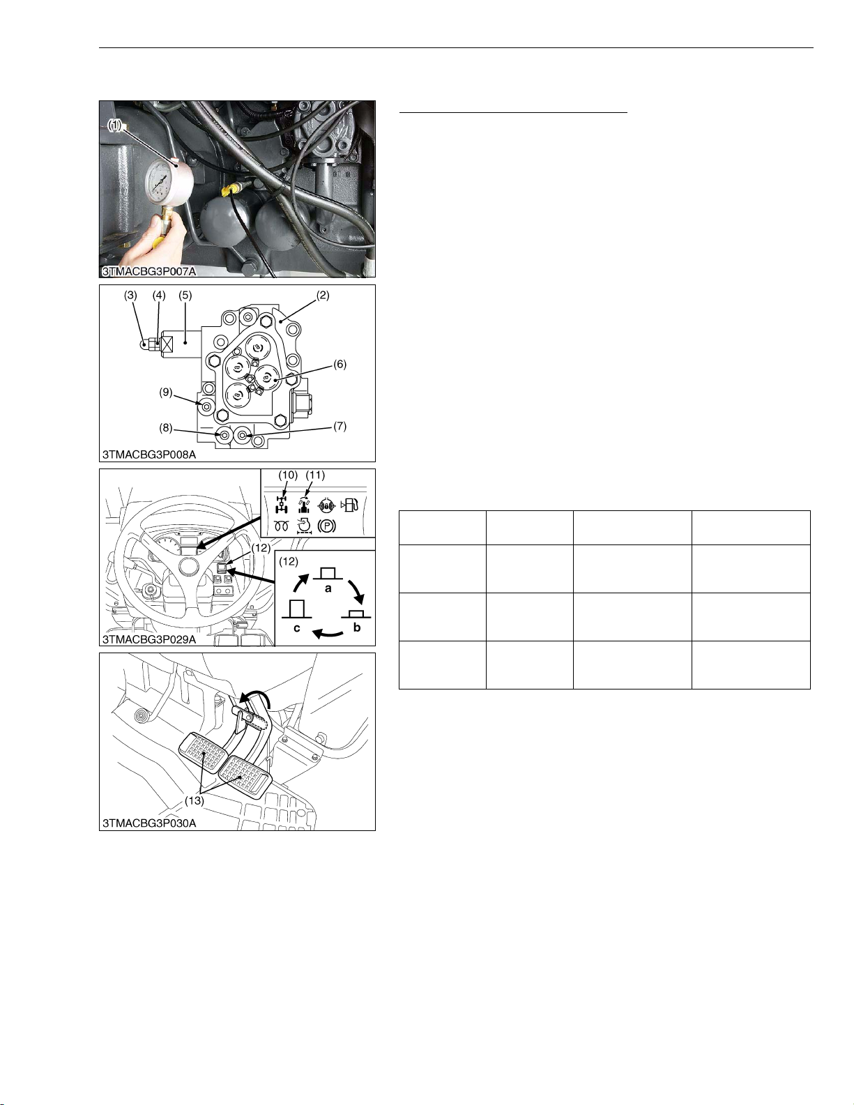
IMPORTANTQ
• Place the tractor on the flat surface and lock the both front
and rear wheels.
• Set the main shift lever and shuttle lever in Neutral position.
1. Place the disassembling stand under the transmission case.
2. Remove the rear wheels.
3. Place the disassembling stand under the rear axle case.
4. Place the disassembling stand under the front axle.
5. Remove the both R.H. and L.H. front wheels and place the
disassemble stand under the front axle for both side.
6. Remove the plug (R1/8) (7) (9) on the solenoid valve assembly
(2).
7. Assemble the adaptor (R1/8), threaded joint, cable and pressure
gauge (1).
8. Start the engine and measure the pressure of each port and each
4WD / Bi-speed turn switch (12) position as the table below.
9. Steer the steering wheel for the end of one side and measure the
oil pressure.
10.If only the pressure in the Bi-speed turn clutch engaged position
is low, check the hydraulic system.
11.If the measurement is not within the factory specifications,
measure the system pressure, and adjust the system pressure
with relief valve (5) if necessary.
4WD/Bi-speed
turn switch
4WD position Free
Bi-speed
position
2WD position
Brake Pedal 4WD port pressure
2.16 to 2.26 MPa
22 to 23 kgf/cm
312.91 to 327.14 psi
Free 0
Both pedals
are depressed
2.16 to 2.26 MPa
22 to 23 kgf/cm
312.91 to 327.14 psi
Condition
• Engine speed : Approx. 2600 min
−1
2
2
(rpm)
Bi-speed turn port
pressure
0
2.16 to 2.26 MPa
22 to 23 kgf/cm
312.91 to 327.14 psi
0
2
• Oil temperature : 45 to 55 °C
113 to 131 °F
(Reference)
• Turn the adjusting screw after removed cap nuts (3) and lock nut
(4).
• Turn the adjusting screw clockwise direction → Pressure
increase.
• Turn the adjusting screw counterclockwise → Pressure
decrease.
NOTEQ
• Plug thread size : R1/8
(1) Pressure Gauge
(2) Solenoid Valve Assembly
(3) Cap Nut
(4) Lock Nut
(5) Relief Valve (System Pressure)
(6) Solenoid Valve (Bi-Speed Turn
Check Port)
(7) Plug (Bi-Speed Turn Check Port)
(8) Plug (System Pressure Check Port)
(9) Plug (4WD Check Port)
(10) 4WD Indicator
(11) Bi-speed Turn Indicator
(12) 4WD / Bi-speed Turn Switch
(13) Brake Pedal
a : 4WD “ON”
b : Bi-speed Turn “ON”
c : 2WD (Switch OFF)
W1011273
L3-S3
Page 31
M9540Low Profile, WSM
KiSC issued 09, 2008 A
3. DISASSEMBLING AND ASSEMBLING
[1] HYDRAULIC SHUTTLE VALVE
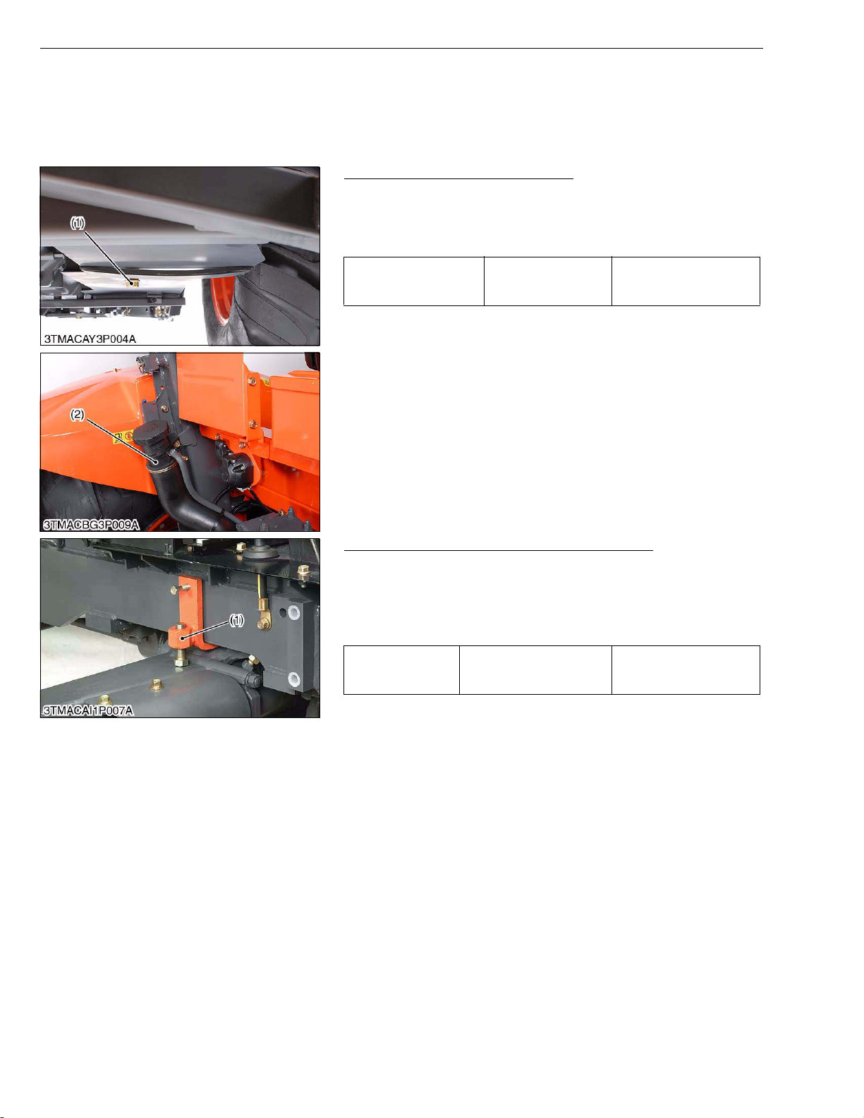
(1) Removing Fuel Tank
Draining Fuel and Fuel Filling Port
1. Place oil pans under the fuel tank.
2. Remove the drain plug (1) and drain the fuel.
3. Reinstall the drain plug (1) to the fuel tank.
4. Unscrew the fuel filling port fixing screw.
Fuel tank Capacity
(1) Fuel Tank (1) Fuel Filling Port
TRANSMISSION
90 L
23.8 U.S.gals
19.8 Imp.gals
W1038723
Rear Wheel and Front Axle Rocking Restrictor
1. Place the disassembling stand under the transmission case.
2. Install the front axle rocking restrictor (1). (Refer to “8. SPECIAL
TOOLS” at “G.GENERAL” section.)
3. Remove the rear wheel.
(When reassembling)
343.2 to 393.3 N·m
Tightening torque Rear wheel mounting nut
(1) Front Axle Rocking Restrictor
35.0 to 40.1 kgf·m
253.2 to 290.0 lbf·ft
W1041327
L3-S4
Page 32
M9540Low Profile, WSM
KiSC issued 09, 2008 A
TRANSMISSION
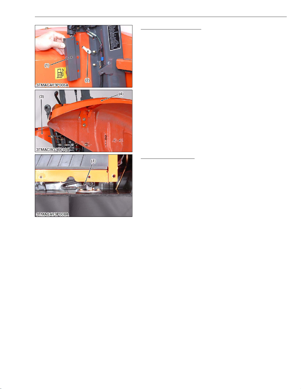
Fender and Auxiliary Step
1. Remove the harness cover (1) and disconnect the 4P connector
(2).
2. Remove the fender (3), (4) and auxiliary step.
(When reassembling)
• Be sure to assemble the fender to the original height.
(1) Harness Cover
(2) 4P Connector
(3) Fender L.H.
(4) Fender R.H.
W1011951
Fuel Sensor Connector
1. Remove the fuel sensor 2P connector (1).
(When reassembling)
• Be sure to connect the fuel sensor connector.
(1) Fuel Sensor 2P Connector
W1039151
L3-S5
Page 33
M9540Low Profile, WSM
KiSC issued 09, 2008 A
TRANSMISSION
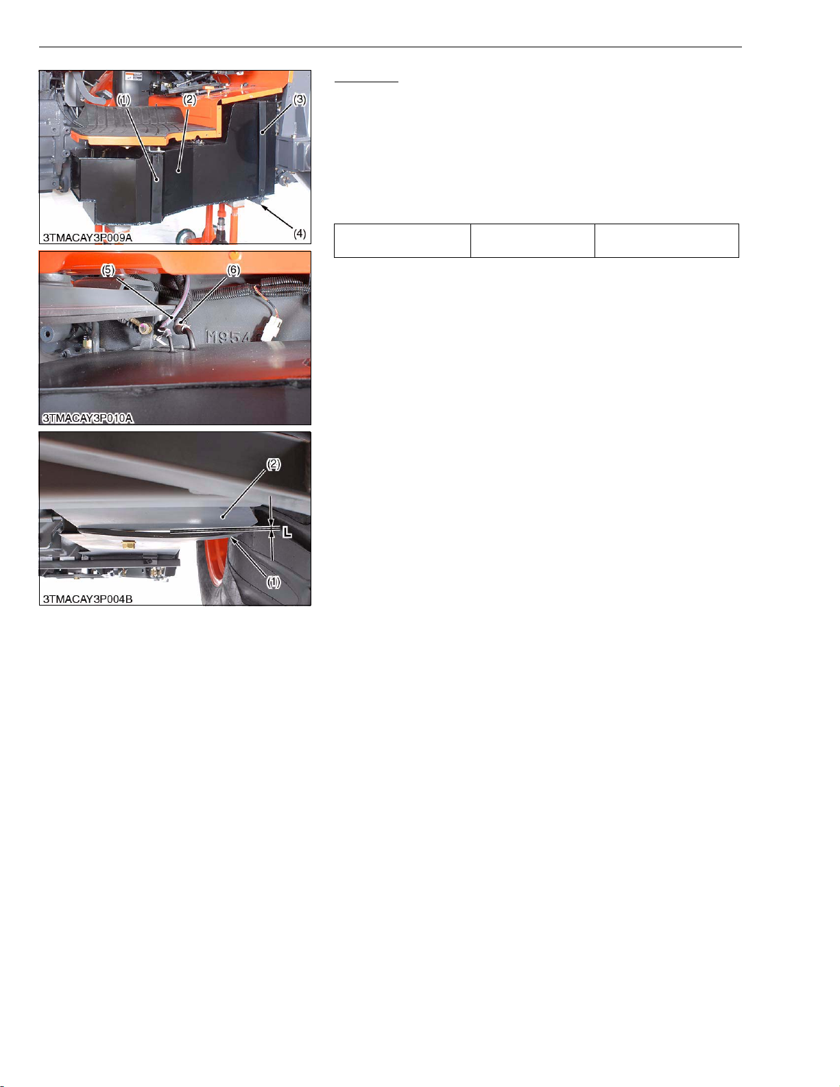
Fuel Tank
1. Place the disassembling stand under the fuel tank (2).
2. Remove the fuel tank band (1) and (3).
3. Remove the fuel tank stay (4).
4. Lower the fuel tank (2) to disconnect the fuel hose (5) and (6).
5. Remove the fuel tank (2).
(When reassembling)
• Tighten the fuel tank band so that the clearance L between the
fuel tank and fuel tank band become as follow.
Clearance between fuel
tank and fuel tank band
Factory spec.
2.0 to 4.0 mm
0.079 to 0.16 in.
(1) Fuel Tank Band
(2) Fuel Tank
(3) Fuel Tank Band
(4) Fuel Tank Stay
(5) Fuel Hose (Return)
(6) Fuel Hose
L : Clearance
W1012313
L3-S6
Page 34
M9540Low Profile, WSM
KiSC issued 09, 2008 A
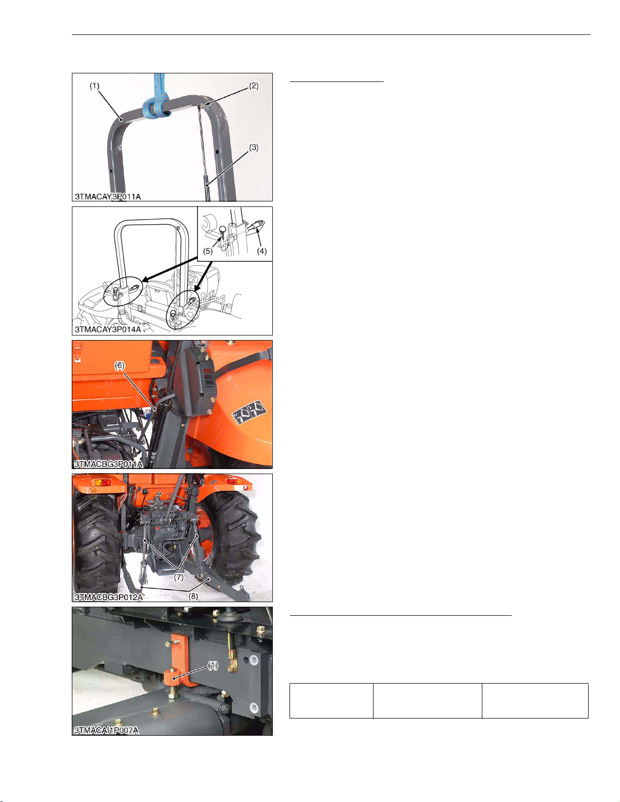
[2] ROPS
ROPS Upper Frame
1. Hook the upper frame (1).
2. Remove the damper mounting nut (2).
3. Remove the lunch pin (5) and set bolt (4).
4. Remove the upper frame (1) using a hoist.
5. Remove the external position control rod (6).
6. Remove the lift rod (7) and lower link (8).
(1) Upper Frame
(2) Nut
(3) Damper
(4) Set Bolt
(5) Lynch Pin
(6) External Position Control Rod
(7) Lift Rod
(8) Lower Link
TRANSMISSION
W1012812
Rear Wheel and Front Axle Rocking Restrictor
1. Place the disassembling stand under the transmission case.
2. Install the front axle rocking restrictor (1). (Refer to “8. SPECIAL
TOOLS” at “G.GENERAL” section.)
3. Remove the rear wheel.
(When reassembling)
343.2 to 393.3 N·m
Tightening torque Rear wheel mounting nut
(1) Front Axle Rocking Restrictor
35.0 to 40.1 kgf·m
253.2 to 290.0 lbf·ft
W1012997
L3-S7
Page 35
M9540Low Profile, WSM
KiSC issued 09, 2008 A
TRANSMISSION
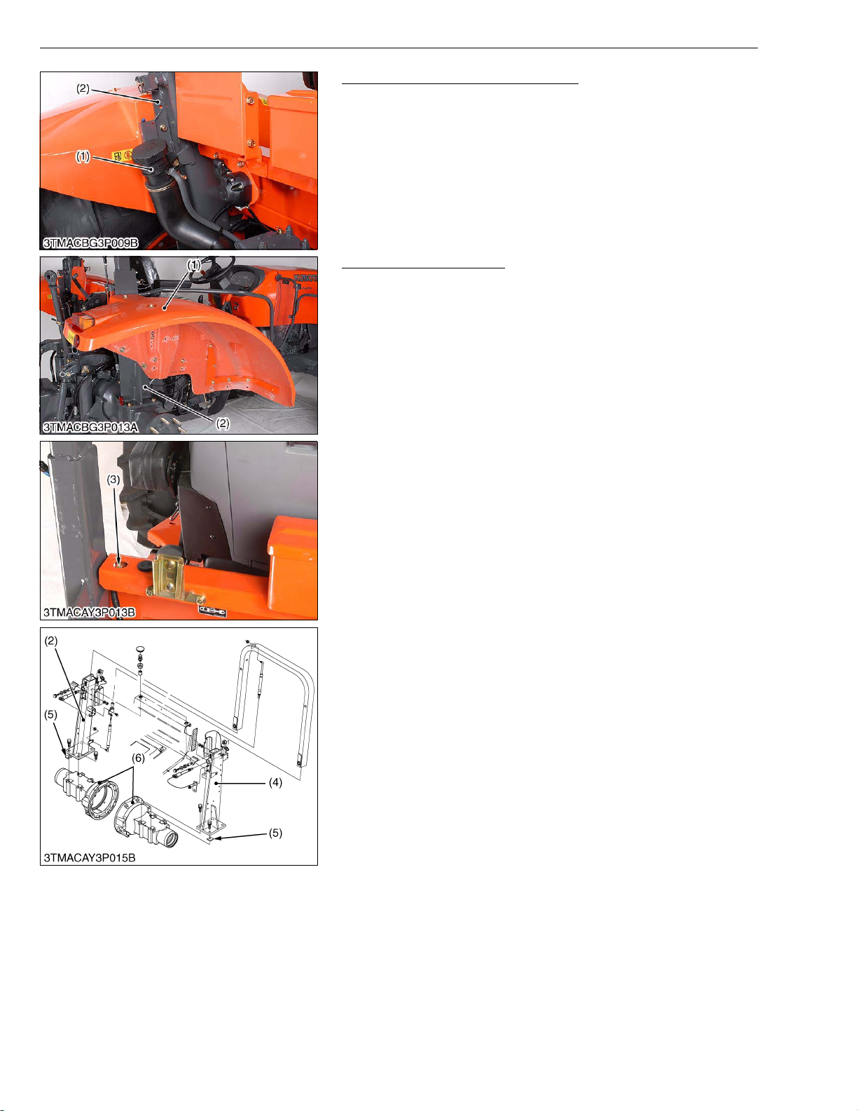
Fuel Filling Port and Harness Cover
1. Unscrew the fuel filling port (1) fixing screw.
2. Remove the harness cover (2) both L.H. and R.H. side.
(1) Fuel Filling Port (2) Harness Cover
W1013126
Fender and ROPS Under
1. Remove the both fenders (1).
2. Remove the screw (3) for both side then take out the ROPS
under L.H. (4) and R.H. (2).
(When reassembling)
• Be sure to assemble the fender to the original height.
• If the adjusting shim (5) uses between the ROPS under and rear
axle case, assemble the shim to the original position.
• Be sure to check the ROPS slides smoothly, after assembling. If
ROPS does not slide smoothly, adjust with shim (5).
(1) Fender L.H.
(2) ROPS Under R.H.
(3) Screw
(4) ROPS Under L.H.
(5) Shim
(6) Rear Axle Case
W1013188
L3-S8
Page 36
M9540Low Profile, WSM
KiSC issued 09, 2008 A
[3] 4WD CLUTCH PACK AND BI-SPEED TURN CLUTCH PACK
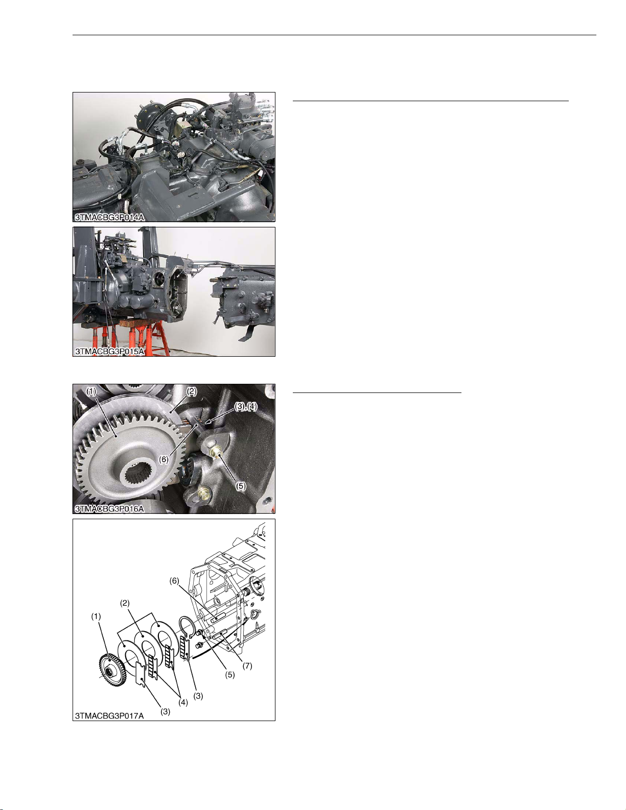
(1) Separating Transmission Case and Clutch Housing Case
Separating Transmission Case and Clutch Housing Case
1. Remove the hydraulic hoses and hydraulic brake pipes.
2. Refer to the “Disassembling and Assembling” section at “3.
TRANSMISSION”.
TRANSMISSION
W1014059
(2) 4WD Clutch Pack and Bi-Speed Turn Clutch Pack
Parking Brake Disc and Steel Plate
1. Remove the stopper screw (5) and upper pin (6).
2. Remove the disc (3) and (4).
3. Remove the 47T gear (1) with steel plates (2).
(When reassembling)
• Be sure to assemble the disc (3) and (4) to the original position
as shown fig.
(1) 47T Gear
(2) Steel Plate
(3) Disc (5.1 mm, 0.20 in.)
(4) Disc (2.8 mm, 0.11 in.)
(5) Stopper Screw
(6) Upper Pin
(7) Lower Pin
W1014172
L3-S9
Page 37
M9540Low Profile, WSM
KiSC issued 09, 2008 A
TRANSMISSION
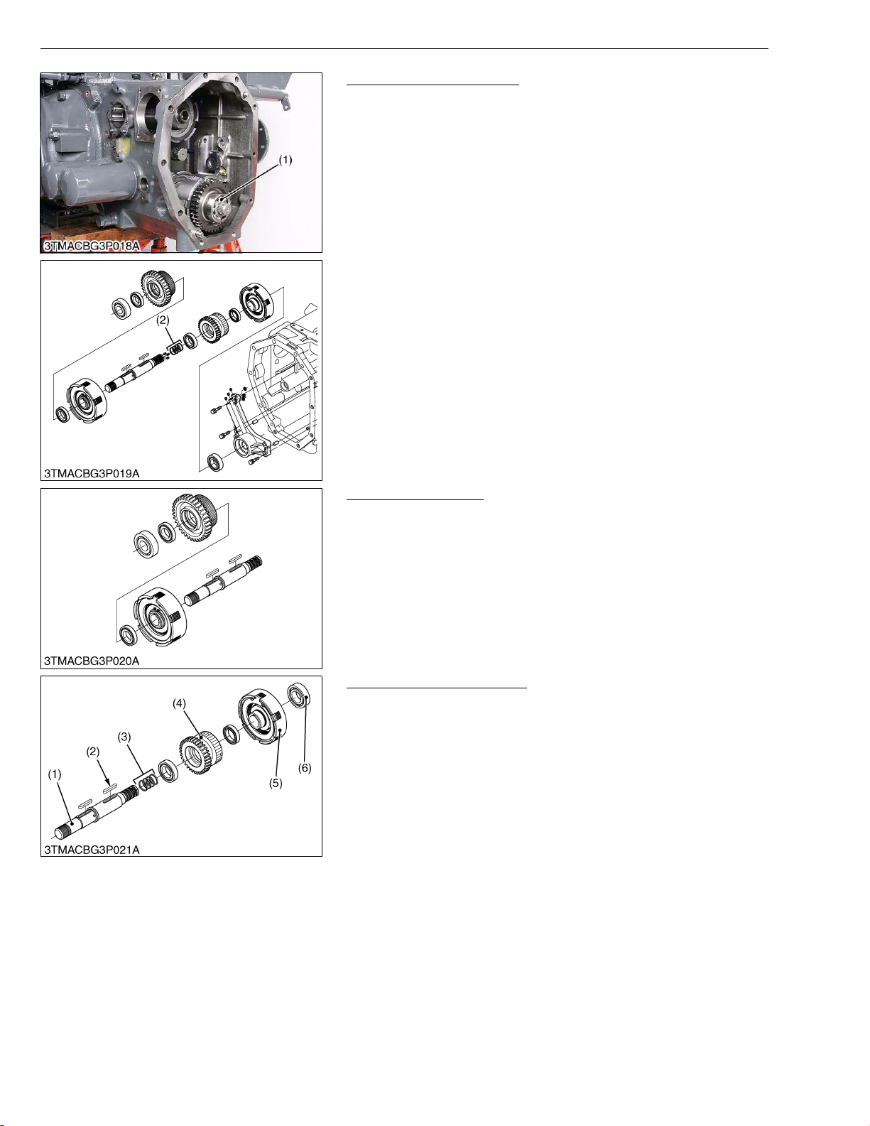
Hydraulic Pack Assembly
1. Remove the hydraulic pack assembly (1).
(When reassembling)
• Replace the seal rings (2) with new one, if they have deformed or
any damages.
• Apply grease to the seal ring (2).
(1) Hydraulic Pack Assembly (2) Seal Ring
W1014413
4WD Hydraulic Pack
1. Refer to the “DISASSEMBLING AND ASSEMBLING” at “3.
TRANSMISSION”.
W1014706
Bi-speed Turn Clutch Pack
1. Remove the seal rings (3) and bearing (6) from the 4WD shaft
(1).
2. Remove the Bi-speed turn clutch pack (5).
3. Remove the 33T gear (4), after removing the key (2).
W1014782
L3-S10
Page 38
M9540Low Profile, WSM
KiSC issued 09, 2008 A
TRANSMISSION
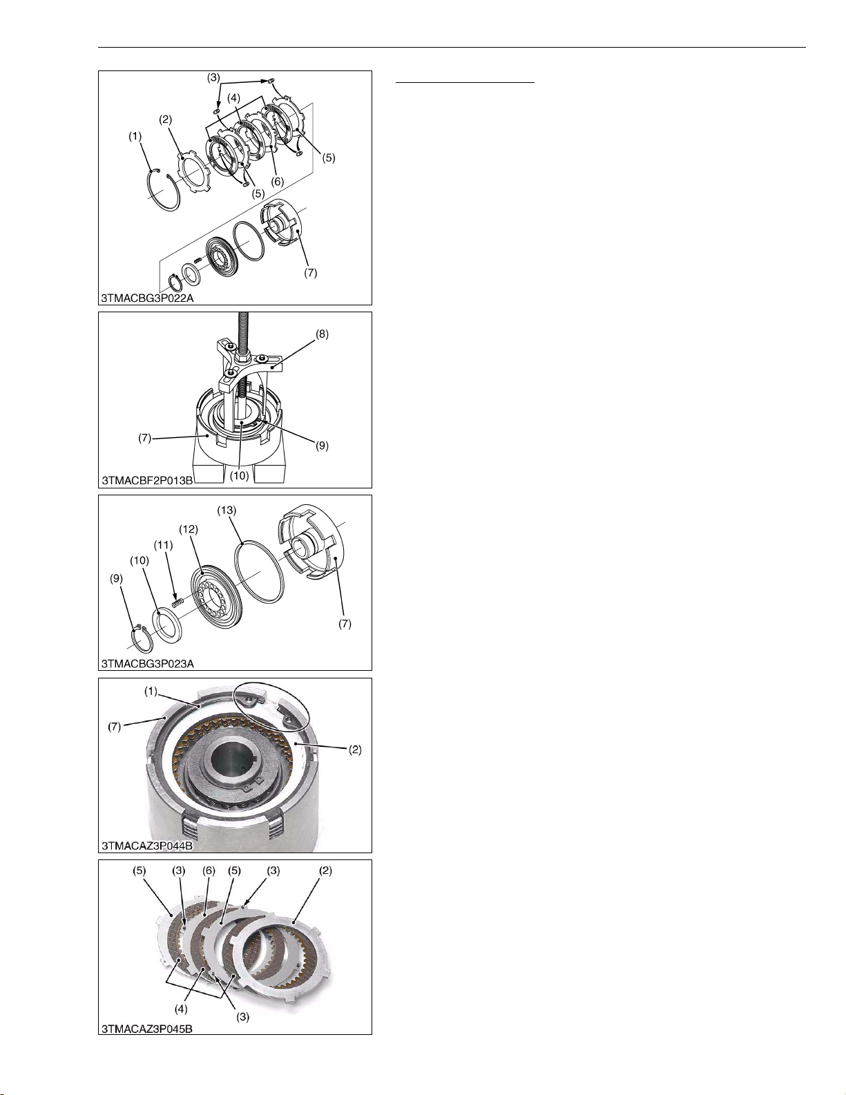
Bi-speed Turn Piston
1. Remove the internal circlip (1).
2. Take out the pressure plate (2), discs (4), steel plate.
3. Press the washer (10) lightly, using the clutch compressor (8)
(refer to “4. SPECIAL TOOLS” at “NG. GENERAL” section), and
remove the external circlip (9).
4. Remove the springs (10).
5. Draw out the Bi-speed turn piston (11) using an air pressure.
NOTEQ
• 15 springs for Bi-speed turn piston.
• 3 discs and 3 steel plates for Bi-speed turn clutch side.
(When reassembling)
• Apply oil to the D-rings (13) and install the Bi-speed turn piston
(12).
• Install the clutch discs (4) and steel plate (5), (6) mutually.
• Apply enough transmission fluid to the discs (4).
• Do not confuse the two types of steel plates.
The steel plate with rubbers (5) and without rubbers (6).
• Do not confuse the pressure plates (2) and steel plate (5) and (6).
The pressure plate (2) is thicker than the steel plate.
• Put the rubber positions that consecutively set up, to not come in
touch with each rubber (3) directly as shown photo.
• When installing the internal circlip (1) to the clutch case (7), align
its split portion to the notched portion of clutch case (7) as shown
in photo.
(1) Internal Circlip
(2) Pressure Plate
(3) Rubber
(4) Disc
(5) Steel Plate with Rubber
(6) Steel Plate without Rubber
(7) Clutch Case
(8) Clutch Compressor
(9) External Circlip
(10) XXXXXX
(11) Spring
(12) Bi-speed Turn Piston
(13) D-ring
W1014896
L3-S11
Page 39
M9540Low Profile, WSM
KiSC issued 09, 2008 A
4. SERVICING
[1] 4WD / BI-SPEED TURN CLUTCH PACK
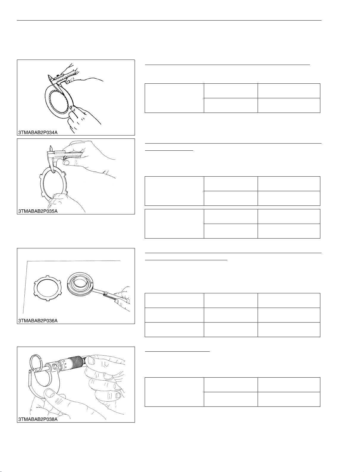
Clutch Disc Wear (Both 4WD Side and Bi-speed Turn Side)
1. Measure the thickness of clutch disc with vernier calipers.
2. If the thickness is less than the allowable limit, replace it.
Thickness of clutch disc
Steel Plate and Pressure Plate Wear (Both 4WD Side and Bispeed Turn Side)
1. Measure the thickness of steel plate and pressure plate with
vernier calipers.
2. If the thickness is less than the allowable limit, replace it.
Thickness of steel plate
Factory spec.
Allowable limit
Factory spec.
Allowable limit
TRANSMISSION
2.1 to 2.3 mm
0.083 to 0.090 in.
1.9 mm
0.075 in.
W1016467
1.67 to 1.83 mm
0.0658 to 0.0720 in.
1.3 mm
0.051 in.
4.42 to 4.58 mm
0.174 to 0.180 in.
3.7 mm
0.15 in.
W1016583
Thickness of pressure
plate
Factory spec.
Allowable limit
Flatness of Piston, Steel Plate and Pressure Plate (Both 4WD
Side and Bi-speed Turn Side)
1. Place the part on a surface plate and check it unable to insert a
feeler gauge (allowable limit size) underneath it (at lease four
points).
2. If the gauge can be inserted, replace it.
Flatness of piston Allowable limit
Flatness of steel plate Allowable limit
Flatness of pressure
plate
Allowable limit
0.15 mm
0.006 in.
0.40 mm
0.016 in.
0.30 mm
0.012 in.
W1016731
Thickness of Seal Ring
1. Measure the thickness of seal rings (1) with an outside
micrometer.
2. If the measurement is less than the allowable limit, replace it.
Factory spec.
Thickness of seal ring
Allowable limit
2.39 to 2.44 mm
0.0941 to 0.0960 in.
2.0 mm
0.079 in.
(1) Seal Ring
W1016857
L3-S12
Page 40

L6 FRONT AXLE
KiSC issued 09, 2008 A
Page 41

MECHANISM
KiSC issued 09, 2008 A
CONTENTS
1. STRUCTURE ............................................................................................... L6-M1
[1] 4 WHEEL DRIVE ................................................................................. L6-M1
Page 42
M9540Low Profile, WSM
KiSC issued 09, 2008 A
FRONT AXLE
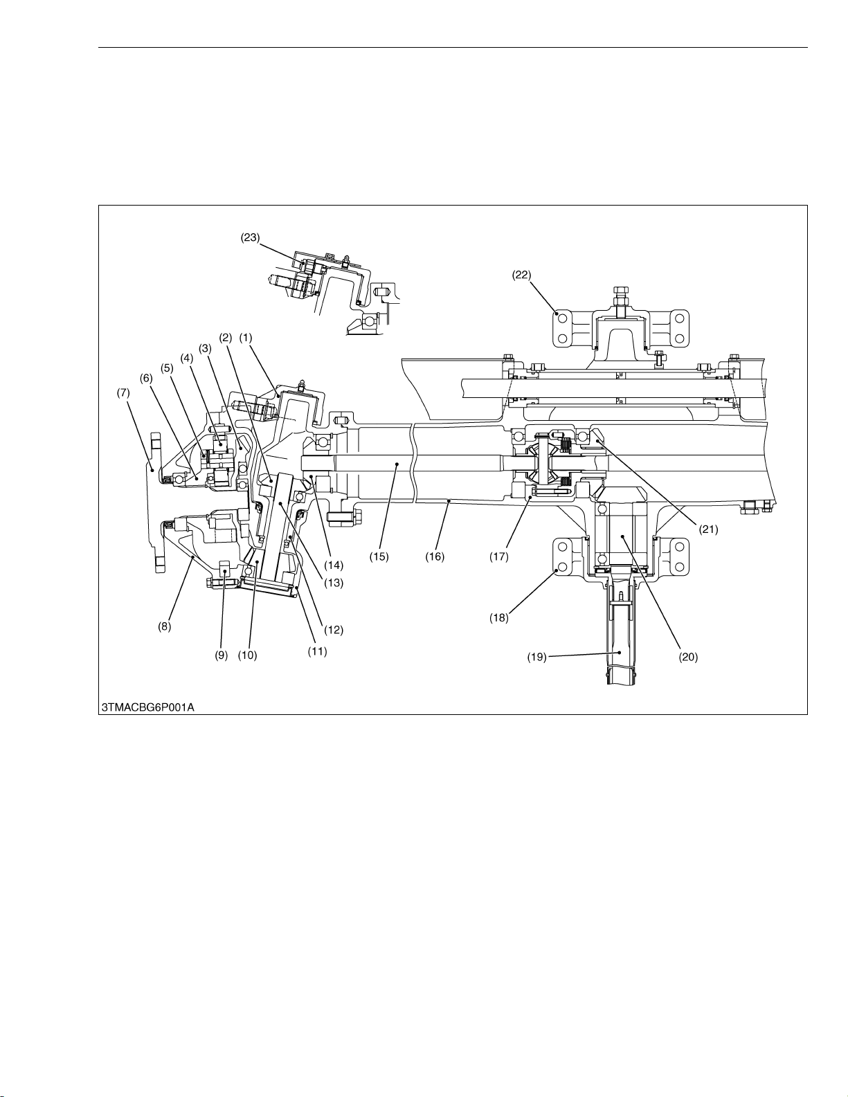
1. STRUCTURE
The front axle supports the front of tractor and facilitates steering.
The four-wheel drive axle has powered front wheels.
NOTEQ
• Refer to “6. FRONT AXLE” section in the workshop manual of tractor mechanism (Code No. 9Y021-18200).
[1] 4 WHEEL DRIVE
(1) Front Axle Case Support
(2) 18T Bevel Gear
(3) 41T Bevel Gear
(4) 23T Planetary Gear
(5) Planetary Gear Pin
(6) Planetary Gear Support
(7) Front Axle
(8) Front Axle Case Cover
(9) 62T Internal Gear
(10) 15T Bevel Gear
(11) Front Axle Case
(12) Bevel Gear Case
(13) Bevel Gear Shaft
(14) 17T Bevel Gear
(15) Differential Yoke Shaft
(16) Front Differential Case
(17) Differential Gear Assembly
(LSD)
(18) Bracket (Rear)
L6-M1
(19) Propeller Shaft
(20) 17T Bevel Pinion Shaft
(21) 23T Bevel Gear
(22) Bracket (Front)
(23) Turning Angle Inspection
Switch
Page 43

SERVICING
KiSC issued 09, 2008 A
CONTENTS
1. SERVICING SPECIFICATIONS ..................................................................L6-S1
2. DISASSEMBLING AND ASSEMBLING ......................................................L6-S2
[1] DISASSEMBLING AND ASSEMBLING................................................L6-S2
Page 44

M9540Low Profile, WSM
KiSC issued 09, 2008 A
1. SERVICING SPECIFICATIONS
Item Factory Specification Allowable Limit
Turning angle Inspection Switch Operating Angle 0.53 to 0.59 rad
30 to 34 degree
FRONT AXLE
–
W1013874
L6-S1
Page 45
M9540Low Profile, WSM
KiSC issued 09, 2008 A
2. DISASSEMBLING AND ASSEMBLING
[1] DISASSEMBLING AND ASSEMBLING
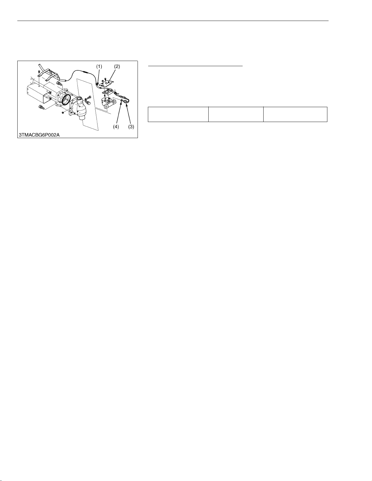
Turning Angle Inspection Switch
1. Remove the cover (2).
2. Remove the turning angle inspection switch (3).
(When reassembling)
• Adjust the turning angle inspection switch operating angle with
adjusting shim.
Turning angle inspection
switch operating angle
•Shim
0.5 mm (0.02 in.) : 3A481-40470
1.0 mm (0.039 in.) : 3A481-40460
NOTEQ
• Remove the turning angle inspection switch to execute the
“Separating Front Axle” and “Disassembling Front Axle”.
(1) Wire Harness
(2) Cover
Factory spec.
FRONT AXLE
0.53 to 0.59 rad
30 to 34 degree
(3) Turning Angle Inspection Switch
(4) Adjusting Shim
W1010690
L6-S2
Page 46

L8 HYDRAULIC SYSTEM
KiSC issued 09, 2008 A
Page 47

MECHANISM
KiSC issued 09, 2008 A
CONTENTS
1. HYDRAULIC CIRCUIT ................................................................................ L8-M1
[1] TOTAL HYDRAULIC CIRCUIT ............................................................ L8-M1
(1) F18/R18 Speed Transmission Model............................................... L8-M1
Page 48
M9540Low Profile, WSM
KiSC issued 09, 2008 A
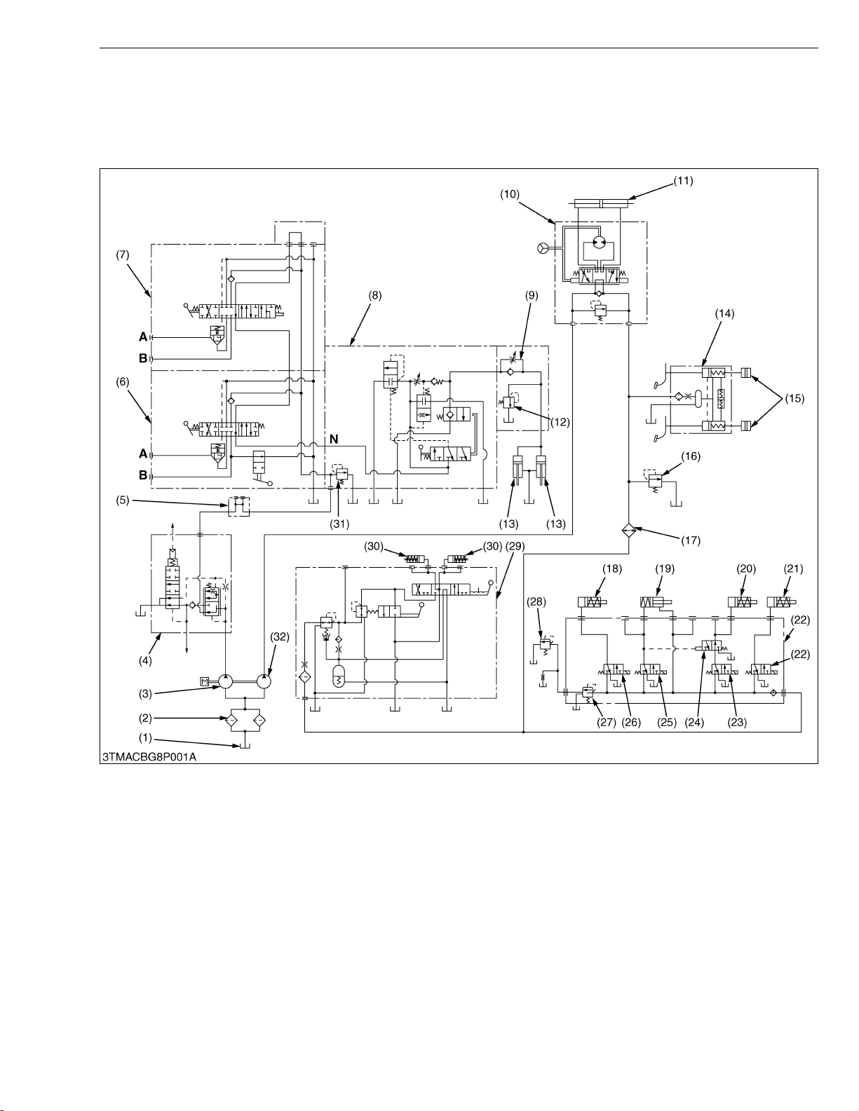
1. HYDRAULIC CIRCUIT
[1] TOTAL HYDRAULIC CIRCUIT
(1) F18/R18 Speed Transmission Model
HYDRAULIC SYSTEM
(1) Oil Tank (Transmission Case)
(2) Hydraulic Oil Filter Cartridge
(3) Hydraulic Pump (for 3-point)
(4) Trailer Brake (Option)
(5) Hydraulic Outlet
(6) Auxiliary Control Valve (S/D)
(7) Auxiliary Control Valve (SCD)
(8) Control Valve (for 3-point)
(9) Lowering Speed Adjusting
Val ve
(10) Power Steering Controller
(11) Steering Cylinder
(12) Cylinder Safety Valve
(13) Exterior Hydraulic Cylinder
(14) Brake Master Cylinder
(15) Brake Piston
(16) Oil Cooler Relief Valve
(17) Oil Cooler
(18) PTO Clutch Pack
(19) 4WD Clutch Pack
(20) Bi-speed Turn Clutch Pack
(21) Rear Differential Lock Clutch
Pack
(22) Solenoid Valve Assembly
(23) Solenoid Valve (Bi-speed
Turn)
(24) Solenoid Valve (Priority)
(25) Solenoid Valve (4WD)
(26) Solenoid Valve (PTO)
(27) Relief Valve (for System)
L8-M1
(28) Relief Valve (for Lubricating
Line)
(29) Shuttle Valve
(30) Shuttle Clutch Pack
(31) Relief Valve for 3-point
(32) Hydraulic Pump (Power
Steering, PTO Clutch, 4WD
Clutch and Shuttle Clutch)
A : To Implement Cylinder
B : To Implement Cylinder
N : N Port
Page 49

SERVICING
KiSC issued 09, 2008 A
CONTENTS
1. TROUBLESHOOTING ..................................................................................L8-S1
2. SERVICING SPECIFICATIONS ..................................................................L8-S2
3. CHECKING, DISASSEMBLING AND SERVICING....................................L8-S3
[1] CHECKING AND ADJUSTING .............................................................L8-S3
(1) Position and Draft Control Linkage ...................................................L8-S3
Page 50
M9540Low Profile, WSM
KiSC issued 09, 2008 A
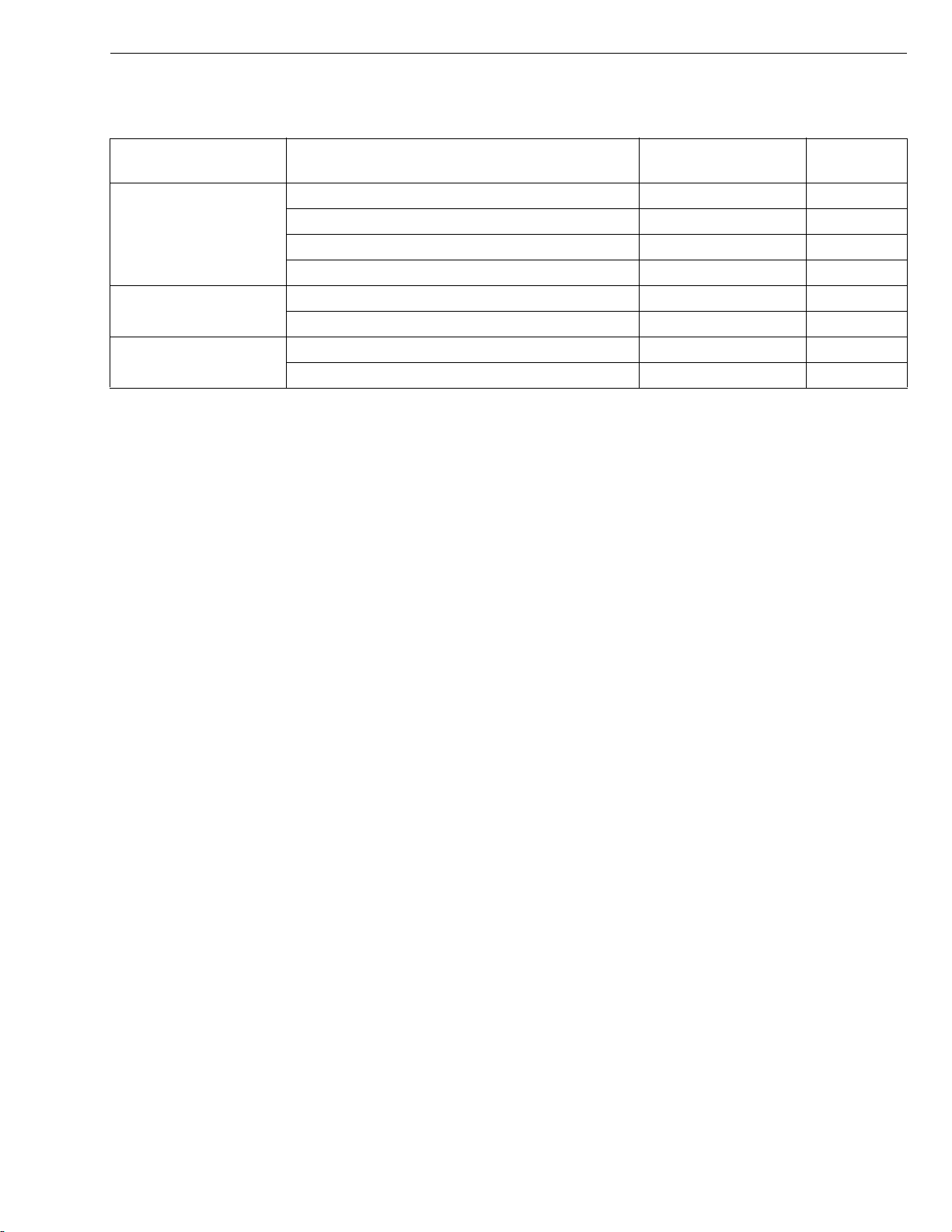
1. TROUBLESHOOTING
BI-SPEED TURN
Symptom Probable Cause Solution
Bi-Speed Turn Clutch
Slip
Bi-Speed Turn Does
Not Rotate
Operating Pressure
Is Low
Operating pressure is low Adjust L3-S3
Bi-Speed turn solenoid Repair or replace L9-S11
Clutch disc or drive plate excessively worn Replace L3-S10, 12
Deformation of piston Replace L3-S10
Bi-Speed turn clutch malfunctioning Repair or replace L3-S10
4WD propeller shaft coupling disengaged Engage –
Transmission oil improper or insufficient Replenish or change G-9
Relief valve malfunctioning Adjust or replace L3-S3
HYDRAULIC SYSTEM
Reference
Page
W1013580
L8-S1
Page 51

M9540Low Profile, WSM
KiSC issued 09, 2008 A
2. SERVICING SPECIFICATIONS
POSITION AND DRAFT CONTROL LINKAGE
Item Factory Specification Allowable Limit
Position Control Rod (ROPS) Length Approx. 160 mm
6.30 in.
Draft Control Rod (ROPS) Length Approx. 144 mm
5.67 in.
HYDRAULIC SYSTEM
–
–
W1013874
L8-S2
Page 52
M9540Low Profile, WSM
KiSC issued 09, 2008 A
HYDRAULIC SYSTEM
3. CHECKING, DISASSEMBLING AND SERVICING
[1] CHECKING AND ADJUSTING
(1) Position and Draft Control Linkage
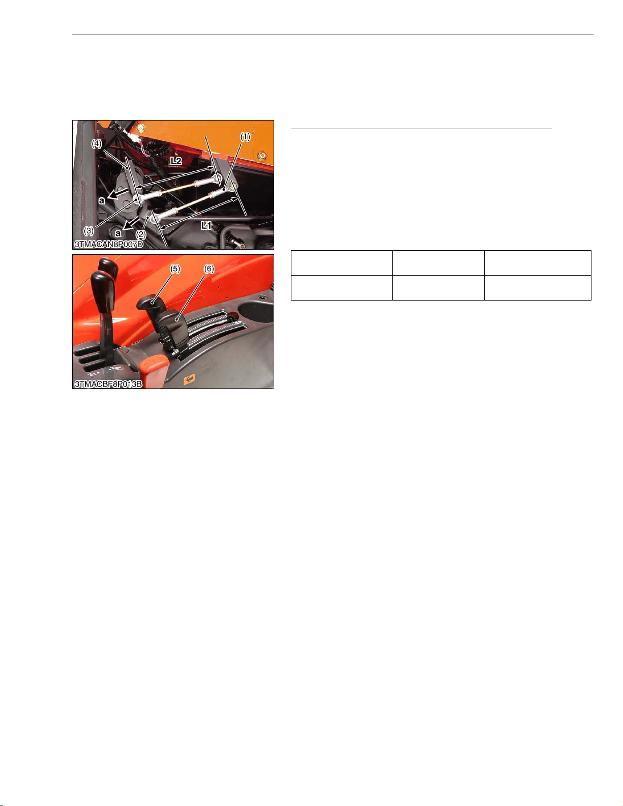
Adjusting Position Control Rod and Draft Control Rod
1. Be sure to adjust the position control rod (1) length (L1) and draft
control rod (3) length (L2).
IMPORTANTQ
• Each draft control lever and position control lever should
contact with lever guide lowest position when operate the
position lever 1 (2) and draft lever 1 (4) to end of direction (a).
If not, adjust the position control rod (1) length (L1) and/or
draft control rod (3) length (L2).
[ROPS Model]
Position control rod
length (L1)
Draft control rod length
(L2)
(1) Position Control Rod
(2) Position Lever 1
(3) Draft Control Rod
(4) Draft Lever 1
(5) Position Control Lever
(6) Draft Control Lever
Factory spec.
Factory spec.
L1 :Length of Position Control Rod
L2 :Length of Draft Control Rod
a : Direction for Lower
Approx. 160 mm
6.30 in.
Approx. 144 mm
5.67 in.
W1011113
L8-S3
Page 53

L9 ELECTRICAL SYSTEM
KiSC issued 09, 2008 A
Page 54

MECHANISM
KiSC issued 09, 2008 A
CONTENTS
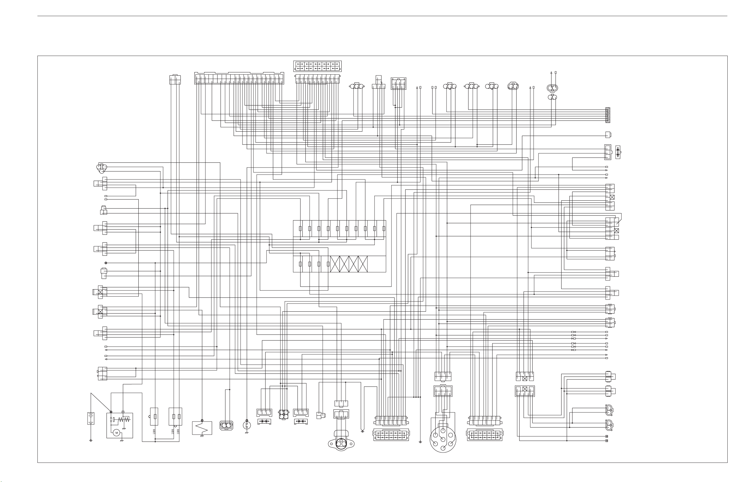
1. WIRING DIAGRAM ..................................................................................... L9-M1
[1] MAIN HARNESS................................................................................... L9-M1
2. ELECTRICAL CIRCUIT DETAILED CHART............................................. L9-M2
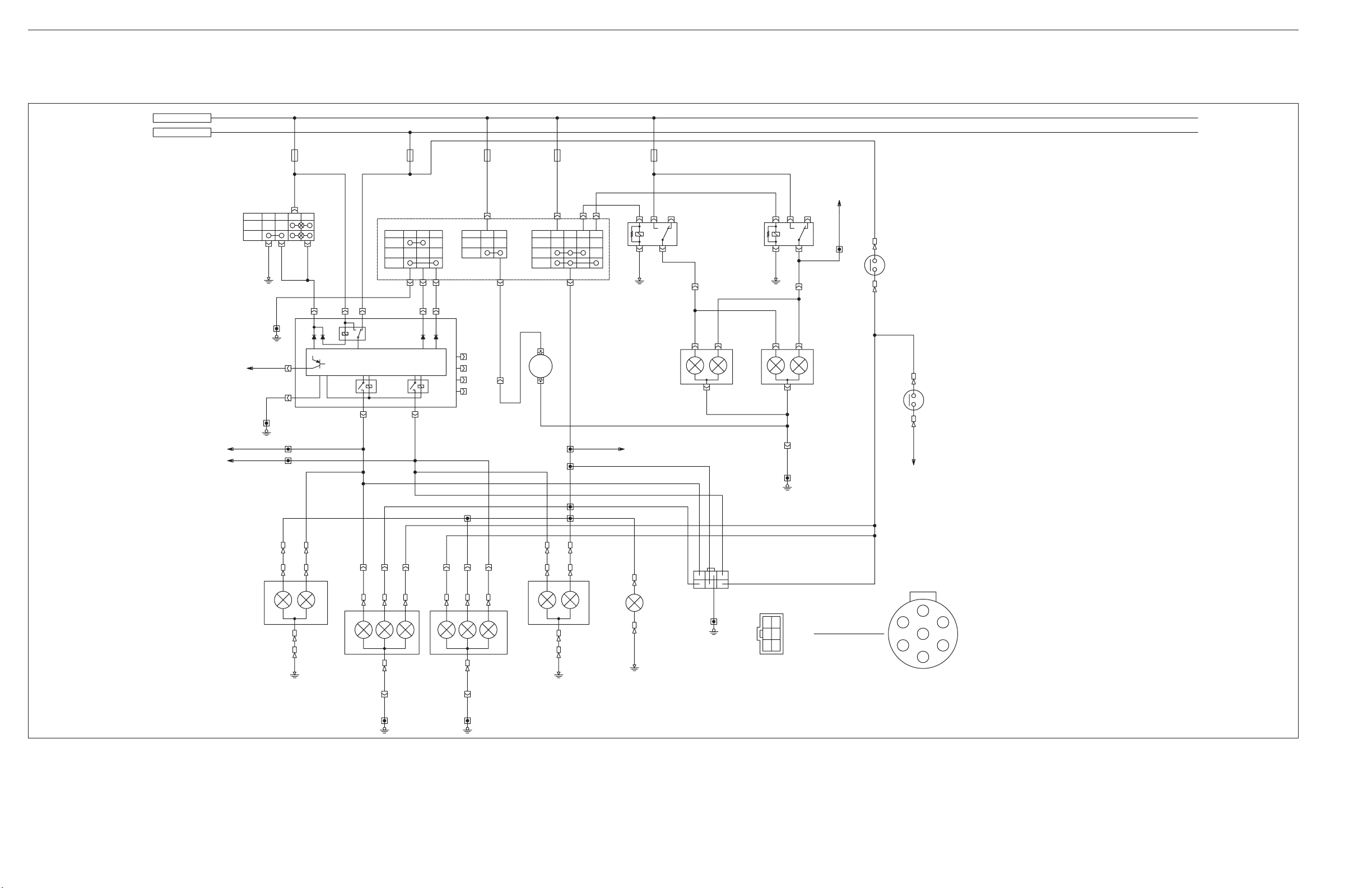
[1] LIGHTING SYSTEM ............................................................................. L9-M2
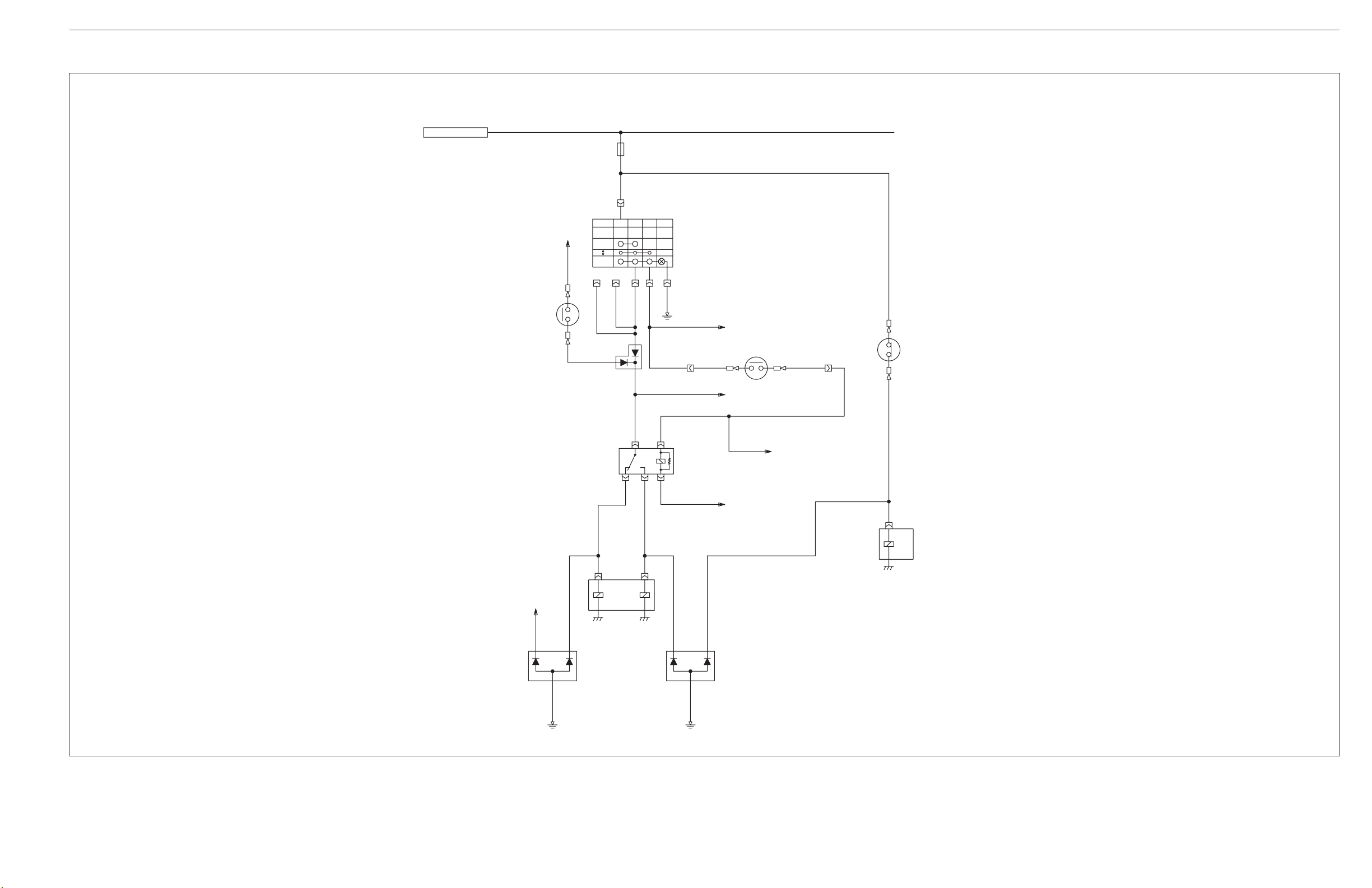
[2] 4WD / BI-SPEED TURN (T/M CONTROL) SYSTEM ........................ L9-M3
[3] INSTRUMENT PANEL BOARD (METER PANEL) ............................ L9-M4
[4] WIRING COLOR ................................................................................... L9-M5
3. INSTRUMENT PANEL ................................................................................ L9-M6
[1] INDICATION ITEMS OF METER PANEL .......................................... L9-M6
Page 55
M9540Low Profile, WSM
KiSC issued 09, 2008 A
1. WIRING DIAGRAM
[1] MAIN HARNESS
0.50 L/R
0.50 P/W
60 B/Y60 B/Y
23
35
2
3
1
2
3
1
ac
//
de
1
2
4135
/
2
4135
2
4
1
M6
R
L
5
5
2
4135
0.50 R/W
0.50 B
0.50 B/Y
0.85 B/L
0.50 P/W
0.85 B/L
0.85 B/Y
0.85 R
0.85 B
0.50 BR/R
0.50 R/W
0.85 Y/R
0.50 R/W
0.50 B
3.00 R/B
0.85 Y/R
5.00 W
0.50 R/W
0.50 W/G
0.50 B
3.00 R/B
3.00 B/W
0.85 B/Y
0.50 SB
5.00 R
5.00 W
0.50 R/W
0.50 B
3.00 R/G
3.00 R/B
0.50 R/W
0.85 R
0.85 B
0.85 R/L
0.85 B
0.85 W/R
0.85 R
0.85 W/R
0.50 B
5.00 W
M8
SB
M
Starter Motor
3.00 B/W
PTO Switch
PTO Safety Relay
T/M Neutral Switch
AUX Power Connector
Engine Stop Relay
Key Stop Relay
Alternator
Starter Relay
Heater Relay
Working Light Relay
Working Light R.H.
Working Light L.H.
Front Side
Working Light Switch
Battery
3TMACBG9P004A
5.00 W
50A
S.B.FUSE
Main Key
Switch
ST M
B/
2.00 B/W
3.00 R
3.00 R/W
3.00 R
3.00 R/B
30A
40A
S.B.FUSE BOX
Meter Panel
0.50 R/B
0.50 L
0.50 LG/B
0.50 R
0.50 GY/B
Engine
Oil Pressure
Switch
0.50 W
0.50 W
M4
0.50 W/G
0.50 P/W
14
0.50 L/G
0.50 Y/L
0.50 G/B
0.50 P/W
0.50 B/R
0.50 GY/B
Diode
(PTO/DT Sol)
0.50 R/G
0.50 W/R
0.50 B
123
0.50 V/W
0.50 R/B
0.50 Y
0.50 BR/W
////
1 3 10 11 12 13 15 16 17 18 19 20
/////
2
//2827
21 24 29 32 33 34 36 37 38 40
0.50 G/W
0.50 SB
0.50 BR/R
0.50 G/OR
5.00 R
M6
26 30 31
0.50 P
0.50 B/Y
0.50 G/W
2.00 R/Y
0.50 BR/Y
0.50 W/G
2.00 R/Y
12
Intake Air
Heater
Key Stop
Solenoid
L9-M1
0.50 B/W
0.50 B
3.00 R/G
3.00 R/W
3.00 R
2.00 B/W2.00 R/Y
3.00 W/R
3.00 R
0.50 L/R
0.50 BR/W
0.50 P/L
B
DL
PTO DT
PTO/DT
Valve
Work Light R
Horn
0.85 GY/B
Diode
(PTO/DT Sol)
0.50 V/W
0.50 R/B
0.50 P/L
0.85 V/W
0.50 R/B
0.50 G/B
0.85 R
15A
Work Light L
10A
Head Light
0.85 LG
0.50 B
0.50 L/R
123
0.50 G/B
0.50 B/W
0.50 B/W
0.50 P/W
0.85 R/L
15A
Alternator,
15A
Aux Socket
0.85 LG/R
Seat
Compressor
J/C
0.50 P
0.50 P
0.50 P/W
0.50 BR
0.85 BR/Y
0.50 BR/Y
0.50 R/W
5A
Meter Panel
Heater
Engine,PTO,
25A
Starter Relay
2.00 W/R
0.85 R
0.85 B
/
AUX. Power Socket
0.50 B/R
0.50 B/Y
0.50 R/G
5A
Turn Signal,
5A
0.50 B/Y
0.50 W
0.50 W
0.50 B/Y
0.85 R/Y
10A
Stop Lamp
0.85 R
2.00 W/R
123
123
2.00 W/R
0.85 R/W
Display Mode
Select Switch
0.85 R
15A
Auxiliary
Power
T/M Control
2.00 B
2.00 B
312
0.50 R/G
0.50 L
0.50 R/G
10A
Ground
(Rear)
0.50 LG/B
(Backup)
Meter
2.00 B
2.00 B
0.50 R/B
5A
M8
DT/Bi-Speed
Relay
3
5
2
41
0.50 G/W
0.50 W/G
0.50 P/L
0.50 BR/W
0.50 G/OR
0.85 LG/B
0.85 G
15A
10A
(Hazard)
Flasher
Position Lamp,
Number Lamp
FUSE BOX
2.00 B
0.85 B
0.85 B
0.85 B
DT/Bi-Speed
Switch
0.50 W/L
0.50 W/L
2.00 B
0.50 B
0.50 B
0.85 B
0.85 B
0.50 R/G
0.50 B
0.50 B
0.50 R
0.85 B
IL/TDB/
0.50 B
0.50 W/L
0.50 B
0.50 B
Rear Diff.
Lock
Switch
0.85 R/G
0.85 GY/B
PTO
Shift
Switch
0.85 R/G
0.85 V/W
0.85 L/W
0.85 R/B
1.25 G/W
1.25 OR
Traveling
Speed
Sensor
312
0.50 R/G
0.85 G/W
0.85 G/B
0.85 B
134
576
1.25 B
1.25 Y/B
1.25 R/B
0.50 P/W
0.85 G/W
1.25 R/W
0.50 B/W
Engine
Rotation
Sensor
312
0.50 Y/L
0.50 R/G
0.85 Y
0.85 G/W
0.50 B/W
0.85 G/W
0.85 G/W
/
2.00 B
J/C 2 J/C 3
M6
Ground
(Front)
1
2
6
7
3
5
4
Trailer Coupler
Fuel
Sensor
/ba
0.50 G/W
0.85 G/W
0.85 G/W
0.50 B/W
0.85 Y
Engine
Coolant
Temperature
Sensor
0.50 Y
0.85 G/W
////
12
0.50 B/W
0.50 W/R
0.85 B
0.85 L/W
0.85 B
0.85 L/W
Air Cleaner
Switch
0.85 BR/Y
0.85 B
0.85 W/R
0.85 BR
0.85 OR
0.85 B
0.50 B
0.85 W/R
0.85 BR
0.85 OR
Front
Steering Switch
0.85 R
0.85 G/Y
21
12
0.50 R
0.50 G/W
0.85 Y
0.85 R/B
0.85 B
0.85 Y
0.85 G/B
0.85 B
0.50 R/G
0.50 R/G
0.85 R/G
0.50 R/G
0.50 R/G
0.50 R/G
0.50 P
0.50 W/L
0.50 W/G
0.85 V
0.85 L/W
0.85 V
0.85 R/Y
0.85 L/W
0.85 LG
0.85 L/W
0.50 B
0.50 G/L
0.50 G/Y
0.50 OR
0.85 LG/B
0.85 G/W
0.50 BR
0.50 B
0.50 L/G
0.85 G/R
0.85 G/B
0.50 G/L
0.85 G
0.85 R/Y
0.85 R/B
0.50 G/Y
0.85 G
0.85 G/R
0.85 B
0.85 G/R
0.50 BR
0.85 BR
0.85 LG/R
0.50 B
0.50 OR
0.85 OR
0.85 LG/R
0.50 B
0.85 B
0.85 R/B
0.50 L/W
0.85 G/W
0.85 B
0.85 G/B
0.50 L/W
0.85 G/W
0.85 Y
0.85 G
0.85 B
0.85 Y
0.85 G
0.85 B
0.85 G/W
0.85 B
0.85 BR
0.85 OR
0.85 B
0.85 BR
0.85 OR
0.85 B
0.85 W/R
0.50 B
0.85 W/R
0.50 B
0.85 L/W
0.85 B0.85 B
Weld Splice
6
Parking Brake Switch
1
Diode (4WD Brake)
2
3
Brake Switch L.H.
Brake Switch R.H.
B3H
B2L
R
Combination Light
Switch
1
TB1
/2
10
11
/
789
Flasher Relay Unit
12
/
4
/
56
/
de
//
Hazard Switch
ac
Head Light High Relay
4135
2
4135
Head Light Low Relay
2
EBTF
Rear Combination Lamp R.H.
EBTF
Rear Combination Lamp L.H.
Front Combination Lamp R.H.
Front Combination Lamp L.H.
Number Lamp
H
L
Head Light R.H.
E
H
L
Head Light L.H.
E
1
Front Side
Working Light R.H.
2
1
Front Side
Working Light L.H.
2
Horn
ELECTRICAL SYSTEM
Page 56
M9540Low Profile, WSM
KiSC issued 09, 2008 A
2. ELECTRICAL CIRCUIT DETAILED CHART
[1] LIGHTING SYSTEM
(A)
(B)
(a) (b)
(f)-14
(1)
15A 10A 10A
0.85G
0.85R/Y
(2)
(3) (4) (5)
1
OFF
2
0.85R/Y
FREE
LOCK
a
cde
0.85B
0.85G/R
0.85G
0.85G
0.85G/R
(10)
0.5L/G
0.5B
10
7
0.5B
412 611 9
B2 R L
0.5G/Y
58
0.85R/Y
0.5G/L
1
3
13
2
(c)
FREE
PUSH
0.85LG
B3 H
0.85L/W
(d) (e)
0.85LG/B
B1 T 1
OFF
1
2
0.85G/W
(11)
0.85L/W
0.85B
ELECTRICAL SYSTEM
15A10A
0.85LG/R
0.5BR
0.85LG/R
0.5OR
(6)
2
451
23
0.85OR
0.5B
(12)
0.85OR
0.85BR
LHELH
H4 H4
0.85B
(7)
23
0.5B
0.85OR
E
451
0.85BR 0.85BR
0.85B
0.5BR
(13)
(f)-15
0.5B/R
0.85R/Y
(8)
0.85L/W
0.85L/W
(9)
3TMACBG9P007A
(1) Hazard Switch (14V, 1.4W)
(2) Combination Light Switch
(3) Turn Switch
(4) Horn Switch
(5) Head Light Switch
(14)
0.5G/B
0.5R/B
P
(f)-16
(f)-12
(15) (16)
(6) Head Light LO Relay
(7) Head LIght HI Relay
(8) Brake Switch R.H.
(9) Brake Switch L.H.
0.5G/B
0.5R/B 0.85R/B
0.85G/B
0.85G/B
0.85Y
0.85Y
F
YG
0.85G
0.85G/B 0.85G/B
0.5R/W
0.85G/W
0.5Y/B
0.5L/W
0.5G
(17) (18)
B
E
0.85B
0.85B
(16) (19) (20)
0.5B
0.85B
(10) Flasher Unit
(11) Horn
(12) Head Light L.H.
(H4 12V, 55/60 W)
0.85R/B
0.85R/B
0.5L/W
0.5R/W
BFTEB
(20) (19) (16)
0.85G/W
0.5Y/B
E
0.5B
0.85B
0.5G/W
FEP
YG
B
0.85B
0.85B
0.85G/W
J/C3
J/C3
0.85Y
0.85Y
0.85R/B
0.5G
FT
0.85R/B
(21)
(16) (15)
0.85G
(13) Head Light R.H.
(H4 12V, 55/60 W)
(14) Front Combination Lamp L.H.
(15) Position Lamp (10 W)
(22)
(f)-21
0.85G/W
0.85B
0.85B
0.85R/B
0.85G/B
0.85G/W
0.85L/W
0.85B
3
456
7
1.25R/W
1.25R/B
1.25OR
1.25B
1.25Y/B
1.25G/W
(16) Turn Lamp (21 W)
(17) Rear Combination Lamp L.H.
(18) Rear Combination Lamp R.H.
(19) Tail Lamp (10 W)
0.85V
(g)
0.5L/W
0.5L/W
1
(23)
(20) Stop Lamp (21 W)
(21) Front Combination Lamp R.H.
(22) Lisence Lamp (10 W)
(23) Trailer Socket Assembly
61
7
5
4
2
3
(A) Key/Light
(B) Key/IG
(c) Fuse (Horn)
(d) Fuse
(Position Lamp / Number Lamp)
(a) Fuse (Flasher / Hazard)
(b) Fuse (Turn Signal / Stop Lamp)
(e) Fuse (Head Light)
(f) To Meter Panel
(g) To Diode (4WD Brake)
L9-M2
Page 57
M9540Low Profile, WSM
KiSC issued 09, 2008 A
[2] 4WD / BI-SPEED TURN (T/M CONTROL) SYSTEM
ELECTRICAL SYSTEM
(A)
[F27-L]
(2)
(b)
0.85L/W
(a)
(1)
(D/+1)
OFF
4WD
BI
(+B) (E)
0.5W/L
0.85V
10A
0.5R/G
DBTIL
0.5W/L
0.5W/L
(3)
3
2
0.5W/G
(4)
0.85R/G
1
3
(IL)(T)(B)
0.5B
0.5R
0.5W/G
1
0.5R
(c)-30
0.85R 0.85G/Y
(c)-29
0.5G/W
0.5G/W
(9)
(10)
0.5G/W
(c)-26
3TMACBG9P005A
(1) 4WD / Bi-speed Switch (12V, 7W)
(2) Brake Switch L.H.
(3) Diode (4WD Brake)
(4) Relay (Bi-speed)
(5) DT Valve (Solenoid)
(6) Bi-speed Valve (Solenoid)
(7) Diode (DT PTO)
(8) Diode (Bi-speed DIFF Lock)
(9) Front Turning Switch
54
2
0.5G/OR
0.5BR/W
0.5P/L
(5) (6)
2
3
(d)
0.5W/G
0.5L/R
(7) (8)
13
2
0.5B
(10) Rear DIFF. Lock Switch
(11) Rear DIFF. Lock Valve
(Solenoid)
0.5BR/W
0.5GY/B
3
1
2
0.5B
(A) Key / IG (a) Fuse (T/M Control)
0.85GY/B 0.85R/G
(c)-2
(11)
4
(b) To Brake Switch R.H.
(c) To Meter Panel
(d) To PTO Valve (Solenoid)
L9-M3
Page 58
M9540Low Profile, WSM
KiSC issued 09, 2008 A
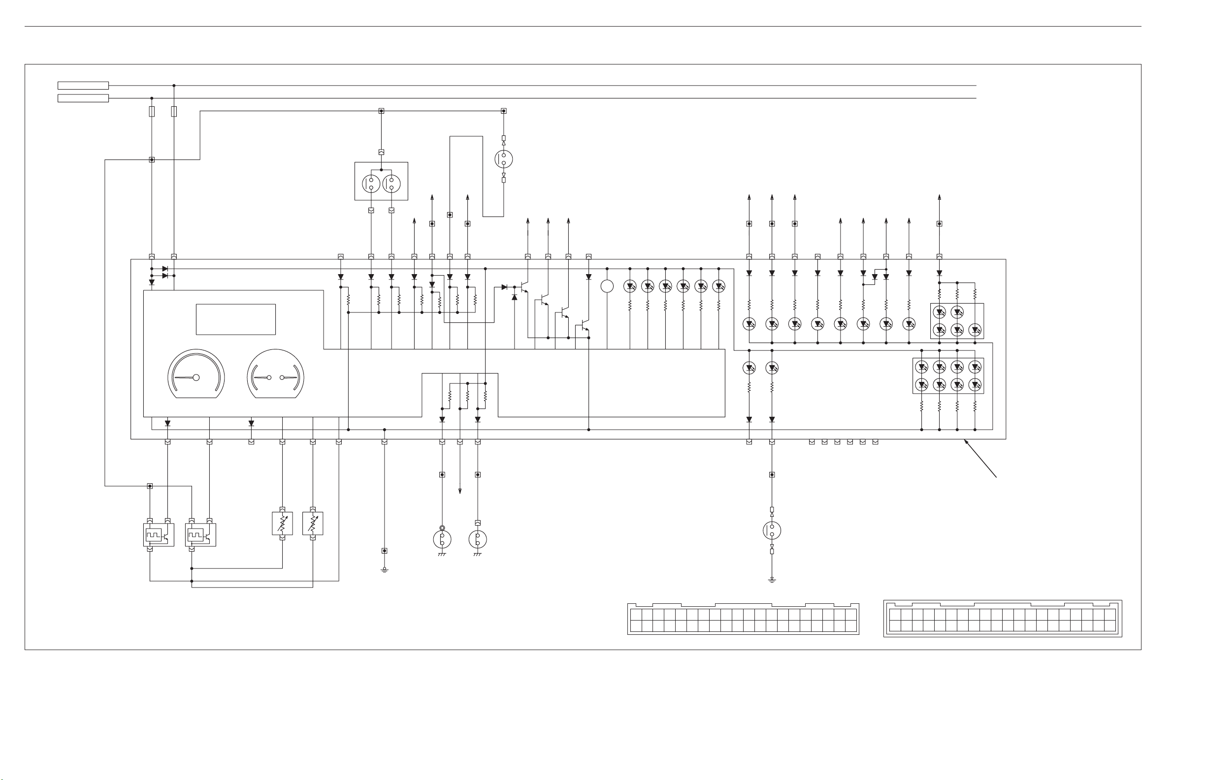
[3] INSTRUMENT PANEL BOARD (METER PANEL)
(A)
(B)
5A 5A
ELECTRICAL SYSTEM
0.5R/G
0.5R/G
0.5R/B
(1)
0.5R/G
3
0.85R/G
(4)
(2) (3)
(c)(b)
21
0.5R/B
0.5R/G
37 38 26 24 19 13 1 3 4 16 12 23 29 21
0.5L
0.5LG/B
10 1125
0.5G/W
0.5B/Y
0.5B/Y
0.5P/W
0.5V/W
0.5P/W
0.85V/W
0.5SB
0.5BR/R
(f)(e)(d)(a)
0.5G/OR
(8)
(9) (10) (11) (12) (13)
BZ
(g) (h) (i) (j) (k) (l) (m) (n)
0.5G/B 0.5G/B
0.5R/B
0.5R/B
0.5L/G
0.5W/R
0.5R
0.5GY/B
0.5BR
0.5B/R
15 14 31302
(21)
(5)
(14) (15) (16) (17) (18) (19) (20)
(30)
(22)
(6) (7)
0.5G/W
0.5G/W
(24) (25)
3TMACBG9P008A
(1) Display Mode Select Switch
(2) PTO/Hour
(3) Speed Unit
(4) PTO Change Switch
(5) LCD Display
(6) Tacho Meter
(7) Fuel/Temperature Meter
34 36 35 18 17 20 40 32 33 27 22 5678939
0.5R/G
32
1
0.5P/W
0.5B/W
0.5R/G
32
1
0.5Y/L
(26)
a
b
0.5Y
0.5B/W
0.5W/R
1
2
0.5B/W
(27)
0.5B/W
0.5B/W
0.5B
0.5W0.5W
M4
(28) (29)
(o)
0.5P
0.5W/G
0.5P
28
0.85BR/Y 0.5BR/Y0.85B
(31)
(32) (33)
20191817161513121110/31
4038373634333229/2421
(8) Engine Oil Pressure Indicator
(9) Charge Indicator
(10) PTO Indicator
(11) Heater Indicator
(12) Fuel Level Indicator
(13) Parking Indicator
(14) High Beam Indicator
(15) Turn Signal (L.H.) Indicator
(16) Turn Signal (R.H.) Indicator
(17) Trailer Indicator
(18) 4WD Indicator
(19) Bi-speed Turn Indicator
(20) Rear Differential Lock Indicator
(21) Back Light
(22) LCD Back Light
(23) Meter Panel
(24) Traveling Speed Sensor
(25) Engine Rotation Sensor
(26) Fuel Sensor
(27) Engine Coolant Temperature
Sensor
23/282726 30 31 / /
(28) Engine Oil Pressure Switch
(29) Parking Switch
(30) Air Cleaner Indicator
(31) Air Cleaner Switch
(32) Meter Panel (Wire Harness Side)
(33) Meter Panel Side
14/////2
(A) Light / Defogger
(B) ACC
(a) To Front Steer Turning Angle
(b) To Main Key (Start)
(c) To PTO Switch
(23)
2019181716151413121110987654321
40 39 38 37 36 35 34 33 32 31 30 29 28 27 26 25 24 23 22 21
(d) To Heater Relay
(e) To Engine Stop Relay
(f) To DT/Bi-speed Turn Relay
(g) To Light Switch (High Beam)
(h) To Flasher Unit (Output L)
(i) To Flasher Unit (Output R)
(j) To Flasher Unit (Trailer)
(k) DT/Bi-speed Switch
(l) DT/Bi-speed Switch
(m) Rear Differential Lock Switch
(n) To Light Switch
(o) To Alternator
L9-M4
Page 59

M9540Low Profile, WSM
KiSC issued 09, 2008 A
[4] WIRING COLOR
B ........... Black Br/B ........ Brown / Black Lg/Y ......... Light Green / Yellow
G .......... Green Br/Y ........ Brown / Yellow Or/W ......... Orange / White
L ........... Blue Br/R ........ Brown / Red P/W ............ Pink / White
P ........... Pink Br/W ........ Brown / White P/L .............. Pink / Blue
R ........... Red G/B ......... Green / Black R/B ............ Red / Black
V ........... Violet G/L ......... Green / Blue R/G ............ Red / Green
W .......... White G/Or ......... Green / Orange R/L ............. Red / Blue
Y .......... Yellow G/R ......... Green / Red R/W ............ Red / White
Br .......... Brown G/W ........ Green / White R/Y ............. Red / Yellow
GY .......... Gray G/Y ......... Green / Yellow V/W ............ Violet / White
Lg .......... Light Green L/B .......... Blue / Black W/B ............ White / Black
Or .......... Orange L/G .......... Blue / Green W/G ........... White / Green
Sb ......... Sky Blue L/Or ......... Blue / Orange W/L ............ White / Blue
B/G ......... Black / Green L/R .......... Blue / Red W/R ........... White / Red
B/L .......... Black / Blue L/W ......... Blue / White W/Y ........... White / Yellow
B/P .......... Black / Pink L/Y .......... Blue / Yellow Y/B ............ Yellow / Black
B/Pu ........ Black / Violet Lg/B ........ Light Green / Blue Y/G ............ Yellow / Green
B/R .......... Black / Red Lg/R ....... Light Green / Red Y/L ............. Yellow / Blue
B/W ......... Black / White Lg/W ....... Light Green / White Y/R ............. Yellow / Red
B/Y ......... Black / Yellow
ELECTRICAL SYSTEM
W1019456
L9-M5
Page 60
M9540Low Profile, WSM
KiSC issued 09, 2008 A
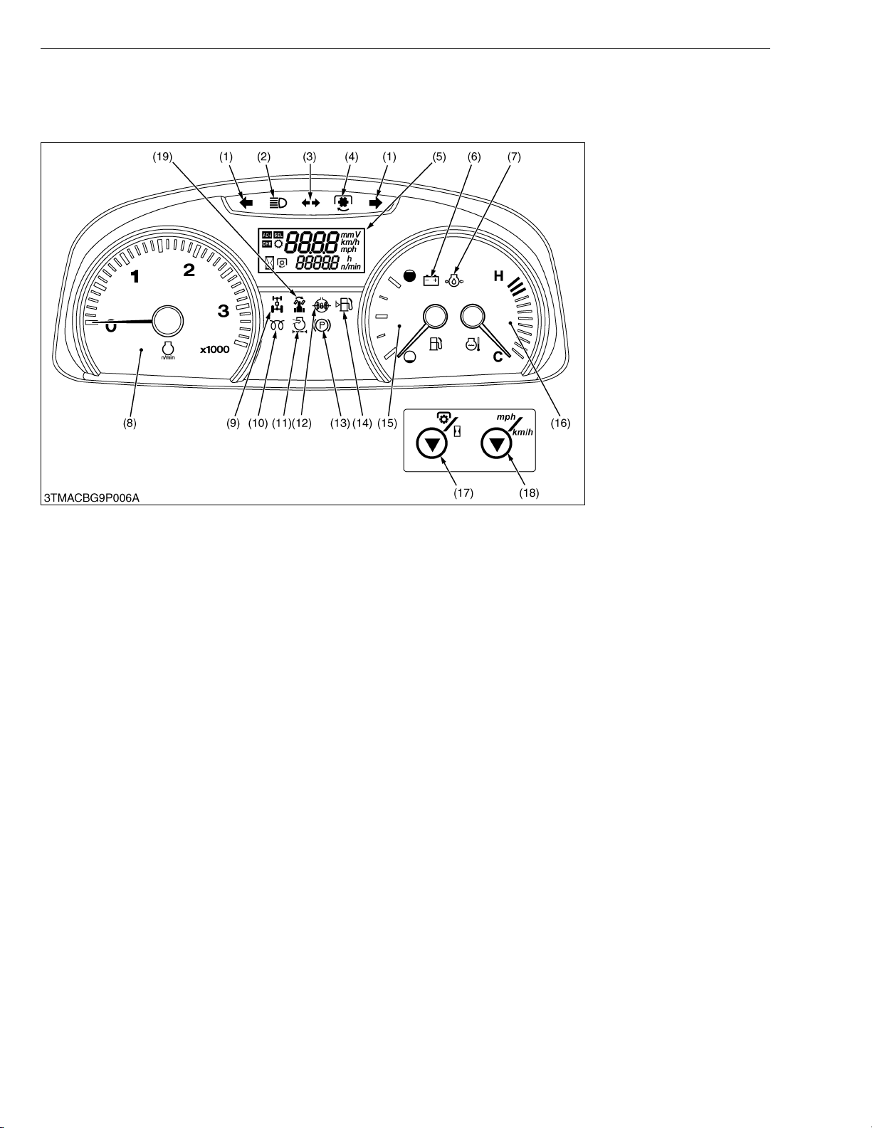
3. INSTRUMENT PANEL
[1] INDICATION ITEMS OF METER PANEL
ELECTRICAL SYSTEM
(1) Hazard / Turn Signal
Indicator
(2) High Beam Indicator
(3) Trailer Indicator
(4) PTO Clutch Indicator
(5) Liquid Crystal Display
(6) Electrical Charge Indicator
(7) Engine Oil Pressure
Indicator
(8) Tachometer
(9) 4WD Indicator
(10) Heater Indicator
(11) Air Cleaner Indicator
(12) Rear Wheel Differential Lock
Indicator
(13) Parking Brake Indicator
(14) Fuel Level Indicator
(15) Fuel Gauge
(16) Coolant Temperature Gauge
(17) PTO / Hour Meter Select
Switch
(18) Travel Speed Select Switch
(19) Bi-speed Turn Indicator
W1013347
L9-M6
Page 61

SERVICING
KiSC issued 09, 2008 A
CONTENTS
1. TROUBLESHOOTING ..................................................................................L9-S1
2. SERVICING SPECIFICATIONS ..................................................................L9-S2
3. CHECKING AND ADJUSTING ...................................................................L9-S3
[1] METER PANEL......................................................................................L9-S3
(1) Setting Mode (Entering Travel Speed Coefficient)............................L9-S3
(2) Checking Meter Panel, PTO/Hour Meter Select Switch and
Traveling Speed Select Switch .........................................................L9-S6
[2] 4WD / BI-SPEED TURN SYSTEM........................................................L9-S8
(1) Switch ...............................................................................................L9-S8
(2) Relays (PTO Safety, Key Stop, Work Light, Auxiliary Power and
4WD / Bi-speed Turn) .....................................................................L9-S10
(3) Solenoid Valve ................................................................................L9-S11
Page 62
M9540Low Profile, WSM
KiSC issued 09, 2008 A
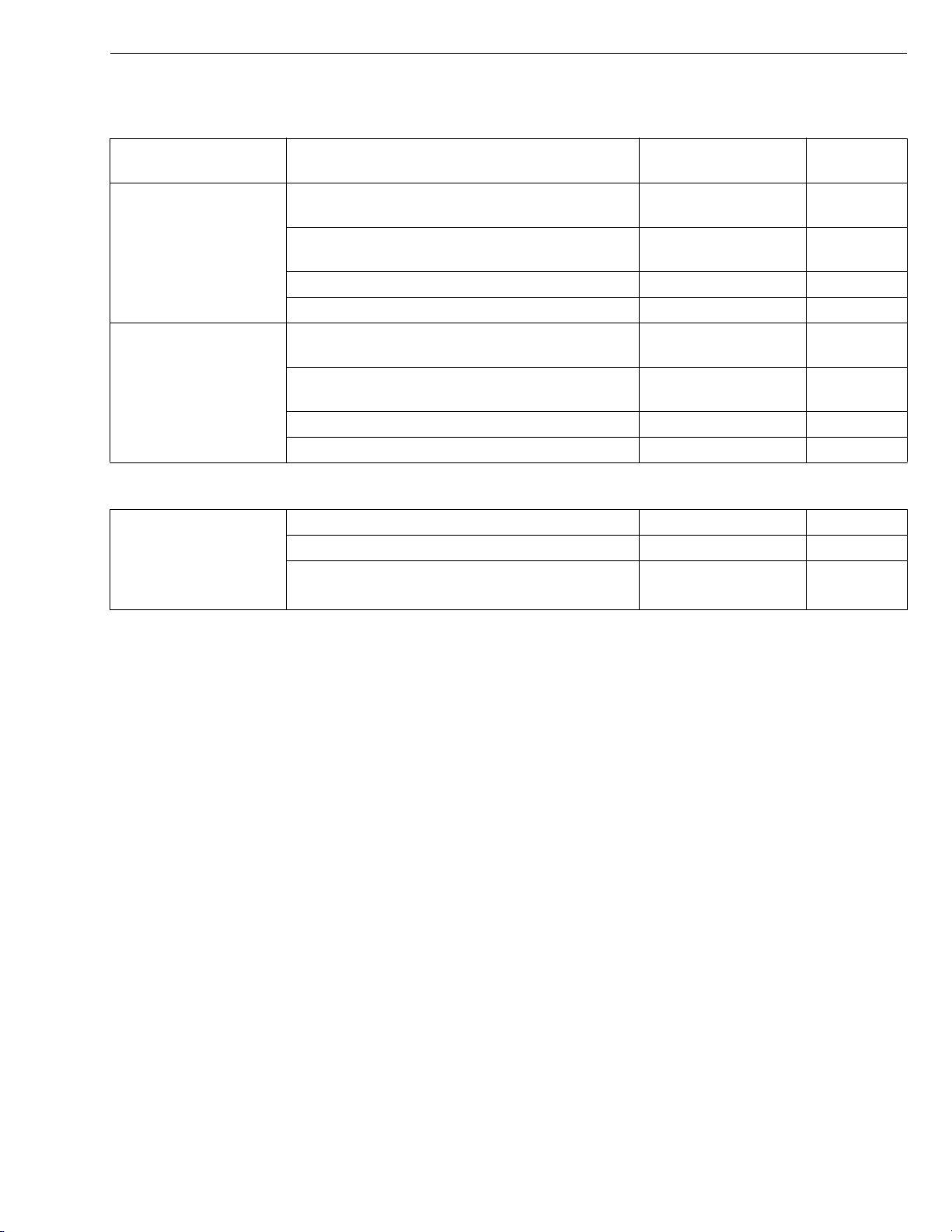
1. TROUBLESHOOTING
4WD / BI-SPEED TURN
Symptom Probable Cause Solution
Front Wheel Can Not
Drive Bi-speed Turn
Front Wheel Drive
Can Not Be
Cancelled Bi-speed
Turn
4WD / Bi-speed turn switch or wiring harness is
defective
Turning angle inspection switch or wiring
harness is defective
4WD / Bi-speed turn relay defective Replace L9-S10
Bi-speed turn solenoid valve defective Replace L9-S11
4WD / Bi-speed turn switch or wiring harness is
defective
Turning angle inspection switch or wiring
harness is defective
4WD / Bi-speed turn relay defective Replace L9-S10
Bi-speed turn solenoid valve defective Replace L9-S11
ELECTRICAL SYSTEM
Reference
Page
Replace L9-S8
Repair or Replace L9-S8
Repair or Replace L9-S8
Repair or Replace L9-S8
W1013580
EASY CHECKER
Bi-speed Turn
Indicator Lamp Does
Not Lights Up When
Under the Bi-speed
Condition
4WD / Bi-speed turn switch defective Replace L9-S8
Turning angle inspection switch defective Replace L9-S8
Bi-speed turn relay defective Replace L9-S10
W1013718
L9-S1
Page 63

M9540Low Profile, WSM
KiSC issued 09, 2008 A
ELECTRICAL SYSTEM
2. SERVICING SPECIFICATIONS
4WD / BI-SPEED TURN SOLENOID VALVE
Item Factory Specification Allowable Limit
4WD Solenoid Valve Resistance 10 to 12 Ω –
Bi-speed Turn Solenoid Valve Resistance 10 to 12 Ω –
W1013874
L9-S2
Page 64
M9540Low Profile, WSM
KiSC issued 09, 2008 A
ELECTRICAL SYSTEM
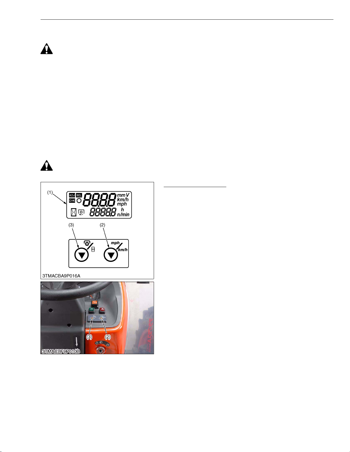
3. CHECKING AND ADJUSTING
CAUTION
• To avoid accidental short circuit, be sure to attach the positive cable to the positive terminal before the
negative cable is attached to the negative terminal.
• Never remove the battery cap while the engine is running.
• Keep electrolyte away from eyes, hands and clothes. If you are spattered with it, wash it away completely
with water immediately.
• Keep open sparks and flames away from the battery at all times. Hydrogen gas mixed with oxygen
becomes very explosive.
IMPORTANTQ
• If the machine is to be operated for a short time without battery (using a slave battery for starting), use
additional current (lights) while engine is running and insulate terminal of battery. If this advice is
disregarded, damage to alternator and regulator may result.
[1] METER PANEL
(1) Setting Mode (Entering Travel Speed Coefficient)
CAUTION
• To perform the meter panel, the operator must be seated on the tractor.
LCD Monitor Indication
The following settings and checking can be done by using the
LCD monitor (1), PTO/Hour meter select switch (3) and traveling
speed select switch (2).
1. Setting Mode :
Input the various dates (PTO speed display mode switching,
entering the traveling speed coefficient and model select) to the
meter panel.
2. Checking Mode :
Check a voltage of various sensor (fuel unit sensor, coolant
temperature sensor and monitor voltage (battery voltage)) or
rotation of engine.
(1) LCD Monitor
(2) Traveling Speed Select Switch
(3) PTO/Hour Meter Select Switch
W1011998
L9-S3
Page 65
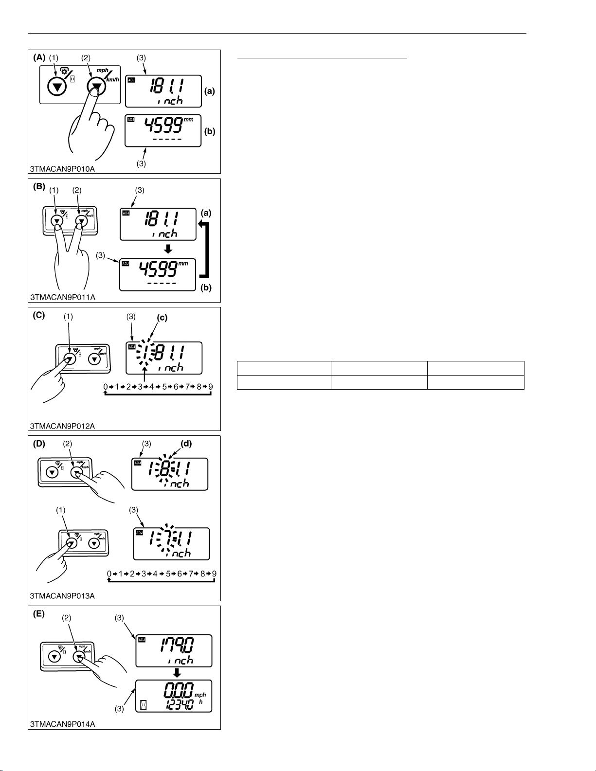
M9540Low Profile, WSM
KiSC issued 09, 2008 A
ELECTRICAL SYSTEM
Entering Traveling Speed Coefficient
[Example : Entering 179.0 inch]
1. While pressing the traveling speed select switch (2), turn the key
switch to “ON” position. The setting of the current tire’s
circumference is displayed in inches (a) or millimeters (b). The
highest-digit numeral starts flashing.
2. Each time both the PTO/Hour meter select switch (a) and
traveling speed select switch (2) are pressed at the same time,
the unit changes for inches (a) or millimeters (b). Select the inch
display mode.
3. Note that the highest-digit numeral (c) is flashing. Press the
PTO/Hour meter select switch (1) to select “1”. (The numeral
changes from 0 to 9 at each push of the switch.)
4. Press the traveling speed select switch (2), and the next highest
digit (d) starts flashing. Now press the PTO/Hour meter select
switch (1) to select “7”.
5. Enter “9” and “0” for the remaining digits in the same procedure.
6. Make sure the entry is “179.0”. Press and hold the traveling
speed select switch (2) longer than 2 seconds. The setting is put
in memory, and the LCD monitor (3) goes back to the hour meter
mode.
7. Turn the key switch to “OFF” position to exit.
NOTEQ
• The setting will be cancelled if the key switch is turned OFF
halfway in the procedure.
Tire circumference chart (reference)
Rear tire size Entry (in.) Entry (mm)
480/70R28 165.0 4190
(1) PTO/Hour Meter Select Switch
(2) Traveling Speed Select Switch
(3) LCD Monitor
(A) Procedure to enter the traveling
speed coefficient mode
(B) Procedure to select display for
inches or millimeters
(C) Procedure to select numerical at
highest digit
(D) Procedure to change next highest
digit and select numerical
(E) Procedure to put in memory
(a) Displayed in inches
(b) Displayed in millimeters
(c) Highest-digit numerical
(d) Next Highest-digit numerical
W1012141
L9-S4
Page 66
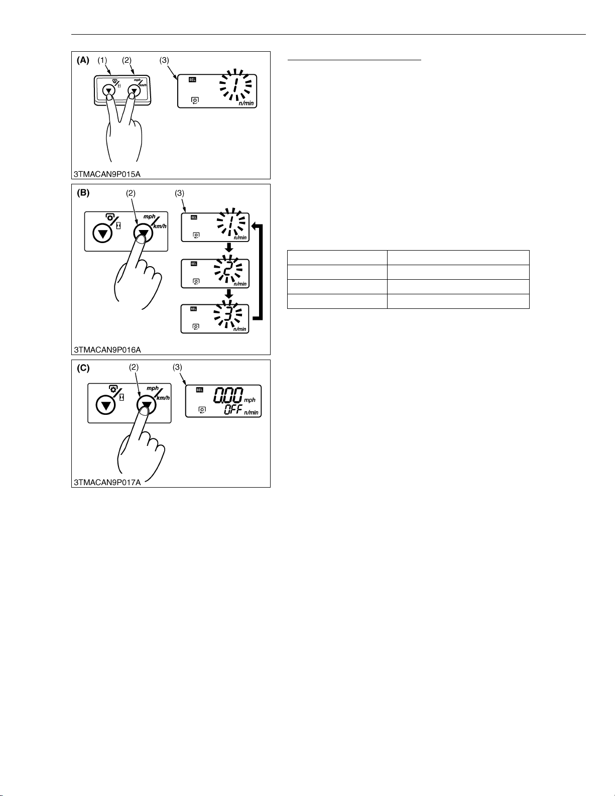
M9540Low Profile, WSM
KiSC issued 09, 2008 A
ELECTRICAL SYSTEM
Model Select (Setting Mode)
1. While pressing the PTO/Hour meter select switch (1) and
traveling speed select switch (2), turn the key switch to “ON”
position.
The current numerical code starts flashing.
2. Each time the traveling speed select switch (2) is pressed, the
code changes in order of [1] → [2] → [3] → [1]. Select the
appropriate code according to the table below.
3. Press and hold the traveling speed select switch (2) longer than
2 seconds. The setting is put in memory, and the LCD monitor
(3) goes back to the PTO speed display or hour meter display
mode.
4. Turn the key switch to “OFF” position to exit.
NOTEQ
• The setting will be cancelled if the key switch is turned OFF
halfway in the procedure.
Numerical code Tractor model
1 M8540, M9540 (LP)
2 M6040(N), M7040(N), M8540N
3Void
(1) PTO/Hour Meter Select Switch
(2) Traveling Speed Select Switch
(3) LCD Monitor
(A) Procedure to enter model select
mode
(B) Procedure to select numerical
code
(C) Procedure to put in memory
LP : Low Profile Model
N : Narrow Model
W1023923
L9-S5
Page 67
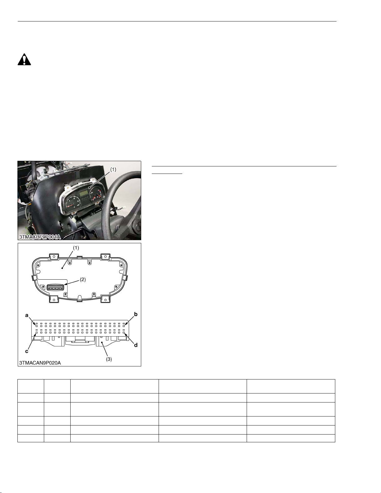
M9540Low Profile, WSM
KiSC issued 09, 2008 A
ELECTRICAL SYSTEM
(2) Checking Meter Panel, PTO/Hour Meter Select Switch and Traveling Speed Select
Switch
CAUTION
• For checking of electric circuit, use the circuit tester.
• As for the checking of sensors and switches, do the following order; check the battery, fuse and grounding
line first, check by the test function of meter panel next, and check the connectors of panel or related
electronic switch or sensor. If any defect is found there, check individual sensors or switches to see
whether the defect exists at the sensor and switch side or at the wire harness side.
• When any defect is not found for sensors, switches and harness, replace meter panel with new one.
IMPORTANTQ
• When connecting or disconnecting the connector for the purpose of checking, be sure to turn OFF the
main switch before hand. Moreover, pay attention not to allow the terminal to come in contact with other
terminal or chassis while checking.
• When applying the test pin of the tester to the connector terminals, use care not to damage to the
connector terminal.
Checking Connector Voltage, Sensor Resistance and Switch
Continuity
1. Remove the panel cover, refer to “[1] CLUTCH PEDAL” at “2.
CLUTCH” section (for ROPS model).
2. Remove the meter panel (1).
3. DIsconnect the 40P connector (2) from the meter panel.
4. Check the main voltage (battery voltage) first and check the
connector voltage, sensor resistance or switch continuity which
related for defective indication of meter panel as table below.
(When reassembling)
• Tighten the meter panel mounting screw evenly.
(1) Meter Panel
(2) 40P Connector Meter Panel Side
(3) 40P Connector Wire Harness Side
a : Terminal 1 (T1)
b : Terminal 20 (T20)
c : Terminal 21 (T21)
d : Terminal 40 (T40)
W1025566
Connector (40P) of Wire Harness Side
Terminal
No.
T1 SB Heater relay
T2 G/Or 4WD/Bi-speed relay
T3 Br/R Engine stop relay
T4
T5
Color of
wiring
Terminal Name Measuring across T40 (Ground) Condition
Battery voltage Main switch at ON
Battery voltage
Battery voltage Main switch at ON
Main switch at ON and 4WD switch
at 4WD position
L9-S6
Page 68

M9540Low Profile, WSM
KiSC issued 09, 2008 A
ELECTRICAL SYSTEM
Terminal
No.
T6
T7
T8
T9
T10 LG/B PTO/Hour meter select switch Battery voltage
T11 L Traveling speed select switch Battery voltage
T12 R/B Turn signal switch (R.H.) Battery voltage and 0 V (alternately)
T13 P/W PTO switch Battery voltage
T14 L/G Trailer indicator Battery voltage
T15 B/R High beam Battery voltage
T16 G/B Turn signal switch (L.H.) Battery voltage and 0 V (alternately)
T17 W/R Coolant temperature switch
T18 Y Fuel unit sensor Approx. 3.0 (F) to 112 Ω (E) Main switch at OFF
T19 V/W PTO change switch Battery voltage
T20 B/W GND (analogue)
T21 G/W Illumination light
T22
T23 B/Y Hazard Switch Battery voltage Hazard switch at ON
T24 B/W Main switch (start position)
T25
T26 G/W Turning angle inspection switch Battery voltage
T27 P Parking brake switch Battery voltage
T28 Br/Y Air cleaner switch Battery voltage
T29 W/G 4WD Switch Battery voltage
T30 R Bi-speed turn switch Battery voltage
T31 G/B Differential lock switch Battery voltage
T32 W Engine oil pressure switch
T33 W/G Alternator terminal L
T34 P/W Traveling speed sensor
T35
T36 Y/L Engine tachometer sensor Battery voltage Main switch at ON
T37 R/G Main switch (ON position) Battery voltage Main switch at ON
T38 R/B Main voltage (battery) Battery voltage
T39
T40 B GND
Color of
wiring
Terminal Name Measuring across T40 (Ground) Condition
Main switch at ON and PTO/Hour
meter select switch ON
Main switch at ON and traveling
speed select switch ON
Main switch at ON and turn signal
switch (R.H.) ON
Main switch at ON and PTO switch
OFF
Main switch at ON and turn the turn
signal switch under the trailer
coupler has connected
Main switch at ON and head light
switch at high beam position
Main switch at ON and turn signal
switch (L.H.) ON
Approx. 117 Ω at 120 °C (248 °F) to
5.88 kΩ at 0 °C (32 °F)
Battery voltage
Battery voltage Main switch at START
Main switch at ON and turning angle
Main switch at ON and parking brake
0 Ω At engine not run
Infinity At engine run
Approx. 10 V At engine run
Battery voltage Main switch at ON
Main switch at OFF
Main switch at ON and PTO speed
lever shifted at 540E position
Main switch at ON and head light
switch ON
inspection switch ON
switch at ON
Main switch at ON and air cleaner
switch at ON
Main switch at ON and 4WD switch
at ON
Main switch at ON and 4WD/Bi-
speed switch at Bi-speed turn
position
Main switch at ON and differential
lock switch ON
L9-S7
Page 69
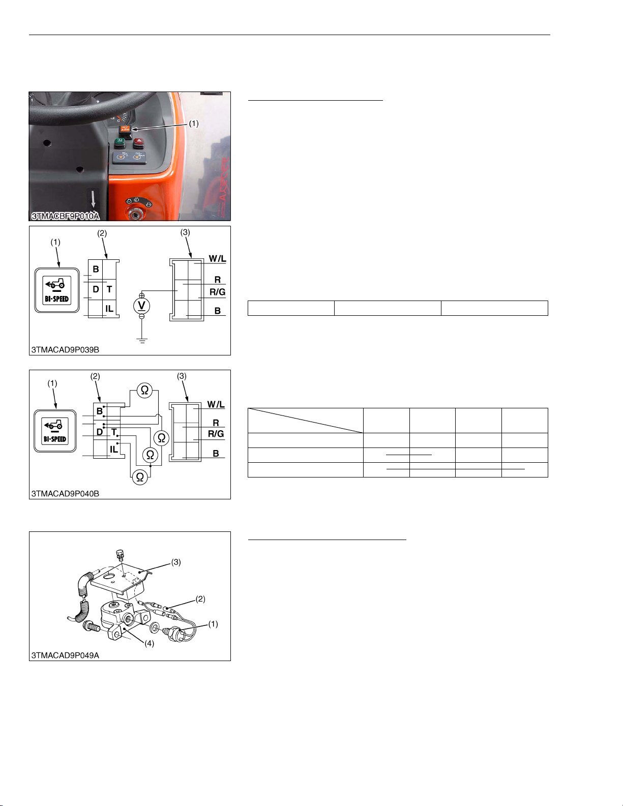
M9540Low Profile, WSM
KiSC issued 09, 2008 A
[2] 4WD / BI-SPEED TURN SYSTEM
(1) Switch
4WD / Bi-speed Turn Switch
1. Turn the main switch off.
2. Remove the 4WD / bi-speed turn switch (1).
(1) 4WD / Bi-speed Turn Switch
1) Connector Voltage
1. Turn the main switch to ON position.
2. Measure the voltage with a voltmeter across the connector R/G
terminal and chassis.
3. If the voltage differs from the battery voltage, the wiring harness
is faulty.
Vol ta ge R/G terminal – Chassis Battery voltage (11 to 14 V)
ELECTRICAL SYSTEM
W1013236
(1) 4WD / Bi-speed Turn Switch
(2) 4WD / Bi-speed Turn Switch
Connector (Switch Side)
(3) 4WD / Bi-speed Turn Switch
Connector (Wiring Harness Side)
W1013370
2) 4WD / Bi-speed Turn Switch
1. Check the continuity through switch with an ohmmeter.
2. If continuity specified below are not indicated, the switch is faulty.
Terminal
Position
OFF O
DT OO
Bi-speed OOOO
(1) 4WD / Bi-speed Turn Switch
(2) 4WD / Bi-speed Turn Switch
Connector (Switch Side)
DBTIL
(3) 4WD / Bi-speed Turn Switch
Connector (Wiring Harness Side)
W1013578
Turning Angle Inspection Switch
1. Remove the switch cover (3) from the left side front case support
(4).
2. Disconnect the turning angle inspection switch connector (2)
after turning the main switch off.
3. Perform the following checking 1) and 2).
(1) Turning Angle Inspection Switch
(2) Connector
(3) Switch Cover
(4) Front Case Support
W1013809
L9-S8
Page 70
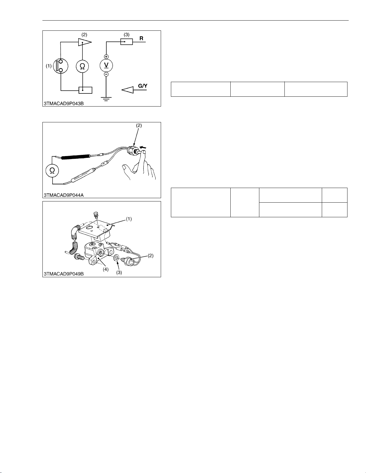
M9540Low Profile, WSM
KiSC issued 09, 2008 A
ELECTRICAL SYSTEM
1) Connector Voltage
1. Turn the main switch ON position.
2. Set the 4WD / Bi-speed turn switch to Bi-speed position.
3. Measure the voltage with a voltmeter across the wiring harness
connector B terminal and chassis.
4. If the voltage differs from the battery voltage (11 to 14 volts),
check the 4WD / Bi-speed turn switch or wiring harness.
Voltage
Connector B terminal
– Chassis
Battery voltage
(1) Turning Angle Inspection Switch
(2) 1P Connector (Switch Side)
(3) 1P Connector (Wiring Harness Side)
W1013974
2) Turning Angle Inspection Switch
1. Measure the resistance with an ohmmeter across the two 1P
connectors.
2. If infinity is not indicated, the turning angle inspection switch is
faulty.
3. Measure the resistance with an ohmmeter across the two 1P
connectors while pushing the push rod of switch.
4. If 0 ohm is not indicated, the turning angle inspection switch is
faulty.
Resistance across two
1P connectors
Factory
spec.
When the push rod is
normal position
When the push rod is
pushed
Infinity
0 ohm
IMPORTANTQ
• After reassembling the Bi-speed turn sensor, be sure to
check its operation.
1. When the front wheels are straight ahead, the resistance
value of the turn angle inspection switch is infinity.
2. When the turning angle exceeds approximately 0.57 rad
(32 °), the resistance value of the turning angle inspection
switch is 0 ohm.
If the resistance values specified above are not indicated,
adjust with the shim (3).
(Reference)
• Thickness of adjusting shim : 0.5 mm (0.020 in.)
1.0 mm (0.039 in.)
(1) Switch Cover
(2) Turning Angle Inspection Switch
(3) Shim
(4) Front Case Support
W1014436
L9-S9
Page 71
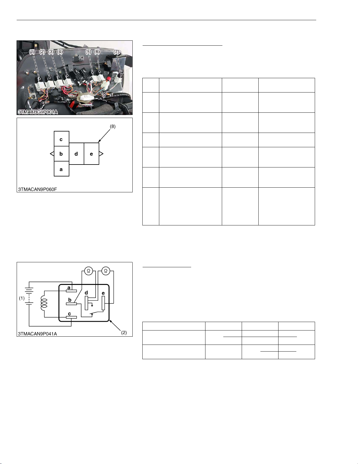
M9540Low Profile, WSM
KiSC issued 09, 2008 A
ELECTRICAL SYSTEM
(2) Relays (PTO Safety, Key Stop, Work Light, Auxiliary Power and 4WD / Bi-speed Turn)
Checking Connector Voltage
1. Measure the voltage with a voltmeter across the battery terminal
and chassis as table below.
2. If the voltage differs from the battery voltage, the wiring harness
or fuse is faulty.
Engine stop relay (main
(1)
switch at ON position)
PTO safety relay (main
(2)
switch at ON position and
PTO lever OFF position)
Work light relay (front)
(3)
(main switch at OFF
position)
Key stop relay (main
(4)
switch at OFF position)
Head light relay (low)
(5)
(main switch at OFF
position)
Head light relay (high)
(6)
(main switch at OFF
position)
4WD / Bi-speed turn relay
(main switch at ON, 4WD /
Bi-speed turn switch at bi-
(7)
speed position and turning
angle inspection switch at
ON)
Te rm i n al c –
Chassis
Te rm i n al c –
Chassis
Te rm i n al e –
Chassis
Te rm i n al e –
Chassis
Te rm i n al d –
Chassis
Te rm i n al d –
Chassis
Te rm i n al c –
Chassis
Approx. battery voltage
Approx. battery voltage
Approx. battery voltage
Approx. battery voltage
Approx. battery voltage
Approx. battery voltage
Approx. battery voltage
(1) Engine Stop Relay
(2) PTO Safety Relay
(3) Work Light Relay (Front)
(4) Key Stop Relay
(5) Head Light Relay (Low)
(6) Head Light Relay (High)
(7) 4WD / Bi-speed Turn Relay
(8) Connector (Wire Harness)
W1014836
Functional Check
NOTEQ
• The relays described here are used same ones so that these
are interchangeable.
1. Apply battery voltage across the terminals a and c, and check for
continuity across the terminals d and e.
2. If continuity is not established across terminals d and e, replace
it.
bde
At 0 voltage between
terminal a and c
At battery voltage between
terminal a and c
(1) Battery (2) Connector (Relay)
OO
OO
W1015402
L9-S10
Page 72
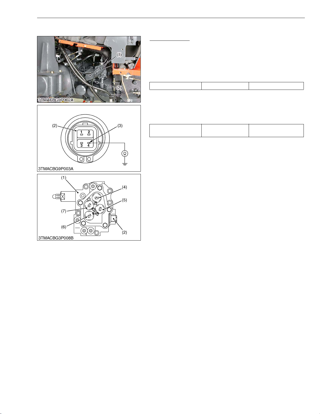
M9540Low Profile, WSM
KiSC issued 09, 2008 A
(3) Solenoid Valve
ELECTRICAL SYSTEM
Solenoid Valves
1) Connector Voltage
1. Remove the connector (2).
2. Set the 4WD/Bi-speed turn switch to bi-speed position.
3. Measure the voltage across the terminal 4 and chassis.
4. If the voltage differs from battery voltage, the wiring harness, fuse
or main switch is faulty.
Voltage Terminal 4 – Chassis Approx. battery voltage
2) Solenoid Valve
1. Disconnect the wire harness connector (2).
2. Measure the resistance with an ohmmeter across the each
terminal 4 on the connector (2) and chassis.
3. If infinity is indicated, the solenoid valve is faulty.
Resistance
Solenoid valve 4
terminal to chassis
10 to 12 Ω
(1) Solenoid Valve Assembly
(2) Connector
(3) Terminal 4 for Bi-speed Turn
Solenoid Valve
(4) PTO Solenoid Valve
(5) Bi-speed Turn Solenoid Valve
(6) 4WD Solenoid Valve
(7) Rear Differential Lock Solenoid
Val ve
W1016001
L9-S11
Page 73

EDITOR
KUBOTA FARM & INDUSTRIAL MACHINERY SERVICE, LTD.
64, ISHIZU-KITAMACHI, SAKAI-KU, SAKAI-CITY, OSAKA, 590-0823, JAPAN
PHONE : (81)72-241-1129
FAX : (81)72-245-2484
E-mail : [email protected]
KUBOTA Corporation
:
Printed in Japan 2008. 09, S, EI, EI, e Code No.9Y111-01660
2008. 08, S, EI, EI, e
 Loading...