

Page 1

701 RF Terminal Users Guide
Worth Data Inc.
11/05
Page 2
This equipment has been tested and found to comply with the limits for a Class A digital device, pursuant to
Part 15 of the FCC Rules. These limits are designed to provide reasonable protection against harmful
interference in a residential installation. This equipment generates, uses and can radiate radio frequency energy
and, if not installed and used in accordance with the instructions, may cause harmful interference to radio
communications. However, there is no guarantee that interference will not occur in a particular installation. If
this equipment does cause harmful interference to radio or television reception, which can be determined by
turning the equipment off and on, the user is encouraged to try to correct the interference by one or more of the
following measures:
• Reorient or relocate the receiving antenna.
• Increase the separation between the equipment and receiver.
that to which the receiver is connected.
Shielded cables and I/O cords must be used with this equipment to comply with the relevant FCC regulations.
Changes or modifications not expressly approved in writing by Worth Data may void the user's authority to
operate this equipment.
This device complies with Part 15 of the FCC Rules. Operation is subject to the following two conditions: (1)
this device may not cause harmful interference, and 2) this device must accept any interference received,
including interference that may cause undesired operation.
This device complies with RSS-210 of Industry Canada. Operation is subject to the following two conditions:
1) this device may not cause interference, and 2) this device must accept any interference, including
interference that may cause undesired operation of the device.
The 701 RF Terminal and B551 Base Station have been approved for use in the United States and Canada as a
low power frequency hopping spread-spectrum radio operating in the u nlicensed 902 MHz frequency range.
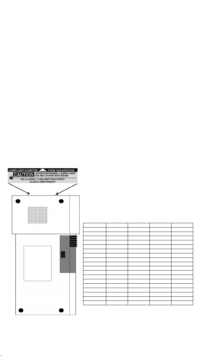
The LT701 model of this product has a laser scanner integrated with the Terminal as one unit. The laser used is a
There are no user adjustments or maintenance operations to be performed on the integrated laser scanner.
• Connect the equipment into an outlet on a circuit different from
• Consult the dealer or an experienced radio/TV technician for help.
Class II Laser Product and has a 1.2 Milliwatt Output. To operate
the laser scanner, aim the top of the case at a bar code, and press
the long green key on the keyboard of the R/F Terminal. The light
source will turn off, once a successful scan has occurred or 2.5
seconds has elapsed, whichever is first. Do not look directly into
the laser light source with the "Scan Key" depressed; avoid direct
eye contact with the laser light source.
The LTnn models of the RF Terminal as well as the LZ300 and
LZ400 Laser Scanners are covered by one or more of the
following U.S. Patents:
Patent # 4,360,798 4,369,361 4,387,297 4,460,120
4,496,831 4,593,186 4,603,262 4,607,156 4,652,750
4673,805 4,736,095 4,758,717 4,816,660 4,845,350
4,896,026 4,897,532 4,923,281 4,933,538 4,992,717
5,015,833 5,017,765 5,021,641 5,029,183 5,047,617
5,103,461 5,113,445 5,140,144 5,142,550 5,149,950
5,157,687 5,168,148 5,168,149 5,180,904 5,229,591
5,230,088 5,235,167 5,243,655 5,247,162 5,250,791
5,250,792 5,262,627 5,280,163 5,280,164 5,280,498
5,304,786 5,304,788 5,321,246 5,377,361 5,367,151
5,373,148 5,378,882 5,396,053 5,396,055 5,399,646
5,408,081 5,410,139 5,410,140 5,412,198 5,418,812
4,420,411 5,436,440 5,444,231 5,449,891 5,449,893
5,468,949 5,479,000 5,479,002 5,479,441 5,504,322
5,528,621 5,532,469 5,543,610 5,545,889 5,552,592
5,578,810 5,589,680 5,612,531
Page 3

Introduction
The 701 RF Terminal is a low cost, easy-to-use radio frequency interactive
terminal which communicates with PCs (or any computer) by serial port. This
new terminal offers unprecedented power and ease of use, while maintaining
compatibility with programs written for the older Worth Data Terminals. The
list of fantastic features include:
• Low Cost
• Up to 3000 feet range (10 x the competition)
• 64 Terminals per Base Station
• Spread Spectrum frequency hopping avoids interference
• No license required in USA and Canada
• Small size, (6.3" l, 3.3"w, 1.3"d) even with laser
• Certified to multiple 5 ft. drops to concrete
• Long Battery Life (24 hours of usage)
• Fast Recharging (2 hours) from External Power Supply
• No programming necessary on terminal
• Host communication thru Serial
• User Customizable Voice Prompting plus Display
• Backlit Display Standard
• Uses AA Alkaline or NiMH batteries
• Support for Receipt or Label Printer
• Support for an external serial keyboard
The RF Terminal maintains software compatibility* with applications written
for the older generation T71/LT71 RF Terminals.
*There is a difference in the number of characters that can be sent to the
Terminal. The new 700 RF Terminals have statement length limitation of 231
characters. See the Programming section for details.
11/05
Page 4

Table of Contents
Chapter 1 Installation ............................................................1-1
Components ............................................................. 1-1
Installation Sequence............................................... 1-1
Connecting the Base Station to a serial port............ 1-2
R/F Terminal Operation........................................... 1-4
Installing the R/F Terminal Utilities Software ........ 1-8
Chapter 2 RF System Setup..................................................2-1
RF Terminal Setup................................................... 2-1
RF Terminal Setup Parameters................................ 2-5
Base and Relay Setup ............................................ 2-23
Testing the RF link between base station and host ... 2-24
Chapter 3 Operational Theory...............................................3-1
How the Two-Way RF System works..................... 3-1
How the One-Way RF System works ..................... 3-3
How Site Testing works .......................................... 3-5
Chapter 4 Performance Issues .............................................4-1
Evaluating your area of planned operation.............. 4-1
Is radio traffic contention likely? ............................ 4-6
Chapter 5 Before you begin programming… ......................5-1
Failure Planning....................................................... 5-2
Chapter 6 Programming for the RF Terminal ......................6-1
LOW Level ASCII sequences directly .................... 6-1
LOW Level ASCII Sequences using a DLL ......... 6-12
PromptCOM/ActiveX............................................ 6-12
PromptNET TCP/IP Active X Controls ................ 6-22
Portable Printers .................................................... 6-32
Chapter 7 Voice Message Operations..................................7-1
Why Use Voice Messages and Prompts? ................ 7-1
RF Terminal’s Voice Message Mapping................. 7-2
Programming Voice Messages ................................ 7-2
Chapter 8 Troubleshooting ...................................................8-1
Appendix A Channel and Jumper Changes........................... A-1
Appendix B Adding Relays...................................................... B-1
Appendix C R/F Serial Pin-outs............................................... C-1
Page 5

Appendix D Firmware Upgrades .............................................D-1
Appendix E Code 39 Specifications........................................E-1
Appendix F Code 93 Specifications........................................ F-1
Appendix G Codabar Specifications...................................... G-1
Appendix H Code 128 Specifications......................................H-1
Appendix I Interleaved 2 of 5 Code Specifications ............... I-1
Appendix J UPC / EAN Specifications ................................... J-1
Appendix K MSI/Plessey Specifications .................................K-1
Appendix L How to scan a bar code....................................... L-1
Appendix M Using the Scan Stand......................................... M-1
Appendix N Optional Features ................................................N-1
Appendix O ASCII Code Equivalent Table............................. O-1
Index ........................................................................ 1
Page 6

Chapter 1
Installation
Components
The components in your R/F Terminal system will vary according to the
configuration of your system. Your R/F Terminal shipment should contain at least:
• An R/F Terminal T701 or LT701 (unit includes keypad and display).
If the R/F Terminal is an LT701 model, it will have an integrated laser
scanner built-in to the body of the terminal. Each terminal is shipped
with a shoulder strap, boot, and Setup Menu.
• An optional Scanner – if you ordered the T701 models instead of the
LT701 models with the built-in laser scanner.
• Optional rechargeable batteries and a 9v power supply.
• Utilities CD ROM – demo programs, DLL, and firmware loader program
If Base Stations were ordered with your system, you should receive at least:
• A Base Station (B551) including a 5v power adapter for each.
• A Serial Cable (F34 or F36) if a Base Station.
• A Relay Test Cable and junction connector block if ordering bases
as Relay Stations.
Keep the shipping box for the R/F Terminal in the event it is necessary to
return equipment for repair later.
Installation Sequence
1. Start with one Terminal and Base Station. Get everything working
with the single terminal and base and then add other terminals, being
certain that all terminals have unique Terminal IDs. After all terminals
are working, add the first relay. Then add remaining relays,
remembering to: 1) assign Relay IDs, and 2) set the jumpers of each
relay to terminated or not terminated properly.
2. All equipment is shipped with the default setting of Channel 0, Terminal
ID 0, and Relay ID 0. Unless you have other Terminal/Base
configurations already operating on that channel, you probably don’t
need to change the channel.
3. A Base and a Relay are the same product. A jumper change is all that is
required to use a Base station as a Relay. See Appendix A for details.
4. Without attaching the Base Station to the computer, and with only the
1-1
Page 7

power supply plugged in the base, you can perform a site test to be sure
you have adequate coverage and the radios are working perfectly. (See
Chapter 4).
5. Now connect the Base Station to the computer’s serial port. Be sure to turn
OFF all handshaking on the COM port used; in Windows, go to Start
Menu, Settings, System, Device Manager, Ports (COM and LPT). Now run
one of the RF Terminal demo programs found on the Utilities CD-ROM
6. Now run one of the demo programs to validate that everything is
working. If you have problems, refer to the Trouble Shooting Section.
Connecting the Base Station to a serial port
How it works…
The R/F Terminal transmits data to the Base station, which in turn transmits
the data to the host serial port. The computer software reads the data
coming through the serial port and processes the information accordingly.
When the computer software running on the host has a task for the terminal,
it transmits data out to the serial port, which then passes this data on to the
Base station. The Base station then broadcasts the message to the terminal,
causing the terminal to display the message to the user.
The Base station is not machine-sensitive (it needs a standard RS-232 serial
port) nor is it operating system dependent (you just need to be able to read
and write to the serial port as a separate device).
Connecting the Base station…
If you specified a 25 pin cable (part #F34) or a 9 pin cable (part #F36) when
you ordered your Base station, simply plug the RJ45 end of that cable into
the COMPUTER port on the Base station, and the 25 or 9 pin end into
your computer’s serial port. If you are not connecting to a PC, see
Appendix C for cable and serial pin-outs.
.
If your extension cable is over 80 feet long and you are running Windows,
open up the DB9 or DB25 connector on the base station side and cut the
unused pins (see Appendix C.).
For an extension cable, you can use existing network cabling already in
existence, but you must be certain that the Transmit and Receive data lines
are not in the same twisted pair.
If you are using an extension cable and are having problems, test the cable by:
1. Connecting the Base station without using the extension cable.
Simply plug in the F34 or F36 cable that came with the Base.
2. If the Base works with only the F34 or F36 cable in place, add in
the extension cable without changing the physical location of the
Base station. If the extension cable appears to be the culprit, check
to be sure that Transmit lines are connected to Receive lines.
1-2
Page 8

Configuring the Base station…
After connecting the Base station to your serial port, you need to configure
the serial settings on the Base station to match those required by your
software. The default settings are:
• 9600 baud
• No parity
• 8 data bits
• 1 stop bit
• “None” protocol setting
You may want to increase the baud rate for performance. If you want to
change any or all of these settings, see Chapter 2 for details on configuring
the Base station using the 700 RF Base Station Serial Configuration
Utility.
Base station channel…
To determine what channel your Base station is set to, plug in the power
supply and watch the LED light on the front of the Base station. The LED
will blink “the channel + 3” times.
For example, the default channel is 0. On power up, the LED on a Base
station set to channel 0 would blink 3 times. A Base station set to channel 5
would blink 8 times.
If this is the only Base station operating, leave the channel at 0. If you have
other Base stations in the area and need to change the channel, see
Appendix A; Channel and Jumper Changes for details on how to open the
Base station and set the rotary switch inside to the desired channel.
1-3
Page 9

R/F Terminal Operation
Using the RF Terminal keypad…
The R/F Terminal is turned on by pressing the green
ON/OFF button located in the upper left-hand corner
of the R/F Terminal keypad.
The R/F Terminal has a Shut Down Time feature that allows you to
determine the length of time the R/F Terminal must be inactive before
automatically shutting down to conserve battery power. When the R/F
Terminal shuts down, simply press the ON/OFF button to resume operation.
The keypad is custom designed for the R/F Terminal operations. It has
numeric and control keys in the non-shifted state, and alpha characters in its
shifted state. You can readily determine if the SHIFT is on by the cursor on
the display. When SHIFT is on, the cursor is a large black rectangle. When
SHIFT is off, the cursor is a narrow underline character. For all prompts
which ask for a YES or NO response, the ENTER key, is the YES reply,
and the 0 (zero) key is the NO reply. As you key data, you will see each
character displayed on the screen. If you make a mistake, you can delete the
last character by pressing the DELETE key, or you can clear all characters
displayed on the screen by pressing the CLEAR key.
You can order NIMH batteries (L01) from Worth Data along with a 9v
recharging Power Supply that recharges the batteries completely within 2
hours. When recharging options are ordered with the Terminals, the
Terminal's Batteries Setup parameter is set for recharging "1" which allows
the batteries to be recharged under program control. Otherwise, the batteries
shipped are alkalines with no recharging options set in the Terminal.
However these are changeable by the customer. Using NIMH or alkaline
batteries, you should get 24 hours of operation (assuming 1 transaction
every 8 seconds).
If you did not order the rechargeable batteries and you change to
rechargeables, you must change the Terminal's Setup to Batteries 1 to allow
recharging. If you want to charge the batteries without having to remove
them from the Terminal, you must use the Worth Data 9v power supply.
You can safely use alkaline batteries in a terminal set for recharging,
providing you don’t plug a power supply into the terminal. Recharging
Alkaline batteries may cause the batteries to explode and leak battery acid
throughout the RF Terminal. Battery acid damage is not covered by the
Worth Data warranty because it not deemed to be “normal use”.
If you are using alkaline batteries (either regular or rechargeables) and
have selected the Rechargeables setting in the Battery setup parameter (See
Chapter 2; RF System Setup), the RF Terminal will generate the following
error message:
1-4
Page 10

Alkaline Batteries
Detected,
Rechargeables Are Specified
Do Not Recharge
Battery Life Indicator
The R/F Terminal detects low AA batteries and displays the following message:
LOW BATTERIES
Finish, Sign Off
Change Batteries
Hit Any Key_
At this point you have approximately 2 minutes of operational time to finish
your transaction (or note where you are leaving off if in the middle of a
transaction) and sign off. After 2 minutes, the R/F Terminal displays:
CHANGE BATTERIES
UNIT SHUT DOWN_
This message displays for 20 seconds before the R/F Terminal signs off from
the host (if signed on) and then shuts itself down. If you turn it back on
without changing batteries, you may experience constant beeping, intermittent
scanning, and very irritating symptoms that look like equipment failure.
Once you remove the batteries, you have 5 minutes to change them before
you lose the date and time in the Real-Time Clock.
The R/F Terminal also has a battery life indicator that can be accessed while
operating in ONE-WAY or TWO-WAY mode or while in the MENU. To
display the remaining battery life of the AA batteries (as well as the date
and time) press the STATUS key:
mm/dd/yy hh:mm
AAxBAT-zz%
x=a when Alkaline batteries are specified in Battery
x=n when NiMH or NiCad batteries specified in Battery
zz=percent in numbers i.e. 99, 10, 05
Press the STATUS key again to resume processing.
setup
setup
To change the AA batteries:
1. Turn OFF the R/F Terminal.
2. Remove the battery holder door on the back of the R/F Terminal by
pressing down on the grooved portion of the door and pushing outward.
3. Remove the old batteries and insert the new ones, making sure to
orient the batteries with the positive (+) end facing down toward
the bottom of the R/F Terminal.
1-5
Page 11

4. If using rechargeable batteries, make sure that rechargeables are
specified. See the previous page to quickly determine the setting
using the Status key.
5. Replace the battery door and turn the reader on using the ON/OFF
switch.
6. Sign ON and resume your application.
Recharging the batteries
1. Be sure you have specified rechargeable batteries in the RF
Terminal's Setup. If you ordered rechargeable batteries with a RF
Terminal, Worth Data makes the change before shipping. See
Battery in the RF Setup.
2. With the RF Terminal shut off, plug the 9V power adapter into the
RF Terminal, (the 5volt power supply used for the Base Station
and the older RF Terminals cannot be inserted).
3. The firmware in the terminal then checks the level of charge in the
batteries to see if they need charging, displaying the following message:
4. If the batteries are already charged, the message will disappear. If
the batteries need charging, the following message is displayed:
Checking Batteries
Please Wait………..
Charging Batteries
Please Wait………..
R/F Terminal Menu Functions
There are four modes of operation for the R/F Terminal:
SIGN ON Signs R/F Terminal on for two-way communication
with host.
SETUP MODE Accesses Setup parameters for Terminal and Base.
ONE-WAY Allows “dumb” data entry to computer. No
prompts from host computer
SITE TESTING Allows user to test range and evaluate site to
determine best position for Base. Also the acid test
for suspected radio failure.
Upon power-up, the R/F Terminal displays the following opening screen:
R/F TERMINAL 3C1nnnx
TERM ID: 0 R:nn
USA CHANNEL: 0 6/6
HIT ANY KEY
(The opening screen can be bypassed upon power up. See Chapter 2)
1-6
Page 12

• The first line on the screen, R/F TERMINAL 3C1nnnx, gives the
firmware revision number.
• TERM ID: 0 refers to the current Terminal ID. The default setting
is 0. Every Terminal must have a unique ID. R:nn refers to the
version of the radio processor firmware.
• Line 3 refers to the channel currently used by the R/F Terminal.
USA CHANNEL: 0 refers to a Terminal set to channel 0. The
second part of this line identifies the display lines. Possibilities are
6/4 (6 line terminal operating in 4 line mode and 6/6 (6 line
terminal operating in 6 line mode).
To move on to the first menu item, press any key on the R/F Terminal
keypad. The display now reads:
SIGN ON?
KEY [YES/NO]?_
• Press the YES key to SIGN ON to a two-way communication
host computer program through the Base station.
• Press NO to move on to the next menu item:
SETUP MODE
KEY [YES/NO]?_
• Pressing YES prompts for a password to enter the Setup Mode
for the R/F Terminal or Base station.
• Press NO to move on to:
ONE-WAY MODE
KEY [YES/NO]?_
• Press YES to enter ONE-WAY mode. ONE-WAY mode
allows the R/F Terminal to transmit data to the host computer
without prompting from the host computer program – we call
this “dumb” data entry. (If you want a Terminator Character
on the bar code, you will have to enter a Postamble using the
Setup Menu). ONE-WAY mode is also useful for demos, as it
does not require any interaction from the host computer.
• Press NO to go to:
SITE TESTING
KEY [YES/NO]?_
• Press YES to enter SITE TESTING. SITE TESTING is an
excellent way to assess your R/F communication in any area.
It can help you determine the best place to locate your Base
station for maximum R/F performance as well as troubleshoot
1-7
Page 13

problems that may relate to range or interference.
• Press NO to loop back to the SIGN ON? prompt.
You can back-out of any mode or prompt by pressing the F1 key. For
example, if you press YES at the SETUP MODE? prompt but really meant
to press NO, press the F1 key to take you back to the menu. The F1 key on
the R/F Terminal keypad works like the ESC key on the PC – it will usually
get you out and back to the previous step. You can use the F1 key to exit
and SIGN OUT when using a Two-Way communication program running
on the host computer.
The entire mode menu can be skipped (see Chapter 2; RF System Setup),
causing the R/F Terminal to automatically SIGN-ON or go to ONE-WAY
mode on power up.
Installing the R/F Terminal Utilities Software
The R/F Terminal system ships with a CD of programs for use with the R/F
Terminal and Base station. The CD contains programs for the TriCoder and
the RF Terminal. Click on the RF Terminal button.
Next you have the choice of installing the following:
Windows Demo Programs and RF DLL Programmers Library
• Demo Programs in VB, Access, and Delphi
• 16 bit and 32 bit DLLs
• VB DLL-based QL3 printer demo program
Windows 700 RF Base Serial Configuration Utility
ActiveX Tools
• Serial Interface (includes Excel and VB demos)
• TCP/IP (includes VB/Access and Delphi demos)
Windows 700 RF Terminal Firmware Loader Program
DOS/BASIC source demo programs
Click on the set of programs you wish to install.
To install any of the programs found on the Utilities CD, simply insert the CD
into your CDROM drive. The install program should start automatically. If it
does not, simply run the SETUP.EXE program found on the CD.
Running the demo programs…
The demo programs are all programs provided to help you test your R/F
Terminal with a two-way communication program.
Using the Windows 700 RF Terminal Loader Utility
The R/F Terminal Loader program is a Windows application that allows
1-8
(requires GWBasic or QBasic)
Page 14

you to download new R/F Terminal firmware from Worth Data into your
R/F Terminal, Base or Relay. New firmware can be obtained on CD ROM
directly from Worth Data or downloaded via the Web at:
http://www.barcodehq.com/download.html
Installing the Windows Terminal Loader Utility
This program is for Windows 98, NT, 2000, XP, and ME:
1. Insert the CD into your CDROM drive. The "Hardware Utilities
Installation" program should start automatically. If it does not,
double click on the SETUP.EXE program on the CD in Windows
Explorer.
2. Click on the RF Terminal button to select the type of hardware.
3. Click on the "Install RF Loader" button.
4. Follow the installation instructions on the screen.
Setup installs three programs and creates a program group for them:
R/F TERMINAL EPROM LOADER HELP
R/F TERMINAL EPROM LOADER
UNINSTALL
See Appendix D; Firmware Upgrades for details on how to use the
EPROM Loader programs (Windows).
1-9
Page 15

Page 16
Chapter 2
RF System Setup
RF Terminal Setup
The RF Terminal itself can be configured using the Terminal keypad or by using
the bar coded Setup Menu. Even if you configure the RF Terminal using the
keypad, you may need the bar coded Setup Menu to use as a reference. Most
users do not need to change anything in the setup. The most commonly changed
setup parameters are the Terminal ID (especially if you have more than 1
terminal) and the Channel (if you are adding an additional Base station). Some
parameters are available only by bar code menu and others only by keypad:
Bar Code Menu Only Keypad Only
Characters Security Code
Reset Relay Existence
Control Keys Only
Skip Opening Screens
Display of Year
Date and Time
Aiming Dot Duration
Automatic Check Back
Display Backlighting
If you are using the bar coded Setup Menu and are unfamiliar with scanning bar
codes, see Appendix M; How to scan a bar code to learn proper scanning
technique before you begin scanning the bar codes on the Setup Menu.
RF Terminal Default Settings
This is the default configuration of the RF Terminal as it is shipped from
the factory. If you ever need to return the RF Terminal to these default
settings, use the bar coded Setup Menu and scan the following bar codes in
this sequence:
• START SETUP
• RESET
• END SETUP
2-1
Page 17
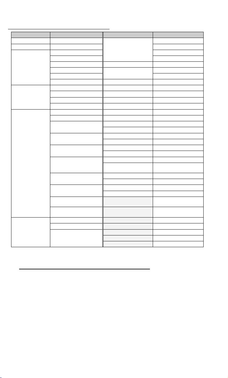
Default RF Terminal Configuration
Parameter Default Setting Parameter Default Setting
Radio Terminal ID
RF Channel
Code 39
2 of 5 Code
UPC/ EAN
Codabar
*All parameters are set back to their defaults when reset using the bar coded Setup Menu, even
parameters that are changed by keypad only. Shaded items are keypad access only.
0 Disabled
0 check digit not transmitted
Enabled Plessey Code disabled
Accumulate Mode ON
stop/start chs not xmit
check digit disabled EAN/UCC 128 disabled
Caps lock OFF
Disabled
I 2 of 5 Code disabled
6 digit code length
check digit disabled
Enabled
UPC supps disabled
UPC-A NSC & check digit
transmitted
transmitted
check digit transmitted
EAN-13 country code &
check digit transmitted
UPC-E 1st char & check
digit not transmitted
UPC-E 1st char & check
digit not transmitted
EAN-8 1st char & check
digit not transmitted
EAN-8 1st char & check
digit not transmitted
Disabled
Start/Stop not transmitted
CLSI format disabled
MSI Code
Code 128
Code 11
RSS-14
Code 93
Beep Tone
Preamble
Postamble
Date Format
Baud Rate
Parity
Data Bits
Stop Bits
Batteries
Speaker
Laser Options
Shut Down Time
Voice Messages
Characters
Security Code
Control Keys Only
Display of year
Skip opening screens
Aiming Dot
Automatic Check Back
Display Backlight Duration
Label Code5 disabled
Enabled
Disabled
Disabled
Disabled
Full ASCII disabled
medium
none
none
mm-dd-yy
9600 UPC-A NSC & check digit
none
8 EAN-13 country code &
1
Alkaline default
Speaker Volume 5
Headphone Volume 5
none
5 minutes
303015
none reassigned
none
no
2 digit
no
No
No
5 seconds
Using the bar code RF Terminal Setup Menu
To use the bar coded RF Terminal Setup Menu, scan these bar codes in this
order:
• Start Setup - you should hear 2 beeps
• Setup Parameter bar code (i.e. “Beep Tone”)-you should hear 2
beeps for each scan
• Number bar code that corresponds to the appropriate setting
(i.e. “3” to change the Beep Tone to “high”) - you should hear 2
beeps for each scan
• End Setup-you should hear 3 beeps after END SETUP.
2-2
Page 18

More than one Setup Parameter can be changed before you scan END
SETUP. For example, if you scanned START SETUP, then “Beep Tone”,
then 3, then “Speaker Operation”, then 1, then END SETUP, this would
change the beep tone to “high”, and turn the speaker "off".
If you are using a Laser Scanner to setup the RF Terminal, the beam will
often cover more than one bar code. Cover any adjacent bar codes before
scanning, and then check the RF Terminal display to make sure the correct
setting was entered.
Using the keypad to setup the RF Terminal
The RF Terminal can be setup via the Terminals' keypad by entering Setup
Mode from the menu. Turn on the Terminal and press any key. You should
see the SIGN ON? message:
SIGN ON?
KEY [YES/NO]?_
Press the NO key. The next prompt is the SETUP MODE? prompt:
SETUP MODE?
KEY [YES/NO]?_
Press the YES key. At this point, the terminal will ask for a password:
SETUP MODE
PASSWORD?_
Enter WDTRI on the keypad. The next item allows you to choose which
item to configure:
R/F Terminal------->1
R/F Base Setup--->2
Voice Operations->3
Press 1 to enter the RF Terminal Setup. Now you are in the RF Terminal
Setup Menu and can choose from the following options:
RF Setup---0 Batteries--4
BarCodes--1 Speaker---5
RS232-------2 Other------6
Date/Time--3 Exit-------F1
At this point, choose which group you want to configure. Most of the RF
Terminal setup parameters are accessible from the either the keypad Setup
Menu or the bar code Setup Menu. There are only 2 that are available only
from the bar code Setup Menu while there are quite a few options that are
available only from the keypad Setup. See the beginning of this chapter for
a comparison of the two Setup Menus.
2-3
Page 19
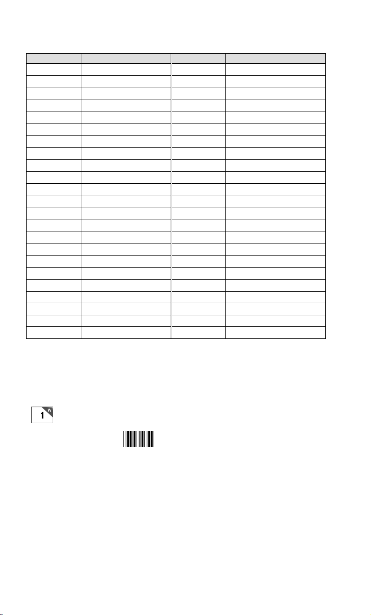
The groups in the keypad Setup Menu contain the following setup parameters:
R
Setup Group Parameter Setup Group Parameter
RF Setup
0 RF Channel 3 Set Date
Security Code
Skip opening screens
Bar Codes
1 UPC/EAN
Code 2 of 5/I 2 of 5
2 of 5 Length 5 Headphone Volume
Code 128 Beep Tone
Codabar
MSI/ Plessey
RS232
2 Protocol Automatic Check Back
Parity Control Keys Only
Data Bits LCD Display Mode
Stop Bits LCD Backlight
LCD Backlight Duration
RF Terminal ID
Code 3 of 9 4
Code 11 6 Preamble
Code 93 Postamble
RSS-14 Voice Messages
Laser Options
Baud Rate Aiming Dot Duration
Date/Time
Battery
Speaker
Other
Set Time
Date Format
Display of Year
Recharging or Not
Speaker Volume
Shut Down Time
Once you have selected a group to edit, you will see each parameter
displayed in the order listed above. Use the next section of this chapter as a
reference for all RF Terminal Setup Parameters, whether they are
configured using the keypad or the bar coded Setup Menu. Each parameter
is followed by either a key symbol:
and the group you will find the parameter in,
or a bar code symbol:
F
Setup
or both, depending on how the parameter can be configured.
2-4
Page 20

RF Terminal Setup Parameters
R
Default settings are shown in bold type in this manual and are marked by a * on
the bar code Setup Menu.
The RF Terminal will typically require no setup changes except, Terminal ID (if more
than one terminal) and enabling bar codes to be read other than UPC or Code 39.
RF Terminal ID
Default ID 0
Available ID's 0-9, A-Z,
a-z, - =
• Every terminal needs a unique Terminal ID. The default Terminal ID
is always shipped as 0. If you have more than one RF Terminal
assigned to a Base Station, you must be sure that each RF Terminal has
a unique Terminal ID, (otherwise you will have big troubles including
false error messages). The Terminal ID is always displayed on the
Start Up screen when you power up the terminal. There are 64
Terminal ID's available - 0-9, A-Z, a-z, and the special characters "-"
and "=". To change the Terminal ID, enter one character either by
scanning from the bar code Setup Menu or by pressing a key on the RF
Terminal keypad. The channel setting is displayed on the RF
Terminal’s opening screen.
RF Terminal Channel
Default Channel 0
• The terminal's radio operates by "frequency hopping" spread spectrum.
The radios hop from one frequency to another very 400ms. The radio
goes through 25 different frequencies and then repeats the sequence –
all in the 902 MHz band at 150 milliwatts of power. Different
sequences define the channels. It is possible to have more than one RF
Network in the same area, providing each RF Network is on separate
channels to avoid interference and general confusion.
F
Setup
• The default Channel is always shipped as 0. There are 10 channels in
the USA. The Channel can be set by entering the corresponding
characters (0-9) either by scanning the bar coded Setup Menu or by
entering the character from the RF Terminal keypad.
• All Terminals, Base Stations and Relays in the RF Network must be set
to the same channel. The channel is always displayed on the Start Up
screen when you power up the Terminal. It is possible to have more
than one RF Network in the same area, providing each RF Network is
on separate channels to avoid interference and general confusion.
2-5
Page 21
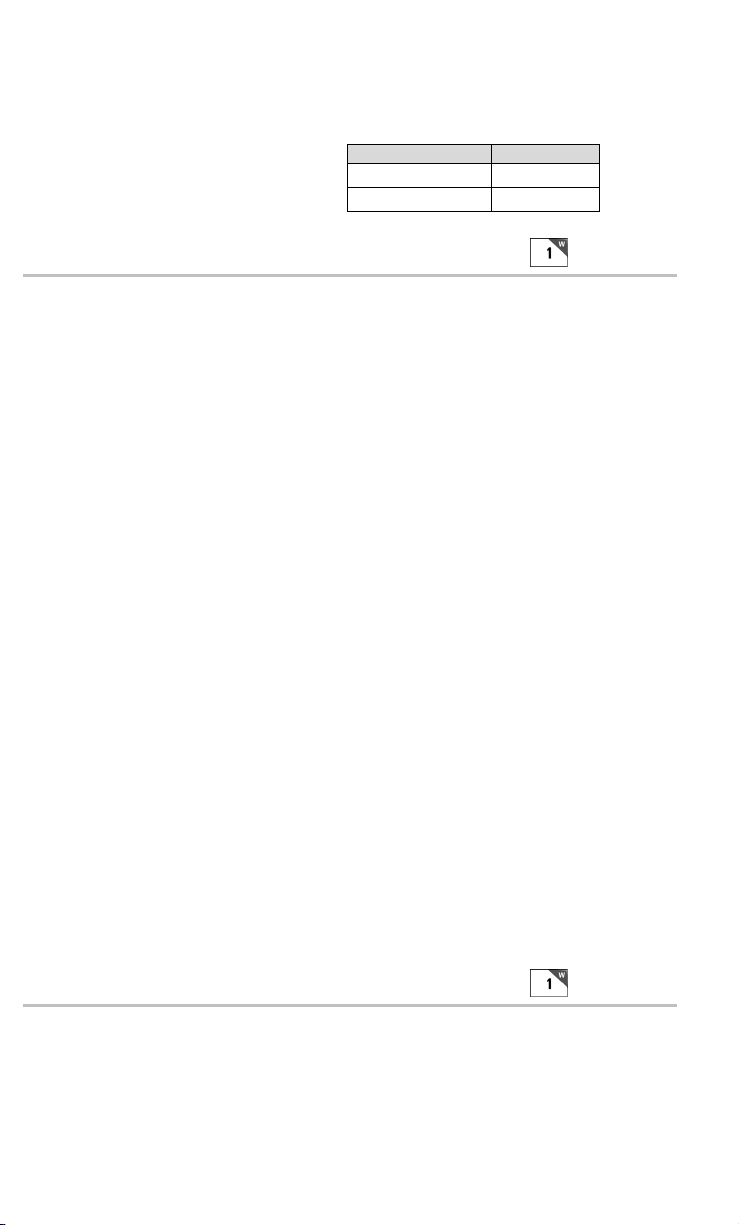
There are 10 channels of frequency hopping available for the US, Canada
R
and Mexico operating in the 902 MHz band. These channels display as
"USA Channel" on the screen upon power-up of the Terminal. The channels
in MHz are:
USA Versions
RF Terminal RFU1nnnx
Base Station BSU1nnnx
Security Code
Disabled 0
Enabled 1
F
Setup
• A Security Code can be utilized to minimize the possibility of a Base
Station listening to data from a Terminal that is talking to a different Base
Station. A Security Code can also prevent interference from having many
Base Station/RF Terminal configurations in one area; i.e. a merchandise
mart with multiple vendors all running RF Terminal networks.
• A Security Code consists of 3 characters - any combination of ASCII
33 - ASCII 126. This allows for the possibility of more than 830,000
different character combinations. The characters are entered using the
bar coded FULL ASCII MENU provided with the RF Terminal. See
Appendix O; ASCII Code Equivalent Table for the correct
corresponding characters.
• Once you press 1 to enable the Security Code, you will see the
following prompt on the Terminal:
Enter Security Code_
You will be able to see the code as you enter it on the Terminal but
once you have moved on to another Setup Parameter, you will only see
the status; 0 (disabled) or 1 (enabled) if you go back to it.
• If you forget the Security Code that you have already used on other
Terminals, the only way to see the code is to go into the Base Setup using
the Serial Configuration Utility.
• You can only access the Security Code setup parameter by going into
Setup Mode via the RF Terminal keypad but you must use the bar
coded FULL ASCII MENU to scan in ASCII characters 33-126.
Control Keys Only
No 0
Yes 1
Other
• Several special keys on the RF Terminal keypad can generate a
response automatically, sending a separate message to the host by
2-6
Page 22
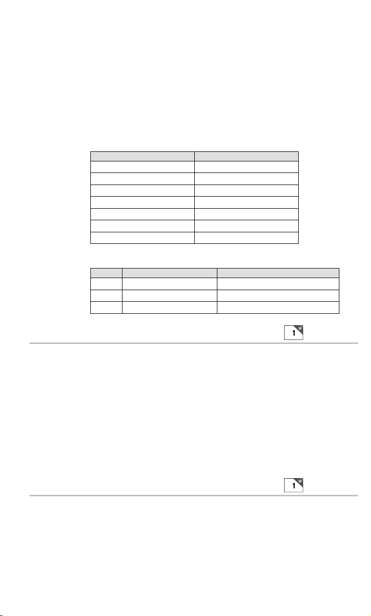
simply pressing the appropriate control key (without pressing the
ENTER key afterward). This allows for simple and fast scrolling by the
operator. The arrow keys, Begin, End, and Search are the specific keys
supported. The default setting is to require the ENTER key to be
pressed before data transmission.
• If you set this feature to 1 (YES), in order for the RF Terminal to
transmit the following values, the corresponding Control Key must be
the first key pressed in a data entry sequence. If it is not the first data
entered, the arrow key is ignored.
Control Key on RF Terminal Code transmitted to Host
Up Arrow FS (ASCII 28)
Down Arrow GS (ASCII 29)
Left Arrow RS (ASCII 30)
Right Arrow US (ASCII 31)
Begin ETB (ASCII 23)
End CAN (ASCII 24)
The message is sent to the host as:
Search VT (ASCII 11)
Bytes Function Value
1 RF Terminal ID 0-9, A-Z, a-z, - =
2 Data Transmitted ASCII Value from Table Above
Last Terminator of Message CR
LCD Display Mode
6 line display mode 0
4 line display mode 1
WARNING: All Terminals are shipped with 6 line displays and are configured
as 6 line display terminals; as shipped these terminals will not work in an existing
system programmed for 4 line display terminals. If you are currently operating a
system that uses 4 line displays and have not changed your program to utilize the
6 line display terminals, you MUST change the LCD Display Mode to 4 line
display in order for a Terminal with a 6 line displays to SIGN ON to your system.
The LCD Display Mode should only be changed if you are trying to use an
application program that only supports the 4 line formatting commands.
Other
LCD Backlight Display Mode
No 0
Yes 1
In all units shipped since December 2004, the Backlit Display is standard.
The default setting is for the LCD Backlight to be ON. As shipped the
Backlight Duration is 5 seconds.
2-7
Page 23

Backlight Duration
R
Always ON 0
Duration in # of seconds
1..2..5..-9
Other
This setting determines how long the Backlight Display is on at startup or
when triggered by pressing the F2 key. Always ON will create a drain on
your batteries and you can expect shorter battery life. The default setting is
5 seconds.
F
Skip Opening Screens
No 0
Go to Two-Way (SIGN ON) 1
Go to One-Way (ONE WAY) 2
Setup
• Many users want to skip the opening screens and go directly to SIGN
ON or ONE WAY communication once their programs are fully
operational. Selecting 1 or 2 will automatically take the operator to the
corresponding mode and into your application, skipping the usual
Mode Menu (SIGN ON?Y/N, SETUP?Y/N, ONE WAY?Y/N, SITE
TESTING?Y/N). If you want to return to the Mode Menu at any time,
simply press the F1 key.
If your skip the opening screen, you may want to quickly check the settings
of the Terminal without having to reset this parameter, so the Status Key
will display four lines as follows:
mm/dd/yy hh:mm
alkBAT-zz%
alk - when Alkaline batteries are specified in Battery
rch- when NiMH or NiCad batteries specified in Battery
zz=percent or battery life left in numbers i.e. 99, 50, 23
The next two lines show the following:
UC31003A IDx CHn RLx
6/6 SC=N RF=NN C=N
• The first character on the line is:
U for US/Canada Channel model
The next two characters “C3” is the board level.
• 1003A is the main processor's firmware version
• IDx , where x is the Terminal ID assigned (0-9,A-B, a-z, -=)
• CHn , where n is the Terminal's Channel in use (0-9)
2-8
setup
setup
Page 24
• RLx , where x indicates the ID of the relay (0-F) with which the
terminal was last communicating (N if it was not a relay, but a base)
• 6/6 is a 6 line terminal in 6 line mode; other possibilities are 6/4
SC=N indicates no Security Code is programmed (if Y, Security Code)
RF=NN refers to the radio processor firmware revision number
C=N indicates no Character mapping (if Y, beware, characters are remapped)
Press the STATUS key again to resume processing
Speaker and Headphone Volume Controls
By selecting Speaker in the keyboard Setup Mode, you get to the options to
control the Speaker/Beeper and Headphone volumes. If you are using
headphones, you will want set the Speaker volume to 0 to conserve batteries.
Volume settings possible are 0-9.The prompt for Speaker Volume is:
SPEAKER VOLUME
Enter 0-9 for Volume
Control
Current Value is: 5
The prompt for Headphone Volume is:
HEADPHONE VOLUME
Enter 0-9 for Volume
Control
Current Value is: 5
Speaker
Other
Automatic Check Back
This parameter should not be changed under normal circumstances. After
the host sends a prompt, the Terminal goes to sleep waiting on the operator
to key or scan input in response to the prompt. It waits until the Automatic
Shut Off time or until the operator responds. This parameter sets the time
that the Terminal stops waiting on input from the operator, discards the
current prompt, and goes back to the host to see if there is a change in
instructions. If no change, the host must resend the prompt again because
the Terminal has discarded the original prompt. The host now has the
opportunity to change a prompt. The time can be set in increments of 5
seconds, up to 495 seconds. The default value is 00. The values possible for
entry are 00-99. An entered 99 gives 99x5 seconds, or 495 seconds between
check backs. The Terminal sends back an ASCII 07 for the data back to the
host (ID ASCII 07 CR). This parameter's prompt is:
AUTOMATIC CHECK BACK
Key 00-99.
Current Value: 00
2-9
Page 25

Code 3 of 9 (Code 39)
B
Enable Code 3 of 9 0
Disable Code 3 of 9 1
Enable Full ASCII Code 39 2
Disable Full ASCII Code 39 3
Enable Code 39 Accumulate Mode 4
Disable Code 39 Accumulate Mode 5
Enable Start/Stop character transmission 6
Disable Start/Stop character transmission 7
Enable Mod 43 Check Digit 8
Disable Mod43 Check Digit 9
Enable Check Digit transmission A
Disable Check Digit transmission B
Caps Lock ON C
Caps Lock OFF D
• The Start and Stop character for Code 39 is the * character. Settings 6
and 7 determine whether or not those characters are transmitted to the
computer along with the data. For example, at setting 6, the data of
1234 would be transmitted as *1234*. Transmitting the start and stop
characters can be useful if you need to differentiate between data that
comes from a bar code versus data coming from the keypad.
• Enabling use of the Mod 43 check character requires that the last
character of your bar code conform to the Mod 43 check character
specifications. See Appendix E; Code 39 for more information. Enable
transmission (A) will send the check digit data along with the rest of the
bar code data to your computer. To use A, you must also be using 8.
ar
Codes
• Caps Lock ON causes lower case letters read as data to be transmitted
to the computer as UPPER CASE, and upper case letters to be
transmitted as LOWER CASE. Numbers, punctuation and control
characters are not affected. Caps Lock OFF means that letters will be
transmitted exactly as read. This setting applies to all bar code types.
• See Appendix E; Code 39 for more information regarding Accumulate
Mode.
2-10
Page 26

UPC/EAN
B
Enable UPC/EAN 0
Disable UPC/EAN 1
Enable UPC/EAN Supplements 2
Disable UPC/EAN Supplements 3
Enable transmission of UPC-A NSC or EAN 13 1st 2
digits
Disable transmission of UPC-A NSC or EAN-13 1st 2 digits 5
Enable transmission of UPC-A and EAN-13 check digit 6
Disable transmission of UPC-A and EAN-13 check digit 7
Enable transmission of UPC-E NSC and EAN-8 1st digit 8
Disable transmission of UPC-E and EAN-8 1st digit 9
Enable transmission of UPC-E and EAN-8 Check digit A
Disable transmission of UPC-E and EAN-8 check digit B
UPC-E0 Compressed C
UPC-E0 Expanded D
EAN-8 observing 9&A E
EAN-8 forced to transmit 8 digits always F
4
Codes
• Use setting 2 to enable reading of the 2 and 5 digit UPC/EAN supplements
commonly found on magazines and paperback books as well as the
Extended Coupon Codes. Using this setting force left to right reading of
UPC codes to assure that the supplement code is not missed.
• ISBN (International Standard Book Numbering) bar codes are EAN-13
with a 5-digit supplement. If the “Bookland” bar code uses 978
(books) or 977 (periodicals) as the first three digits, then the RF
Terminal can transmit it in the ISBN format. The settings for this are
found under the Laser Options parameter. To enable transmission of
the ISBN format, set the Laser Options parameter to D. To return to
the default of normal EAN-13 transmission, set it to C. For details on
ISBN, see Appendix J, UPC/EAN.
ar
• Use setting 4 and 9 to enable transmission of the NSC character to your
computer. The Number System Character is the leading character in
the bar code. For details, see Appendix J, UPC/EAN.
• Use setting 6 and A to enable transmission of the check digit character
to your computer. The check digit is the last character and is based
upon a calculation performed on the other characters.
• Setting C transmits UPC-E0 bar codes as is; setting D transmits them
with inserted zero’s to make them the same length as a UPC-A bar
code. A NSC of 0 is assumed. It is possible to read UPC-E1 bar codes;
by default this option is disabled. Do not enable UPC-E1 if you plan
on reading EAN-13 bar codes; you may experience partial reads when
reading EAN-13. The UPC-E1 option is set in the 2 of 5 Code
2-11
Page 27

parameter. To enable UPC-E1 reading, set the 2 of 5 Code parameter
B
to 8. To turn off UPC-E1 reading, set it back to the default of 9.
• If you prefer to transmit UPC-E bar codes in a 6-digit format while EAN-
8 is transmitted in its original 8-digit format use setting F. This will
allow you to use settings 9 and A and still transmit EAN-8 as 8 digits.
• UPC-A can be transmitted in EAN-13 format by adding a leading 0
(USA county code) to the UPC-A data. This setting is found in the
Laser Options parameter. To transmit in EAN-13 format, set the
Laser Options parameter to F. To return to the default (UPC-A
transmitted in original format) set it to E.
Code 128
Disable Code 128 0
Enable Code 128 1
Enable UCC/EAN-128 2
Disable UCC/EAN-128 3
Enable Storage Tek Code (TriOptic Code 39) C
Disable Storage Tek Code (TriOptic Code 39) D
Bar Code ID’s transmitted E
Bar Code ID’s not transmitted F
• UCC/EAN-128 is a subset of Code 128 that follows certain
specifications regarding character content, length and check digits.
Enabling UCC/EAN-128 (2) causes the RF Terminal to look for a Code
128 bar code that begins with the Code 128 F1 (Function 1) character.
See Appendix H: Code 128 for more details.
ar
Codes
• The StorageTek Tape Label code is a proprietary variation of Code 39
code used for the storage of computer data tapes. Enabling the tape label
code (C) does not disable reading of Code 128 or Code 39 bar codes.
• Bar Code ID’s are characters assigned to each bar code type to identify
that particular type of code. These Bar Code IDs can outputted as prefix
to the bar code data to identify what type of bar code you are using.
The Bar Code ID’s are assigned as follows:
Bar Code ID Bar Code ID Bar Code ID Bar Code ID
Codabar a 2 of 5 f UPC-E (1) o LabelCode 4 y
Code 39 b Code 128 g EAN-8 p LabelCode 5 z
UPC-A c Code 93 i RSS-14 r
EAN-13 d MSI j StorageTek s
I 2of5 e UPC-E(0) n Plessey x
The ID character is transmitted in front of the bar code data.
2-12
Page 28

Codabar
B
B
Enable Codabar 0
Disable Codabar 1
Enable CLSI Codabar 2
Disable CLSI Codabar 3
Disable Start/Stop character transmission 4
Enable Start/Stop character transmission 5
• CLSI is a form of Codabar often used by libraries.
• Setting 5 will transmit the Codabar start and stop characters with the bar
code data to your computer. If you are varying the start and stop characters
to differentiate between different labels, transmitting the start and stop can
be helpful. See Appendix G; Codabar for more information.
ar
Codes
2 of 5 Code
Enable Interleaved 2 of 5 0
Disable Interleaved 2 of 5 1
Enable Interleaved 2 of 5 check digit 2
Disable Interleaved 2 of 5 check digit 3
Enable check digit transmission 4
Disable check digit transmission 5
Enable Standard 2 of 5 6
Disable Standard 2 of 5 7
Enable UPC- E1 8
Disable UPC- E1 9
Normal Code 39 decode (Laser scanners) B
Loose Code 39 decode (for use with LZ400 thru windshields) C
Looser Code 39 decode (for use with LZ400 thru windshields) D
• Setting 2 requires that the last digit in your bar code conform to the
specifications for the 2 of 5 check digit calculation. See Appendix I; 2
of 5 Code for more information.
• Transmission of the check digit (5) requires the use of setting 2 and will
transmit the check digit along with the bar code data to the computer.
• Setting B pertains to the decoding algorithms used by the RF Terminal
when using a Laser Scanner. In most cases, this should be left at the
default B setting.
ar
Codes
• If scanning VINs (Code 39) through windshields with a laser scanner,
(applies to the LZ400 only) try setting this parameter to C or D. Try D
first. If you get substitutions, try C.
2-13
Page 29
2 of 5 Length
B
B
Default setting 06
Valid entries 00-98
To read variable length 2 of 5 codes 00
• 2 of 5 is so susceptible to misreads that the RF Terminal adds an additional
safeguard - it can be configured to look for fixed-length data only.
• The default setting of 06 causes the RF Terminal to read only 2 of 5
codes that are 6 digits in length. To set the RF Terminal to read a
different length, scan any two-digit number from the bar pad table. For
example, to change the RF Terminal to accept an 8-digit bar code, scan
0 then 8 from the bar pad table. 2 of 5 code must always be an even
number of digits so the length setting must always be an even number.
• Reading variable length I 2of5 or 2 of 5 codes is to be avoided if at all
possible. The 00 setting is supplied for the purposes of reading codes
of unknown length, counting the digits and setting the length to the
proper number.
ar
MSI and Plessey
Disable MSI 0
Enable MSI, 1 Mod 10 check digit 1
Enable MSI, 2 Mod 10 check digits 2
Enable MSI, 1 Mod 11/ Mod 10 check digit 3
Transmit no check digits 4
Transmit 1 check digit 5
Transmit 2 check digits 6
Enable Plessey bar code (mutually exclusive with MSI) 7
Enable LabelCode5 (mutually exclusive w/MSI & Plessey) 8
Enable LabelCode4 (mutually exclusive w/all above) 9
Codes
• LabelCode5 and LabelCode4 are proprietary bar code types used by
Follet.
• If you have enabled the Mod 10 or Mod 11 check digits, they will be
transmitted along with your bar code data from the RF Terminal to your host.
• For more information regarding MSI or Plessey Code, see Appendix
K; MSI Plessey Code.
RSS-14
Disabled 0
14 digits with no identifiers, i.e. 10012345678902 1
14 digits + identifiers, i.e. ]e00110012345678902 2
14 digits + UCC-128 format, i.e. ]C110012345678902 3
2-14
ar
Codes
Page 30
• By default, standard RSS-14 is disabled, scan 1 to enable. We support the
B
standard and stacked versions of RSS-14 formats.
For more information on RSS-14, see the AIM website at
http://www.aimglobal.org/standards/symbinfo/rss_overview.asp
Code 93
Enable Code 93 0
Disable Code 93 1
Enable Full ASCII Code 93 2
Disable Full ASCII Code 93 3
• Code 93 is similar in character set to Code 39. See Appendix F; Code
93 for more information. Code 93 is not a commonly used bar code
symbology.
Preamble
Preambles are user-defined data that is attached to the beginning of data
(bar code or keyed) that is transmitted to the host by the RF Terminal. For
example, if you set a preamble of @@ and scanned bar code data of 12345,
@@12345 would be transmitted to the host.
• By default, the RF Terminal has no preambles configured. Preambles
can contain up to 15 characters scanned from the bar coded FULL
ASCII Menu. To set a preamble:
1. Scan the Preamble bar code or select Preamble from the
keypad menu.
2. Scan the desired characters (up to 15) from the FULL ASCII Menu.
Codes
Other
ar
3. Scan the SET bar code, or if using the keypad, press ENTER.
4. To clear the Preamble and return to the default (no Preambles
defined), scan CLEAR at step #2, and then continue with your
setup.
• You can use the Preamble to trim characters from the data you are
entering into the RF Terminal. You can trim from 1-15 characters from
the data by creating a preamble of:
~x
where ~ is ASCII 126 and x is a single hex digit 1-F (corresponding to
1-15). Data that is shorter than the trim amount is transmitted without
trimming. Preambles trim characters from the front of the data. Here
are some examples:
2-15
Page 31

Data Preamble Data Transmitted
123 XYZ XYZ123
12345678 ~3XYZ XYZ45678
12345678 ~9 12345678
12345678901 ~A 1
123456 ~5 6
Preamble trims leading characters
• Using the Bar Code ID feature and the Preamble, you can trim data
selectively, trimming characters only on the bar code type specified.
To use selective trimming, enter:
~bx
where b is the Bar Code ID character (see the Code 128 setup parameter)
and x is the number of characters to trim from the front of the data. For
example, ~b2~c1 says “trim 2 characters from Code 39 data and 1
character from UPC-A data”. Remember that the Preamble trims leading
data. This applies to One-Way and host prompted communication.
• Lastly, the Preamble can be used to check a minimum/maximum data
length for bar code data entered. To check for bar code length in the
Preamble enter:
where | is ASCII 124, nn is the two-digit minimum and mm is the two-digit
maximum. |0210 would check for a minimum of 2 characters and a maximum of 10. If you try to scan a bar code outside the minimum or maximum
lengths, no decode will result. Entering data by keypad is not affected.
|nnmm
Postamble
Postambles are user-defined data that is attached to the end of data (bar
code or keyed) that is transmitted to the host by the RF Terminal. For
example, if you set a Postamble of @@ and scanned bar code data of
12345, 12345@@ would be transmitted to the host.
• By default, the RF Terminal has no Postambles configured. Postambles
can contain up to 15 characters scanned from the bar coded FULL
ASCII Menu. To set a Postamble:
1. Scan the Postamble bar code or select Postamble from the
keypad menu.
2. Scan the desired characters (up to 15) from the FULL ASCII Menu.
3. Scan the SET bar code, or if using the keypad, press ENTER.
4. To clear the Postamble and return to the default (no
Postambles defined), scan CLEAR at step #2, and then
continue with your setup.
2-16
Other
Page 32

• You can use the Postamble to trim characters from the data you are
entering into the RF Terminal. You can trim from 1-15 characters from
the data by creating a Postamble of:
~x
where ~ is ASCII 126 and x is a single hex digit 1-F (corresponding to
1-15). Data that is shorter than the trim amount is transmitted without
trimming. Postambles trim characters from the end of the data. Here
are some examples:
Data Postamble Data Transmitted
123 XYZ 123XYZ
12345678 ~3XYZ 12345XYZ
12345678 ~9 12345678
12345678901 ~A 1
123456 ~5 1
Postamble trims trailing characters
• Using the Bar Code ID feature and the Postamble, you can trim data
selectively, trimming characters only on the bar code type specified.
To use selective trimming, enter:
~bx
where b is the Bar Code ID character (see the Code 128 setup
parameter) and x is the number of characters to trim from the end of
the data. For example, ~b2~c1 says “trim 2 characters from Code 39
data and 1 character from UPC-A data”. Remember that the Postamble
trims trailing data.
• Lastly, the Postamble can be used to check a maximum character
length for data entered. To check for length in the Postamble, enter:
|nnmm
where | is ASCII 124, nn is the two-digit minimum and mm is the twodigit maximum. |0210 would check for a minimum of 2 characters and
a maximum of 10 If you try to scan a bar code outside the minimum or
maximum lengths, no decode will result. Entering data by keypad is not
affected.
Characters
This setting allows the RF Terminal to output chosen ASCII characters in
place of the actual characters entered. For example, if you scanned the
number 1 (hex 31) and wanted the RF Terminal to output hex 92 instead,
you would enter 3192 for the Characters parameter. This would re-assign
the output characters, with the RF Terminal outputting hex 92 every time it
sees hex 31. To re-assign characters:
• Scan Characters
2-17
Page 33
• Scan up to seven 4-digit pairings where the first 2 digits represent the
D
hex number to replace and the second 2 digits represent the hex
number to insert. You can have up to seven character reassignments.
• Scan SET
You can eliminate the output of a character by using FF as the hex number to
insert. For example, if you wanted to eliminate all $, following the above
instructions, enter 24FF.
Beep Tone
Lowest 0
Low 1
Medium 2
High 3
Highest 4
No Beep Tone 5
Speaker
Batteries
Alkaline Batteries 0
Rechargeables 1
• In order to get an accurate Battery Status reading; you must select the
correct battery type. If you ordered NiMH batteries (part number L01)
with the RF Terminal, this will be set to Rechargeable before shipping.
• If you didn't order re-chargeable batteries, this shipped setting is
Alkaline. Battery Status can be displayed by pressing the STATUS key
on the RF Terminal keypad.
• Before you can recharge the batteries, this parameter must be set to
Rechargeables. Don't try to recharge alkaline batteries. They might
explode. This will void your warranty.
• If you decide to use rechargeables after ordering the RF Terminal
without rechargeables included, you must change this setting allow
recharging.
Date Format
ate/
Time
US Format 0
European Format 1
• The US format of mm/dd/yy is the default setting.
• If you switch formats, you must reset the date (SET DATE) in the new
format also.
2-18
Page 34
Set Date
D
Time
For correct date display, the 6-digit date must be set in the date format you
plan to use. By default the US terminals use the US date format of
dd/mm/yy. If you change the date format, you must re-set the date to
match the new format. For example, to set a date of January 20, 1999, you
would enter 012099 (US format) or 200199 (European format). The date
can be scanned in from the bar coded Setup Menu or entered from the RF
Terminal keypad. To display the date during operation, press the STATUS
key.
Set Time
The time is set using a 4-digit military hhmm format. For example, to set
the time to 3:08 p.m., you would enter 1508. The time can be scanned in
from the bar coded Setup Menu or entered from the RF Terminal keypad.
To display the time during operation, press the STATUS key.
Display of Year
2 digit 0
4 digit 1
• By default, the RF Terminal is configured to display and transmit the
year in a 2-digit format; i.e. 1999 would transmit and display as 99.
• Before you change the RF Terminal to display a 4-digit year, i.e. 1999,
make sure that the software receiving data from the RF Terminal is set
up to accept a 4-digit year.
ate/
Voice Message Partitions
Other
This parameter partitions the total amount of voice messages into different
message lengths. The default setting is:
303015
xx yy zz
where: xx is number of ½ second messages
yy is the number of 1-second messages
zz is the number of 2-second messages
The total time allotted must not exceed 75 seconds. To change the partitions, scan
or enter 6 digits total; 2 for the number of ½-second messages, 2 for the number
of 1-second messages and 2 for the number of 2-second messages. See the
default setting as an example.
WARNING: changing the Voice Message Partitions parameter after you
have recorded messages could result in having to re-record some of them;
they would still be there but longer messages may get cut up and shorter
ones combined.
2-19
Page 35
Shut Down Time
By default, if the RF Terminal is inactive (no keystrokes or scanning) for
more than 5 minutes, it will shut itself down in order to conserve batteries.
This includes SIGNING OFF if appropriate. To resume operation, you
must turn the RF Terminal back on using the ON/OFF key. To change the
amount of time the RF Terminal waits before shutting down:
• Scan Shut Down Time
• Scan two digits - the default is 05 (5 minutes)- to correspond to the
length of time in minutes. For example, 01 would be 1 minute.
If you want to prevent the RF Terminal from shutting off automatically at all, set the Shut Down Time to 00.
Other
Laser Scanner Options
None 0
Double Decode 1
4.5 second laser beam 3
Transmit EAN-13 normally C
Transmit EAN-13 in ISBN format D
Transmit UPC-A normally E
Transmit UPC-A in EAN-13 format (with 0 flag character) F
• By default, the RF Terminal has no special laser options set. If any of
the features below seem to fit your situation, set them appropriately.
Settings C through F are not laser-dependent and are for UPC/EAN bar
code types only. See the UPC/EAN parameter for more information
• Double Decode is there to minimize the possibility of misreads when
scanning very poor quality bar codes. This option forces the RF Terminal
to keep reading until it gets two results that are identical. This "double scan
checking" takes longer but will minimize misreads since it must get the
same result twice before considering it a "good" read.
• 4-second laser beam increases the amount of time the laser beam is
activated, giving the laser more time to try and read a code. This option is
useful for trying to read poor quality code. Using the 4-second laser beam
with long range lasers give the operator more time to aim the laser properly
at a distant bar code (usually using the "marker" beam). The default beam
time is 2 seconds.
Aiming Dot Duration
Other
Other
This parameter applies to the built-in internal laser as well as the LZ200 and
LZ400 tethered laser scanners. Before the laser beam spreads, you can create a
brighter aiming dot to be sure you are on the bar code you want to read. The
default is set to 00, no aiming dot. You can key in 01 through 99 which creates
an aiming dot in 1/10
th
second increments; i.e., 20 would be two seconds.
2-20
Page 36
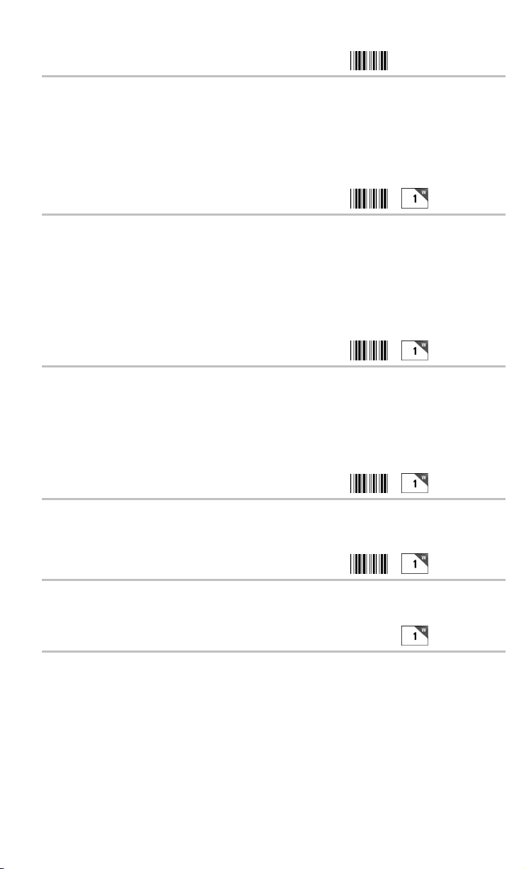
Reset
R
R
R
R
R
While in Setup Mode, DO NOT scan the RESET bar code unless you want to
set all of the RF Terminal setup parameters back to the factory default settings.
Scanning RESET will erase all changes you have made.
The following serial parameters Baud Rate, Parity, Data Bits, and Stop Bits apply only to
firmware updates and a portable printer such as the Cameo and QL3 printers.
Baud Rate
300 0
600 1
1200 2
2400 3
4800 4
9600 5
19,200
6
S232
S232
Parity
None 0
Even 1
Odd 2
• None is generally used with 8 data bits
• Even or Odd parity is generally used with 7 data bits.
Data Bits
7 bits 0
8 bits 1
S232
S232
Stop Bits
1 bit 0
2 bits 1
Protocol
None 0
XON/XOFF 1
Maintain backward compatibility for illegal statement handling E
Illegal statement handling for current versions F
• Settings 0 and 1 pertain to use of a serial Printer with your RF Terminal.
Use setting 1 for XON / XOFF if your serial Printer supports it. It DOES
NOT apply to the Cameo and QL3 Printers.
2-21
S232
Page 37
• Settings E and F pertain to the way the RF Terminal handles illegal
statements coming from the host computer. RF Terminal software
versions prior to 9.059 did not handle illegal statements the same way
as current versions. This setting is really only applicable if you had
written your host program to be compatible with RF Terminal
versions prior to RFT9059.
Base and Relay Setup
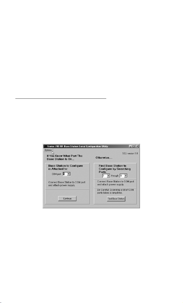
The Base and Relay Setup is only accessible via the RF 700 Configuration
Utility included on the Utilities CD that came with your RF Terminal. You can
also download the utility from our website at:
http://www.barcodehq.com/utilities/rfserial.exe
Using the RF 700 Configuration Utility
After you install the Configuration Utility from the CD or from the web,
make sure your Base or Relay Station is attached to one of the computer
COM ports using the 9 pin serial cable (F36) included with your system and
that the power supply (5v from Worth Data ONLY) is plugged in. A Base
Station will light the LED Green, while a Base jumpered as a Relay will
light a the LED Yellow, so be sure your unit is jumpered properly.
Start the RF 700 Configuration Utility.
If you know which COM port you are attached to, select that port in the
program, then click "
the program can find it for you. Enter the range of COM ports to search,
then click "
Find Base Station".
Continue". If you are unsure of the COM port number,
2-22
Page 38
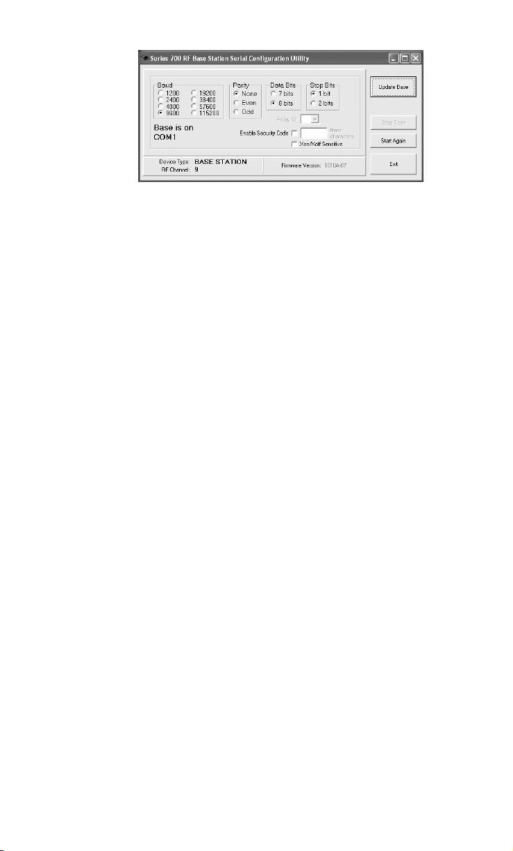
The program will look for the Base or Relay and determine its current
configuration. Once the program finds it, it will display the Device Type
(BASE or RELAY), the RF Channel (default is 01) and the Firmware
Version (xxxxx-pp). The first five characters are for the main processor's
firmware, which can be updated by you from the latest firmware always
available on our website. The last two last two characters are the firmware
version of the radio processor; this is not field updateable. If these two
characters don't show, (you see only xxxxx), it means your radio processor is
not responding and you need to call us to authorize a repair.
If you want to change any of the settings (Baud, Parity, Data Bits and
Stop Bits), you can do so by clicking the desired setting.
If you are configuring a Relay, the first Relay should be configured as
Relay ID "0", which is the default. If you have more than one Relay, then
select the desired Relay ID for this unit.
You can enable a Security Code for either a Base or a Relay. The Security
Code needs to be three characters and when enabled, requires anyone wanting
to make a change to the Base or Relay to enter this 3-character code.
"Xon/Xoff Sensitive" should be checked ONLY if your system has
XON/XOFF specified for handshaking on the serial port in use. Typically
in Windows, handshaking will be set to "None" and you should leave this
setting unchecked. See "Addressing a Terminal not Signed In" and "Base
Station Initialized Message" in Chapter 6 for details.
Once you have made any and all changes, click on the "Send Settings"
button. Your Base or Relay is now configured!
Testing the RF link between base station and host
Use the following command to test the transmission of data from host to
Base and back again to the host:
@@*Edataaaaaaaa<EOT>
where dataaaaaaaa is any string of data, terminated by EOT. This string
should be sent from the host to the Base Station. If the data is received by
the Base, it is echoed back to the host in the format:
2-23
Page 39

dataaaaaaaa<CR>
where dataaaaaaaa is the data string from the original transmission,
terminated by a CR (ASCII 13). This test verifies communication in both
directions (host to Base, Base to host).
• If the data isn’t echoed back, either your host COM port or the
Base Station has a problem.
• Once you know the Base Station is communicating with the host
correctly, compare the channel of the Base Station with the
channel of the Terminal. Use Site Testing to check the
communication of the Terminal to the Base and back. Stay close,
make sure no other Terminals are in use, and go to Site Test mode
on the Terminal. You should get 96-100% on first try. If you
don’t, it’s a good chance your radios need repair. Call Worth
Data for an RMA.
If you are using PICK or UNIX as your operating system, make sure the
Base Station is set to "XON/XOFF Sensitive".
2-24
Page 40

Chapter 3
Operational Theory
Before you jump in and start writing a complex host program, it might be nice to
be familiar with the theory behind the operation of your RF Terminal. The RF
Terminal has three different modes of communication:
• Two-Way Mode - the host program transmits requests for data to
the terminal via the Base Station. The RF Terminal transmits a
response back to the Base Station, which in turn sends the data on to
the host program. This is a truly interactive mode allowing you to
create flexible programs for a variety of applications that are
computer led and controlled.
• One-Way Mode - the RF Terminal transmits to the host with only
confirmation from the Base Station. The host program receives data
from the Base Station as it would any other serial device. The host
cannot send data to the terminal; it can only receive information.
• Site Test Mode – the Base Station and RF Terminal work together to
evaluate the site and determine the best location for the Base Station.
The site test evaluates the percentage of successful transmissions on
the first and second tries from any given area. The higher the
percentage, the more successful your communications will be from
that area. This helps you to identify problem areas before you
implement your RF Terminal system. At 30 ft., this is also the acid
test for suspected bad radios in a base or in a terminal.
Let’s start with a discussion of the basic theory behind a Two-Way RF Terminal
system.
How the Two-Way RF System works
Basic RF System communications…
The RF system consists of three components – Host Computer, Base Station
and RF Terminal. The Base Station connects to the Host Computer via the
serial port. The application running on the Host Computer sends a data
prompt to the serial port where the Base Station receives it. The Base
Station then transmits the data prompt via radio frequency to the intended
RF Terminal. The RF Terminal displays the data prompt on the display and
waits for the operator to enter the requested data. Once the operator enters
his data, the RF Terminal transmits the data to the Base Station, which in
turn passes it on to the Host Computer. The application on the host computer processes the information and sends a new data prompt out to the
Base Station and the whole process begins again.
3-1
Page 41

A little more in depth…
This RF system’s dialogue is Terminal initiated. The Terminal says, “I’m
here, give me something to do. The Worth Data RF system is different from
other systems in that our RF Terminal does not constantly “listen” for a data
prompt from the host. We decided to use a different approach that would
help to eliminate unnecessary radio traffic, conserve battery power, reduce
the size of the Terminal, and greatly simplify the base station's
logic/circuitry.
Here is how it works:
Each RF Terminal has a Terminal ID. When the RF Terminal powers up, it
asks if you want to SIGN ON? Pressing YES at the SIGN ON? prompt
causes the RF Terminal to transmit it’s Terminal ID and a byte of data indi-
cating to the Base Station that it wants to sign on to the system.
When you press YES to the SIGN ON prompt on the RF Terminal, the
Terminal will display the following message:
WAITING ON BASE TO ACKNOWLEDGE
This message is normal when first establishing communication and may
occur occasionally during normal operation.
When the Base Station receives a SIGN ON message from a RF Terminal,
the Base Station transmits the SIGN ON information to the host computer.
The host computer application can then do one of two things:
1. If it has something for the Terminal to do, it can send a prompt to the
Base, which in turn transmits it to the Terminal. The RF Terminal
receives the prompt, waits for the operator to enter the requested
data, and then transmits the data back to the Base Station.
2. If the host program does nothing within an allotted time, the
Terminal displays the message:
WAITING ON HOST PROMPT
Lets suppose that a RF Terminal and a Base Station have been processing
data by sending prompts and data back and forth as described in example 1.
The Base Station sends a data prompt to the RF Terminal, the RF Terminal
transmits the operator-entered data back to the Base Station. If the host
program has another prompt for the terminal, the Base sends it out, repeating the process above.
Suppose the host program does not have a prompt ready to send back to the
Terminal; the Terminal transmits its data to the Base Station but does not
receive a new data prompt. The Terminal then retransmits its data (it thinks
maybe the host didn’t receive it) and waits for a response.
Once the terminal has received a prompt back from the host, the time it took
the host to respond is sent to the Terminal. For all subsequent transmissions,
3-2
Page 42

the terminal goes to sleep until the time it took the last time for the host to
respond has expired; then the terminal wakes up and listens. If it has
nothing, it retransmits its data and waits for a response.
The original data transmission could have collided with another message, or
the Base could have received the Terminal's data but had not yet received
the host's prompt response. If the previous transmission got through, the
Base Station knows that the data is a retransmission rather than a new data
transmission so it sends a message to the Terminal telling it:
“I have nothing for you from the host, go to sleep”.
While in “sleep” mode, the Terminal “wakes” up at a random interval and
asks “do you have anything for me yet”, waiting for either a “go to sleep”
message or a new data prompt. After each delays, the Terminal displays:
WAITING FOR HOST PROMPT
If a Terminal receives no response at all from a Base Station (no data
prompt or “go to sleep” message), it retransmits its data and waits for a
response. If the Terminal gets no response after 10 re-transmissions, it
assumes it out of range from the Base Station with which it was
communicating, and attempts of establish contact with any Base Station. If
the Terminal can't contact any Base Station, it displays:
TRANSMISSION FAILED
HIT ANY KEY_
Pressing a key on the Terminal starts the re-transmission process over
again. The RF Terminal will try to retransmit its data, displaying the
TRANSMISSION FAILED message after every 10 unsuccessful tries.
Can I change a prompt after it has been sent?
Normally once the Terminal has received a prompt from the host, it goes to
sleep and waits (as long as it takes) for the operator to scan or key
something in response. The host cannot send another prompt without
creating a "Sequence Error." You might want to change the prompt or
locate a lost terminal with beeping.
There is a special setting in the RF Terminal Setup in which you specify the
time (between 5 seconds and 7 minutes) you want the Terminal to quit
waiting for input from the operator, blank the screen, send back a special
control character to the host program, display "Waiting on Host Prompt"
and wait for a prompt from the host application program; the host
application program can choose to send back different instructions or
simply repeat the previous prompt's instructions, (See Automatic Check
Back in the Programming Section).
3-3
Page 43

How the One-Way RF System works
The RF System can be used to perform “dumb” data entry to the computer –
you could even use Portkey to transmit the data through a serial connected
Base as though it has been entered from the keyboard. This is useful if you
want to enter data directly into an application. This type of data transmission
is called One-Way Mode. Once the RF Terminal transmits data to the Base
Station, the Base Station acknowledges receipt of the information by echoing
back the data to the Terminal that sent it, along with a beep. If the data
transmission did not make it through to the Base station after 10 tries, the RF
Terminal will give two long beeps and display the following message:
TRANSMISSION FAILED
TO RETRY, MOVE CLOSER
AND PRESS ENTER.
F1 TO EXIT.
One-Way mode also works well as a test program since it doesn’t require a
program running on the host computer or even that the Base Station be
connected to the host. To get into One-Way Mode:
At power up, the RF Terminal asks if you want to
SIGN ON?
KEY [YES/NO]?_
SIGN ON is for Two-Way communication only. Press NO, then press NO
again at:
SETUP MODE?
KEY [YES/NO]?_
When you see:
ONE WAY MODE?
KEY [YES/NO]?_
Press YES. If the Base Station already has other RF Terminals signed on in
Two-Way mode, you will not be allowed into the system. A Base Station
must be dedicated to one mode at a time.
If the Base Station is dedicated to One-Way mode, you will see the
following prompt on the RF Terminal display:
Data Received Was
Enter Data?
Since you have just started your One-Way session, there is no data to
display on line #2. Line #3 is now asking you to scan or key data into the
RF Terminal. If you are entering data from the RF Terminal keypad, you
must press the ENTER key to transmit your data. If the Base Station
receives the data, the RF Terminal displays the following prompt:
3-4
Page 44

Data Received Was
aaaaaaaaaaaaaaaaaa
Enter Data?
Where aaaaaaaaaaaaaaaaaa is the data received by the Base Station (and
transmitted to the Host Computer if connected). You can exit One-Way
Mode simply by pressing the F1 key on the RF Terminal keypad.
In One-Way Mode, the RF Terminal transmits its Terminal ID to the Base
Station but it does not pass it on to the Host Computer. If your application
on the Host Computer needs to know which RF Terminal data came from,
use the Preamble setup parameter to enter unique identifying information.
Data is also transmitted without a Terminator Character (like a CR or TAB
that is transmitted after the data); so if you need one, use the Postamble
setup parameter to add the appropriate character(s) after your data. For
more information on Preambles and Postambles see Chapter 2; RF System
Setup for details.
How Site Testing works
The RF Terminal uses Site Test mode to: 1) test the radios at short range,
(50 ft.) as an acid test for correct operation, and 2) to evaluate a specific site
for effective coverage. Because each operating environment is different, it
is almost impossible to predict the range without Site Testing.
Before you permanently install any hardware, you should perform a Site
Test to fully evaluate your planned area of operation. During the test the RF
Terminal is transmitting messages and waiting for acknowledgement from
the Base Station. (Since this US Terminal hops over 25 different
frequencies, the Site Test goes across all frequencies to make comparisons
valid; this takes about 10 seconds.) The Site Test evaluates the percentage
of successful transmissions. The higher the percentage, the more successful
your communications will be from that area. Site Testing does not require
your Base Station be attached to your Host Computer. All you need is your
Base Station, 5v power supply and RF Terminal. For detailed information
on how to perform a Site Test and use the results to determine the best
location for your Base Station, go to Chapter 4; Performance Issues.
3-5
Page 45

Page 46

Chapter 4
Performance Issues
Evaluating your area of planned operation
Since every operational environment is different, it is impossible for us to
tell you exactly what equipment you need and where you should put it to
achieve maximum performance from your RF System. However with 3000
ft. open area range, unless you are going through a lot of walls, you
probably won't care where the Base is located, and you probably will not
need a Relay.
Site Testing was developed so that the user could start with a minimum
system (RF Terminal and Base Station) and determine for themselves what
their realistic operating range is, what additional equipment they need, and
where to install their Base Stations to achieve optimum performance. Some
other manufactures require expensive Site Tests before you can even
purchase any equipment from them. Our Site Testing allows you the
flexibility to Site Test whenever you choose, whether it is before you install
your system or during operation to troubleshoot RF problems. Site Testing
is the most valuable tool you have to help you achieve an efficient RF
System with maximum range.
There is also some basic information about Radio Frequency itself that can help
you make smart choices about the location and composition of your system:
• Metal walls are almost impenetrable by RF. If your warehouse
computer is located in a metal shed, don’t locate the Base Station
inside with the computer. Locate the Base Station outside the metal
shed instead.
• The more walls you try to transmit through, the more the signal
breaks down. Walls that have metal studs (interior office walls)
and concrete walls with steel rebar slightly degrade the signal with
each wall you try to go through. Metal walls may require the use of
Relay Stations to achieve adequate coverage.
• Organic material absorbs RF energy. If you are trying to operate in
an area with lots of densely packed organic material (bags of beans or
corn), expect and plan for reduced operating ranges.
There are some additional measures (other than a Site Test) you can take
early on to maximize your range:
• Base Stations should be located at the center of the area of
intended coverage. If they are not located in the center, they should
be tilted in the direction of use.
• Raise the Base Station. Sometimes just raising the Base Station
12 feet will dramatically increase your operating range, especially
4-1
Page 47

in a warehouse or grocery store environment. Mounting the Base
Station on the ceiling with the antenna pointing down is the best.
Performing a Site Test
As we have said before, the Site Test is your most valuable tool for
evaluating your planned area of operation. All you need to perform a Site
Test is a RF Terminal, a Base Station and it's 5v power supply. There are a
few things you need to do though before you begin:
• Make sure all other Base Stations are turned OFF.
• Make sure that the Base Station and RF Terminal you are using
are set to the same channel. Base Stations and RF Terminals are
shipped from the factory set channel 0. If you need to change the
channel, see Appendix A; Channel and Jumper Changes.
The Base Station does not need to be connected to a host computer to do a
Site Test. Simply connect the Base Station to wall power using the 5v
power adapter. Locate the Base where you think you will have the best
range and power it up. Turn on the RF Terminal and press a key at the
opening screen.
• Press NO at the SIGN ON? prompt
• Press NO at the SETUP MODE? prompt
• Press NO at the ONE WAY MODE? prompt
• Press YES at the SITE TESTING? Prompt
If the Base Station is powered up, walk to the area where you want to
perform your first test, (start at 50 ft. or greater). When in position, stop and
look at the RF Terminal display. It should read:
Press Enter When
Ready, F1 to Exit
Press the ENTER key to start the test. During the test, (about 2 seconds),
hold still during the test – moving around can result in inaccurate results.
During the test the RF Terminal is transmitting many messages and waiting
for acknowledgement from the Base Station. During the test the following
message displays on the RF Terminal screen:
Site Testing in
Progress, Please
Wait…………..
Please Wait… will display on your screen until the test is finished. If it
takes more than a few seconds, there is something wrong. When the test is
finished, you will see the results displayed in the following format:
nn% Good
Press Enter When
Ready, F1 to Exit
4-2
Page 48
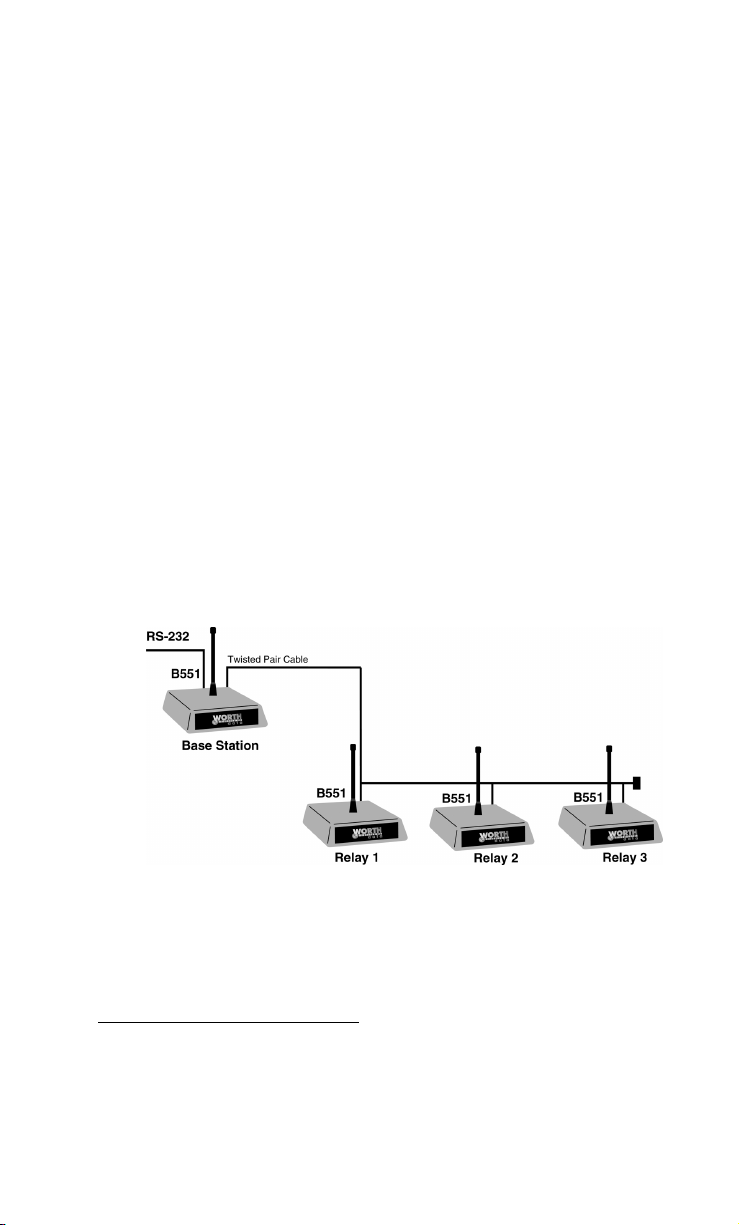
The first line shows the percent of successful transmissions. As long as you are
getting at least 90%, you will have excellent results in the location tested.
If you don’t get the minimum results shown above:
1. Try hanging the Base Station upside down or tilted toward the
area of usage – this alone can double the effective range.
2. If using a European terminal, try a different channel. You may
find less interference on another channel. There are several to
choose from, only try 1 or 2 others. This does not apply to the
US Terminal, because all channels use the same 25
frequencies, just in a different hopping order.
3. Try locating the Base Station closer to the area of difficulty.
Remember that moving the Base Station will require you to
recheck the other locations already tested.
4. If none of the above works, you will have to consider using a Relay.
Relay Stations
Keeping all of the above factors in mind, using Relay Stations can increase
your area of coverage by 5 times. Relays work like a remote antenna,
passing data to the Base Station via cable instead of radio frequency. Base
Stations are used as Relay Stations by changing the jumpers inside. See
Appendix A for details.
Relay Stations are attached to the Base Station using a cable that connects
from the Base’s RELAY port to the Relays’ RELAY port. When you order
a Relay Station, you receive a 3-foot test cable with it. Although Relay
Stations will increase your range of operation, they will also add about ½
second to the response time.
How Relay Stations work…
It helps to know how Relay Stations work before you add them to your
system. Although Relays increase your operational range, they also slow the
response time of your system. In order to use Relays, the Terminal must be
configured to acknowledge that Relays are present. This is done using the
4-3
Page 49

Relay Existence setup parameter. By default, the RF Terminal is not
configured to look for Relays. This setup parameter can only be accessed
via the RF Terminal keypad - it cannot be configured using the bar coded
RF Terminal Setup Menu. See Chapter 2; RF System Setup for details.
Once the RF Terminal is Relay-ready, it can use the Relay instead of the
Base Station to communicate. If a RF Terminal tries to transmit 10 times to
a Base Station without a response, it broadcasts a “who can hear me”
message. If both the Base Station and the Relay hear the message, whoever
answers back to the RF Terminal first becomes the point of contact for that
RF Terminal.
Once a RF Terminal has established communication with a Relay, it
addresses that particular Relay until another communication failure (10
transmissions with no response) occurs. If a Base Station is within hearing
distance of the RF Terminal, it will ignore messages meant for the Relay.
When a Relay receives data from a RF Terminal, it then transmits that data
to the Base Station over RS-422 twisted-pair cable. The Base Station in turn
transmits data (via cable) for that RF Terminal to the Relay, for subsequent
broadcast to the RF Terminal.
Relays are “dumb”. Relays do not know whether a transmission was
received by the Base Station or not, so it is up to the RF Terminal to
retransmit its data if it does not receive a message from the Host Computer
(via the Relay). The Relay can recognize data from the Terminal though
and if it receives 10 re-transmissions from the RF Terminal, the Relay
assumes that the Base Station cannot hear it and broadcasts the message:
RELAY n CANNOT BE
HEARD BY THE BASE
NOTIFY SUPERVISOR
PRESS ANY KEY
At this point, the RF Terminal puts out the “who can hear me” message.
The RELAY n CANNOT BE HEARD message usually indicates a
cabling problem and should be checked out immediately.
Sometimes a Relay gets a response from the Base Station that is partial data
or garbage. The Terminal retransmits its data since it has not received a new
prompt. If this occurs ten times, the RF Terminal broadcasts, “who can
hear me”. At this point the Relay is still functioning and answers the RF
Terminal’s call. Should the Relay respond to the RF Terminal first, the
whole sequence starts again. If the Relay again gets “garbage” messages
from the Base and the Terminal re-transmits 10 times, then the Relay
concludes that there is something wrong and broadcasts the RELAY
CANNOT BE HEARD message. This situation indicates that you may have
an electrical “noise” problem – check your cabling as well as any electrical
equipment that is in the area.
4-4
Page 50
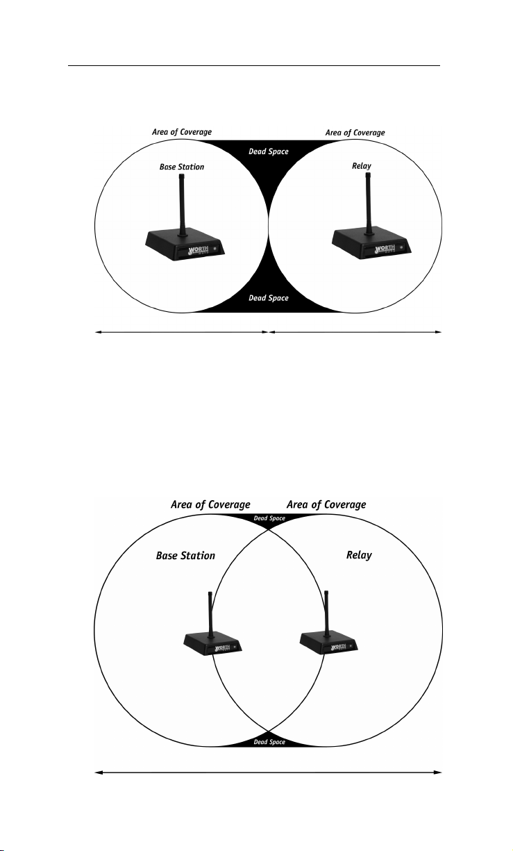
Determining coverage areas for Base Stations and Relays
As we said before, it is almost impossible to predict the effective RF
communications range in a given environment. The typical area of coverage
is a 1000 - 3000 ft. radius.
After a Site Test, if you have determined that you will need to add Relays to
cover the area you want to operate in, you will need to determine where to
place your Relay in relation to your Base Station. To effectively cover an
area, there must be overlap between the area covered by the Base Station
and the area covered by the Relay. The example below shows what can
happen with no area overlap:
As you can see, the only area adequately covered is in a path where the two
circles touch. The “dead space” is completely without coverage. Alternatively,
locating the Base Station and Relay as shown below results in better coverage:
4-5
Page 51

To Site Test a Relay, all other Relays and Base Stations must be turned off.
This is the only way to know for sure which Relay is responding. Alternatively,
perform the Relays’ test out of range of the other Relays and Base Stations.
Relay Installation
Relay Stations are connected to the Base by twisted-pair wire. See
Appendix B: Adding Relays for the pin outs and a testing plan.
Is radio traffic contention likely?
The radio traffic time is about 15ms per transaction. Radio time is not going
to be a gating factor, even with more terminals than the allowed 64 maximum.
The bottleneck could partially be the serial port baud rate in high volume
applications. The default baud rate is 9600 baud; you can increase this up to
115,200 baud, but the greater the baud rate, the less the RS-232 cable
distance allowable.
The gating factor for the application is almost always going to be the
application program. By splitting the application between two or more
work stations, each talking to a separate set of Terminals/Base Station, that
factor can be minimized.
4-6
Page 52

Chapter 5
Before you begin programming…
The RF Terminal operates in two basic ways:
One-Way communication, where all data transfer is initiated by the RF
Terminal. This is not very useful, because it has no editing or prompting.
The Base Station itself simply acknowledges the receipt of the data by
echoing it back to the Terminal. The host computer has no dialog
whatsoever with the Base Station or Terminal; it is simply used to take the
data coming from the Base through the serial port and do something with it.
Two-Way communication, where messages from the host user program
are sent to the Base Station (via the serial port), then from the Base Station
to the RF Terminal. The Terminal responds back to the Base with data and
its Terminal ID. The data is then transmitted from the Base to the host
computer where it is processed and the next command is sent out. Each RF
Terminal has a unique Terminal ID, allowing a single Base Station to
handle up to 64 Terminals.
Two-way dialog is established when a Terminal SIGNS ON to the RF
network. The host computer application waits until a Terminal SIGNS ON,
then begins its processing by sending the first prompt out to the Terminal via
the Base Station. If the Terminal does not receive a prompt from the host, it
goes into “sleep” mode, “waking up” and checking with the Base periodically
(see Chapter 3; Operational Theory for details) to see if it has any messages
waiting. This conserves battery power and reduces radio traffic.
Two-Way mode requires programming to communicate with the Terminal
where One-Way mode does not. We have tried to make it easy for the
programmer to communicate with the Base Station; no protocol or
handshaking is required. This type of communication is fine when the Base
is located only a few feet from the serial port it is connected to. If you are
locating your Base Station farther away, use shielded, grounded (bare wire
Pin 1 touching shield) cable, lower baud rates and possibly, line drivers for
very noisy environments. (Do not use Cat 5 wire for a serial cable).
Before you begin programming, there are some factors you should take into
consideration during the planning process.
• Plan for system failures. This includes hardware failures,
software failures and operator failures. In order to create an
efficient application, you must put some thought into what you will
do when different parts of the system fail.
• Look for All Errors. Be sure your program is trapping all possible
error conditions that the Base Station may return to you. The list
includes:
5-1
Page 53

Sequence Errors detected
Illegal Command detected
Base Station Initialized
Addressing a Terminal Not Signed In
Command without an ID
All of these error conditions are detailed in the next chapter. Don’t
forget to program for them; this is a common mistake. Failure to
trap them will give create very strange, unpredictable results.
Even though you don’t think your code will ever make a mistake, take
advantage of feedback that the Base Station provides. Failure to do so
is a common mistake that eventually results in serious program failure,
sometimes due to hardware problems that go undetected.
• Parse the Returned Strings thoroughly. Don’t assume anything
about the next response from the Base to your program and look
only for the partial string such as the ID only; parse the string
returned completely and be sure you are examining every
possibility. Failure to do so is a common mistake.
• Plan for expansion. You may start small (1 base/1 Terminal) but
try to create an application that will allow for easy expansion and
addition - especially of Terminals.
• Use the Demo Programs. The demo programs can at least allow
you to see how the system functions and whether you can
anticipate any system-wide problems. The demo programs should
also be used as a response-time benchmark.
Failure Planning
Hardware Failures
Let’s assume that each part of the system has failed. How are you going to
know what has happened and how are you going to recover?
• The most frequent failures are at the Terminal level. If a Terminal has
a hardware failure, it will not be able to SIGN OUT. It is possible for
the Terminal operator to press the ON/OFF key or the F1 key by
accident, forcing the Terminal to SIGN OUT - sometimes in the
middle of a transaction. This happens at battery-changing time also.
You need to plan for partial transactions - do you trash the data you do
have and start over, or pick up where you left off?
• Keep in mind that if a Terminal has SIGNED OUT in mid-
transaction, the Base Station clears any pending message for that
Terminal before it will allow it to SIGN ON again. Make
allowances to re-send messages or prompts that were cleared upon
SIGN ON if necessary.
5-2
Page 54

• If a Base Station has a hardware failure, neither the Terminal nor
the host computer will be able to communicate with it. When the
Base Station comes back on-line, it sends a “Base Station
Initialized” message back to the host, letting the host know that it
must re-initialize all Terminals and pick up any incomplete
transactions.
Operator Errors
•
Plan on your operator walking out of range and going to lunch in
the middle of a transaction. What do you do with the data you do
have, and where are you going to start up again?
• Let’s say your operator is SIGNED ON and decides it’s time to
take a break. Instead of pressing the F1 key to SIGN OUT, he
presses the OFF key. Pressing the OFF key is OK (it will SIGN
him OUT) but there is a delay until the SIGN OUT is
acknowledged. Because of the delay, the operator might think he
didn’t press the key hard enough and press it again - this time
actually powering down the Terminal before the SIGN OUT was
complete. If this happens, you need to plan to re-send the last
prompt to the Terminal when he SIGNs ON again.
5-3
Page 55

Page 56

Chapter 6
Programming for the RF Terminal
The four levels of programming support offered for the RF Terminal are:
1) Low Level ASCII sequences sent to and from the Base Station by
the user program reading/writing to the serial port.
2) Low Level ASCII sequences sent to and from the Base Station
using DLL for Windows for serial port reading/writing.
3) Active X drop-in components. Every necessary function is defined.
You just complete the code for each function.
4) TCP/IP Active X drop-in components used by the “Server”
computer to communicate with the “Client” computer that has the
Base Station(s) attached.
LOW Level ASCII sequences directly
Planning
Remember, plan for every error that the Base Station might return including:
Sequence Errors detected
Illegal Command detected
Base Station Initialization detected
Addressing a Terminal Not Signed In detected
Command without an ID
Programs can be written in any language that has access to the serial port
(reading/writing), regardless of the platform. No more than one Base
Station is allowed for each serial port.
Host to Terminal Programming
The basic format of a message that is transmitted from Host to Base to
Terminal is fairly simple:
Byte position Function Possible values
1 RF Terminal ID 0-9, A-Z, a-z, - =
2+ Command(s) **
Last Termination of message EOT (ASCII 4)
The RF Terminal ID is always the first byte and always only 1 character in
length. There are 64 different possible values - 0-9 , A-Z, a-z, - and =.
6-1
Page 57
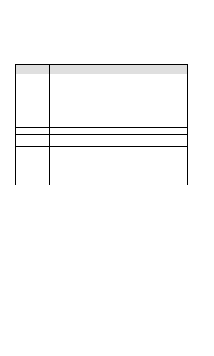
The Command(s) section of the message always starts with the second byte
and can consist of one or more commands - including data to be displayed
or voice messages to be broadcast.
The last byte is always ASCII 4 (EOT) to terminate the message.
Here is a listing of valid commands and examples:
Command
characters
*@
3@ Reinitializes Terminal #3
1@Bn Make Terminal #1 beep n (1-9) times
2@C0 * Clears the entire screen (4 lines or 6 lines) on Terminal #2. *See
0@C1 Clears line 1 on Terminal #0
1@C2 Clears line 2 on Terminal #1
2@C3 Clears line 3 on Terminal #2
0@C4 Clears line 4 on Terminal #0
3@C5 * Clears line 5 on Terminal#3 (if 6 line display), Clears all lines if 4
1@C6 * Clears line 6 on a 6 line display. Will do nothing on a 4 line
1@Dn Displays date and time on line n (1-4) in US (mm/dd/yy,
1@Vnn Play voice message #nn (01-99) on Terminal #1
1@Sdataxxxx Output dataxxxxxxx to serial port on Terminal #1 -max 231 chs
Command function
Reinitializes all terminals
more about 4 and 6 line displays on page 6-4.
line display. *See more about the two display types on page 6-4.
display. *See more about 4 and 6 line displays on page 6-4.
hh:mm:ss) or Euro (dd/mm/yy, hh:mm:ss) format on Terminal #1
A typical “prompt” command sequence follows the format below:
0@n,m,o,data
where
n
m
o
data
is the line number (1-4) you want the prompt displayed on
is the character position (1-20) where you want the
prompt displayed
is the character that determines whether the prompt is for
display only (0) or is waiting for data input (1) See the
table below for valid characters for this position.
is the data you want displayed
For example, the command @1,1,1, Enter Quantity would display Enter
Quantity starting at position 1 on line 1, then wait for the operator to enter
their data.
6-2
Page 58
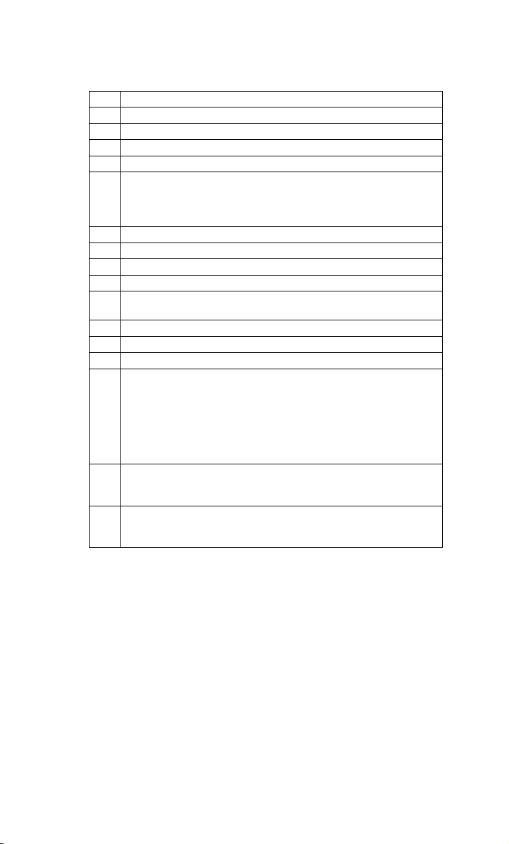
These are valid entries for the third position character:
0 No data input for this Command, Display ONLY
1 Data input required from the keypad or scanner
2 Only keypad input allowed, start un-shifted
3 Only keypad input allowed, start SHIFTED
4 Only scanner input allowed
5 Only accept YES (Enter key or C key) or NO (0 key or B key)
keypad response. (Terminal sends 1 for YES, 0 for NO). C and
B key are there to facilitate YES/NO keypad entry while
scanning with integrated laser.
A same as 1, but time stamped as prefix (hhmmss)
B same as 2, but time stamped as prefix (hhmmss)
C same as 3, but time stamped
D same as 4, but time stamped
E same as 4, but can press END key to break-out of scanner-
only input mode. Terminal ID + CR is sent to host
S SHIFTED keypad input or scanner input
p un-shifted keypad entry with no display (for passwords)
P SHIFTED keypad entry with no display (for passwords)
R Data input required from the RS-232 serial port (waiting for
serial input can be bypassed by pressing the ENTER key
which will send a NULL data string back to host computer.)
Uses for this are PDF 417 Serial Scanners, and the Cameo
Printer’s magnetic stripe input. A POS terminal becomes
possible. Scan the credit card and print the receipt, all on the
RF Terminal.
K Data input from an external serial keyboard that attaches to
the serial port. As data is keyed, the characters are displayed
on the RF Terminal LCD display.
M This command is for a printer initialization and magstripe input
on the Zebra Cameo printer equipped with the magstripe
option.
Here are some rules and useful tips for creating messages (one or more
commands per message):
• Re-initialize commands *@, or n@ (where n is the Terminal ID 0-
F) clear the buffer for terminal(s) in the Base Station. Following a
re-initialization, the host program should re-display of all the screen
data necessary to start the application.
• A message with multiple commands is legal and useful. For example,
the command “@1,1,0, PLEASE ENTER@2,1,1,QTY” would
display PLEASE ENTER on line 1, display QTY on line 2, and then
wait for data input. All 6 lines can be filled with one message.
• Messages can be a combination of multiple commands, (i.e. voice
messages, initialization, clearing lines, requesting data entry), up to
6-3
Page 59

231 characters in length. A message cannot though, contain an @S
command in combination with any other command. A message
also should not contain more than 1 request for data entry (third
character in command is 1). For example:
@1,1,1,ITEM@2,1,1,QTY
has two data entry “prompt” commands combined. If this message
were sent to the RF Terminal, the first data entry prompt
(@1,1,1,ITEM) would be executed, but any and all commands after
the first data entry prompt in that statement would be ignored
without warning – there will be no display or indication of an illegal
command.
The @S command (for serial output) statement cannot be
combined with any other command - even clear (@Cx) commands.
After a @S command is successfully completed, the Base Station
sends back to the host the RF Terminal ID followed by a CR
(ASCII 13). There is a 231 character limit on data for this
command. If you send a command of more than 231 characters,
you will get an Illegal Command returned, (ID ? CR). If you need
to send 300 characters of data, send the first part, wait for the
acknowledgement (ID CR), and then send the remaining part. If
you are using the @S command with a printer other than the Zebra
Cameo or QL3, you may have to change the Protocol parameter in
the RF Terminal to XON/XOFF. This will allow the RF Terminal
to deal with the character buffer limitations of your particular
printer. If you are using the O’Neil MicroFlash Printer, you must
send a NULL character before the valid data to wake up the
printer. See your printer manual for details and see Chapter 6 for
details on printer protocol.
• The @M command is similar to the @S command, except it can
be combined with other commands because it is a data entry
command too. This command is for a printer initialization and
magstripe input on the Zebra Cameo printer equipped with the
magstripe option. The format of the command is:
@Mdddatttta(EOT)
where dddatttta might be ! U1 MCR 80 T1 T2+ CR + LF
(Refer to the Cameo manual for the exact string sequence you need
to send. The above example sends over an 10 second request for
reading Track 1 and Track 2).
There is no reply to the host except the magstripe data. If the card
cannot be read, pressing the ENTER key on the Terminal will send
back ID+CR. This is the breakout method.
6-4
Page 60

This command must be the last in a series of commands. For
example, the following would be a typical multi-command
statement:
@C0@1,1,0,Swipe Card@M
where CR is ASCII 13
LF is ASCII 10
EOT is ASCII4
The statement causes the RF Terminal to transmit the string
"!U1 MCR 80 T2 CR LF" to the Cameo printer. The printer then
wakes up and blinks to indicate the magstripe input is ready to be
swiped; when the swipe is complete, the Terminal sends back the
data to the host computer as:
ID+T2:Data on Card+CR (the printer's CR LF stuff is stripped)
If the request is for Track 1 and Track 2, the data sent back is
ID+T1:data on 1+T2:data on 2+CR
! U1 MCR 80 T2 (CR)(LF)(EOT)
• Every statement must end with a data entry “prompt” command,
whether the statement is a single command by itself or several
commands combined together. Any illegal statement will be
ignored as a command but will be displayed on the addressed RF
Terminal display exactly as written. If no Terminal ID was
included in the statement, it will try to display the invalid statement
on ID 0. Once the ENTER key is pressed on the Terminal
displaying the invalid statement, the terminal sends the Base
Station a “?” character. The Base Station then in turn sends the
message n?CR (where n is the Terminal ID and CR is a carriage
return) back to the Host computer.
• The “Clear lines” command (@Cx) for the 4 line displays differ
slightly from the “Clear lines” command for the current 6 line
displays.
6-5
Page 61

The following table shows the programming differences for 4 lines/6 lines:
Command
@C0 Command did not exist Clears all lines on both a 4 line display
@C5 Cleared all lines on a 4
@C6 Command did not exist Clears line 6 on a 6 line display. Will
4 Line 6 Line
and a 6 line display.
line display
Clears line 5 on a 6 line display.
Clears ALL lines on a 4 line display.
not affect a 4 line display
• In order to maintain compatibility with 4 line display terminals in
an existing system, there is a new option in the RF Terminal Setup
for 6 line display terminals. The LCD DISPLAY MODE allows
the user to configure a 6 line display terminal as a 4 line display
(centering the data on the display and conforming to the old
programming command format, i.e. @C05 clears all lines). See
Installation and Setup for details on how to get into LCD
DISPLAY MODE.
• The SIGN ON character for a 6 line display RF Terminal operating
in 6 line display mode (see the previous point concerning LCD
DISPLAY MODE) is different than for a 4 line display. A 6 line
display terminal operating in 6 line mode signs on using ASCII 22.
If the 6 line terminal is configured for 4 line display, it signs on
using ASCII 15. This allows you to use both types of display in
the same system and be able to distinguish between the two
terminal types. See page 6-6 for more information on SIGN ON.
CAUTION: All 6 line display terminals are by default, configured
as 6 line display terminals and will try to SIGN ON using ASCII
22. If you are trying to SIGN ON to an existing 4 line display
terminal system that has not had any changes in its programming
to utilize the 6 line display terminals, the 6 line display terminal
will NOT BE ABLE TO SIGN ON. Make sure to reconfigure the
Terminal using the LCD DISPLAY MODE to operate as a 4 line
display terminal.
6-6
Page 62
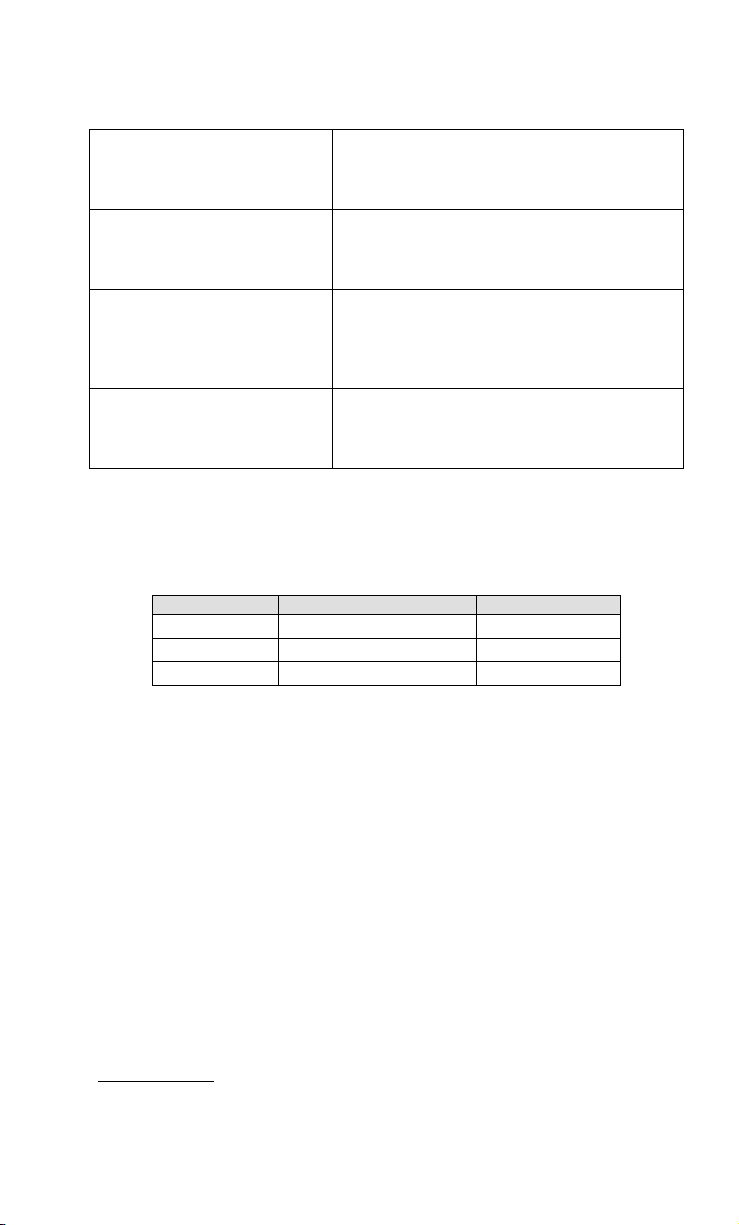
Here are some sample command statements utilizing some of the
programming tips offered above:
@2,1,1,ENTER ITEM NO Display ENTER ITEM NO on line 2, position 1
@V23@1,2,1,WRONG ITEM Play voice message 23, display WRONG ITEM
@C1@1,7,0,PICKING Clear line 1. Display PICKING at position 7 of
@1,1,1,ITEM@2,1,1,QTY
and wait for wait for data input. This is a valid
single command statement – it ends with a
data entry request.
on line1, position 2 and wait for data input. This is
a valid multiple command statement – it ends
with a data entry request.
line 1. This statement is illegal. To be a valid
statement, it must end with a data entry
request. For example:
@C1@1,7,0,PICKING@2,7,1,ITEM
Since only one command can be a “prompt” data
entry request, this is an illegal statement and
would be ignored as a command. It would be
valid if changed to @1,1,0,ITEM@2,1,1,QTY
Base Station to Host Formats
The basic format of a message that is transmitted from Base to Host is fairly
simple:
Byte position Function Possible values
1 RF Terminal ID 0-9, A-Z, a-z, - =
2+ Data Transmitted **
Typically, the Base Station is sending the “answer” to the hosts “question” for example, if a Base sent a host message to a terminal #2 that said:
Last Termination of message CR (ASCII 13)
2@1,1,1,ITEM NUMBER + EOT
The RF Terminal would display ITEM NUMBER on line 1, position 1 and
accordingly, the operator would then enter an item number by scanning or
using the keypad. The RF Terminal transmits the data entered -say it’s 123 to the Base Station, which in turn transmits the following to the host:
2123+CR
Where 2 is the Terminal ID, 123 is the data and CR is the termination, (the
plus sign is not transmitted).
Besides data, there are other messages that the Base Station will send to
the Host:
Serial Reply
After a Serial command (@S) has been successfully completed, the Base
Station sends to the Host the Terminal ID followed by a CR. Serial
6-7
Page 63

commands are typically used for attached serial printers. Serial commands
cannot be combined with other commands in a message to the Base
Station/Terminal. Remember, you can only send 231 characters (including
the ID + @S + EOT).
SIGN ON
To login to the host computer, the user presses a key on the RF Terminal at
power-up to get to the SIGN ON screen. As the user SIGNs ON, the Base
Station sends back the following SIGN ON message to the host:
Byte position Function Possible values
1 RF Terminal ID 0-9, A-Z, a-z, - =
2+ SIGN ON SYN (ASCII 22) if 6 line display
SI (ASCII 15) if 6 line display terminal
Last Termination of
After a terminal SIGNS ON, the host should be prepared to acknowledge
the SIGN ON and give the terminal instructions, such as:
configured as a 6 line display.
configured as 4 line display.
CR (ASCII 13)
message
Standby for Assignment, Press ENTER to acknowledge
Nothing to do, Press ENTER and See Supervisor
Pick Item 1234
If there is something for the Terminal to do, the host should send instruction
to the terminal (as in “Pick Item 1234” above). If there is nothing to do at
the time of SIGN ON, the host should acknowledge the SIGN ON and tell
the terminal to Stand By or See Supervisor (see lines 1 and 2 above). You
will notice that in lines 1 & 2 above, there is a request for the operator to
press the ENTER key. This is required for the message to be a valid
command - remember that all messages must end with a request for data
input. The host should then expect a response from the terminal of
Terminal ID + DATA (none if only pressing ENTER key) + CR.
SIGN ON is a good way for the terminal operator who has not received
instruction from the host for several minutes to determine if he is still
connected and if the host is still functioning. By SIGNing OUT and
SIGNing back ON, the operator should receive a message that there is
nothing to do. It is also a good idea for the host to keep track of elapsed
time that a terminal has not had a message sent out to it. The host should
then send a message periodically to re-assure the operator (remember to ask
him to press ENTER) that instruction is coming or tell him to see his
supervisor for re-assignment (or whatever makes sense for your
application).
6-8
Page 64
Ideally, if the operator is leaving the area (to go to lunch or move to another
building) before he is out of range of the network, he should SIGN OUT,
then SIGN ON upon his return.
A 6 line display terminal configured as a 6 line display (see Installation and
Setup for LCD DISPLAY MODE) sends ASCII 22 as its SIGN ON
character. A 6 line display terminal configured as a 4 line display will
transmit the ASCII 15 character for SIGN ON.
SIGN OUT
When a RF Terminal is powered down manually or the user presses the F1
key to exit data entry mode to go to one of the other modes (SETUP or
ONE WAY), the host receives the following SIGN OUT message:
Byte position Function Possible values
1 RF Terminal ID 0-9, A-Z, a-z, - =
2+ SIGN OUT SO (ASCII 14)
Last Termination of message CR (ASCII 13)
Base Station Error Feedback
The following are four different unexpected feedbacks that the Base Station
can send back to your program: (Be sure to look for each of them to be sure
your program doesn’t blow up at an unexpected time.)
Addressing a Terminal not SIGNed ON
If the host attempts to send a message to a terminal that is not SIGNed ON,
the Base Station sends back the following message to the host computer:
Byte position Function Possible values
1 RF Terminal ID 0-9, A-Z, a-z, - =
2+ Terminal NOT Signed In DC1(ASCII 17)
Last Termination of message CR (ASCII 13)
The ASCII 17 character can be changed to ASCII 16 for XON/XOFF
sensitive systems by changing the Base Station Setup. See Chapter 2; RF
System Setup for details.
If the Base Station receives five Addressing a Terminal not SIGNed On
messages in a row, it transmits the following message to the Terminal and
shuts down: (it will recognize a reinitialize command (*@EOT) from the
host though)
Base Shut Down
Due to Host Logic
Error
Check your program for the sequence error before starting again. The host
program will have to reinitialize the Base Station or you will have to cycle
6-9
Page 65
power on the Base Station and have the Terminal Sign On again in order to
continue.
Sequence Error Message
The host program must observe the one-for-one "host prompt/terminal
response" protocol at all times. The host cannot send a second data entry
prompt until it has received a response to the first data entry prompt. If it
does, this is considered a Sequence Error. If the Base Station receives a
command that is out of sequence, it sends the following message back to the
host:
Byte position Function Possible values
1 RF Terminal ID 0-9, A-Z, a-z, - =
2+ Sequence Error DC2 (ASCII 18)
If the Base Station receives 5 Sequence Error’s in a row, it transmits the
following message to the Terminal and shuts down: (the only host
command that it will receive is *@EOT)
Check your program for the sequence error before starting again. You will
have to reinitialize the Base Station by host program control (*@EOT) or
manually cycle power on the Base Station and have the Terminal Sign On
again in order to continue.
Last Termination of message CR (ASCII 13)
Base Shut Down
Due to Host Logic
Error
Illegal Command
•
When a terminal receives an illegal statement from the host, it will display
the entire statement on the terminal. Once the ENTER key is pressed on
the terminal, the terminal sends a “?” back to the Base Station.
Byte position Function Possible values
1 RF Terminal ID 0-9, A-Z, a-z, - =
2+ Illegal Command ?
Last Termination of message CR (ASCII 13)
For example, if Terminal #2 received an illegal command, the Base
station would transmit to the host:
2?CR
• If a command is sent from the host to the base station without a
valid terminal ID character, such as:
@1,1,1,Scan Serial Number
6-10
Page 66
since the command doesn’t specify which terminal it is meant for,
the base sends the following message back to the host:
?CR
*
• If the Base Station receives more than 231 characters, it treats that
statement as an Illegal Command. If it sees more than 231
characters 5 times in a row, it transmits the following message to
the Terminal and shuts down:
Base Shut Down
Due to Host Logic
Error
You can re-initialize the terminal by sending *@EOT or by
powering the base off and back on.
Automatic Check Back
When a terminal checks back in to see if there is a change in instructions,
the host can send back the same prompt or send back a new prompt. The
check back occurs according to the time specified in the Terminal's setup,
(specified in increments of 5 seconds). When a check back occurs, the
Terminal clears the screen of the current prompt, and sends back the
following message:
Byte position Function Possible values
1 RF Terminal ID 0-9,A-Z,a-z,-=
2+ Check Back BEL (ASCII 07)
Last Termination of message CR (ASCII 13)
Base Station Initialized Message
Whenever the Base Station is powered up, it sends a message back to the
host as follows:
Byte position Function Possible values
1 BASE ID
2+ Base Initialization DC3 (ASCII 19)
Last Termination of message CR (ASCII 13)
Since ASCII 19 is XOFF, the ASCII 19 character can be changed to ASCII
20 for XON/XOFF sensitive systems by changing the Base Station Setup.
See Chapter 2; RF System Setup for details.
The Base Station Initialized message is provided so that the host will
know that there has been a power interruption on the Base Station. When a
serial device powers up, the first byte transmitted is often garbage.
QBASIC handles the garbage character without incidence, but GWBASIC
does not unless ON ERROR GOTO is used to trap the error. Be aware of
this potential garbage-byte problem in your programming. To isolate and
6-11
* (Base ID is fixed)
Page 67
test for the problem, power up the Base without the serial cable connected.
After you power the Base up, plug in the serial cable. You will not see the
“Base Initialized” message but it should not matter when testing for the
garbage data.
If a terminal is signed-on to the system, and the base station is re-initialized,
the following message is sent to the terminal:
Base Reinitialized X
Cycle Power on RF
Terminal and Sign-on
again to Restart_
where X is either a P (base initialization was power-related) or H (base
initialization was host-related.
Control Keys for Possible Programming
There are some keys on the RF Terminal keypad that when pressed, can
transmit special ASCII characters back to the host program. This feature
might be used by a programmer to allow the operator to review transactions.
You can use these keys for special program functions, such as scrolling
thru data, backing up steps, jumping, finishing a process, etc The keys
are as follows:
Key Code transmitted to Host
UP ARROW key FS (ASCII 28)
DOWN ARROW key GS (ASCII 29)
LEFT ARROW key RS (ASCII 30)
RIGHT ARROW key US (ASCII 31)
BEGIN key ETB (ASCII 23)
END key CAN (ASCII 24)
The STATUS key is reserved to only display the Time and Date.
SEARCH key VT (ASCII 11)
The Control keys can be used without pressing the ENTER key by using the
Control Keys Only Terminal Setup parameter. See Chapter 2; RF System
Setup for details.
6-12
Page 68

LOW Level ASCII Sequences using a DLL
The DLL disk is included with every RF Terminal system. To install the
program, run the INSTALL.EXE program from Windows Explorer. The
program, PromptCOM comes in both 16 bit and 32 bit versions of a
Windows Dynamic Link Library (DLL) that allows programmers to easily
add the ability to send prompts and receive data from their RF Terminal via
the RF Base Station or direct serial link.
The Application Programming Interface (API) for PromptCOM consists
of the following functions:
InitComDLL Initializes the PromptCOM system
CloseComDLL Shuts down the promptCOM system and frees
resources without closing the parent application.
Setup Setup is used to configure the COM port
SendCommand This function both sends a command to the terminal
with the given ID
GetCommData This function returns the data entered at the remote
unit for that prompt
DataAvailable Use this function to check if there is data to process
before calling GetCommData
There are sample programs distributed on the diskette for Visual Basic,
Access and Delphi. There is also a Visual Basic code example that does not
require the DLL. Use the Help System as documentation and view the
README file for the latest changes.
PromptCOM/ActiveX
Drop-in components are tools that are added to your programming
environment "tool kit". There are a variety of different technologies around
for implementing a drop-in component such as VBX (for Visual Basic) and
VCL (for Delphi and C Builder) and COM (ActiveX). Only the ActiveX
variety are widely compatible with almost all development environments.
PromptCOM/ActiveX is a drop in COM component that allow
programmers to easily add the ability to send prompts to and receive data
from their R/F Terminal via an RF Base Station. It is compatible with
6-13
Page 69

Visual Basic, Visual C++, Delphi, and most other 32-bit development
platforms. See the help file for installation instructions.
Programming Considerations for Serial COM
Before making any method calls, make sure you :
• Set the COM port properties (device name, baud, parity, bits,) as
desired. Make sure the port is closed (call
making changes to any of the port settings.
CloseDevice) before
• Call the OpenDevice method. This activates the COM port used
by this instance of the WDterm control.
• Set the ActiveTerminal property to identify the terminal on which
you desire to operate. You can change the
time in order to direct commands to appropriate terminals.
ActiveTerminal at any
Test For Good Communication - Serial COM
Implement an event handler for OnTermBaseRegister that causes a beep or
displays a message when called. If communication between the host PC and
the base station is good, your event handler will fire when your program is
running and you power up an attached base station.
Multiple Base Stations
•
For installations using multiple base stations attached to a single host
PC (these were called "channels" in PromptCOM/DLL) simply add a
WDterm control to your application for each base station.
Terminal Tracking
•
Since you get one set of event handlers for each base station, you will
need some scheme for keeping track of where each terminal (up to 64
per base station) is in its transaction sequence. One possible solution is
to use a "state"variable for each terminal (perhaps stored in an array).
Test the state variable to determine the next prompt for any given
terminal. See the samples for more ideas.
• It is very important to keep track of "login status" for each
terminal. Every
event and a given terminal should not be allowed to
without an intervening
terminal without appropriate
1. A terminal going out of range and having its power cycled
before returning within range OR
2. Two (or more) terminals using the same ID (terminal ID
conflict).
SignOut event should have an associated SignIn
SignOut. Multiple SignIns from one
SignOuts indicate either:
6-14
SignIn twice
Page 70

Concepts - Serial COM
When you use drop-in components in your program you will follow the
standard object-oriented programming paradigm that uses properties,
methods, and events to implement the functionality of the drop-in
component.
• Properties are the various configuration variables used by the
drop-in component. An example of a property is the
ComDeviceName setting.
• Methods are function calls used to issue commands and access
features of the drop-in component. An example of a method is
sending an
• Events are function definitions placed in your application’s source
code. The function definitions in your source code are called Event
Handlers. The skeleton structure of the event handler’s source code
is automatically generated. The code in the Event Handler is called
("fired") by the drop-in component when a specific event occurs.
An example of an event is when a terminal returns data and the
OnTermData event is fired.
The details of how to access Properties/Methods/Events varies between
development platforms. Details of how it works in some of the most popular
platforms is illustrated in the samples included with the RF Utilities CD or
available for download from our website at:
Input command to the terminal.
http://www.barcodehq.com/wdterminal.exe
Properties - Serial COM
Properties are the various configuration variables used by the WDterm
control. They are directly assignable in your application (e.g.
"
WDterm.ActiveTerminal = 5") and can be set in your development
environment’s object browser.
Important: Except for
serial port to be "closed" before they can be changed. Use the
method before setting properties and then call
serial port.
Note that your development environment may show more properties for the
WDterm control than are listed here. This is normal. You may ignore
properties you see that are not listed here.
ActiveTerminal and Quiet, all properties require the
CloseDevice
OpenDevice to re-open the
6-15
Page 71

ActiveTerminal
Valid values: 0 -63
Definition: This is the terminal ID (0-63) to which method call
instructions are directed.
ComDeviceName
Valid values: COM1-COM16
Definition: This is the serial port that this instance of the
control will use. If you have more than one base
station, drop in another WDterm control and set its
ComDeviceName for your other COM port(s).
ComBaudValue
Valid values: 300, 600, 1200, 2400, 4800, 9600, 19200, 38400,
57600, 115200
Definition: This is the serial port speed setting and must match
the base station setting.
ComParity
Valid values: None, Even, Odd.
Definition: This is a serial port setting and must match the base
station setting. WDterm may allow other settings
but those listed here are the only ones compatible
with current version base stations.
ComDataBits
Valid values: 7, 8
Definition: This is a serial port setting and must match the base
station setting. WDterm may allow other settings
but those listed here are the only ones compatible
with current version base stations.
ComStopBits
Valid values: 1, 2
Definition: This is a serial port setting and must match the base
station setting. WDterm may allow other settings
but those listed here are the only ones compatible
with current version base stations.
6-16
Page 72

Quiet
Valid values: True, False
Definition: If
Quiet is set to True then any status and error
message generated by WDterm will be suppressed.
Methods - Serial COM
Methods are commands that you issue to the WDterm control. All of the
"
Inputxxx" commands cause the terminal to wait for operator input.
Note that your development environment may show more available methods
for the WDterm control than are listed here. This is normal. You may
ignore methods you see that are not listed here.
Important: When your application starts up, the serial port is "closed". You
must call
Except for the
property to identify the terminal to use.
OpenDevice before other method calls will work.
ReInitAll method, all methods use the ActiveTerminal
OpenDevice
Function: Opens the communications (serial) port. This must
be called before any of the methods described
below. Make sure to set all Properties as desired
CloseDevice
before calling this method (except
or
Quiet).
ActiveTerminal
Function: Closes the communications (serial) port. This must
be called before changing any of the Property
settings (except
ActiveTerminal or Quiet). When
your application starts up, the serial port is
"closed". You must call
OpenDevice before other
method calls will work.
InputAny
Parameters: line, position, prompt, shifted, timestamped
Function: This instructs the
ActiveTerminal to display the
prompt at line and position and wait for data to be
entered from either terminal keypad or scanner. If
shifted is set to "true", the terminal will start in
shifted mode. Timestamped appends a (hhmmss)
prefix to the returned data.
6-17
Page 73

InputKeyBd
Parameters: line, position, prompt, shifted, timestamped
Function: This instructs the
ActiveTerminal to display the
prompt at line and position and wait for data to be
entered from the terminal keypad only. If shifted is
set to “true”, the terminal will start in shifted mode.
Timestamped appends a (hhmmss) prefix to the
returned data.
InputScanner
Parameters: line, position, prompt, allowbreakout, timestamped
Function: This instructs the
ActiveTerminal to display the
prompt at line and position and wait for data to be
entered from the terminal scanner only. Setting
allowbreakout to true allow user to "break out" of
scanner only mode by pressing the end key on the
terminal. A termID+CR will be sent to the host.
InputYesNo
Parameters: line, position, prompt
Function: This instructs the
ActiveTerminal to display the
prompt at line and position and wait for a Yes
(Enter key or C key) or a No (0 key or B key) from
the terminal keypad.
Note: C and B keys are used to facilitate keypad
entry while scanning with the integrated laser.
InputPassword
Parameters: line, position, prompt, shifted
Function: This instructs the
ActiveTerminal to display the
prompt at line and position and wait for data to be
entered from the terminal keypad only. The entered
data is not displayed on the terminal.
InputSerial
Parameters: line, position, prompt
Function: This instructs the
ActiveTerminal to display the
prompt at line and position and wait for data to be
received through the terminal serial port. Waiting
for serial input can be bypassed by pressing the
enter key on the terminal which will send an empty
data string to the host (fires the
handler).
6-18
OnTermData event
Page 74

OutputSerial
Parameters: data
Function: This instructs the
ActiveTerminal to send data to the
terminal’s serial port. Data must be less than 231
characters in length for each call to
SendDisplay
OutputSerial.
Parameters: line, position, prompt
Function: This instructs the
ActiveTerminal to display the
prompt at line and position. Must be followed by an
"
Input" method call to take effect.
ClearScreen
Function: This instructs the ActiveTerminal to clear its
display. Must be followed by an "
Input" method
call to take effect.
ClearLine
Parameters: line
Function: This instructs the
ActiveTerminal to clear the
specified line on its display. Must be followed by
an "
Input" method call to take effect.
SendDate
Parameters: line
Function: This instructs the
ActiveTerminal to display date
and time on the specified line number. Must be
followed by an "
Beep
Input" method call to take effect.
Parameters: count
Function: This instructs the
ActiveTerminal to beep count
times. Count may be a value from 1 to 9. Must be
followed by an "
Input" method call to take effect.
6-19
Page 75

PlayVoice
Parameters: msgnum
Function: This instructs the
ActiveTerminal to play voice
message number msgnum. Msgnum may be a value
from 1 to 99. Must be followed by an "
Input"
method call to take effect.
ReInit
Function: This instructs the ActiveTerminal to re-initialize.
Must be followed by an "
Input" method call to take
effect.
Base Stations use the message "Buffer
Reinitialized..." to indicate a single terminal reinitialization.
ReInitAll
Function: Instructs all attached terminals to re-initialize.
Events - Serial COM
WDterm events occur when a specific condition is met. When an event is
"fired", an event handler function in your application is called.
Though the details of exactly how it is done varies from one programming
environment to the next, the source code skeletons for the various event
handlers are automatically generated and inserted into your source code for
you. See the samples for more specific information.
Each event passes relevant information to your event handler function. The
only event that does not pass any data is
pass at least the Terminal ID on which the event occurred.
also passes the data that was keyed or scanned into the terminal.
OnTermBaseRegister. All others
OnTermData
Terminal ID is always passed as 0-63. A Terminal ID value of 99 indicates
an error.
Once you have the event handler skeletons, you can proceed to add
whatever functionality you desire to each event.
You must call the
OpenDevice method before any events can be fired.
OnTermBaseRegister
Event: An attached base station has successfully powered
up and communicated with the host computer via
the serial connection.
6-20
Page 76

OnTermSignIn6
Data passed: terminal
Event: A six-line terminal has signed in. Terminal ID is
passed in terminal.
OnTermSignIn4
Data passed: terminal
Event: A four-line terminal has signed in. Terminal ID is
passed in terminal.
OnTermSignOut
Data passed: terminal
Event: A terminal has signed out. Terminal ID is passed in
terminal.
OnTermData
Data passed: terminal, data
Event: A terminal has sent data in response to an Input
method call.
OnTermNotSignedIn
Data passed: terminal
Event: A command has been sent to a terminal that is not
signed in.
OnTermSequenceError
Data passed: terminal
Event: The one-for-one host prompt/terminal response
protocol has been violated. The host cannot send a
second Input command until it has received a response
from the first
Input command. If a base station
receives 5 sequence errors in a row, a Host Logic error
is generated and the base shuts itself down.
While PromptCom/ActiveX will intercept and
prevent most logic errors, they are still possible so
you should implement this event handler!
OnTermIllegalCommand
Data passed: terminal
Event: An illegal command has been sent to a terminal.
PromptCom/ActiveX is designed to prevent illegal
commands but software is not always perfect and
6-21
Page 77

we may not have imagined all the ways in which
our customers will want to use it!
OnTermUpArrow
Data passed: terminal
Event: The up-arrow button has been pressed on a
terminal. You must issue another
Input method call
before WDterm can respond to another keypress
on the terminal.
OnTermDownArrow
Data passed: terminal
Event: The down-arrow button has been pressed on a
terminal. You must issue another
Input method call
before WDterm can respond to another keypress
on the terminal.
OnTermLeftArrow
Data passed: terminal
Event: The left-arrow button has been pressed on a
terminal. You must issue another
Input method call
before WDterm can respond to another keypress
on the terminal.
OnTermRightArrow
Data passed: terminal
Event: The right-arrow button has been pressed on a
terminal. You must issue another
Input method call
before WDterm can respond to another keypress
on the terminal.
OnTermBeginKey
Data passed: terminal
Event: The BEGIN button has been pressed on a terminal.
You must issue another
Input method call before
WDterm can respond to another keypress on the
terminal.
OnTermEndKey
Data Passed: terminal
Event: The END button has been pressed on a terminal.
You must issue another
Input method call before
6-22
Page 78

WDterm can respond to another keypress on the
terminal.
OnTermSearchKey
Data passed: terminal
Event: The SEARCH button has been pressed on a
terminal. You must issue another
before WDterm can respond to another keypress
on the terminal.
Input method call
PromptNET TCP/IP Active X Controls
PromptNET/ActiveX is a drop in COM component that allows
programmers to easily add the ability to send prompts to and receive data
from their R/F Terminal via an RF Base Station across a TCP/IP network
connection.
PromptNET requires a "Client" computer on a TCP/IP network (to which
up to 4 serial Base Stations can be attached) and a "Server" computer
visible on the network to the Client.
The client computer runs the PromptNET Client Utility program as a
background task. The server computer runs your application which uses the
PromptNET ActiveX component to communicate with the Client.
The ActiveX component is compatible with Visual Basic, Visual C++,
Delphi, and most other 32-bit development platforms. The client program
requires Windows 98 or later. See the help file for installation instructions.
Programming Considerations
Network Setup
•
The network settings on both client and server must support
TCP/IP communications.
• It is critical that the client and server computers are "visible" to
each other across your network. Both computers must have an IP
address in the same subnet. The server requires a static IP address
while the Client can either have a static address or use an assigned
IP address via a DHCP server or equivalent. Refer to your
Windows networking administration utility in the Control Panel to
configure computer IP address settings.
• PromptNET uses ports 54123 (server) and 54124 (client).
• You can link server and client through a dial-up or DSL internet link
as long as the server has a static IP address and your router passes
the above ports.
6-23
Page 79

• If you are unsure of how to set up your IP configuration properly,
refer to your network administrator for help.
Client Utility
•
Make sure the Client Utility is properly installed on the client
computer and communicating with at least one Base Station. Test
the Client by cycling power on the Base Station. You should see a
"Base SignOn" message in the monitor window.
Server Communications
•
Run the Server Test Utility on the server computer. Now go to the
client computer, set the IP address for the server computer and a
unique "Base Name" for the Client Utility and attempt to connect
to the Server Test Utility. If the Client Utility connects, you are
configured properly. Go to the server computer, shut down the
Server Test Utility and begin work on your PromptNET server
application.
• For Client/Server communications, the Client Utility is required to
be running on the PC that the serial Base Stations are attached to.
• Before making any WDIPterm method calls in your application,
make sure to set the
ServerOn property to "true".
Test For Good Communication
•
Implement an event handler for OnTermBaseRegister that causes
a beep or displays a message when called. If communication
between the host PC and the base station is good, your event
handler will fire when your program is running and you power up
an attached base station.
Multiple Base Stations
•
For installations using multiple base stations attached to a single
client PC, simply use the four "channels" provided by the Client
Utility program.
Terminal Tracking
•
Since you get only one set of event handlers, you will need some
scheme for keeping track of where each terminal (up to 64 per base
station, up to 4 base stations per client) is in its transaction
sequence. One possible solution is to use a "state" variable for each
terminal (perhaps stored in an array). Test the state variable to
determine the next prompt for any given terminal. See the samples
for more ideas.
• It is very important to keep track of "login status" for each terminal.
Every SignOut event should have an associated SignIn event and a
given terminal should not be allowed to SignIn twice without and an
6-24
Page 80

intervening SignOut. Multiple SignIns from one terminal without
appropriate SignOuts indicate either:
1. A terminal going out of range and having its power cycled
before returning within range OR
2. Two (or more) terminals using the same ID (terminal ID
conflict).
Concepts - TCP/IP COM
Drop-in components are tools that are added to your programming
environment "tool kit". Only the ActiveX variety are widely compatible
with almost all development environments. When you use drop-in
components in your program you will follow the standard object-oriented
programming paradigm that uses properties, methods, and events to
implement the functionality of the drop-in component.
Properties are the various configuration variables used by the drop-in
component. An example of a property is the
Methods are function calls used to issue commands and access features of
the drop-in component. An example of a method is sending an
command to the terminal.
Events are function definitions placed in your application’s source code.
The function definitions in your source code are called Event Handlers. The
skeleton structure of the event handler’s source code is automatically
generated. The code in the Event Handler is called ("fired") by the drop-in
component when a specific event occurs. An example of an event is when a
terminal returns data and the
OnTermData event is fired.
ServerOn setting.
Input
The details of how to access Properties/Methods/Events varies between
development platforms. Details of how it works in some of the most popular
platforms is illustrated in the samples included with the RF Utilities CD or
available for download from our website at:
http://www.barcodehq.com/wdterminal.exe
Properties - TCP/IP COM
Properties are the various configuration variables used by the WDIPterm
control. They are directly assignable in your application (eg.
"WDIPterm.ServerOn = true") and can be set in your development
environment’s object browser.
Note that your development environment may show more properties for the
WDIPterm control than are listed here. This is normal. You may ignore
pro-perties you see listed in your development environment that are not
listed here.
6-25
Page 81

ServerOn
Valid values: True, False
Function: Set to True to enable the server. Set to false to turn
the server off. You should leave this off unless your
program is actually running. Setting it to True at
design-time can cause problems.
Quiet
Valid values: True, False
Function: If
Quiet is set to True then any status and error
message generated by WDIPterm will be
suppressed.
LogFile
Valid values: blank or a valid file name
Function: If the file does not exist it will be created. If it
exists, it will be appended to. If
LogFile is blank,
no log file is maintained.
ClientList
Valid Values: Read Only.
Function: Returns a formatted string listing all attached client
BaseNames and associated IP numbers. Format is
"basename CR/LF ip address CR/LF basename…".
Methods - TCP/IP COM
Methods are commands that you issue to the WDIPterm control. All of the
"
Inputxxx" commands cause the terminal to wait for operator input.
Note that your development environment may show more available methods
for the WDIPterm control than are listed here. This is normal. You may
ignore methods you see that are not listed here.
InputAny
Parameters: basename, channel, terminal, line, position,
prompt, shifted, timestamped
Function: This instructs the terminal attached to client
basename on channel to display the prompt at line
and position and wait for data to be entered from
either terminal keypad or scanner. If shifted is set to
"true", the terminal will start in shifted mode.
Timestamped appends a (hhmmss) prefix to the
returned data.
6-26
Page 82

InputKeyBd
Parameters: basename, channel, terminal, line, position,
prompt, shifted, timestamped
Function: This instructs the terminal attached to client
basename on channel to display the prompt at line
and position and wait for data to be entered from
the terminal keypad only. If shifted is set to "true",
the terminal will start in shifted mode.
Timestamped appends a (hhmmss) prefix to the
returned data.
InputScanner
Parameters: basename, channel, terminal, line, position,
prompt, allowbreakout, timestamped
Function: This instructs the terminal attached to client
basename on channel to display the prompt at line
and position and wait for data to be entered from
the terminal scanner only. Setting allowbreakout to
true allow user to "breakout" of scanner only mode
by pressing the end key on the terminal. A
termID+CR will be sent to the host.
InputYesNo
Parameters: basename, channel, terminal, line, position, prompt
Function: This instructs the terminal attached to client
basename on channel to display the prompt at line
and position and wait for a Yes (Enter key or C
key) or a No (0 key or B key) from the terminal
keypad.
Note: C and B keys are used to facilitate keypad
entry while scanning with the integrated laser.
InputPassword
Parameters: basename, channel, terminal, line, position,
prompt, shifted
Function: This instructs the terminal attached to client
basename on channel to display the prompt at line
and position and wait for data to be entered from
the terminal keypad only. The entered data is not
displayed on the terminal.
6-27
Page 83

InputSerial
Parameters: basename, channel, terminal, line, position, prompt
Function: This instructs the terminal attached to client
basename on channel to display the prompt at line
and position and wait for data to be received
through the terminal serial port. Waiting for serial
input can be bypassed by pressing the enter key on
the terminal which will send an empty data string to
the host (fires the
OutputSerial
OnTermData event handler).
Parameters: basename, channel, terminal, data
Function: This instructs the terminal attached to client
basename on channel to send data to the terminal’s
serial port. Data must be less than 231 characters in
length for each call to
SendDisplay
OutputSerial.
Parameters: basename, channel, terminal, line, position, prompt
Function: This instructs the terminal attached to client
basename on channel to display the prompt at line
and position. Must be followed by an "
Input"
method call to take effect.
ClearScreen
Parameters: basename, channel, terminal
Function: This instructs the terminal attached to client
basename on channel to clear its display. Must be
followed by an "
ClearLine
Input" method call to take effect.
Parameters: basename, channel, terminal, line
Function: This instructs the terminal attached to client
basename on channel to clear the specified line on
its display. Must be followed by an "
call to take effect.
6-28
Input" method
Page 84

SendDate
Parameters: basename, channel, terminal, line
Function: This instructs the terminal attached to client
basename on channel to display date and time on
the specified line number. Must be followed by an
"Input" method call to take effect.
Beep
Parameters: basename, channel, terminal, count
Function: This instructs the terminal attached to client
basename on channel to beep count times. Count
may be a value from 1 to 9. Must be followed by an
"Input" method call to take effect.
PlayVoice
Parameters: basename, channel, terminal, msgnum
Function: This instructs the terminal attached to client
basename on channel to play voice message
number msgnum. Msgnum may be a value from 1 to
99. Must be followed by an "
Input" method call to
take effect.
ReInit
Parameters: basename, channel, terminal
Function: This instructs the terminal attached to client
basename on channel to re-initialize. Must be
followed by an "
Input" method call to take effect.
NOTE: Base Stations use the message "Buffer
Reinitialized..." to indicate a single terminal reinitialization.
ReInitAll
Parameters: basename, channel
Function: This instructs all terminals attached to client
basename on channel to re-initialize.
TestClient
Parameters: none
Function: This instructs the Server to "ping" all attached
clients. Results are recorded in the log.
6-29
Page 85

Events - TCP/IP COM
WDIPterm events occur when a specific condition is met. When an event
is "fired", an event handler function in your application is called.
Though the details of exactly how it is done varies from one programming
environment to the next, the source code skeletons for the various event
handlers are automatically generated and inserted into your source code for
you. See the samples for more specific information.
Each event passes relevant information to your event handler function.
OnTermData passes the data that was keyed or scanned into the terminal.
Terminal ID is always passed as 0-63. A terminal ID value of 99 is used as
a placeholder for logging purposes.
Once you have the event handler skeletons, you can proceed to add
whatever functionality you desire to each event.
You must set the
OnTermBaseRegister
ServerOn property to true before any events can be fired.
Data passed: basename, channel
Event: A base station on client basename has successfully
OnTermSignIn6
Data passed: basename, channel, terminal
Event: A six-line terminal has signed in on channel at
OnTermSignIn4
Data passed: basename, channel, terminal
Event: A four-line terminal has signed in on channel at
OnTermSignOut
Data passed: basename, channel, terminal
Event: A terminal has signed out on channel at client
OnTermData
powered up on channel and communicated with the
host computer via the serial connection.
client basename. Terminal ID is passed in terminal.
client basename. Terminal ID is passed in terminal.
basename. Terminal ID is passed in terminal.
Data passed: basename, channel, terminal, data
Event: A terminal on channel at client basename has sent
data in response to an
Input method call.
6-30
Page 86

OnTermNotSignedIn
Data passed: basename, channel, terminal
Event: A command has been sent to a terminal that is not
signed in.
OnTermSequenceError
Data passed: basename, channel, terminal
Event: The one-for-one host prompt/terminal response
protocol has been violated. The host cannot send a
second
Input command until it has received a response
from the first
Input command. If a base station receives
5 sequence errors in a row, a Host Logic error is
generated and the base shuts itself down.
While PromptNET/ActiveX will intercept and
prevent most logic errors, they are still possible so
you should implement this event handler!
OnTermIllegalCommand
Data passed: basename, channel, terminal
Event: An illegal command has been sent to a terminal.
PromptNET/ActiveX is designed to prevent illegal
commands but we may not have imagined all the
ways in which our customers will want to use it!
OnTermUpArrow
Data passed: basename, channel, terminal
Event: The up-arrow button has been pressed on a
terminal. You must issue another
Input method call
before WDIPterm can respond to another keypress
on this terminal.
OnTermDownArrow
Data passed: basename, channel, terminal
Event: The down-arrow button has been pressed on a
terminal. You must issue another Input method call
before WDIPterm can respond to another keypress
on this terminal.
OnTermLeftArrow
Data passed: basename, channel, terminal
Event: The left-arrow button has been pressed on a
terminal. You must issue another Input method call
6-31
Page 87

before WDIPterm can respond to another keypress
on this terminal.
OnTermRightArrow
Data passed: basename, channel, terminal
Event: The right-arrow button has been pressed on a
terminal. You must issue another Input method call
before WDIPterm can respond to another keypress
on this terminal.
OnTermBeginKey
Data passed: basename, channel, terminal
Event: The BEGIN button has been pressed on a terminal.
You must issue another Input method call before
WDIPterm can respond to another keypress on this
terminal.
OnTermEndKey
Data passed: basename, channel, terminal
Event: The END button has been pressed on a terminal.
You must issue another
Input method call before
WDIPterm can respond to another keypress on this
terminal.
OnTermSearchKey
Data passed: basename, channel, terminal
Event: The SEARCH button has been pressed on a
terminal. You must issue another
Input method call
before WDIPterm can respond to another keypress
on this terminal.
6-32
Page 88

Portable Printers
Cameo and QL 3 Common Information
Both of these printers are stocked by Worth Data for the convenience of our
users who need portable printing.
These printers do not require any special protocol; they do not require the
“wake-up byte” as do other printers. They do require a special cable that
can be ordered from Worth Data (part #C12); cable pin-outs are available in
Appendix C: Cable Pin-outs.
Shipped with every Cameo or QL 3 printer ordered is a CD ROM with the
Programmers Manual in PDF format and a label design program –
LabelVista. This program allows you to design the program and create
multiple format files that can be sent to the printer where they become
resident in flash. Variable fields are defined and can then be filled in by the
program when in operation.
Keep in mind the following information when using these versatile printers:
• The printer turn on ("Wake-up") is accomplished by the RF
Terminal toggling the DSR line on the printer, so only the @S
command and the data you are sending to the printer is needed.
• Once the RF Terminal has turned on the printer, it stays on until
the host program turns it off using the POWER OFF COMMAND
"ESC(0x1b)`p'(0x70)" described in the Printing Systems
Programming Manual, or until the automatic shut-down takes
place (2 minute default).
• The 231 character limit applies to your command string. See your
Portable Printing Systems Programming Manual for details on
programming your printer.
Zebra Cameo Printer
The Zebra “Cameo ” Printers are portable direct thermal receipt printers,
(not label printers – the QL 3 below prints labels). Bar codes can be printed
on the receipts, but you can’t print labels.
One model of the Cameo printer is available with a magnetic stripe reader,
allowing magnetic stripe input to the RF Terminal using the @M (magstripe
input) command.
• The Cameo printer with magstripe input is capable of reading
Track 1, Track 2 or Tracks 1&2. See your Portable Printing
Systems Programming Manual for the correct character string to
send in the @M command to turn on the magstripe reader. (see
page 6-2 for details).
6-33
Page 89

• When the Terminal sends data to the host, it sends it in the
following format:
RF Terminal ID + DATA + CR
Typically, the data is simply a string of characters, but in the
instance of data coming from the magstripe reader, there are some
additional characters you need to be aware of. The magstripe
reader sends its data in the following formats:
Track 1:
T1: DATA
Track 2:
T2: DATA
Track 1&2:
T1: DATAT2: DATA
So, when the RF Terminal transmits the data to the host, it will be
in the following format:
RF Terminal ID + T1: DATA + CR
or
RF Terminal ID + T2: DATA + CR
or
RF Terminal ID +T1: DATA + T2: DATA + CR
For further information, see your Printing Systems Programming
Manual on the CD ROM shipped with the printer.
Zebra QL 3 Printer
The QL 3 Printer is used for label printing. It doesn’t have Magstripe input.
The classic application is for printing shelf labels during shelf price
verification:
1. The operator scans a shelf label.
2. The Terminal transmits scanned data to the host computer.
3. The host computer looks up the price, description, etc. and
transmits the computer price back and sends the necessary
commands to the attached QL 3 printer to prints a new shelf label
with the correct price.
4. The terminal operator then peels off the label and applies it to the
shelf.
6-34
Page 90

Each printer is shipped with a no charge roll of thermal paper that can be
used for development, including determining the exact label size that best
fits you needs and the capabilities of the printer.
We stock the 2” and 3” QL 3 printers with several label sizes immediately
available including:
Part Number Description Price/Roll
E2L1 2"x1" Vinyl Shelf Adhesive Labels $3.50
E2L2 2"x1.25" Paper Permanent Adhesive Labels $2.50
E2L3 2”x2” Paper Permanent Adhesive Labels $2.50
E2L4 2”x1.25” Vinyl Shelf Adhesive Labels $3.00
E3L1 3"x1" Vinyl Shelf Adhesive Labels $7.50
E3L2 3"x1.75" Paper Permanent Adhesive Labels $5.00
Shelf adhesive labels are designed for ease of removal to facilitate
replacement. Permanent adhesive labels are designed to stick and stay
stuck, making removal difficult without leaving a residue.
6-35
Page 91

Page 92

Chapter 7
Voice Message Operations
The RF Terminal’s exclusive use of voice prompts allows you to overcome
problems such as literacy, language and lighting. With proper planning, voice
prompting can enhance your RF Terminal application, making it faster and
simpler. Voice messages are recorded in the RF Terminal, and then triggered by
a prompt from the host computer.
Why Use Voice Messages and Prompts?
• Voice messages can be in any language.
• The operator does not have to be able to read to perform some jobs.
• Audible instructions can be heard in poor lighting where it is
difficult to read a LCD screen. MOST IMPORTANTLY, the data
collection process is faster because the operator does not have to
continually look at the screen for instructions. This is especially
useful when you do not want or need to enter data from the
keypad. Scanning bar coded numbers from a Quantity BARPAD
can make keying unnecessary.
Voice messages and prompts are a good way to keep the operator’s
attention focused on the job at hand. Audible error messages and warnings
also help to limit mistakes and downtime.
Tips for Using Voice Prompts
Over 90 voice messages can be recorded in the RF Terminal. Here are some
tips on making your voice prompts user-friendly:
• Short messages are preferable for prompts; most English prompts
can be stated in ½ second. Instead of saying, “Enter the Item
Number,” say “Item”. The typical RF Terminal operator does not
want to hear long messages thousands of times. Error messages are
typically longer because they are the exception and need to provide
more precise instruction to the user.
• Record your voice prompts calmly. A frantic sounding voice can
become irritating, especially when heard repeatedly.
• Speak clearly. Correct pronunciation will make the voice prompts
easier to follow for all users. Use common words that all users will
understand.
• Vary the tone of your voice for different prompts. Using a
different tone of voice or even a different voice for consecutive
7-1
Page 93

prompts or error messages will make it easier for the user to
distinguish between them.
• Be sure to record error messages for all possible problems that
the user may encounter during a session. Once the operator
becomes accustomed to listening to the voice prompts, it may
become easy to overlook a “display only” error message.
RF Terminal’s Voice Message Mapping
The RF Terminal is shipped with 75 seconds of total recording time. The
time allotted for each message is partitioned as follows:
30 – ½ second messages (message numbers 01-30)
30 - 1 second messages (message numbers 31-60)
15 - 2 second messages (message numbers 61-75)
Messages are sequentially numbered beginning with the ½-second
messages, followed by the 1-second messages, and finally the 2-second
messages. You can change the partitions to allow for more or less of a
particular length message. For example, if you decide you do not want any
½ second messages and you want 15 more 1-second messages, your
allocation would look like this:
00 – ½ second message
45 - 1 second messages (message numbers 01-45)
15 - 2 second messages (message numbers 46-60)
Voice message partitions are set in the RF Terminal either from the bar coded
Setup Menu or by the keypad setup. From the Setup Menu, scan the bar code
for “Voice Messages”, and then scan six digits. The first 2 digits correspond to
the ½ second messages, the second 2 digits for the 1-second messages and the
last 2 digits for the 2-second messages. See Chapter 2; RF System Setup for
details on Terminal setup (by bar code setup menu and keypad). Remember that
the total amount of time must add up to 75 seconds.
Programming Voice Messages
To record and playback messages or assign messages to error conditions,
you have to get to SETUP MODE and enter the password. If you don’t
know how to do this, see Chapter 2; RF System Setup for details on how to
get into the SETUP MODE. Once you have entered the password (OK, its
WDTRI) you will see the following prompt:
R/F Terminal Setup->1
R/F Base Setup------>2
Voice Operations---->3
Press 3 to select Voice Operations. The next screen gives you your options:
7-2
Page 94

Record/Playback--->1
Assign Errors------->2
Cloning Master----->3
Cloning Receiver-->4
Pressing the “1” key takes you into the voice recording and playback
function. Pressing the “2” key allows you to assign voice message numbers
to error conditions. “3” and “4” allow you to clone voice messages from
one RF Terminal to another. Each option is shown in detail below:
Recording and Playback of Voice Messages
If you respond with a “1” at the menu, you will see the following
Record/Playback prompt:
RECORD/PLAYBACK?
KEY [R/P]?
First, we will playback a message that has already been recorded. Let’s use
message #01 for this example. Press the P key (for Playback) to get to the
next prompt:
KEY [R/P]?
MESSAGE #: _
At this prompt, enter a two digit number for the message number you want
to listen to. Enter “01” and then press the ENTER key. You will probably
hear the “ITEM” prompt recorded at the factory unless you have edited or
reset the default messages. If you heard nothing, a new message can be
safely recorded in the area assigned to message # 01. After you have heard
the message (or static if no message has been recorded), the RF Terminal
displays the RECORD/PLAYBACK prompt again:
RECORD/PLAYBACK?
KEY [R/P]?
To record a message, get out the microphone (no, it’s not an earphone)
shipped with the RF Terminal and plug it into the AUX jack located next to
the POWER jack on the bottom of the RF Terminal. Answer the prompt by
pressing the R key to record a message. The bottom line of the display now
reads:
MESSAGE #: _
Enter the message number you are going to record. For this example, enter
message #03 (by default this is a blank message) by pressing 03, then the
ENTER key. The RF Terminal screen now shows:
HIT ANY KEY TO
START RECORDING
7-3
Page 95

To record a message, press any key and hold it down. When you release the
key, immediately start speaking into the microphone. To practice, let’s
record something in message #03. Get ready to say ITEM (in English or
your language) into the microphone of the RF Terminal. When ready, press
the ENTER key and the instant you release it, speak ITEM into the
microphone. Remember to speak clearly – you have plenty of time to say
ITEM in ½ second. When the message time is over, you will hear two
beeps. The display is back to the RECORD/PLAYBACK prompt:
RECORD/PLAYBACK?
KEY [R/P]?
Now you’re ready to listen to your first recording. Press the P key and key
in 03 for the message number. Do not be discouraged if you didn’t record
the entire message. Our first attempt produced “EM” in a very frantic tone
of voice. Practice speaking clearly and calmly (think of the poor guy who
has to hear it 10,000 times next week) as soon as the key is released. You
will get the hang of it with just a little practice.
That is the way all messages – prompts and errors - are recorded. If you are
not sure which message numbers are blank, you can listen to messages until
you find a blank for recording.
The host computer relies on the fact that the voice messages are stored in
the RF Terminal itself and not generated by the host. The host computer
will trigger the broadcast of a voice message by sending a prompt to the RF
Terminal that tells it which message number to play. If the host thinks that
message #05 is STOP when it’s really GO, it can cause confusion for the
operator. That is why it is important to keep track of what messages are
recorded where.
Assigning Error Messages
Error Messages are recorded the same way other messages are - by going
into RECORD/PLAYBACK, selecting a message number and recording a
voice message. The RF Terminal comes from the factory with some voice
prompts and error messages pre-recorded. You can change any of these
messages but keep in mind that the error conditions are hardware-related
and that the voice error messages they are linked to are fixed. For example,
the “Low Batteries” message is located at message #31. Whenever the RF
Terminal detects very low batteries, it will play message #31, regardless of
what is recorded there. You could record “Happy Birthday” and the RF
Terminal would broadcast it any time it detected the low battery condition.
To avoid confusion, try to keep the error messages somewhat related to the
error condition they represent.
7-4
Page 96

Default Voice Messages
Here are the default messages and the numbers they are recorded under:
Message Recorded Message #
Prompt
ITEM #01
QUANTITY #02
Error messages
LOW BATTERIES #31
CHANGE BATTERIES #32
TRANSMISSION FAILED #33
Cloning Voice Messages and Setup from RF Terminal to
RF Terminal
If you have several RF Terminals, you can record all of your voice
messages in one RF Terminal and then simply “clone” them to your other
RF Terminals. Cloning also copies the RF Terminal setup (except for
Terminal ID).
You need 2 cables to clone RF Terminals; the Data Cloning Cable #F38
and the Voice Cloning Cable #T15. The Data Cloning Cable plugs into the
“Computer” port on each RF Terminal. This cable must be connected to
clone properly.
One jack on the Voice Cloning Cable has two black rings on it – this end
must plug in to the RECEIVING RF Terminal (the one you are
transmitting to). Plug the single-banded jack end into the MASTER RF
Terminal (the one you are going to record from).
Once both cables are plugged in to both Terminals, go to the Setup Menu on
both Terminals. Select 3 for Voice Operations from the menu.
The “Receiving” RF Terminal must be started first. On the receiving Terminal,
press the 4 key for Cloning Receiver. The “Receiving” unit will display:
Recv Setup/Voice
Please Wait_
Now you can start the “Master” RF Terminal by pressing the 3 key for
Cloning Master. The “Master” Terminal will display:
Xmit Setup/Voice
Please Wait_
During the cloning process, you will hear the voice messages played aloud
as they are copied. The process takes about 75 seconds to complete. After
the Terminals are done cloning, they will both display:
End of Cloning
Hit Any Key_
7-5
Page 97

If you did not hear the correct messages or you heard no messages at all,
check your cables and receiver/master setup - you may have transmitted
from the wrong RF Terminal.
DATA XMIT ERROR
CYCLE POWER
If you get the DATA XMIT ERROR message, you have to restart the whole
cloning procedure.
7-6
Page 98

Chapter 8
Troubleshooting
General Considerations
Site Test
The most basic tool for troubleshooting is the Site Test at 50 feet range.
(See Chapter 4 for the details on how to do a Site Test). If the Site Test fails
at close range (50 feet), you have found the problem. The radio on either the
Base Station or the RF Terminal is defective. A Terminal will operate very
poorly at a distance of less than 10 feet from the Base due to high
transmitter power. Make sure to Site Test at least at 50 ft. range.
If you have multiple terminals and multiple Base Stations, after site test
failure, you can determine if the failure is with the Terminal or the Base by
substitution. If you have only one Terminal and Base, you have no way of
knowing which has failed; you must call us and get an RMA for both units
to be checked out at the factory in Santa Cruz or in Ireland.
If the Site Test passes, there is nothing wrong with the radios.
Changing Batteries
For RF Terminals, the most frequent cause of problems is low batteries that
have either been ignored or undetected. The real test for batteries is to
remove batteries from a working unit and place them in a suspect unit.
Don’t assume that just because the batteries are new they are good. We
have purchased “new “ batteries off the shelf and tested them immediately
to discover they are bad.
Most of the time batteries become the problem as a result of two failures:
1. The operator ignores the Low Batteries message and doesn’t finish
up the transaction and immediately change the batteries. If you turn
the unit off and turn it on again, the batteries may have had time to
“almost” recover. Unfortunately they will have so little reserve
power that they will likely operate just long enough to produce some
very screwy behavior on the RF Terminal. Intermittent laser beams,
continuous beeping, black bars on the screen, etc. are just a few of
the disastrous symptoms that can be exhibited.
2. NiCad or NiMH rechargeable batteries are being used, but the
Terminal thinks that Alkalines are still being used. The Terminal
ships with Alkaline batteries in the Setup. Alkalines and rechargeable
batteries have different reserve powers, so the Terminal has to know
if you have decided to use rechargeables in order to properly notify
you that the batteries have reached the low point requiring the
batteries to be changed.
8-1
Page 99

If you are using rechargeable batteries, you must change the Batteries
parameter in the Terminal Setup to reflect the usage of rechargeable
batteries, otherwise you will strange behavior on the Terminal including:
Intermittent laser beams, continuous beeping, black bars on the screen, etc.
See Chapter 2: Batteries to change the setting. To display the remaining
battery life of the AA batteries and the type of batteries the Terminal is
expecting, press the STATUS key shows:
AAxBAT-zz%
x=a when Alkaline batteries are specified in Battery
x=n when NiMH or NiCad batteries specified in Battery
setup
setup
Press the STATUS key again to resume processing.
Problems with a new installation:
“Waiting for Base to Acknowledge” is a normal message, generated when
you first try to establish radio contact. If your Terminal continues to
generate this message and it ultimately results in a "Transmission Failed"
message, your radios are not communicating. Be sure they’re on the same
channel and try again. If you have multiple terminals, try another terminal.
nd
If the 2
the 2
If the Terminal displays the “Waiting on Host Prompt” message, the host
program is not communicating with the Base Station. There is no radio
problem, because the Base Station has already acknowledged the
Terminal’s Sign In. The Terminal is waiting on the Host to tell it to do
something. Try the demo program; if it works the problem is your program.
If using the Active X program with XP, be sure "connection pooling" is
disabled.
If the demo program fails, the problem is one of the following:
terminal also fails on the same channel, the base station is bad. If
nd
terminal passes the Site Test, the first terminal is bad.
1. The cable between the Base Station and host computer is bad. Try
the test with extension cables removed.
2. The host COM port is bad or assigned to another device driver
installed. Try another COM port or try another computer.
3. RARELY !!!The RS232 chip (U13 location) on the Base Station is
bad. If you have other Bases, swap these pluggable chips to see if
the problem goes away.
8-2
Page 100

Terminal Error Messages
Message Meaning – Action Required
”Waiting for Base
to Acknowledge...?”
“Waiting on Host
Prompt”
“Base Station Shut Down
Due to Host
Logic Error, Cycle
Terminal Power”
“ Base Reinitialized X
Cycle Power on RF
Terminal and Sign-on
again to Restart_”
“ Buffer Reinitialized
Cycle Power on RF
Terminal and Sign-on
again to Restart_”
LOW BATTERIES
Finish, Sign Off
Change Batteries
CHANGE BATTERIES
UNIT SHUT DOWN
This is a normal message, generated when you first
establish radio contact. If you continue to get this
message and it results in a "Transmission Failed"
message, your Radios in Base and Terminal are not
communicating. Be sure they are on same channel.
They may need repair.
Problem is between Host computer and Base
station. Check to see if host application is running.
Check serial parameters and eliminate any extension
cables. Run the Demo program. Try another COM
port or another computer.
Problem is in host program. Notify programmer!
If the Base Station receives 5 Sequence Errors in a
row, it transmits the message to all terminals signed
in and shuts down. Check your host program for the
sequence error before starting up again. OR
If the Base Station receives 5 messages addressed
to a Terminal not Signed ON, it transmits this
message to the all terminals signed in and shuts
down.
You will have to cycle power on the Base Station or
you can send a command (*@EOT) form the host
and have the Terminal Sign On again to continue.
See Chapter 6, page 6-8 for more information on
Sequence Errors.
Base Station has been reinitialized. If message
reads “Base Reinitialized P”, then reinitialization is
due to a power problem. If “Base Reinitialized H”
then the reinitialization was initiated by the host
program. Fix problem (cycle power on Base or reinitialize from host program).
The host program has reinitialized the buffer in the
Base Station for this terminal only. The Base is still
operational and ready for you to power off your
terminal, power on, and SIGN ON again. Other
terminals are not affected.
Finish the transaction you have started. The Press
F1 to Sign Out. Then turn off the Terminal and
change the batteries.
The terminal will display this message for 20
seconds, sign out, and turn off.
Change the batteries immediately. Don’t let someone
else pick it up and operate with partially recovered
batteries
8-3
 Loading...