

Page 1
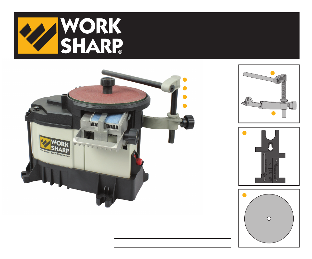
WS3000
Tool Bar Attachment
User’s Guide
Accepts Tormek® and JET®Jigs
and Accessories - Sold Seperately
See Tormek® or JET® instructions
for more information.
Parts Included:
A
• Tool Bar
B
• Bracket Assembly
C
• Set-Up Fixture
D
• P80 Abrasive
Videos at WorkSharpTools.com
A
B
C
TOOL STICKOUT
B
1
A
2
TOOL STICKOUT
3
D
Page 2
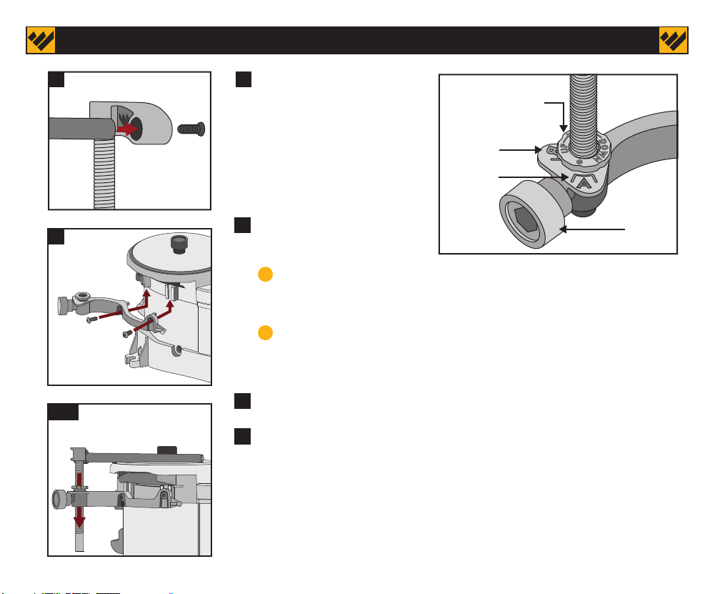
(1) Set Up Instructions:
1
2
3,4
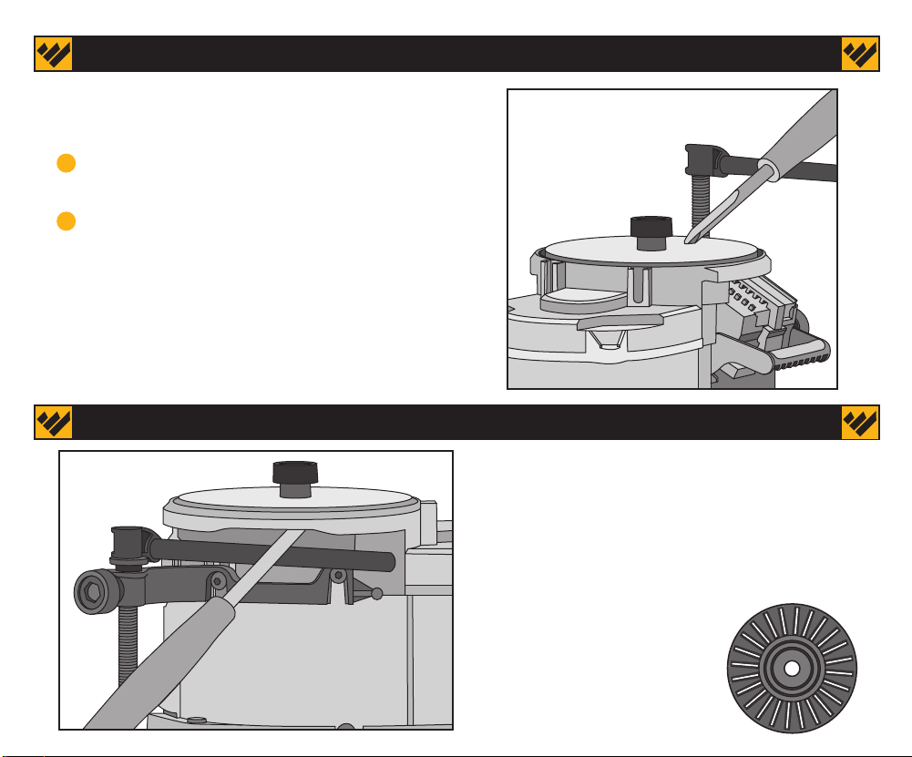
1 Insert tapped end of bar
into the tool bar knuckle
and use a mallet to tap bar
Micro-Adjust knob
with index mark
until it seats. Use provided
fastener (5/32” hex key) to
secure bar and create a
Position B
Position A
90° Tool Bar.
2 Secure Bracket onto
the Work Sharp 3000:
Tool Bar
Securing knob
A Insert the bracket fasteners (1/4” 20 Nuts) into
provided T-Slots of the back of the WS3000 as shown.
B Slide bracket up and into the T-Slots from the bottom
until bracket stops. Tighten the two fasteners to hold
bracket in place with a 5/32” hex key.
3 Insert Tool Bar into bracket as shown.
4 Square the Tool Bar to the wheel. Move the micro adjust
nut to the top of the rod and place the Tool Bar onto the
wheel and tighten the Tool Bar knob. Loosen the two bracket
fasteners and adjust the bracket until the bar is flat on the
wheel. Then re-tighten the bracket.
Jack screw on the bottom of the bracket can be used to micro adjust
the bracket position.
Page 3
(2) Abrasives
This kit contains a premium coarse P80 ceramic oxide abrasive from Norton. This should be used to shape
and sharpen tools. It is a very fast, yet cool, cutting abrasive and will shape or sharpen a tool very quickly.
Once your tools are shaped to your desired geometry, your standard Work Sharp 3000 abrasive kit (P120,
P400, P1000, 3600) will keep them sharp.
Abrasive Kit contains:
P120 Grit: Intended for roughing, shaping and sharpening.
P400 Grit: Intended for sharpening and edge refinement.
P1000 Grit: Intended for sharpening and edge refinement.
3600 Grit: Intended for honing and polishing.
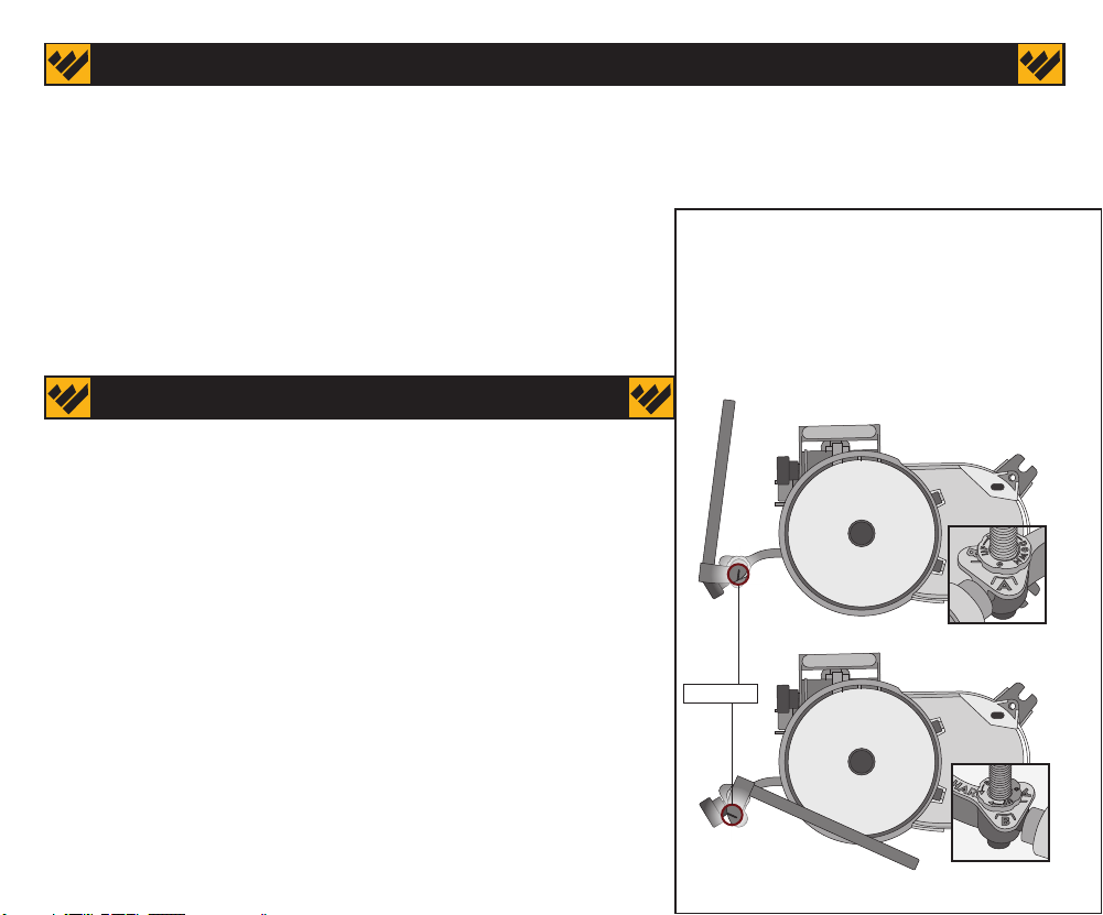
The Tool Bar has two primary positions
(A and B) but is infinitely adjustable to
meet your specific tool sharpening
needs.
Reference the Cast Line in the vertical
rod to set A or B position.
(3) Tips and Techniques
Heat Control:
Be aware of your tool’s temperature to avoid burning the steel.
Monitor the tool’s heat with your fingers. 150° is too hot to touch.
Steel is not affected until 400°. If a tool becomes too hot, allow it
to air cool or place it in a cup of water.
Changing the grinding point on the wheel can help control heat. The
wheel speed at the outer edge is faster (hotter) than the center of
the wheel (cooler).
Micro Adjust:
You can micro adjust your height setting to acheive nearly any
specific angle you desire (One full revolution is equivalent to .080
inches or +/- 2.5° at bevel angle).
This makes it faster and easier to match the existing angle already
sharpened onto your tool. This micro adjust nut will also hold the
height (H) setting for you if you need to loosen the tool bar securing
knob to swing the tool rest out of the way.
Cast Line
Position A
Position B
Page 4
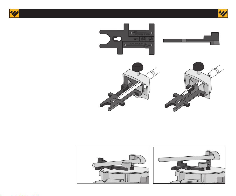
(4) Set Up Fixture
TSO B
TOOL STICKOUT
TSO A
TSO A
B
2
1
A
The Set Up Fixture helps set your
Tool Stick Out (TSO) and bar Height
(H). These two settings determine
the angle sharpened onto the tool.
Setting the Tool Stick Out (TSO)
There are two TSO settings (A and B).
Reference the specific tool sharpening
chart in this guide to determine which jig
is needed, and which angle you desire.
The chart will determine the TSO setting
you will need to use.
Setting the Tool Bar Height (H)
There are three height (H) settings for sharpening your tools. When
referencing the sharpening charts in this guide (Page 10, 15), the bar
height is not limited to those heights and can be adjusted to any
height needed. To create a standard, repeatable angle, reference the
tool sharpening charts
Tip: Tool Bar Height can also be
H1 H3
set by placing the tool into the
appropriate jig and adjusting
the tool bar height until the
tool bevel lays flat on the
abrasive wheel.
TOOL STICKOUT
3
TSO B
H1
H2
H3
Page 5
(5) Freehand Topside
The tool bar can be placed at various positions and
heights for topside freehand sharpening.
A Set the tool bar to desired height and orientation
to the grinding wheel.
B Set the tool stick out on tool rest so the bevel
angle matches that of your tool.
When holding the tool, your hand (fingers) can be used
to create a tool stop against the tool bar while
sharpening.
Tip: You can also scribe or mark a line onto your tool to
identify the Tool Stick Out and record the Height setting
for repeatable future sharpenings.
(6) Freehand Underside
The Tool Bar can be placed under the grinding
wheel on the back side of the machine. This
provides a stable tool rest for improved
precision.
When sharpening curved tools, use the
Edge-Vision® slotted wheel see through wheel and
abrasives.
Edge-Vision® Slotted Wheel
Page 6

(7) Data Chart
Use this data chart to record your sharpening set ups on various tools to
increase repeatability and reduce your set up time.
Tool Name
Tip: Use a Black Marker when re-sharpening an existing angle onto a tool. Color the bevel to be
sharpened then set up the tool (with or without jig) and Tool Bar so the bevel lays flat on the
abrasive wheel. Turn the wheel by hand one half revolution. If black marker is removed at the
heel of the bevel, use Micro-Adjust Knob to raise the Tool Bar. If black marker is evenly removed,
your set up is perfect. If marker is removed only at the cutting edge, use Micro-Adjust Nut to
lower the Tool Bar. Repeat until desired grind pattern and Tool Bar Height is achieved.
TSO
Tool Stick Out
H
Height
TBP: (A or B)
Tool Bar Position
Notes
Page 7

(8) Tool Rest Jig Tormek® SVD-100
Tip: Reference Tormek® instructions for more detail on jig set up and use.
Sharpening Scrapers:
• Mount tool bar in either ‘A’ or ‘B’ position.
A
Position A - best for angles less than 70°
Position B - best for angles between 70° and 90°
• Mount and clamp the Tool Rest onto the Tool Bar.
B
• Set the bar height (H) so tool rest is ¼” above the wheel.
C
• Place your scraper firmly onto the tool rest so the tip is
D
on the abrasive disk.
E
• Adjust the Tool Rest angle so the scraper bevel is flat on
the abrasive.
• Tighten the Tool Rest Knob to secure the chosen angle.
F
Or set the angle desired for your scraper by using a
protractor to measure the angle between the
abrasive and Tool Rest.
• Use the coarse P80 grit abrasive for the fastest results
G
and best burr formation.
• Smoothly work the tool back and forth on the abrasive
H
disk until a burr is raised.
Option: Use a burnishing rod to increase the burr at the
cutting edge.
Tip: Move the tool from one side to the other on the
tool rest in a smooth, steady motion. This will create
a consistent cutting edge. Avoid starting the
grinding in the center of the tool. Start at one side
and smoothly move the tool to the other side. Check
edge for grind pattern and sharpness progress
after every other pass.
CAUTION - Due to the rotation of the wheel, the tool
may want to push into or away from the tool rest.
Use a firm grip.
Page 8

(9) Short Tool Rest Jig Tormek® SVS-32
Tip: Reference Tormek® instructions for more detail on jig set up and use.
This jig is best used for quick and precise
sharpenings of short lathe turning tools and curved
or vee shaped carving tools.
A
Place the tool to be sharpened into the jig and
clamp tight.
B
Set the tool bar to your desired orientation to the
grinding wheel.
C
Adjust the tool bar Height using the Micro-Adjust
knob so the bevel angle on the tool lays flat on the
grinding wheel. Tighten the Tool Bar knob.
Saddle the jig onto the Tool Bar.
D
Start on one side and roll the tool and jig back and
E
forth to sharpen or hone.
Option: Scribe or mark a line onto your tool to identify
the Tool Stick Out and record the Height setting for
repeatable future sharpenings.
Tip: Move the tool from one side to the other on the tool
rest in a smooth, steady motion. This will create a
consistent cutting edge. Avoid starting the grinding in
the center of the tool. Start at one side and smoothly
move the tool to the other side. Check edge for grind
pattern and sharpness progress after every other pass.
Page 9

(10) Multi Jig Tormek® SVS-50 Set Up
Tip: Reference Tormek® instructions for more detail on jig set up and use.
Tool Set Up
1
Place Tool Bar in Position ‘B’.
2
Nest the ‘Vee Plate’ fixture or ‘Skew Tool’
fixture into the SVS-50 sharpening jig
• Use Vee Plate fixture for Roughing Gouges and
Parting Tools.
• Use Skew Tool fixture for Skew Chisels.
3
Clamp tool into the jig to the proper TSO setting.
Set your Tool Bar ‘H’ setting.
See Set Up Reference Chart specific to respective tool for
guidance. (on right)
4
Using the coarse P80 grit abrasive, sharpen the
entire bevel in one smooth pass.
Optional: Progress through the abrasive grits to refine the surface
finish of your tool. Use the same settings and technique for all
abrasives.
Set Up Reference Charts
Roughing Gouge
Grind
Angle
30°
38°
47°
Parting Tool
Grind
Angle
30°
38°
47°
Skew Chisel
Grind
Angle
31°
39°
48°
58°
TSO
Setting
B
B
B
TSO
Setting
B
B
B
TSO
Setting
B
B
B
B
Height
Setting
1
2
3
Height
Setting
1
2
3
Height
Setting
0
1
2
3
Tool Rest
Postition
B
B
B
Tool Rest
Postition
B
B
B
Tool Rest
Postition
B
B
B
B
Skew Tool Fixture Vee Plate Fixture
Note: One turn (+/-) of the micro adjust
nut effects grind angles 2.5-3° or .080 in
of the Tool Bar Height (H)
Page 10

(11) Multi Jig Tormek® SVS-50 with Roughing Gouge
Roughing Gouge
Use Vee Plate fixture when sharpening
Roughing Gouges
See Roughing Gouge Set Up Chart
(Section 10) for preset grind angles.
Or set the TSO and H to match the existing angle.
Record on the Data Chart in section 7.
Technique:
Roll the tool from one side to the other on the Tool Bar in a
smooth, steady motion. This will create a consistent grind
pattern and provide the sharpest, most consistent cutting
edge.
Do not start grinding in the center of the tool. Begin at one
side and smoothly roll the tool to the other edge. Check
edge for grind pattern and sharpening progress after every
other pass.
Page 11

(12) Multi Jig Tormek® SVS-50 with Parting Tool
Parting Tool
Use Vee Plate fixture when sharpening
Parting Tools
See Parting Tools Set Up Chart
(Section 10) for preset grind angles.
Or set the TSO and H to match the existing angle.
Record on the Data Chart in section 7.
Technique:
Set the edge of the Parting Tool flush onto the grinding
wheel. Hold firm to avoid movement.
Lift tool every few seconds and allow metal to cool before
reapplying.
Once fully sharpened, flip the tool over and sharpen the
other edge.
Page 12

(13) Multi Jig Tormek® SVS-50 with Skew Chisel
Skew Chisel
Use Skew Tool fixture when sharpening
Skew Chisel
See Skew Chisel Set Up Chart (Section
10) for preset grind angles.
Or set the TSO and H to match the existing angle.
Record on the Data Chart in section 7.
Technique:
Sharpen each bevel equally for best results and a
centered cutting edge.
Maintain firm downward pressure on the tool to prevent
the tool from moving during sharpening.
Sharpening one bevel into the wheel and the other bevel
away from the wheel does not impact the sharpness or
performance of the tool. This method is safe and creates a
very sharp skew chisel.
Page 13

(14) Gouge Jig Tormek® SVS-185 Settings
Tip: Reference Tormek® instructions for more detail on jig set up and use.
JS 0
JS 6
This chart shows how
changing the JS angle of the
Gouge Jig will change the
grind profile. Setting JS 0
provides little sweep back of
the cutting edge. To create a
fingernail or Ellsworth type
grind, use JS 6.
The Tormek® SVS-185 Gouge Jig is used to sharpen
bowl gouges of various sizes and profiles. This jig
can be used in 6 different Jig Settings (JS) to create
a wide range of cutting edge profiles. See chart
below for JS reference.
This jig comes complete from Tormek® with
instructions, hex key for adjustments, and labels
so you can document your set up for specific
tools.
See Gouge Jig Tips on page 17
JS 0 JS 1 JS 2 JS 3
JS 4
JS 5 JS 6
Page 14

(15) Gouge Jig Tormek® SVS-185 Settings
Gouge Jig Settings:
Gouges come in all shapes, types and grind profiles. The chart below will help you create some of the
more common grinds, but you will need to make adjustments for your specific sharpening needs.
Any desired grind angle and shape can be acheived by adjusting the TSO, JS and H settings.
Record all settings when creating a custom grind profile for repeatable and consistent results.
Use chart in section 7.
Grind
Angle
32°
35°
39°
42°
Grind
Angle
41°
45°
48°
52°
Bowl Gouge JS 0
TSO
Setting
Height
Setting
A
A
A
A
Bowl Gouge JS 4
TSO
Setting
Height
Setting
A
A
A
A
0
1
2
3
0
1
2
3
Tool Rest
Postition
B
B
B
B
Tool Rest
Postition
A
A
A
A
JS
Setting
0
0
0
0
JS
Setting
4
4
4
4
Grind
Angle
37°
40°
44°
47°
Grind
Angle
45°
49°
53°
58°
Bowl Gouge JS 2
TSO
Setting
Height
Setting
A
A
A
A
Bowl Gouge JS 6
TSO
Setting
Height
Setting
A
A
A
A
0
1
2
3
0
1
2
3
Tool Rest
Postition
A
A
A
A
Tool Rest
Postition
A
A
A
A
JS
Setting
2
2
2
2
JS
Setting
6
6
6
6
Page 15

(16) Gouge Jig Tormek® SVS-185 Technique
Abrasive Selection:
Use the P80 grit for fast and cool grinding.
This will quickly establish a smooth surface
finish and a burr. A burr will form on your tool
even though you may not be grinding the tool
perpendicular to the abrasive like on a
vertical grinder.
If you choose, you can progress to finer grit
abrasives for a more refined surface finish.
Technique:
When sharpening a tool with swept back sides, do not
over grind the center of the tool. Spend most of the
grind time on the sides/wings of the tool to create the
proper shape. Over grinding the tip or center of the
tool will not create the proper ‘swept back side’
geometry. Move smoothly and swiftly from side to
side for best surface finish and result.
Page 16

(17) Gouge Jig Tormek® SVS-185 Tips
1 Sharpening with the jig in setting JS 0 requires
little travel of the jig while sharpening. As you
increase the JS setting, you will need to increase
the sweep travel of the jig and tool to sharpen
further up the wings or sides.
Use the full 180° sweep of the jig when using
setting JS 6.
2 Sharpening in Tool Bar Position ‘A’ will allow for
maximum range of jig travel. Some tools can be
sharpened in Position “B” but the range of jig
travel may be restricted.
3 Some tools and/or jig settings can create
interference with the machine when sharpening.
Adjust the Tool Bar Position from position ‘A’ or ‘B’
so that the tool and jig can travel the full range of
motion needed without interference. Make these
set up adjustments before you start sharpening.
WARNING: This product contains a
chemical known to the State of
California to cause cancer. Some dust
created by power sanding and grinding
as well as contents from the machine
may contain chemicals known to the
State of California to cause cancer, birth
defects or other reproductive harm.
See WS3000 User’s Guide
for complete safety warnings.
4 Note that the Tormek® jig SVS-185 has a
different range of motion side to side due to the
‘offset’ of the vertical post on the horizontal slide
rail. The right side of the jig allows for full travel,
while the left side of the jig allows for less travel
since the tool hits the jig’s slide rail base. If you
move the jig from the right stop point to the left
stop point, your cutting edge created will vary
(longer wing on right side). This is inherent to this
jig. Please make accommodations by stopping
short of the stop on the right side so you can
create an even cutting edge.
Read Tormek® instructions for more information.
Darex, LLC
PO Box 730
210 E Hersey St
Ashland, OR 97520 USA
(800) 597-6170
PP0002604 Rev 0
www.worksharptools.com
 Loading...