

Woodstream 5145G User Manual

Certification Exhibit
FCC ID: SNA-5145G
IC: 9458A-5145G
FCC Rule Part: 15.209
IC Radio Standards Specification: RSS-210
ACS Project Number: 12-0177
Manufacturer: Woodstream Corporation
Model: 5140G
Manual
5015 B.U. Bowman Drive Buford, GA 30518 USA Voice: 770-831-8048 Fax: 770-831-8598

®
Fence Free
Pet Containment System
Système d’enclos
sans clôture pour animaux
OPERATING INSTRUCTIONS
Model
ModelModel
#5140G
#5140G#5140G

Congratulations on your purchase. The Havahart® Fence Free Pet Containment System can help you safely
and effectively train your dog to stay within the boundaries you set. Havahart is committed to caring control
of pets and wildlife. Through effective use of Havahart training products, our goal is to help strengthen the
bond between dogs and their owners.
Requirements:
1. Use on dogs 6 months and older and weighing over 8lbs. Do not use to contain puppies. Consult your
veterinarian before using the system if your dog has health problems.
2. Adequate time to install your inground fence.
3. Train your dog in 15 minute sessions, 3 times a day. Training should last a minimum of 15 consecutive
days. Consistency is the key to success.
This initial investment in time and energy will result in long-term rewards: security and exercise for your
dog and peace of mind for you!
Before you begin, it’s very important that you take the time to thoroughly review the instruction manual
and field training cards. These materials have been specially prepared in consultation with professional dog
trainers to help guide you though the installation and training process.
How does the Fence Free System work?
The Fence Free System uses state-of-the-art intelligent electronics to help train your dog to stay within the
boundaries you set. Through training, your dog will learn to recognize the boundary visually (aided by
flags), through an audio tone and a corrective static stimulus transmitted through the collar.
When the dog reaches the edge of the boundary signal, you will hear a warning tone that will last as long as
the dog remains in the warning zone. If the dog moves away, the tone shuts off. If the dog continues toward
the boundary, the initial low-level static stimulus occurs. If the dog still continues toward the boundary the
preset full-level static correction will be administered. You can set this level of correction to individually suit
your dog’s temperament.
The first time your dog receives a correction, normal reactions may be yelping or jumping. These reactions
will decrease as he/she becomes accustomed to the collar. You should notice improvements in your dog’s
behavior during the first week of training.
FREQUENTLY ASKED QUESTIONS
Will the Fence Free System work for my dog?
It’s important to remember that every dog has a unique personality and responds differently to stimuli.
While there is no way to know how your dog will react to the introduction of the training collar, Havahart
products have proven effective for use with dogs of virtually every size and breed that is 6 months and older
and weigh more than 8lbs.
For the safety and security of you and your dog, initial training should take place in a confined area where
you have complete control over the situation.
Is the Havahart Fence Free System safe?
The Havahart Fence Free System is safe and humane. To protect your dog and yourself, please observe the
following safety precautions:
2
• Never leave the collar on your dog for more than 12 hours at one time.
• Check collar fit each time you place collar on your dog– the collar must be fitted properly to work
effectively (see “Fitting the Collar”).
• Check dogs daily for skin irritation and do not use the collar if the skin is irritated.
• Always use the lowest stimulation possible to train your dog.
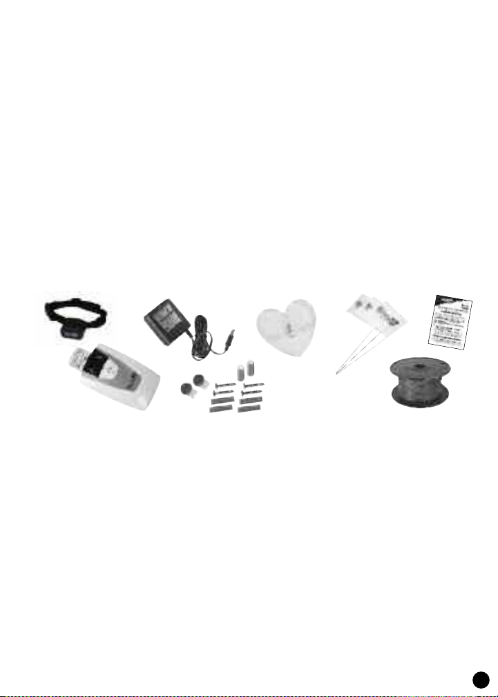
Contents of Havahart Fence Free System
1. Water Resistant SMART Collar Receiver with black nylon collar. Powered by a disposable CR2450 coin
lithium battery.
2. Wall-Mounted SMART Transmitter/ Control Box.
3. AC Adapter
4. (4) Wire Splicers
(2) short probes for short-haired dogs
(2) long probes for longer or thicker coated dogs.
(2) Screws & Anchors
5. Heart-shaped Tester
6. (50) Training Flags
7. 500 ft of Boundary Wire, 20 gauge
8. Field Training Cards
1.
3.
5.
6.
8.
2.
4.
Features of Havahart Fence Free System
The following built-in features help increase the system’s effectiveness:
• Run-Through Protection
When your dog runs towards the boundary, first a warning tone is emitted; if your dog continues towards
the fence, the collar will emit another warning tone accompanied by a low level warning static stimulus; if
your dog continues towards the boundary, he/she will receive the full level static stimulus that you have set.
The factory default setting is the lowest level of static correction.
• Over Correction Protection
If your dog becomes “trapped” or “confused” in the signal field, this feature limits stimulation. It does this
by stopping the static stimulus after 10 seconds and not accepting any additional signal from the fence for 30
seconds; therefore correction of your pet is stopped. The collar will automatically revert to normal operation
after this 30-second window.
• The Collar offers one level of tone only and 5 levels of tone with static stimulus. The collar comes ready to
use, preset at Level 2, the lowest level of tone and static stimulus.
• LED Loop Indicator Light to signal that the fence loop is complete.
• UL Listed Components Included.
7.
3
GETTING STARTED
To begin using your Havahart Fence Free System, you’ll need to plan and install the system boundary wire,
and make sure that the collar and the fence communicate with one another. While the system has been
designed for easy installation, please allow adequate time to complete each essential step as detailed in the
following instructions.
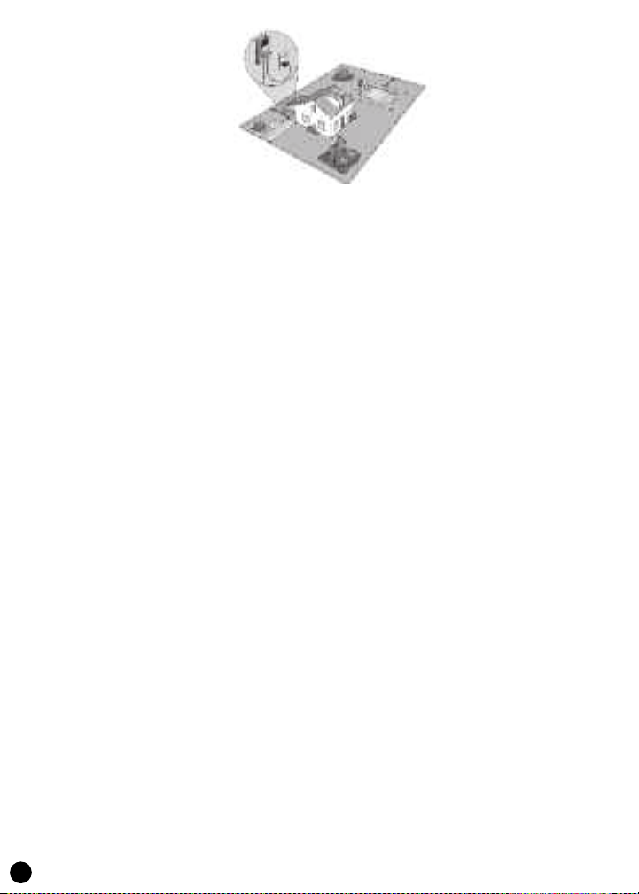
1. DESIGN YOUR BOUNDARY
• Contact your utility company to mark off utility lines (phone, electric, cable) before you install your
boundary wire. Using graph paper, select the areas of your property in which you want to contain your dog.
Make a diagram to help avoid obstacles or permanent objects in your yard, and consider the following:
• The boundary wire must make a continuous loop starting and stopping at the transmitter.
• Avoid sharp corners when laying your boundary wire. Rounded corners will produce a more consistent
signal field and avoid confusing your dog in these areas.
• Ideally the signal field width should be 6 to 8 feet, in other words, a 3 to 4 foot transmission area on either
side of the boundary wire. Plus, your dog will stay back another 2 to 4 feet from the edge of the signal field.
Consider these distances to avoid making passageways too narrow or your dog may be hesitant to use them.
• Stay 10 feet away from any neighbor’s underground fence to avoid signal interference.
2. INSTALLING THE WALL UNIT
Mount the wall unit on any interior wall near a standard household outlet with the enclosed screws. Make
sure the location is not subject to extreme summer heat or direct heating from the sun. Excessive heat will
interfere with the intelligent electronics.
Plug the power adapter into the wall outlet and plug the other end into the transmitter. Press the On/Off
button and the On/Off LED will light. The transmitter will withstand freezing temperatures, but it is not
waterproof and should be installed indoors, i.e. a garage, basement or shed.
Wall Unit Features
• Lightning/Surge Protection – The wall unit includes a built-in surge protector to protect it against normal
voltage spikes. However, your buried wire is a natural “lightning rod.” Because lightning strikes are massive
energy bursts and can damage the unit, it is recommended that you unplug the wall unit and disconnect the
wires during storms.
• Wire Connectors – Easy-to-use push release terminals on the back of the control unit let you quickly
connect or disconnect the boundary wire.
• Field Width Button – Controls the signal field width, this is the distance from the boundary wire to where
the collar is first activated.
4

• LED Indicator Light –The loop light appears when the fence loop is complete. The LED window displays
the field width in a numerical readout 1 through 5. If the fence loop is broken, the loop light will blink. Also,
an “L” indicates a broken loop wire. If there are no lights, check the connections, wires and power source for
problems such as: the wires are not properly connected; both wires are connected but the wire is broken or
nicked; power loss; or the transmitter has malfunctioned. If the problem persists, contact Woodstream
Consumer Care at 1-800-800-1819, option 1.
3. COLLAR OPERATION
Installing the Battery
Before you begin, install the lithium battery (included) in the collar. Install by removing the probes and the
collar strap. Use a coin to turn and open the battery hatch cover. Install the battery with the plus (+) side
facing up and replace the battery hatch cover.
The battery life will depend on how frequently your dog receives the static correction. If your dog is
sleeping or inactive, the collar will go into sleep mode (power saving mode) until the tilt vibration sensor
(collar movement) wakes it up. This smart collar function dramatically enhances battery life. The collar will
wake up instantly when it detects any motion.
You’ll know the collar batteries need to be replaced when you see the collar indicator light blink red every
10 seconds. If battery life is good the light will blink green every 10 seconds providing the collar has not
gone into sleep mode due to lack of motion.
Installing the Probes
Your collar comes from the factory installed with long probes for thick or long-haired breeds. You can use
the short probes for short-haired dogs. To change the probes, simply unscrew the probes. Be sure the rubber
insulator is between the probes and the collar strap. These insulators provide protection during damp
conditions and aid in the water resistance. Hand-tighten the probes as far as you can.
Fitting the Collar
Very Important! The collar must be fitted properly to work effectively.
Be sure the collar is turned Off. Position the collar high up on your pet’s neck underneath the chin, with the
probes facing upward touching the pet’s skin. Make sure probes maintain contact with skin. Adjust nylon
collar to fit snug but not tight. You should be able to slide one finger between your pet’s coat and the training
collar. The correct fit is essential because most training failures are caused by probes not making direct contact
with the skin.
Once collar is adjusted to correct length, remove collar, trim excess, and use a match to carefully melt the
end of the strap to prevent fraying. Remember, for growing dogs, check collar size weekly and adjust when
necessary. Allow enough nylon for the collar to grow with your dog.
IMPORTANT: Never leave collar on the dog for more than 12 consecutive hours.
Turning Collar On & Off:
To turn collar on, push the collar On/Off button and hold it for 2 seconds. This button is located on the back
of the collar next to the probes. A green LED light will appear, and the collar will buzz. Release the button
– your collar is now ready to go.
5

Immediately after the collar turns on the light will blink. The number of blinks will correspond to the static
stimulus setting level. One blink means it is set at Level 1 - Tone Only, two blinks means Level 2 , three
blinks means Level 3, etc.
To turn the collar off, push the collar On/Off button and hold it for 2 seconds. A red LED light will appear,
and the collar will buzz. Release the button and the collar will be turned off.
4. INSTALLING THE BOUNDARY WIRE
Tools Needed For Installation
• Straight-edged spade
• Caulk gun with silicone caulking
• Safety Glasses
• Circular saw with masonry blade - for cutting concrete or driveway
• Flathead screwdriver
• Electrical tape
• Drill with drill bit or masonry bit
Boundary wire should be laid above the ground according to your design from Step 1.
DO NOT BURY WIRE UNTIL YOU HAVE TESTED THE SYSTEM AND ARE SURE IT IS
WORKING PROPERLY.
For the system to work properly, the wire must make one continuous loop. The signal is transmitted from
one terminal of the wall mount transmitter, through the wire, and back to the other terminal.
Knowing where any utility obstacles might be (phone, electric, cable) lay out the wire above ground. Stay at
least 6 feet away from any utility obstacle that runs parallel with your designated boundary. We recommend
a 6-8 foot total signal field to ensure the best operation of the warning tone and the run through protection
feature.
Signal field width can vary with conditions (snow, fall foliage), wire length, wire gauge, etc. (see “Setting the
Signal Field for Boundary Width”). Use round corner turns to follow the perimeter of your fence
installation. Avoid making passageways too narrow or your dog may hesitate to use them.
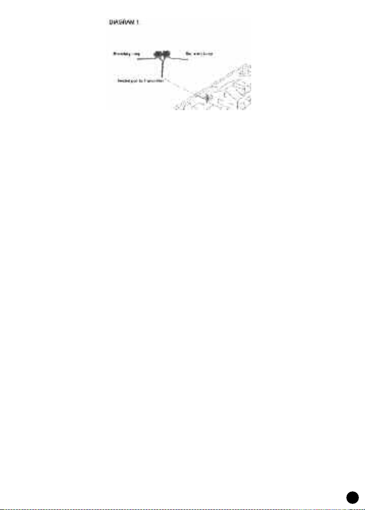
Cancelling the Signal
You must cancel the signal in the areas where you don’t want your dog to receive a correction, such as
inside the garage or the driveway area close to the house. Twisting two strands of live wire cancels the
signal. To twist the wire, cut two equal lengths and hold them side-by-side. Insert both ends of wire in a
power drill; spin both ends until the twists are 1-3 inches apart. The tighter the wire, the better the signal
cancellation. The wires can also be twisted manually. Both ends of the twisted section need to be spliced
back into the main loop. Remember it is only live, powered wires that cancel one another when twisted.
(See boundary diagram on page 4).
Connecting the Loop to Wall Unit
• Splice the two ends of the twisted wire to each of the two ends of loop wire. (See Diagram 1)
6
• Drill a hole through exterior wall or window/door or run wire through an existing utility line hole.
• Connect the twisted wire to the wall unit terminals. Wire ends must be stripped before connecting. Make sure
the twisted wire runs up to the wall unit before separating the wires for placement into the terminals. Failure to
do this can cause a miniature live circuit that can trigger stimulation of the collar right at the wall unit.
• Once unit is turned on and the On/Off light is on, the Loop LED should also be on, indicating a continuous loop.
Testing the Wire/ Collar Testing
Before burying the wire, test it by turning on the wall mount transmitter and setting the desired signal field
width. This is only for test purposes. There is more information on “Setting the Signal Field.” Hook up the
heart-shaped tester to the collar probes and slowly walk the collar toward the boundary wire. Listen for the
warning tone and watch the test light illuminate.
Burying the Wire
Once you’re sure the system is working, bury the wire. Using a flat blade spade or edging tool, cut
approximately 1/2” into ground. Begin near the wall mount transmitter and continue around the path of
loop wire. Push wire into ground using fingers or a blunt tool, such as a paint stick. Cover the wire with dirt
or turf.
When crossing an asphalt driveway, make a 1/2” deep cut using a circular saw and masonry blade. Place the
wire in the crack and seal with asphalt sealant. If possible, use expansion joints on driveways and sidewalks;
place the wire in the joint and seal with an outdoor caulk. When crossing gravel or installing in water, bury
the wire using old garden hose or plastic PVC pipe to protect the wire and securely anchor pipe or hose.
Setting the Signal Field Width
Once the power and loop lights are on, you can set the signal field width. This is the area on each side of the
wire that activates the warning tone and static stimulus level on the collar. There are 5 field intensity
settings; the factory setting is 6 feet (3 feet on either side of the wire). You may wish to adjust this field
width based on your yard size. At the top of the transmitter is a pop-up menu that shows the different
settings. The signal field is displayed in the LED window.
Note: Signal field width from your fence wire will vary from these published specifications due to gauge of
wire, length of wire installed, depth of wire and a variety of other possible factors. The wall unit is capable of
driving a fence signal through many spools of wire. In order to normalize this signal field width for all
installations and for multiple other variables, your Fence Free System includes a SMART controller. The
SMART controller automatically calibrates the output to the wire such that adequate power is delivered to
create the specified field widths as closely as possible.
7
 Loading...