


UDS-N1/N2 ULTRASNIC SCALER
INSTRUSTION MANUAL
Contents
1.The installation and components of equipment————————————1 1.1 Instruction——————————————————————————1 1.2 Components—————————————————————————1
1.3 The main technical specifications—————————————————1
1.4 Installing and connecting of the components—————————————2
2.Product function and usage————————————————————4 2.1 Working principle———————————————————————4 2.2 Scaling function————————————————————————5
3.Sterilization and maintenance———————————————————8 3.1 Sterilization of tips and wrench——————————————————8 3.2 Sterilization of tips and wrench (UDS-N1)————————————8
3.3 Cleaning of tips and wrench (UDS-N1)—————————————8
3.4 Sterilization of detachable handpiece(UDS-N2)———————————8
3.5 Sterilization of torque wrench (UDS-N2)——————————————9
3.6 Clean of tips and torque wrench (UDS-N2)—————————————9
3.7 Troubleshooting and notes———————————————————10
4.Notice————————————————————————————11 4.1 Notice when using equipment——————————————————11 4.2 Contraindication———————————————————————12 4.3 Storage and maintenance————————————————————12 4.4 Transportation————————————————————————13 4.5 Manufacturer’s rights—————————————————————13
5.After-service—————————————————————————13
6.Environmental Protection————————————————————13
7.For technical data, please contact—————————————————14
8.Manufacturer’s right——————————————————————14
9.Symbol instruction——————————————————————14
10.Declaration of conformity———————————————————15 10.1 Product conformity the following standards————————————15 10.2 EMC - Declaration of conformity————————————————15
11.Statement——————————————————————————18

1. The installation and components of equipment
1.1 Instruction
The “Woodpecker” built-in ultrasonic scaler UDS-N1 and UDS-N2 made in Guilin Woodpecker Medical Instrument Co., Ltd. are used along with dental unit for teeth cleaning. They are also indispensable equipments for tooth disease prevention and treatment.
1.2 Components
1.2.1The components of the machine are listed in the packing list.
1.2.2Product performance and structure
Ultrasonic scaler is composed of elect circuit, water way and ultrasonic transducer.
1.2.3 Scope of application
Ultrasonic scaler UDS-N1 and UDS-N2 is used for the dental calculus elimination.
1.3 The main technical specifications
1.3.1 Technical specifications of ultrasonic scaler a) Power input:
With transformer 220 - 240V~ 50Hz/60Hz 150mA Without transformer 24V~ 50Hz/60Hz 1.3A
b)Output primary tip Vibration excursion: ≤100μm
c)Output half-excursion force: <2N
d)Output tip vibration frequency: UDS-N1: 30kHz±3kHz
UDS-N2: 28kHz±3kHz
e)Output power: 3W to 20W
f)Water pressure: 0.01MPa to 0.5MPa
g)Weight of main unit: 0.2kg
h)Main unit fuse: T1.6AL 250V
i)Weight of transformer: 1kg (optional)
j)Operating mode: Continuous operation
1
k)Type of protection against electric shock: Class II equipment
l)Degree of protection against electric shock: Type BF equipment
m)Degree of protection against harmful ingress of water: Ordinary equipment (IPX0)
n)Protection degree against water(used on the pedal): IPX1
o)Applied part of the equipment: handpiece and tip
p)Degree of safety of application in the presence of a flammable anesthetic mixture with air or with oxygen or nitrous oxide: Equipment can not be used in the presence of a flammable anesthetic mixture with air or with oxygen or nitrous oxide.
1.3.2 Working condition
a)Environment temperature: 5 to 40
b)Relative humidity: ≤80%
c)Atmosphere pressure:70kPa to 106kPa
1.4 Installing and connecting of the components
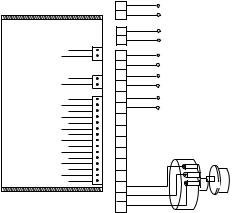
1.4.1 The installing and connecting illustration of the equipment’s components are showed as picture 1:
UDS-N1
19 17 15 13 11 9 7 5 3 1 18 16 14 12 10 8 6 4 2
1
2
3
4
5
6
7
8
9
10
11
12
13
14
15
16
17
18
19
picture 1 a)
2
Notice:
a)Please connect power supply and pneumatic switch (or foot pedal) as picture 1 a) showed.
b)Lead No.5 and lead No.6 should be connected with 24V~,and this circuit is disallowed to act as switch circuit.
c)Lead No.7 and lead No.8 should be connected with pneumatic switch (or foot
switch) directly, and this circuit acts as switch circuit and is disallowed to do the short circuit.
1 2
1 |
Socket for handpiece |
|
|
2 |
|
3 |
|
4 |
|
5 |
|
6 |
|
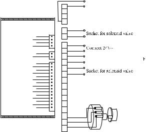
UDS-N2
Picture 1 b)
|
3 |
4 |
|
|
5 |
6 |
|
|
7 |
8 |
|
|
9 |
12 10 |
13 11 |
20 18 16 14 |
21 19 17 15 |
7 |
|
|
8 |
|
|
9 |
Pneumatic switch or foot switc |
|
10 |
||
|
||
11 |
|
|
12 |
|
|
13 |
|
|
14 |
|
|
15 |
|
|
16 |
|
|
17 |
|
|
18 |
Potentiometer |
|
19 |
||
20 |
|
|
21 |
|
Notice:
a)Please connect power supply and pneumatic switch (or foot pedal) as picture 1 b) showed.
b)Lead No.7 and lead No.8 should be connected with 24V~, and this circuit is disallowed to act as switch circuit.
c)Lead No.9 and lead No.10 should be connected with pneumatic switch (or foot switch) directly, and this circuit acts as switch circuit and is disallowed to do the short circuit.
3
1.4.2 The followings should be noticed during installation.
a)Pneumatic power switch, pneumatic penstock and pneumatic foot switch are equipped by manufacturers of the dental unit or the end-users.
b)The manufacturers of dental unit, the dealers or end-users of the equipment need to dig holes in salver of dental unit so as to fix potentiometer and fetch out the silica gel pipe of handpiece cable.
c)Be care the proper space for dispersing heat of ultrasonic generator.
d)Built-in ultrasonic scaler without transformer occupies a less space ,and works with current 24V~, power≥20W.
e)Turn the potentiometer knob to the minimum and the water control switch the maximum before turning on the scaler.
f)The frequency of ultrasonic scaler is extremely high. Under normal water supply, a light touch and a certain to-and-fro motion will eliminate the tartar without obvious heat. Overexertion and longtime lingering are forbidden.
2. Product function and usage
2.1 Working principle
2.1.1Summarization: the built-in ultrasonic scaler is consist of ultrasonic generator (circuit), cable, handpiece (transformer), scaling tip, pneumatic switch (the power switch of pneumatic penstock and the circuit’s commutating and filtering, is controlled by pneumatic foot pedal of dental unit and switch for handpiece rack of ultrasonic scaler at the same time) and switch for handpiece rack (it controls the air supply which gets through pneumatic penstock and pneumatic power switch. And the air supply is off when handpiece is in the rack and on when handpiece out).
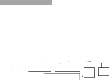
2.1.2Chart of working principle:
Water supply |
|
Pneumatic penstock |
|
Water adjustment |
|
Handpiece |
Air supply 
 Pneumatic foot switch
 Switch for handpiece rack
Power supply(connect to dental unit with 24V~)
Pneumatic Ultrasonic power  generator switch
4
The air supply is on when the handpiece is out from the rack. Step on the foot switch, pneumatic power switch, pneumatic penstock, ultrasonic generator, handpiece and scaling tip all start working at the same time, and water supply is open.
2.2 Scaling function
2.2.1 Instruction of wrench (UDS-N1)
a)Screw the tip on the handpiece.
b)Make the tip inside the wrench’ s hole.
c)Screw or unscrew the tip as picture 2 showed.
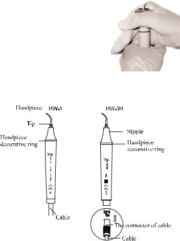
Picture 2 2.2.2 Instruction for main components of scaled and detachable handpiece (showed in picture 3)
Picture 3
a)Nipple: The nipple can be removed. You can termly screw off the nipple and clean the pole with alcohol.
b)Handpiece decorative ring: The seal can termly be removed and cleaned with alcohol.
5
 Loading...