

WoMaster WR312G-LTE-E, WR322GR Series, WR312G-LTE-AU, WR312G-LTE-U, WR312G-LTE-CN User Manual
...Page 1

C
COVER
WR302G/WR312G/WR322GR
Industrial Secure Cellular Router (Serial Server)
Aug.23.2018 V.1
WOM ASIA Co., Ltd
1F., No.185-3, Kewang Rd., Longtan Dist., Taoyuan 325, Taiwan
Page 2

2
WoMaster
WR302G/WR312G/WR312G C Series/WR322GR /WR322GR C Series
Industrial Secured and Rugged LTE Serial Router
User Manual
Copyright Notice
© WoMaster. All rights reserved.
About This Manual
This user manual is intended to guide a professional installer to install and to configure the WoMaster
Industrial Secured and Rugged LTE Serial Router. It includes procedures to assist you in avoiding
unforeseen problems.
NOTE:
Only qualified and trained personnel should be involved with installation, inspection, and repairs of this
router.
Disclaimer
WoMaster reserves the right to make changes to this Manual or to the product hardware at any time without notice.
Information provided here is intended to be accurate and reliable. However, it might not cover all details and
variations in the equipment and does not claim to provide for every possible contingency met in the process of
installation, operation, or maintenance. Should further information be required or should particular problem arise
which are not covered sufficiently for the user’s purposes, the matter should be referred to WoMaster. Users must be
aware that updates and amendments will be made from time to time to add new information and/or correct possible
unintentional technical or typographical mistakes. It is the user’s responsibility to determine whether there have
been any such updates or amendments of the Manual. WoMaster assumes no responsibility for its use by the third
parties.
WoMaster Online Technical Services
At WoMaster, you can use the online service forms to request the support. The submitted forms are stored in server
for WoMaster team member to assign tasks and monitor the status of your service. Please feel free to write
to [email protected]
if you encounter any problems.
Page 3

3
TABLE OF CONTENTS
COVER ....................................................................................................................................................................... 1
TABLE OF CONTENTS ................................................................................................................................................. 3
1. INTRODUCTION ................................................................................................................................................... 6
OVERVIEW ...................................................................................................................................................... 6
1.1
1.2
MAJOR FEATURES ........................................................................................................................................... 8
2. HARDWARE INSTALLATION.................................................................................................................................... 9
2.1 HARDWARE
DIMENSION ................................................................................................................................ 9
2.2 INSTALLATION .............................................................................................................................................. 11
2.3 WIRING
2.4 WIRING
2.5 CONNECTING
2.6
DIN RAIL MOUNTING .................................................................................................................................... 13
2.7
ANTENNA ..................................................................................................................................................... 14
2.8
SIM/SD CARD INSTALLATION ......................................................................................................................... 16
THE POWER INPUTS ........................................................................................................................ 11
THE ALARM REL AY OUTPUT (DO) .................................................................................................... 12
THE GROUNDING SCREW ........................................................................................................ 12
3. WEB MANAGEMENT CONFIGURATION ............................................................................................................... 17
SYSTEM ......................................................................................................................................................... 19
3.1
3.1.1 INFORMATION ...................................................................................................................................... 19
3.1.2 LOGIN SETTING ..................................................................................................................................... 20
3.1.3 NETWORK SETTING ............................................................................................................................... 24
3.1.4 DATE AND TIME .................................................................................................................................... 26
3.1.5 DHCP SERVER ........................................................................................................................................ 27
3.2
ETHERNET PORT ............................................................................................................................................ 29
3.2.1 ETHERNET STATUS ................................................................................................................................ 29
3.2.2 ETHERNET SETTING ............................................................................................................................... 30
3.2.3 TRAFFIC CONTROL ................................................................................................................................. 31
3.3
REDUNDANCY ............................................................................................................................................... 32
3.3.1 RSTP STATUS ......................................................................................................................................... 32
3.3.2 RSTP BRIGDE SETTING ........................................................................................................................... 33
3.4
SERIAL .......................................................................................................................................................... 35
3.5
CELLULAR ...................................................................................................................................................... 39
3.5.1 CELLULAR STATUS ................................................................................................................................. 39
3.5.2 CELLULAR SETTING ................................................................................................................................ 41
3.5.3 SIM SETTING ......................................................................................................................................... 44
3.6
GPS ............................................................................................................................................................... 46
Page 4

4
3.6.1 GPS STATUS .......................................................................................................................................... 46
3.6.2 GPS SETTING ......................................................................................................................................... 47
3.7
WIRELESS LAN ............................................................................................................................................... 48
3.7.1 WLAN STATUS ....................................................................................................................................... 48
3.7.2 WLAN SETTING ...................................................................................................................................... 48
3.7.3 WLAN SECURITY .................................................................................................................................... 62
3.7.4 ADVANCED ............................................................................................................................................ 64
3.7.5 ACCESS CONTROL (AP MODE) ............................................................................................................... 66
3.7.6 RADIUS SERVER (AP MODE) .................................................................................................................. 68
3.7.7 CERTIFICATE FILE (CLIENT MODE) .......................................................................................................... 69
3.7.8 AUTO OFFLOAD (CLIENT MODE) ............................................................................................................ 69
3.8
SECURITY ...................................................................................................................................................... 71
3.8.1 ACCESS CONTROL .................................................................................................................................. 71
3.8.2 OUTBOUND FIREWALL .......................................................................................................................... 75
3.8.3 NAT SETTING ......................................................................................................................................... 79
3.8.4 OPEN VPN ............................................................................................................................................. 82
3.8.5 IPSEC SETTING ....................................................................................................................................... 88
3.8.6 GRE SETTING ......................................................................................................................................... 90
3.9
ROUTING ...................................................................................................................................................... 91
3.9.1 STATIC ROUTE ....................................................................................................................................... 91
3.9.2 RIPv2 ..................................................................................................................................................... 92
3.10
WARNING ................................................................................................................................................... 92
3.10.1 EMAIL ALERT ....................................................................................................................................... 92
3.10.2 PING WATCHDOG................................................................................................................................ 93
3.10.3 SYSLOG SETTING ................................................................................................................................. 94
3.10.4 RELAY OUTPUT .................................................................................................................................... 95
3.10.5 EVENT TYPE ......................................................................................................................................... 95
3.10.6 SNMP .................................................................................................................................................. 96
3.11
DIAGNOSTICS ............................................................................................................................................ 100
3.11.1 EVENT LOGS ...................................................................................................................................... 100
3.11.2 ARP TABLE ......................................................................................................................................... 101
3.11.3 PING .................................................................................................................................................. 102
3.11.4 TRACEROUTE ..................................................................................................................................... 102
3.11.5 NETWORK STATISTICS ....................................................................................................................... 103
3.11.6 CLIENT ASSOCIATION LIST ................................................................................................................. 104
3.12
IOT ............................................................................................................................................................ 105
3.12.1 AWS IoT ............................................................................................................................................ 105
3.12.2 AZURE IoT ......................................................................................................................................... 108
3.12.3 WoM IoT ........................................................................................................................................... 111
3.12.4 MODBUS LOGGING ........................................................................................................................... 115
Page 5

5
3.13 BACKUP AND RESTORE .............................................................................................................................. 116
3.14
FIRMWAR E UPGRADE ............................................................................................................................... 117
3.15
RESET TO DEFA U LT S ................................................................................................................................... 118
3.16
SAVE ......................................................................................................................................................... 118
3.17
LOGOUT .................................................................................................................................................... 119
3.18
REBOOT .................................................................................................................................................... 119
3.19
WOMASTER MIB ....................................................................................................................................... 120
4. REVISION HISTORY ............................................................................................................................................ 121
Page 6
6
1. INTRODUCTION
1.1 OVERVIEW
WR302G/312G/322GR Series is an innovative Industrial Secure LTE router. WR312G Series is designed for IIOT
applications by single radio LTE/Wi-Fi of WR312G or dual radio LTE + Wi-Fi of WR322GR. LTE 2T2R MIMO delivers
high bandwidth up to 150Mbps uplink and 50Mbps downlink, while IEEE 802.11ac Wi-Fi 2T2R MIMO delivers high
bandwidth up to 866Mbps. Two RS232/422/485 ports are able to connect to local serial devices. The support of
OpenVPN and IPsec provides security to the gateway. For the best traffic control, the device management side
features have been utilized: NAT Routing and Traffic shaping.
The WR302G/312G/322GR Series provides 2-port Gigabit Ethernet for routing or bridging that can boost high
throughput network performance. The USB design helps easy field installation; it is not supported in C Series model.
The SD card can store application programs or diagnostic log file.
This Industrial Secure LTE router also can be smartly configured by WoMaster advanced management utility, Web
Browser, SNMP, Telnet and Command Line Interface.
Excellent security features also provided, such as Firewall, Demilitarized Zone (DMZ), Port Forwarding, HTTPs, SSH for
Telnet security, and many other security features. All of these features in order to ensure the secure data
communication.
WoMaster’ Industrial Secure LTE router is designed to provide fast, secure, and more stable network. One advantage
that makes it a powerful wireless router is that it equips with wireless redundancy technologies such as cellular to
ETH WAN redundancy and wireless/cellular auto offload. Besides, IEC 61000-6-2 / 61000-6-4 Heavy Industrial and
wayside EN50121-4 EMC certified design, rugged enclosure and -40~75°C wide operating temperature range, all of
these features guarantee stable performance of WR302G/312G/322GR Series for wireless surveillance data
transmission for Wayside and ITS Application.
Model Name Description
WR302G Industrial Secure Serial Server, 2GbE+2COM
WR312G-LTE-E
WR312G-LTE-AU
WR312G-LTE-U
Industrial Secure Cellular Router, 2GbE+2COM, LTE-E, FDD B1/3/5/7/8/20, TDD
B38/40/41
Industrial Secure Cellular Router, 2GbE+2COM, LTE-AU, FDD B1/2/3/4/5/7/8/28, TDD
B40
Industrial Secure Cellular Router, 2GbE+2COM, LTE-U, FDD B2/4/12,
B2/B4/B5@WCDMA
WR312G-LTE-CN
Industrial Secure Cellular Router, 2GbE+2COM, LTE-CN, FDD B1/B3/B5/B8, TDD
B38/B39/B40/B41
Industrial Secure Cellular Router, 2GbE+2COM, 802.11ac/n WLAN, LTE-E, RSIM, GPS,
WR322GR-WLAN+LTE-E
FDD B1/3/5/7/8/20, TDD B38/40/41
Page 7

7
WR322GR-WLAN+LTE-U
Industrial Secure Cellular Router, 2GbE+2COM, 802.11ac/n WLAN, LTE-U, RSIM, GPS,
FDD B2/4/12, B2/B4/B5@WCDMA
WR322GR-WLAN+LTE-CN
WR322GR-WLAN+LTE-E
WR322GR-WLAN+LTE-AU
WR322GR-WLAN+-LTE-U
WR322GR-WLAN+LTE-CN
WR312G-LTE-E (C Series) Industrial Secure Cellular Router, 2GbE+1COM, LTE-E, 2SIM, FDD B1/3/5/7/8/20, TDD
WR312G-LTE-AU (C Series) Industrial Secure Cellular Router, 2GbE+1COM, LTE-AU, 2SIM, FDD B1/2/3/4/5/7/8/28,
Industrial Secure Cellular Router, 2GbE+2COM, 802.11ac/n WLAN, LTE-CN, RSIM, GPS,
FDD B1/B3/B8, TDD B38/B39/B40/B41
Industrial Secure Cellular Router, 2GbE+2COM, 802.11ac/n WLAN, LTE-E, RSIM, GPS,
FDD B1/3/5/7/8/20, TDD B38/40/41
Industrial Secure Cellular Router, 2GbE+2COM, 802.11ac/n WLAN, LTE-AU, RSIM, GPS,
FDD B1/2/3/4/5/7/8/28, TDD B40
Industrial Secure Cellular Router, 2GbE+2COM, 802.11ac/n WLAN, LTE-U, RSIM, GPS,
FDD B2/4/12, B2/B4/B5@WCDMA
Industrial Secure Cellular Router, 2GbE+2COM, 802.11ac/n WLAN, LTE-CN, RSIM, GPS,
FDD B1/B3/B5/B8, TDD B38/B39/B40/B41
B38/40/41
TDD B40
WR312G-LTE-U (C Series) Industrial Secure Cellular Router, 2GbE+1COM, LTE-U, 2SIM, FDD B2/4/12,
B2/B4/B5@WCDMA
WR312G-LTE-CN (C Series) Industrial Secure Cellular Router, 2GbE+1COM, LTE-CN, 2SIM, FDD B1/B3/B5/B8, TDD
B38/B39/B40/B41
WR322GR-WLAN+LTE-E (C
Series)
WR322GR-WLAN+LTE-AU (C
Series)
WR322GR-WLAN+-LTE-U (C
Series)
WR322GR-WLAN+LTE-CN (C
Series)
*GPS model by request
Industrial Secure Cellular Router, 2GbE+1COM, 802.11ac/n WLAN, LTE-E, 2SIM, FDD
B1/3/5/7/8/20, TDD B38/40/41
Industrial Secure Cellular Router, 2GbE+1COM, 802.11ac/n WLAN, LTE-AU, 2SIM, FDD
B1/2/3/4/5/7/8/28, TDD B40
Industrial Secure Cellular Router, 2GbE+1COM, 802.11ac/n WLAN, LTE-U, 2SIM, FDD
B2/4/12, B2/B4/B5@WCDMA
Industrial Secure Cellular Router, 2GbE+1COM, 802.11ac/n WLAN, LTE-CN, 2SIM, FDD
B1/B3/B5/B8, TDD B38/B39/B40/B41
Page 8

8
1.2 MAJOR FEATURES
Below are the major features of WR302G/312G/322GR Series:
- 2 x 100/1000MBase-T RJ45, Auto Negotiation for routing or briding
- LTE 2T2R MIMO delivers high bandwidth up to 150Mbps uplink and 50Mbps downlink
- IEEE 802.11ac Wi-Fi 2T2R MIMO delivers high bandwidth up to 866Mbps
- Advanced management features: IPv4, SNMP v1/v2c/v3/Trap, MIBs, DHCP server/client, TFTP, System Log, SD
card configuration.
- Cellular Configuration: Radio on/off, 4G LTE/3G HSPA Configuration, SIM Security, Connection Status,
- Wireless redundancy: Cellular to Eth-WAN Redundant,wireless auto offload
- Advanced Security system by OpenVPN, IPsec, Firewall, DMZ, Port Forwarding, HTTPs Login and SSH Telnet
- Event Notifications through E-mail, SNMP trap and SysLog
- Traffic Management features: NAT Routing and Traffic shaping.
- CLI interface, Web, SNMP for network Management
- Multiple event relay output for enhanced alarm control
- EN50121-4 for Industrial IoT, ITS, Railway track side application.
- Steel Metal with Aluminum for heat dissipation
- Wide range operating temperature -40~75˚C
- IP30 ingress protection
Page 9
9
2. HARDWARE INSTALLATION
This chapter introduces hardware and contains information on installation and configuration procedures.
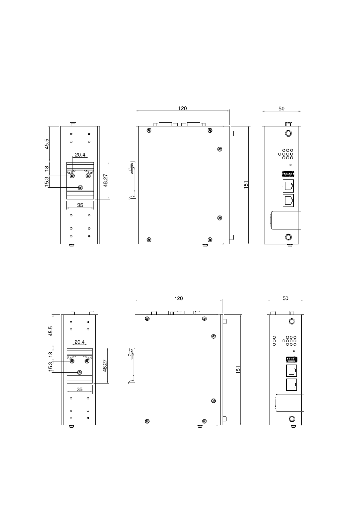
2.1 HARDWARE DIMENSION
Dimensions of WR312G: 50 x 151 x 120 (W x H x D) / without DIN Rail Clip
Dimensions of WR322GR: 50 x 151 x 120 (W x H x D) without DIN Rail Clip
Page 10
10
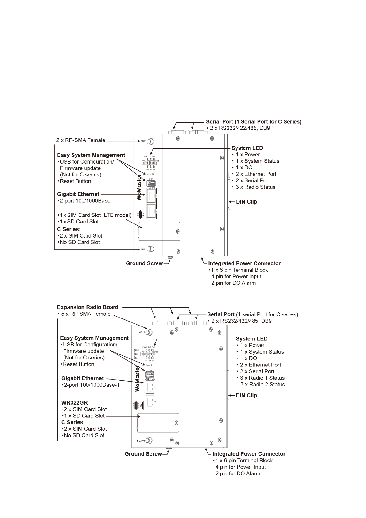
Front Panel Layout
The front panel from WR312G and WR322GR routers include 2 ports Giga Ethernet (100/1000 Base-T, RJ45), 2 Serial
Ports (RS232/422/485), System LED, USB for configuration/firmware management (Not available for C Series), 1 x 6-pin
terminal block connector (4 pin for power inputs and 2 pin for DO alarm) and 1 chassis grounding screw. The
difference for WR312G is provided with 2 antenna sockets while WR322GR is provided with 5 antenna sockets. On
the rear side of the device, there is DIN rail clip attached.
WR312G
WR322GR
Page 11
11
2.2 INSTALLATION
After unpack the box, follow the steps below in order to properly connect the device. For better Wi-Fi performance,
put the device in a clearly visible spot, as obstacles such as walls and doors hinder the signal.
1. First, assemble router by attaching the necessary antennas and inserting the SIM card.
2. To power up router, please use the power adapter included in the box.
WARNING: Using a different power adapter can damage and void the warranty for this product
2.3 WIRING THE POWER INPUTS
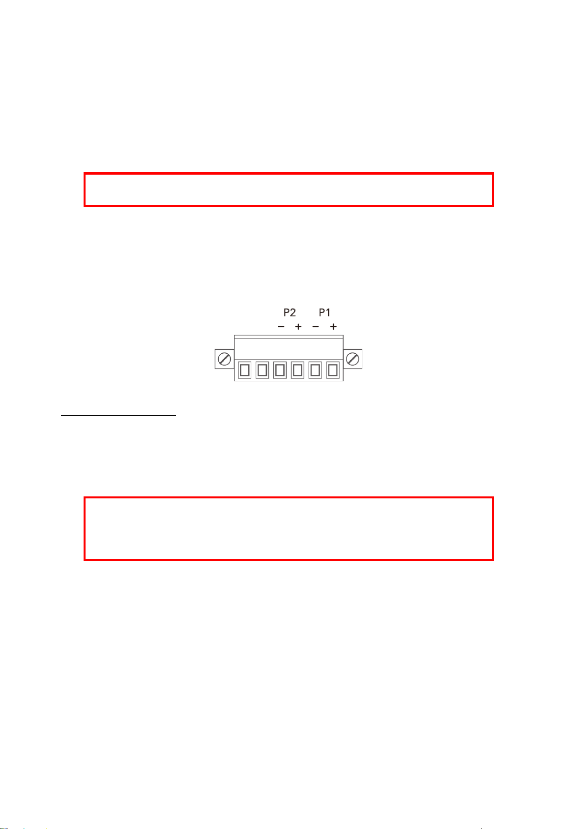
Power Input port in the router provides 2 sets of power input connections (P1 and P2) on the terminal block. On the
picture below is the power connector.
Wiring the Power Input
1. Insert the positive and negative wires into the V+ and V- contact on the terminal block connector.
2. Tighten the wire-clamp screws to prevent the power wires from being loosened.
3. Connect the power wires to suitable DC Switching type power supply. The input DC voltage should be in the
range of 12VDC to DC 48V DC.
WARNING: Turn off DC power input source before connecting the Power to the terminal block
connectors, for safety purpose. Don not turn-on the source of DC power before all of the
connections were well established.
Page 12
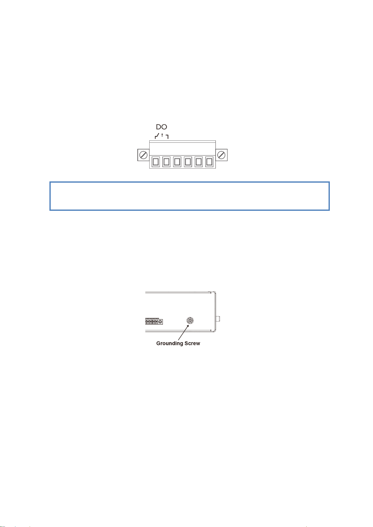
2.4 WIRING THE ALARM RELAY OUTPUT (DO)
The relay output contacts are located on the front panel of the router. The relay output consists of the 2-pin
terminal block connector that used to detect user-configured events. The two wires attached to the fault contacts
form a close circuit when a user-configured event is triggered. If a user-configured event does not occur, the fault
circuit remains open. The fault conditions such as power failure, Ethernet port link break or other pre-defined
events which can be configured in the device. Screw the DO wire tightly after digital output wire is connected.
NOTE: The relay contact only supports 1 A current, DC 24V. Do not apply voltage and current higher than
the specifications.
2.5 CONNECTING THE GROUNDING SCREW
Grounding screw is located on the bottom side of the router. Grounding Screw helps limit the effects of noise due to
electromagnetic interference (EMI) such as lighting or surge protection. Run the ground connection from the ground
screw to the grounding surface prior to connecting devices. And tighten and wire to chassis grounding for better
durability.
12
Page 13

2.6 DIN RAIL MOUNTING
The EN50022 DIN-Rail plate should be already attached to the back panel of the device screwed tightly. If user needs
to reattach the DIN-Rail attachment plate to the device, make sure the plate is situated towards the top, as shown by
the following figures.
To mount the router on DIN Rail track, do the following instruction:
1. Insert the top side of DIN Rail track into the slot of DIN Rail clip.
2. Lightly clip the bottom of DIN-Rail to the track and make sure it attached well.
3. To remove the device from the track, reverse the steps.
13
Page 14

2.7 ANTENNA
WR312G & WR322GR are supported with up to 5 antenna sockets, where 3G/LTE, GPS, and Wi-Fi antennas are
supported. All of the antennas are connected to the router by screwing all the antennas to the SMA connector on the
front panel of the router.
WiF i Antenna
Frequency 2400 ~ 2500 MHz
5150 ~ 5850 MHz
S.W. R <= 2.0 @ 2400 ~ 2500 MHz
<= 2.0 @ 5150 ~ 5850 MHz
The data is tested with 1M cable
Peak Gain 2.5 ± 0.5 dBi @ 2400 ~ 2500 MHz
3.0 ± 0.5 dBi @ 5150 ~ 5850 MHz
Efficiency 70 % @ 2400 ~ 2500 MHz
LTE Antenna
85 % @ 5150 ~ 5850 MHz
Polarization Linear
Impedance 50 Ohm
Connector Type SMA Male Reverse
Operational Temperature - 40 °C ~ +65 °C
Frequency 704 ~ 960 MHz
1710 ~ 2690 MHz
V.S.W.R <= 3.0
Radiation Omni
Gain 2dBi
Polarization Vertical
Impedance 50 Ohm
Connector Type Brass
Operational Temperature - 20 °C ~ +65 °C
NOTE: Please refer to device stick for antenna combination of different models
14
Page 15
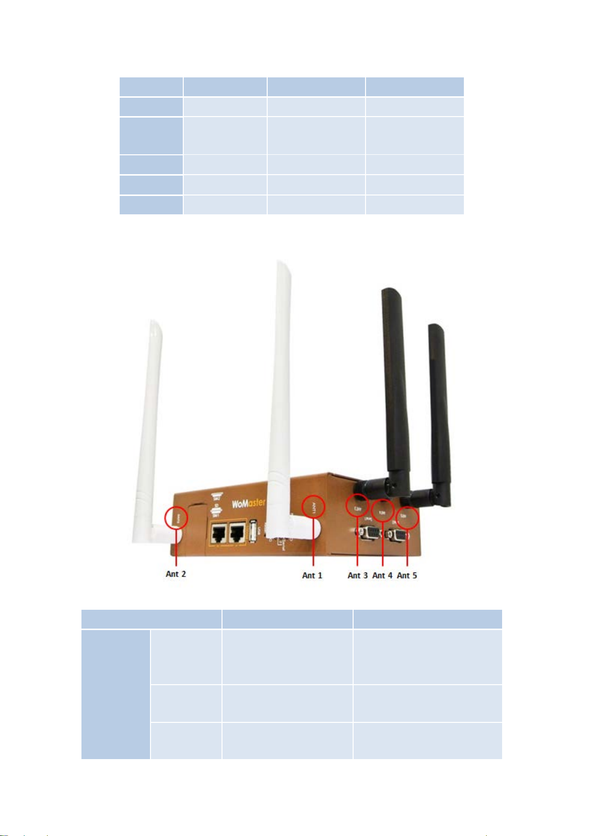
Antenna Placement
Antenna WR312G-LTE WR312G-WLAN WR 322GRWLAN+LTE-
Ant 1 LTE -Main Wi-Fi 1 Wi-Fi 1
Ant 2
LTE Diversity
(GPS by request)
Ant 3 - - LTE -Main
Ant 4 - - GPS
Ant 5 - - LTE -Aux
Check the picture below for the antenna installation.
Wi-Fi 2 Wi-Fi 2
WR312G Radio LED
Radio 1
LED LTE Status WLAN Status
Ra
SIM detected: Green On
SIM not detected: Off
2/3G connection: Green On
Rb
Not 2/3G connection: Off
4G connection: Green On
Rc
Not 4G connection: Off
15
AP: Green On
Disable/Station: Off
Connected: Green Blinking
Reserved
Reserved
Page 16

WR322GR Radio LED
LED LTE Status WLAN Status
AP: Green On
Radio 1
Radio 2
Ra -
Rb - Reserved
Rc - Reserved
SIM detected: Green On
Rd
SIM not detected: Off
4G connection: Green On
2/3G connection: Green
Re
Blinking
Disconnection: Off
Base station
connected: Green Blinking
On for 2 second period
Rf
Base station
disconnected: Green Blinking
Off for 2 second period
Disable/Station: Off
Connected: Green Blinking
-
-
-
2.8 SIM/SD CARD INSTALLATION
SIM Card Slot
The SIM Card Slot is used to insert the cellular card.
WARNING: Be careful when install the SIM Card, wrong installation procedure will cause damage.
Please follow the mechanical print out to install the SIM Card.
WR312G
Micro SD Card Slot
WR312G C Series
WR322GR
WR322GR C Series
The SD Card Slot is installed next to SIM slot. It is used for field diagnostic data logging/option for storage per
demand.
16
Page 17

3. WEB MANAGEMENT CONFIGURATION
To access the management interface, WoMaster router has two ways access mode through a network; they are web
management and telnet management. Web interface management is the most common way and the easiest way to
manage a network, through web interface management, a router interface offering status information and a subset
of device commands through a standard web browser. If the network is down, another alternative to access the
management interface can be used. The alternative way is by using telnet management which is offer configuration
way through CLI Interface. This manual describes the procedures for Web Interface and how to configure and
monitor the managed router only.
PREPARATION FOR WEB INTERFACE MANAGEMENT
WoMaster provides Web interface management that allows user through standard web-browser such as Microsoft
Internet Explorer, or Mozilla, or Google Chrome, to access and configure the router management on the network.
1. Plug the DC power to the router and connect router to computer.
2. Make sure that the router default IP address is 192.168.10.1.
3. Check that PC has an IP address on the same subnet as the router. For example, the PC and the router
are on the same subnet if they both have addresses that start 192.168.10.x (Ex: 192.168.10.2). The subnet
mask is 255.255.255.0.
4. Open command prompt and ping 192.168.10.1 to verify that the router is reachable.
5. Launch the web browser (Internet Explorer or Mozilla Firefox or Google Chrome) on the PC.
6. Type http://192.168.10.1
appear.
7. Type user name and the password. Default user name: admin and password: admin. Then click Login.
(or the IP address of the router). And then press Enter and the login page will
In this Web management for Featured Configuration, user will see all of WoMaster Cellular Router’s various
configuration menus at the left side from the interface. Through this web management interface, user can configure,
monitoring, and set the administration functions. The whole information used web management interface to
17
Page 18

introduce the featured functions. User can use all of the standard web-browser to configure and access the router
on the network.
Following topics are covered in this chapter:
3.1 System
3.2 Ethernet Port
3.3 Redundancy
3.4 Serial
3.5 Cellular
3.6 GPS
3.7 Wireless LAN
3.8 Security
3.9 Routing
3.10 Warning
3.11 Diagnostics
3.12 IoT
3.13 Backup and Restore
3.14 Firmware Upgrade
3.15 Reset to Defaults
3.16 Save
3.17 Logout
3.18 Reboot
3.19 WoMaster MIB
18
Page 19
3.1 SYSTEM
When the user login to the router, user will see the system section appear. This section provides all the basic setting
and information or common setting from the router that can be configured by the administrator.
Following topics are included:
3.1.1 Information
3.1.2 Login Setting
3.1.3 Network IP
3.1.4 Date and Time
3.1.5 DHCP Server
3.1.1 INFORMATION
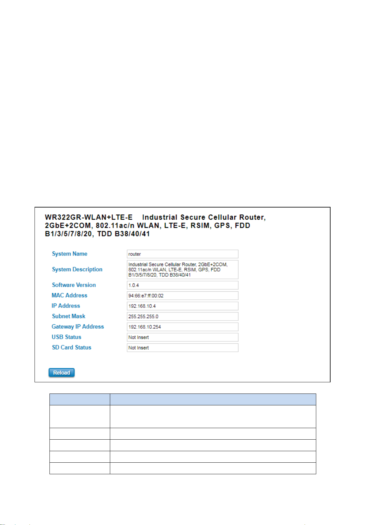
Information section, this section shows the basic information from the router to make it easier to identify different
router that is connected to User network and also it shows the Cellular Status and LAN Settings information. The
figure below shows the interface of the Information section.
The description of the Information’s interface is as below:
TERMS DESCRIPTION
System Name Default: router
Set up a name to the device.
System Description Display the name of the product.
Software Version Display the firmware latest version that installed in the device.
MAC Address Display the hardware’s MAC address that assigned by the manufacturer.
IP Address Display the IP Address of the device
19
Page 20
Subnet Mask Display the subnet mask of the device
Gateway IP Address Display the gateway IP Address of the device
USB Status Display the USB port status when the USB is plugged or unplugged.
SD Card Status Display the SD Card port status when the SD Card is inserted or not inserted.
3.1.2 LOGIN SETTING
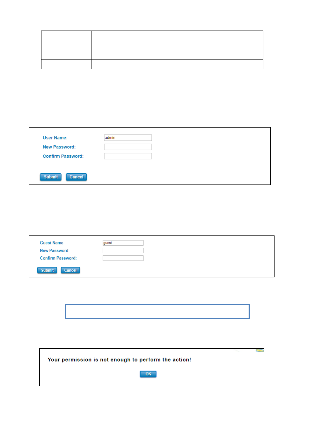
WoMaster’ router supports Login Setting that has several authentication methods. It is supported with TACACS+,
Radius, and Multi-User Authentication. This Login Setting consists of two level, admin and guest. Where the admin
level, it has the privilege to read and write and for the guest level the privilege is read only. Below is the Login
Setting section for admin level.
With the Name default setting is admin and the authority allow user to configure all of configuration parameters.
The Login Setting interface describes how to configure the system username and password for the web management
login.
To change the Name and Password, user just needs to input a new Name and New Password then confirm the
new password in this section. Try to re-login with the new User Name and Password.
Below is the interface for guest level.
With the Name default setting is guest and the authority allow user to read only all of configuration parameters.
NOTE: For security consideration, please change the password after first log in.
When user try to change the configuration, message will appear if user is not permitted to configure the
configuration. Below is the interface.
20
Page 21
The description of the Login Setting interface is as below:
TERMS DESCRIPTION
User Name/ Guest Name Default: admin/guest
Key in new username here.
New Password Key in new password here.
Confirm Password Re-type the new password again to confirm it.
After finishing configure the Username and Password, click on Submit to apply the configuration. Don’t forget to
Save the configuration.
Authentication Mode
The authentication can be performed locally and remotely using Radius or TACACS+ authentication server. It has 5
authentication modes which are Local, RADIUS, RADIUS->Local, TACPLUS, and TACPLUS->Local. The default
authentication method is Local method, where it works for multi user authentication that has been explained above.
RADIUS
The Remote Authentication Dial-In User Service (RADIUS) protocol was developed by Livingston Enterprises as an
access server authentication and accounting protocol. The RADIUS server can support a variety of methods to
authenticate a user. When it is provided with the username and original password given by the user, it can support
PPP, PAP or CHAP, UNIX login, and other authentication mechanisms. Below is the RADIUS and RADIUS to Local
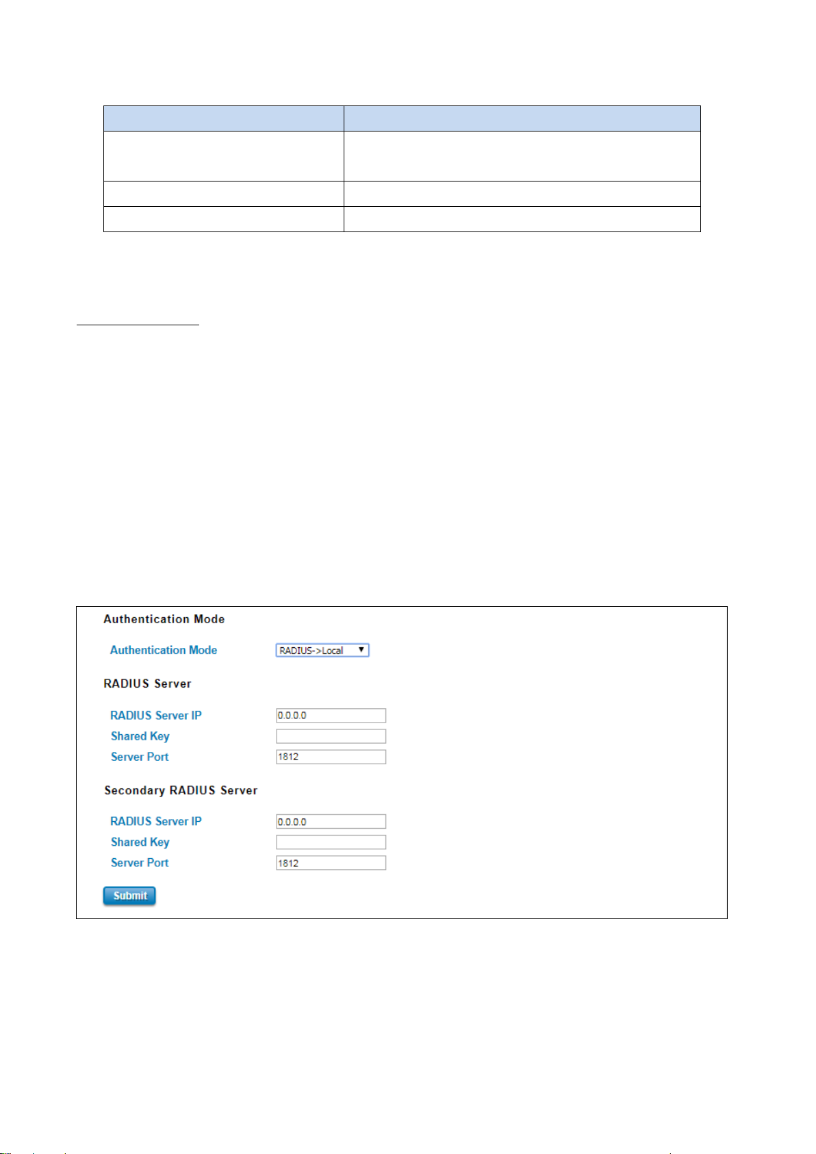
authentication mode interface. For the RADIUS to Local mode, the authentication will try remote authentication first,
falling back to local authentication mode if remote mode fails.
How to set up a RADIUS server:
a. Enter the IP address of the RADIUS server in Server IP Address
b. Enter the Shared Secret of the RADIUS server
c. Enter the Server port if necessary, by default RADIUS server listens to port 1812
d. Click Submit
21
Page 22
configured with the same shared key. Shared key also verify that the
The description of the RADIUS Authentication interface is as below:
TERMS DESCRIPTION
RADIUS Server IP Radius Server IP Address
Shared Key Shared key are used to verify that RADIUS messages, with the exception of
the Access-Request message, are sent by a RADIUS-enabled device that is
RADIUS message has not been modified in transit (message integrity).
Server Port Set communication port of an external RADIUS server as the authentication
database. The general value is 1812
TACACS+
The Terminal Access Controller Access Control System (TACACS+) security protocol is a recent protocol developed by
Cisco. It provides detailed accounting information and flexible administrative control over the authentication and
authorization processes. TACACS+ allows for a single access control server (the TACACS+ daemon) to provide
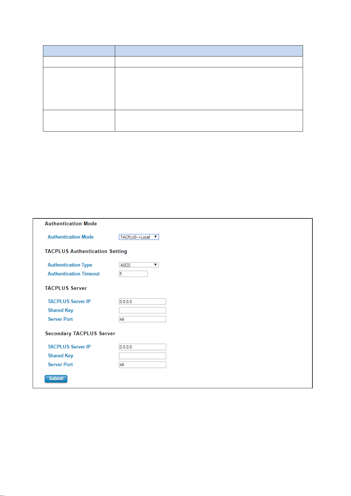
authentication, authorization, and accounting services independently. Below is the interface for TACPLUS and
TACPLUS to Local authentication mode. For the TACPLUS to Local mode, the authentication will try remote
authentication first, falling back to local authentication mode if remote mode fails or cannot be reached.
How to set up a TACACS+ server:
a. Select the Authentication Type.
b. Enter the Authentication Timeout in seconds.
c. Enter the IP address of the TACACS+ server in Server IP Address.
d. Enter the Shared Secret of the TACACS+ server.
e. Enter the Server port if necessary, by default TACACS+ server listens to port 49.
22
Page 23

and the TACACS+ server. The shared key must match the encryption used
f. Click Submit
The description of the TACACS+ Authentication interface is as below:
TERMS DESCRIPTION
Authentication Type Default: ASCII
Select the authentication type to authenticate to the server.
Authentication Timeout Default: 5
The maximum number of seconds allowed establishing a TCP connection
between the device and the TACACS+ server. If the server cannot be
reached within the limit time, and it will directly change to Local. This
configuration is applied to TACPLUS->Local mode only.
TACPLUS Server IP TACACS+ Server IP Address
Shared Key Specifies the shared key for TACACS+ communications between the device
on the TACACS+ server.
Server Port Set communication port of an external TACACS+ server as the
authentication database. The general value is 49
23
Page 24
3.1.3 NETWORK SETTING
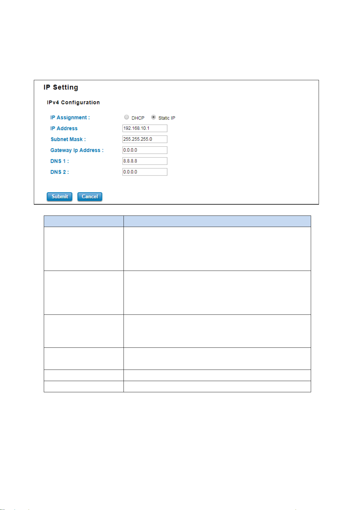
The Network Setting section allows users to configure both IPv4 values for management access over the network.
WoMaster’ router supports IPv4, and can be managed through either of these address types. Below is the IP Setting
interface for Bridge Mode.
The description of the columns is as below:
TERMS DESCRIPTION
IP Assignment User can select to DHCP or Static IP to activate the function.
DHCP: Select DHCP to activate DHCP Client Function, no need to assign IP
Address and received IP Address from DHCP Server.
Static IP: Select Static IP to configure the IP configuration manually
IP Address Default: 192.168.10.1
Set up the IP address reserved by User network for User device. If DHCP
Client function is enabled, no need to assign an IP address to device as it
will be overwritten by DHCP server and shown here.
Subnet Mask Default: 255.255.255.0
Assign the subnet mask for the IP address here. If DHCP Client function is
enabled, no needs to assign the subnet mask.
Gateway IP Address Default: 0.0.0.0.
Assign the gateway for the device here.
DNS 1 Specifies the IP address of the DNS server 1 that used in user network.
DNS 2 Specifies the IP address of the DNS server 2 that used in user network.
24
Page 25
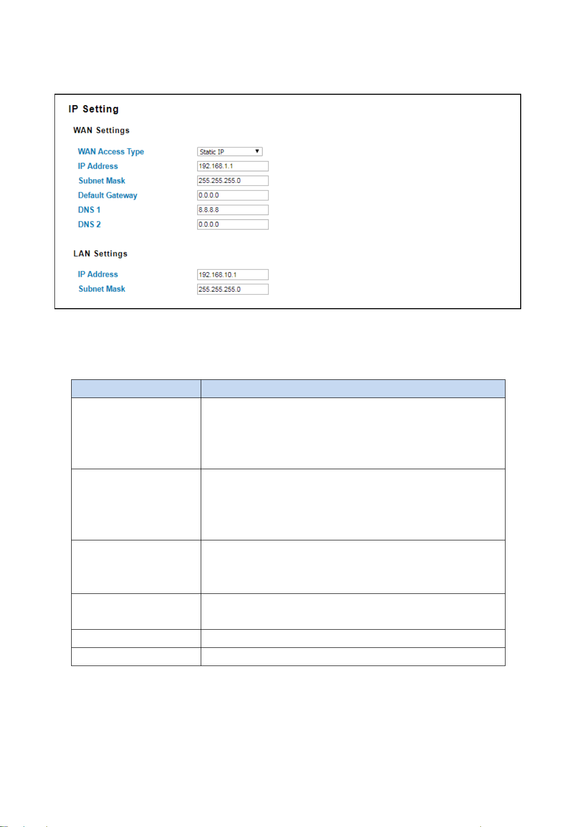
And below is the IP Setting interface for the Router Mode where it supports with the WAN port on port 1. User can
configure the WAN Settings.
The IPv4 Configuration includes the router’s IP address and subnet mask, as well as the IP address of the default
gateway. In addition, input cells are provided for the IP addresses of a 1st and 2nd DNS server. Configure the
managed router’s IP settings. The figure above shows the user interface of IPv4 Configuration.
The description of the columns is as below:
TERMS DESCRIPTION
WAN Access Type User can select to DHCP Client or Static IP to activate the function.
DHCP Client: Select DCHP Client to activate DHCP Client Function, no
need to assign IP Address and received IP Address from DHCP Server.
Static IP: Select Static IP to configure the IP configuration manually
IP Address Default: 192.168.1.1
Set up the IP address reserved by User network for User device. If DHCP
Client function is enabled, no need to assign an IP address to device as it
will be overwritten by DHCP server and shown here.
Subnet Mask Default: 255.255.255.0
Assign the subnet mask for the IP address here. If DHCP Client function is
enabled, no needs to assign the subnet mask.
Gateway IP Address Default: 0.0.0.0.
Assign the gateway for the device here.
DNS 1 Specifies the IP address of the DNS server 1 that used in user network.
DNS 2 Specifies the IP address of the DNS server 2 that used in user network.
Proxy ARP
Proxy ARP is a technique in which one host, usually a router answers ARP requests intended for another node located
on another network. The router or "faking" its identity or pretends to be the target of the ARP requests by sending
ARP responses that associate its own MAC address with the real (destination) node’s IP address. The router acts as a
25
Page 26
proxy and takes responsibility for routing packets to the real destination. Proxy ARP can help machines on a subnet
reach remote subnets without the need to configure routing or a default gateway.
When Proxy ARP is enabled, if the router receives an ARP request for which it has a route to the target (destination)
IP address, the router responds by sending a Proxy ARP reply packet containing its own MAC address. The host that
sent the ARP request then sends its packets to the router, which forwards them to the intended host.
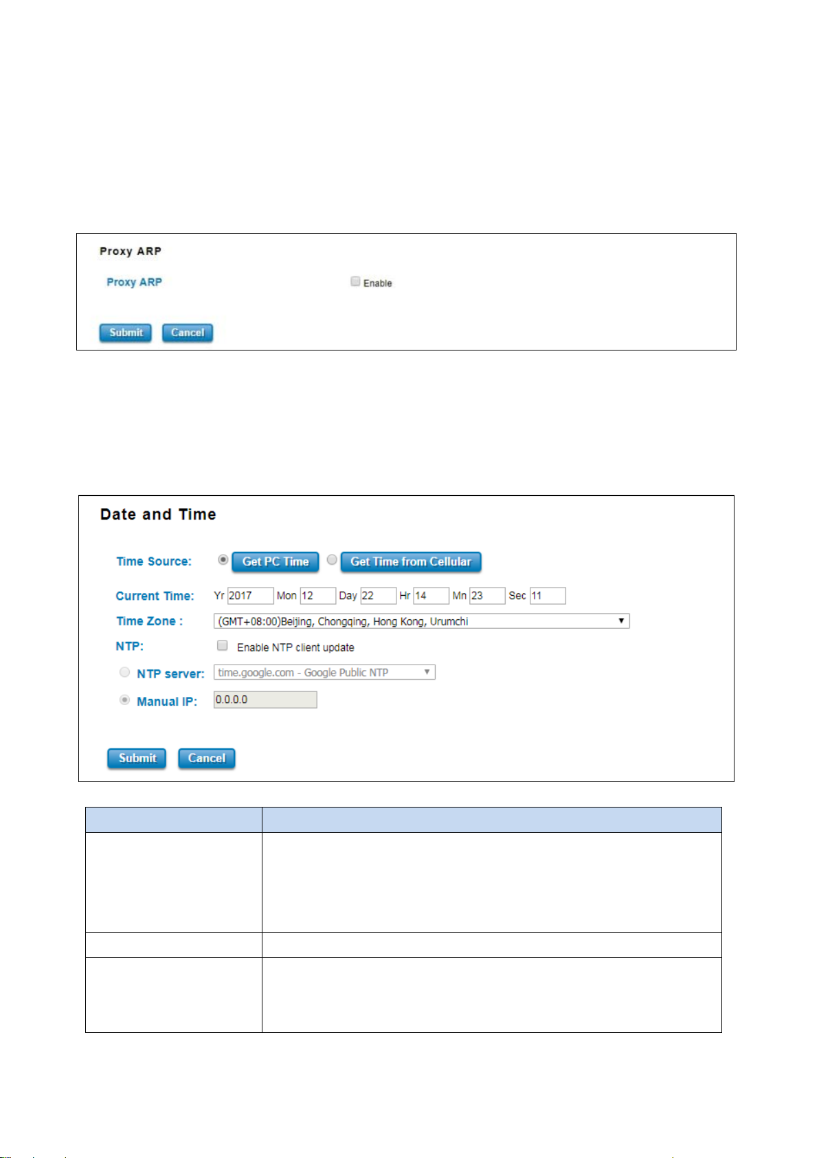
Below is the interface.
Check the box to enable the function of Proxy ARP.
3.1.4 DATE AND TIME
The WoMaster router has a time calibration function based on information from an NTP server or user specified time
and date, allowing functions such as automatic warning emails to include a time and date stamp.
The description of the columns is as below:
TERMS DESCRIPTION
Current Time User can configure time by input it manually. User also can click the Get PC
Time or Get Time from Cellular to get the time setting.
Get PC Time: get the time the PC
Get Time from Cellular: get the time from the cellular network.
Time Zone Choose the Time Zone section to adjust the time zone based on the user area.
NTP Enable NTP Client update by checking this box.
Select the time server from the NTP Server dropdown list or select Manual IP
to manually input the IP address of available time server.
26
Page 27
*Make sure that the device also has the internet connection.
After finished configuring, click on Submit to activate the configuration.
3.1.5 DHCP SERVER
DHCP Server Setting
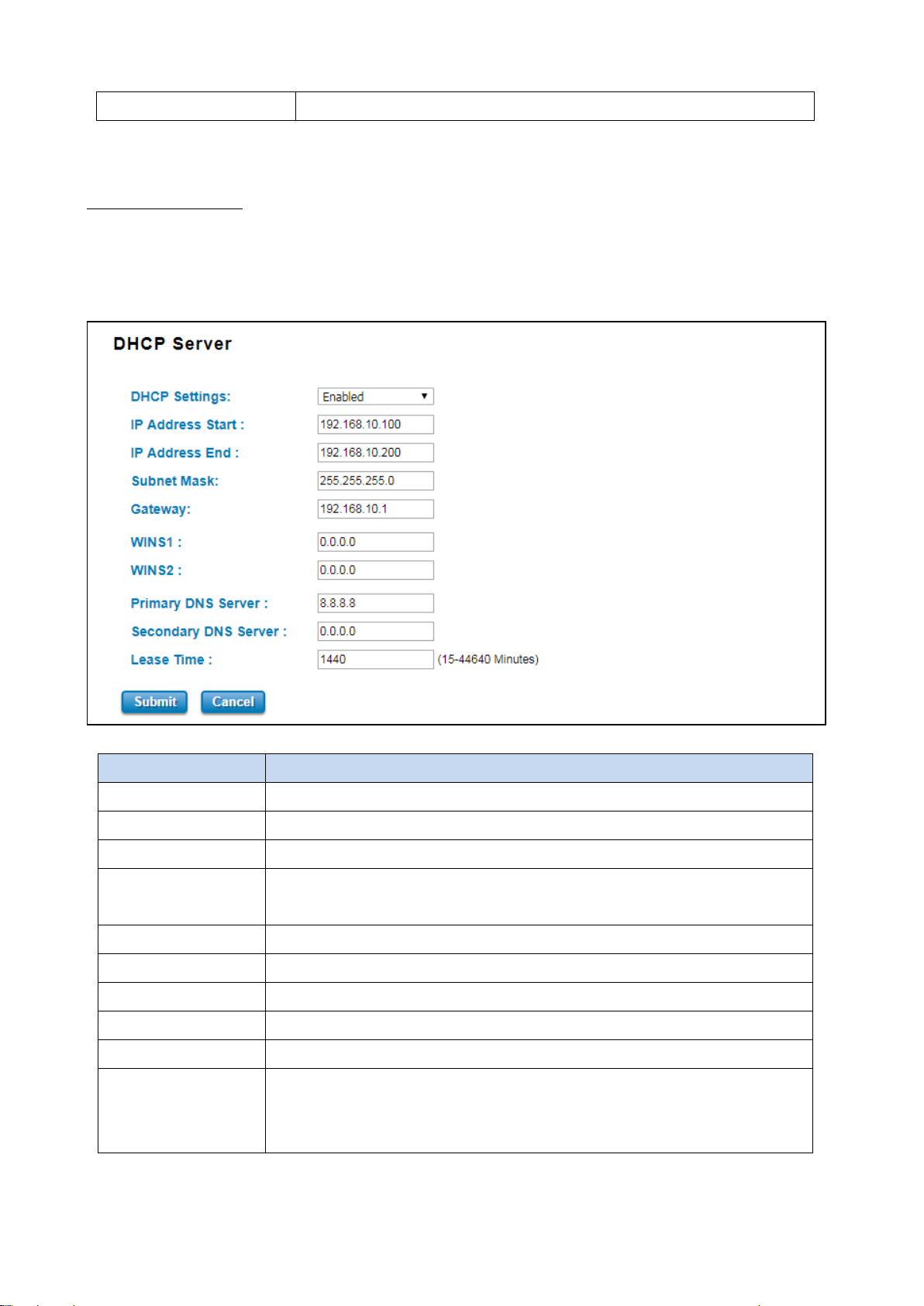
WoMaster router has DHCP Server Function that will provide a new IP address to DHCP Client. After enabling DHCP
Server function, set up the Network IP address for the DHCP server IP address, Subnet Mask, Default Gateway
address and Lease Time for client. Below is the DHCP Server Setting interface
The description of the columns is as below:
TERMS DESCRIPTION
DHCP Setting Select to Enable or Disable to activate and deactivate DHCP Server function.
IP Address Start Assign the IP Address Start range.
IP Address End Assign the IP Address End range.
Subnet Mask Default: 255.255.255.0
Assign the subnet mask for the IP address here for DHCP Server.
Gateway Assign the gateway for the router here for DHCP Server.
WIN S1 Enter WINS Server 1 IP address
WIN S2 Enter WINS Server 2 IP address
Primary DNS Server Enter Primary DNS Server that used in user network.
Secondary DNS Server Enter Secondary DNS Server that used in user network.
Lease Time Default: 1440
The maximum length of time for the IP address lease. Enter the Lease time in
minutes. (Lease Time range: 15-44640 minutes)
27
Page 28
The DHCP Server will automatically assign an IP address to the computers on the LAN/private network. Be sure to set
user computers to be DHCP clients by setting their TCP/IP settings to “Obtain an IP Address Automatically.” When
user turns the computers on, they will automatically load the proper TCP/IP settings provided by the router. If User
manually assigns IP addresses to User computers or devices, make sure the IP addresses are outside of this range or
User may have an IP conflict. After finished configuring, click on Submit to activate the configuration.
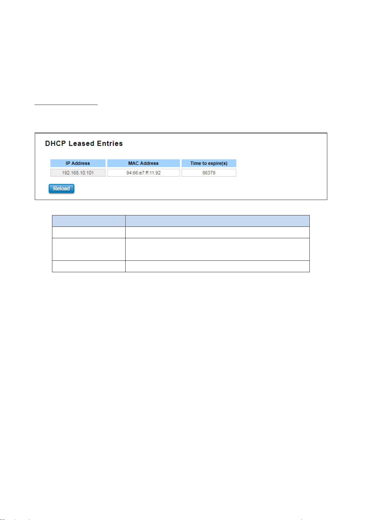
DHCP Leased Entries
The figure below shows the DHCP Leased Entries. It will show the MAC and IP address that was assigned by router.
Click the Reload button to refresh the list.
The description of the columns is as below:
TERMS DESCRIPTION
IP Address IP address that was assigned by router.
MAC Address The MAC Address of the network interface that was used to acquire
the lease.
Time to expire(s) Remains time for the IP address from DHCP Server leased.
28
Page 29
3.2 ETHERNET PORT
Ethernet Port section is used to access the port configuration and rate limit control. It also allows User to view port
status and port trunk information.
Following items are included in this group:
3.2.1 Ethernet Status
3.2.2 Ethernet Setting
3.2.3 Traffic Control
3.2.1 ETHERNET STATUS
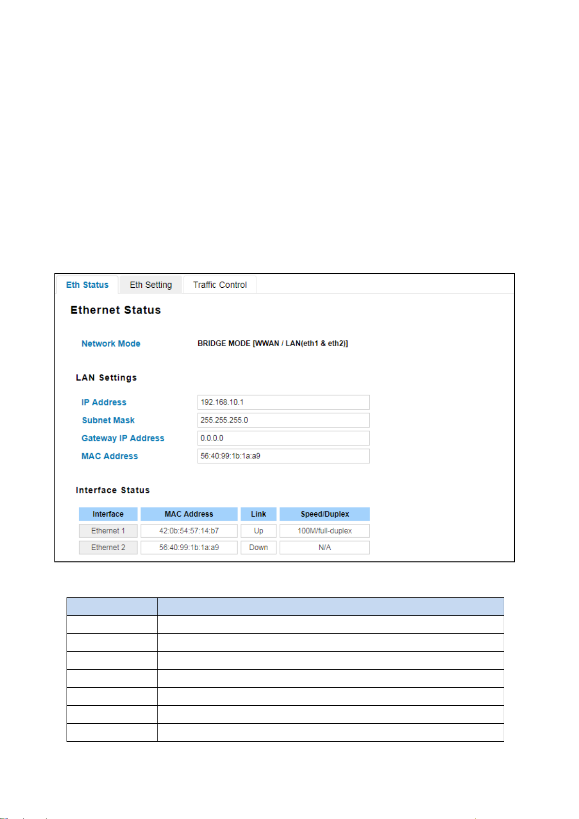
Ethernet Status section allows users to see the current status from the Ethernet such as Network Mode, LAN Settings,
and also the Interface Status.
The description of the columns is as below:
TERMS DESCRIPTION
Network Mode Shows network mode from the router (Bridge or Router)
IP Address Display the IP address reserved by User network for User router
Subnet Mask Display the subnet mask for the IP address.
Gateway IP Address Display the gateway that assigned to the router.
MAC Address Display the hardware’s MAC Address that assigned by the manufacturer.
Interface Display the Ethernet interface
MAC Address Display the port MAC Address
29
Page 30
Link Display the Ethernet status, whether it is Link Up or Link Down.
Speed/Duplex Default: N/A
Show the Speed/Duplex for each port, such as 10 full,10 half,100 full,100 half mode
for Giga Ethernet Port 1~2 (ge1~ge2)
Click on Reload to update the information.
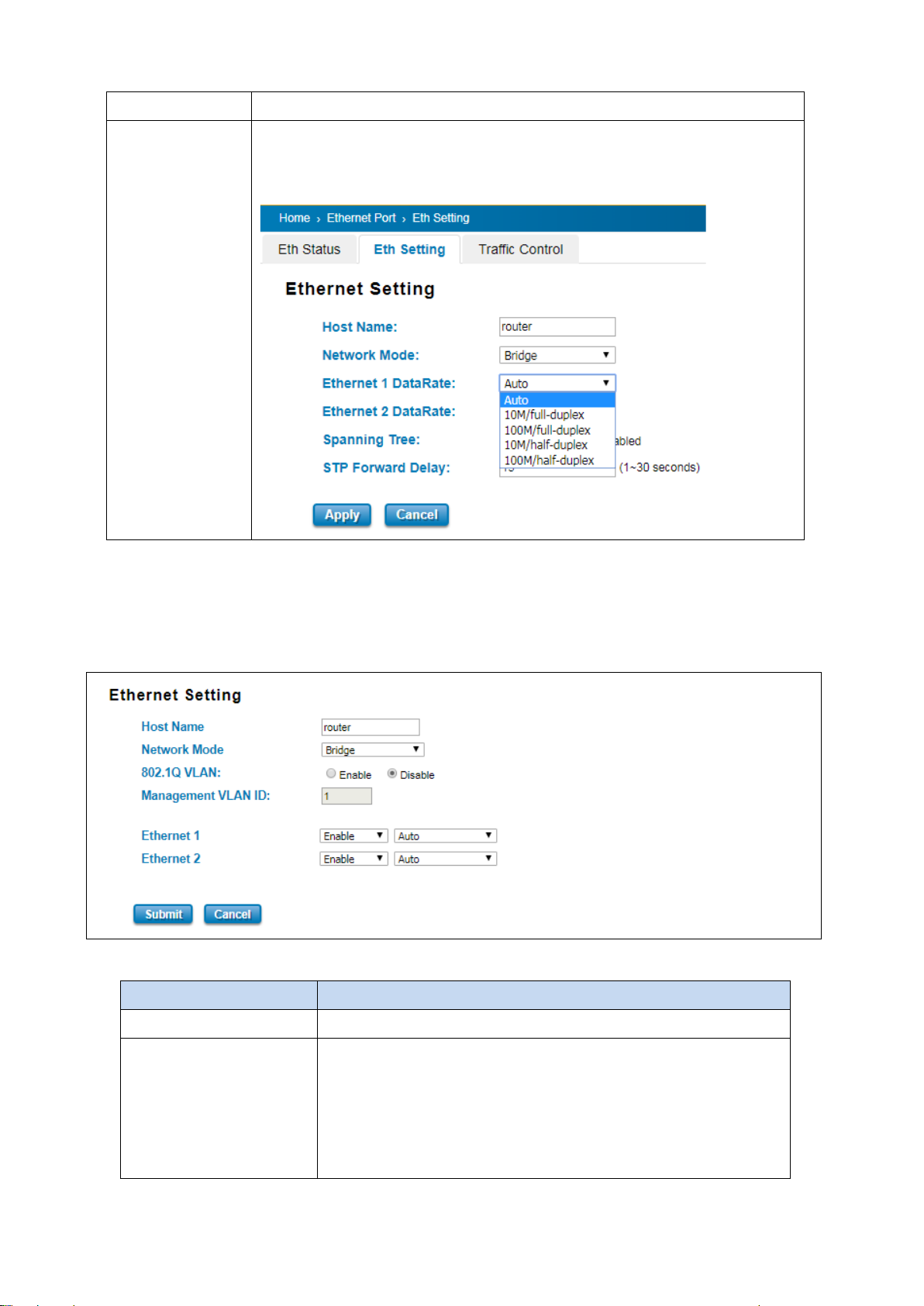
3.2.2 ETHERNET SETTING
Use this page to configure the Ethernet setting such as the Host Name, Network Mode and the speed / duplex for the
Ethernet port.
The description of the Ethernet Setting page is as below:
TERMS DESCRIPTION
Host Name Give a name to identify the device.
Network Mode Default: Bridge
Select Bridge mode or Router mode depends on the application.
When the Router mode is selected, then the device will change to
router mode and the interface for port 1 would be WAN interface and
port 2 would be LAN interface.
30
Page 31
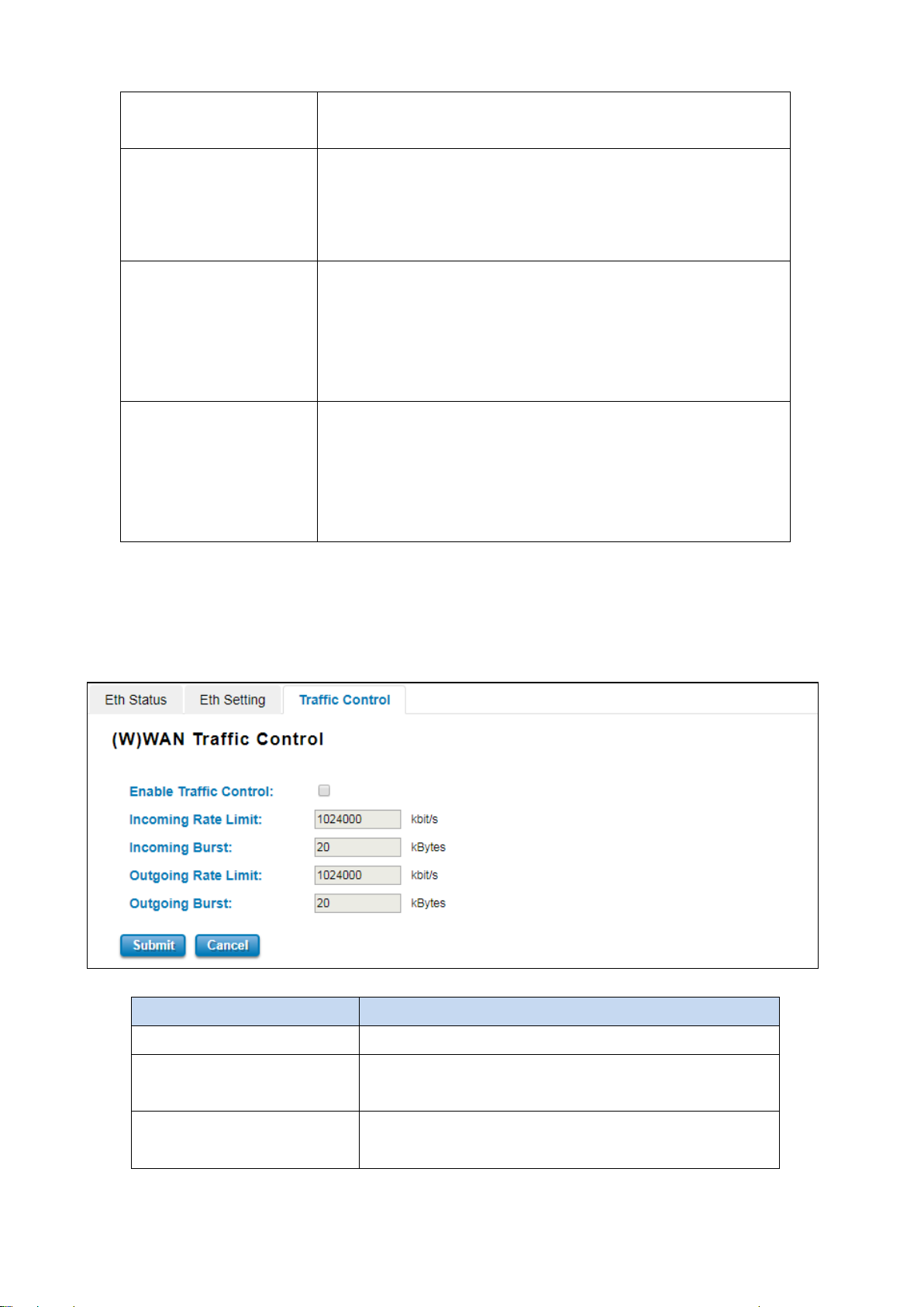
802.1 VLAN Default: Disable
Choose enable to activate the function.
Management VLAN Default: 1
The switch supports management VLAN. The management VLAN ID is
the VLAN ID of the CPU interface so that only member ports of the
management VLAN can ping and access the switch.
Ethernet 1 Default: Enable
Default: Auto / Auto-Negotiation
Configure the Speed/Duplex of the port Ethernet 1. Users can set the
bandwidth of each port as Auto-negotiation, 100 full, 100 half, 10 full,
10 half mode.
Ethernet 2 Default: Enable
Default: Auto / Auto-Negotiation
Configure the Speed/Duplex of the port Ethernet 2. Users can set the
bandwidth of each port as Auto-negotiation, 100 full, 100 half, 10 full,
10 half mode.
Click Submit to apply the configuration that just made.
3.2.3 TRAFFIC CONTROL
Traffic control is a form of flow control used to enforce a strict bandwidth limit at a port. User can configure
separate Incoming Outgoing rate limits and burst
The description of the columns is as below:
TERMS DESCRIPTION
Enable Traffic Control Check the box to activate the function
Incoming Rate Limit Default: 1024000 kbit/s
Incoming Burst Default: 20 kBytes
Set the maximum incoming rate.
Set the maximum incoming burst.
31
Page 32
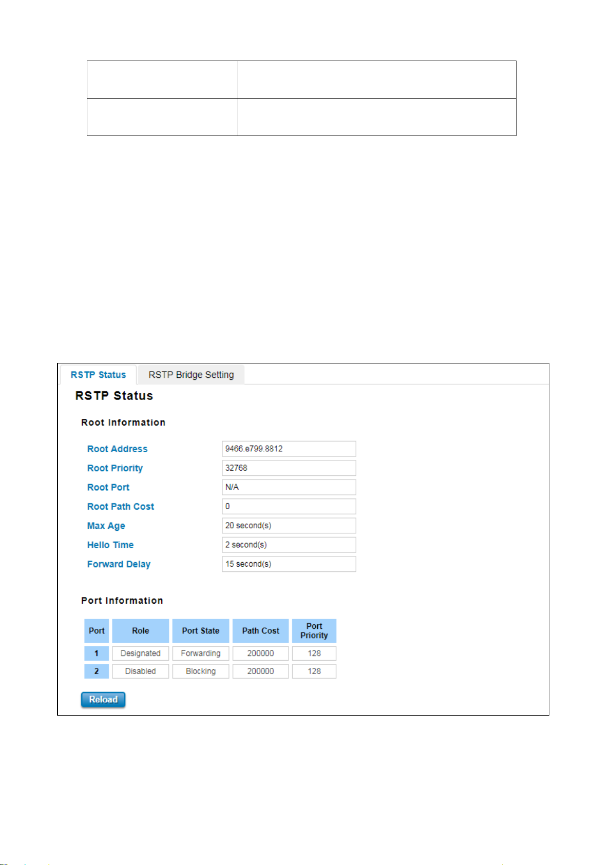
Outgoing Rate Limit Default: 1024000 kbit/s
Set the maximum outgoing rate.
Outgoing Burst Default: 20 kBytes
Set the maximum outgoing burst.
Click on Submit to apply the configuration.
3.3 REDUNDANCY
Redundancy role of the network is to help protect critical links against failure, protects against network loops, and
keeps network downtime at a minimum. Sustainable, uninterrupted data communication network is critical for
industrial applications. Network Redundancy allows user to set up redundant loops in the network to provide a
backup data transmission route in the event that a cable is inadvertently disconnected or damaged. This switch
supports Spanning Tree Protocol (STP) and Rapid Spanning Tree Protocol (RSTP). This is a particularly important
feature for industrial applications, since it could take several minutes to locate the disconnected or severed cable.
3.3.1 RSTP STATUS
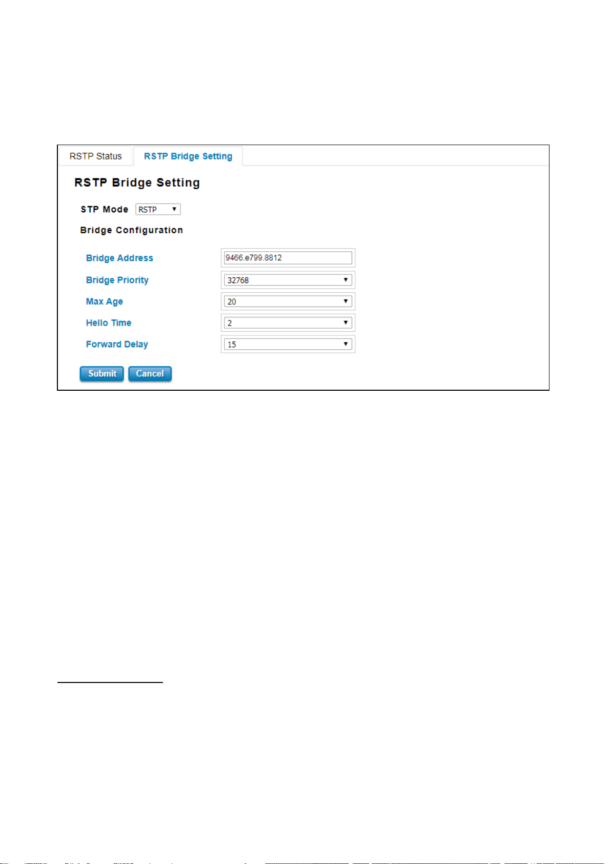
This page allows user to see the information of the root switch and port status.
Root Information: User can see root Address, Root Priority, Root Port, Root Path Cost and the Max Age, Hello Time
and Forward Delay of BPDU sent from the root switch.
Port Information: User can see port number, port Role, Port State, Path Cost and Port Priority.
32
Page 33
3.3.2 RSTP BRIGDE SETTING
The STP mode includes the STP, RSTP and Disable. User can select the STP mode for user system first. The default
mode is RSTP enabled. After user selects the STP or RSTP mode; user should continue to configure the global Bridge
parameters for STP and RSTP.
Spanning Tree Protocol (STP)
STP is a Layer 2 link management protocol that provides path redundancy while preventing loops in the network. For
a Layer 2 Ethernet network to function properly, only one active path can exist between any two stations.
Spanning-tree operation is transparent to end stations, which cannot detect whether they are connected to a single
LAN segment or a switched LAN of multiple segments.
Rapid Spanning Tree Protocol (RSTP)
If the destination from a switch is more than one path, it will lead to looping condition that can generate broadcast
storms in a network. The spanning tree was created to combat the negative effects of message loops in switched
networks. A spanning tree algorithm is used to automatically sense whether a switch has more than one way to
communicate with a node. It will then select the best path, and block the other path. Spanning Tree Protocol (STP)
introduced a standard method to accomplish this. Rapid Spanning Tree Protocol (RSTP) was adopted and represents
the evolution of STP, providing much faster spanning tree convergence after a topology change.
Bridge Configuration
Bridge Address: This shows the switch’s MAC address.
Bridge Priority (0-61440): RSTP uses bridge ID to determine the root bridge, the bridge with the highest bridge ID
becomes the root bridge. The bridge ID is composed of bridge priority and bridge MAC address. So that the bridge
with the highest priority becomes the highest bridge ID. If all the bridge ID has the same priority, the bridge with the
lowest MAC address will then become the root bridge.
33
Page 34

The bridge priority value must be in multiples of 4096. A device with a lower number has a higher
NOTE:
1.
bridge priority.
2. The Web GUI allows user selects the priority number directly. This is the convenient of the GUI design.
When user configures the value through the CLI or SNMP, user may need to type the value directly.
Please follow the n x 4096 rules for the Bridge Priority.
Max Age (6-40): Enter a value from 6 to 40 seconds here. This value represents the time that a bridge will wait
without receiving Spanning Tree Protocol configuration messages before attempting to reconfigure.
Hello Time (1-10): Enter a value from 1 to 10 seconds here. This is a periodic timer that drives the switch to send out
BPDU (Bridge Protocol Data Unit) packet to check current STP status. The root bridge of the spanning tree topology
periodically sends out a Hello message to other devices on the network to check if the topology is normal. The Hello
Time is the amount of time the root has waited during sending hello messages.
Forward Delay Time (4-30): Enter a value between 4 and 30 seconds. This value is the time that a port waits before
changing from Spanning Tree Protocol learning and listening states to forwarding state.
Once user has completed user configuration, click on Submit to apply user settings.
NOTE: User must follow the rule to configure Hello T ime, Forwarding Delay, and Max Age
parameters.
2× (Forward Delay Time – 1 sec) ≥ Max Age Time ≥ 2 × (Hello Time value + 1 sec)
34
Page 35
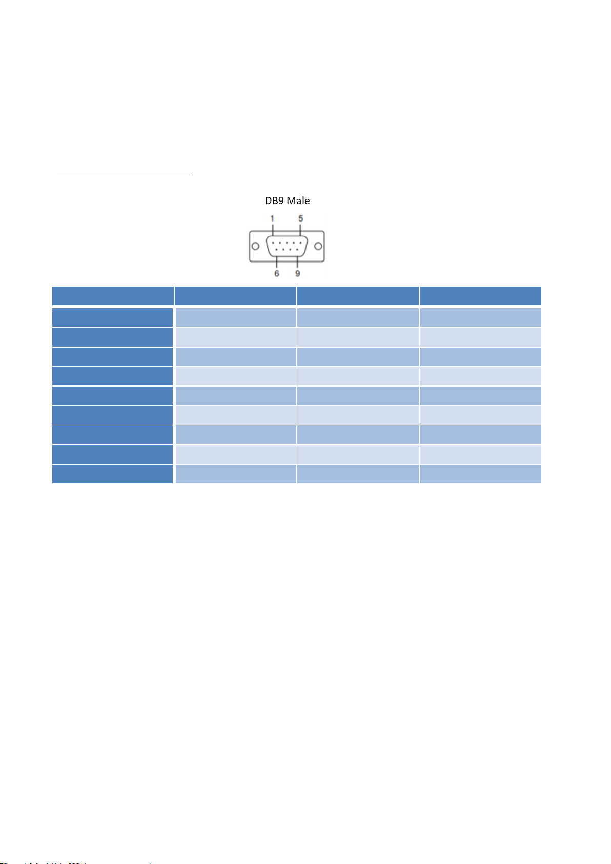
3.4 SERIAL
This router also equipped with two serial ports which are RS232/422/485 ports that able to connect to local serial
devices. And these serial ports support TCP Server, TCP Client, and UDP Listening. From the web management
interface, it has two configuration pages for Serial 1 and Serial 2.
Below is the pin definition
Pin RS232 RS485-4w/422 RS485-2w
1 DCD TX- Data-
2 TXD RX+ -
3 RXD TX+ Data+
4 DSR - -
5 GND GND -
6 DTR RX- -
7 CTS - -
8 RTS - -
9 RI - -
RS-232 is the most common serial interface and used to ship as a standard component on most Windows-compatible
desktop computers. Now it is more common to use RS-232 over USB using a converter. RS-232 only allows for one
transmitter and one receiver on each line. RS-232 also uses a Full-Duplex transmission method.
RS422 is an improved version of RS232, it uses twisted pair cable to reduce the noise, and it uses signaling balancing
to transmit data, so what is signal balanced – It uses a voltage-difference between the two lines as an indication of
the signal value, with this method the data is able to transmit for longer distance with faster data rates, with RS422
the data can transmit up to 10 Mbps at 50 feet or 100 Kbps at 4000 feet. RS422 is capable of multi-drop capability, it
limits up to 10 slaves in the data line.
RS-485 is a superset of RS-422 and expands on the capabilities. RS-485 was made to address the multi-drop limitation
of RS-422, allowing up to 32 devices to communicate through the same data line. Both RS-485 and RS-422 have
multi-drop capability, but RS-485 allows up to 32 devices and RS-422 has a limit of 10.
35
Page 36
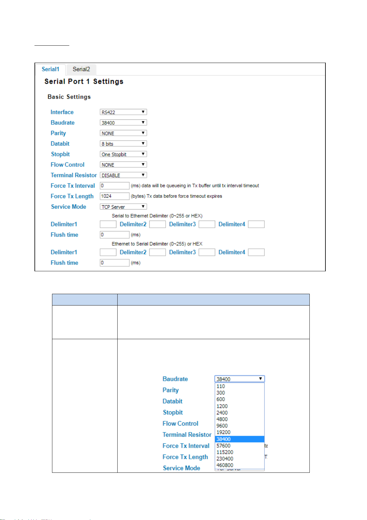
Serial 1 & 2
This configuration page is an interface to configure the serial setting.
The description of the columns is as below:
TERMS DESCRIPTION
Interface Default : RS422
Choose and change the interface type from the drop down list. The serial
port supports the RS232, RS422, RS485-2w, and RS485-4w.
Baudrate Default: 38400
Serial baud rate, a speed measurement of communication. It indicates the
number of bit transfers per second.
36
Page 37

For even and odd parity, the s erial por t will set the parity bit (the last b it aft er
data bits, but simply sets the parity bit high for marked parity or low for
The stop bit follows the data and parity bits in serial communication. It
Parity Default: NONE
Set parity bit of serial data.
the data bits) to a value to ensure that the transmission has an even or odd
number of logic high bits. Mark and space parity does not actually ch ec k th e
spaced parity.
Databit Default: 8 bits
Indicates the number of bits in a transmitted data package.
Stopbit Default: One Stopbit
indicates the end of transmission.
Flow Control Default: NONE
Flow control manages data flow between devices in a network to ensure
it is processed efficiently. Too much data arriving before a device is
prepared to manage it causes lost or retransmitted data.
Terminal Resistor Default: Disable
Enable to prevent serial signal reflection.
Force TX Interval Default: 0 (ms)
Force TX interval time is to specify the timeout when no data has been
transmitted and queue data before the time interval is expired.
Force TX Length Default: 1024 (bytes)
To specify the length of the data before Force timeout expires.
Service Mode Choose TCP Server, TCP Client, and UDP listening.
Serial to Ethernet Delimiter: User can define max. 4 delimiters (0~255, Hex) for each way.
The data will be held until Flush Time is expired. 0 means disable. The
factory default is 0.
Flush Time: The received data will be queued in the buffer until all the
delimiters are matched. When the Flush Time is expired the data will be
sent.
Ethernet to Serial Delimiter: User can define max. 4 delimiters (0~255, Hex) for each way.
The data will be held until Flush Time is expired. 0 means disable. The
factory default is 0.
Flush Time: The received data will be queued in the buffer until all the
37
Page 38
TERMS
DESCRIPTION
When serial port stops data transmission for a defined period of
disabled this setting (default). If Multilink is configured, only the
delimiters are matched. When the Flush Time is expired the data will be
sent.
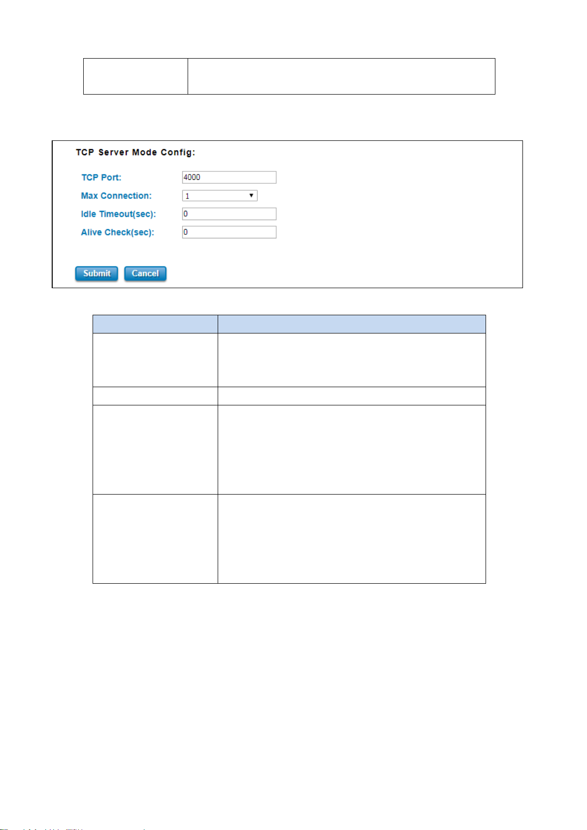
The other section from this Serial page is TCP Server Mode Config. This page allows user to configure the basic
settings of TCP Server Mode.
The description of the columns is as below:
TCP Port Default: Serial 1 – 4000, Serial 2 - 4002
Assign the available TCP port number. The port number of TCP
Server and TCP Client should be the same.
Max Connection Configures the maximum connection number from 1 to 5.
Idle Timeout (sec)
time (Idle Timeout), the connection will be closed and the port
will be freed and re-try for connection with other hosts. Zero is
first host connection is effective for this setting.
Alive Check (sec) The device will send a TCP alive check package in each defined
time interval (Alive Check) to remote host to test the TCP
connection. If the TCP connection is not alive, the connection
will be closed and the port will be freed for other hosts. If user
sets it as zero, it means disable this setting.
38
Page 39
by choosing this mode, the redundancy mode
WAN connection has a
ncy mode
3.5 CELLULAR
This Cellular page provides the Cellular Status; configure Cellular Setting, and configure SIM Setting. WoMaster
Industrial Router is supported with redundant SIM and Dual SIM Card; user can choose SIM1 or SIM2 for the main
SIM Card.
3.5.1 CELLULAR STATUS
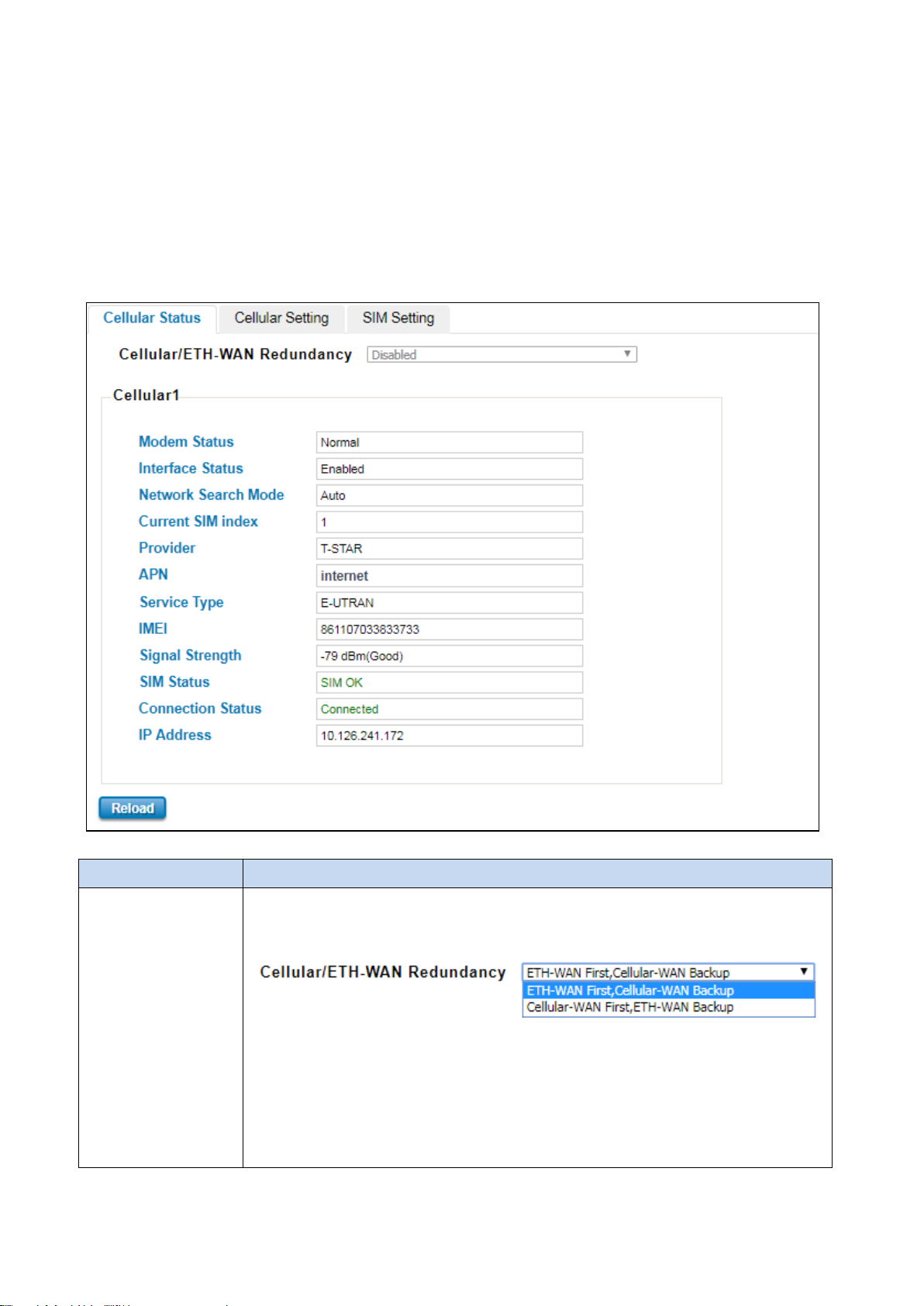
The figure below shows Cellular Status.
The description of the columns is as below:
TERMS DESCRIPTION
Cellular/ETH.WAN
Redundancy
Default: Disabled
User can choose the redundancy mode:
ETH-WAN First, Cellular-WAN Backup:
would be like prioritize the ETH-WAN connection; if the ETH-
problem then the Cellular-WAN would be the backup connection.
Cellular-WAN First, ETH-WAN Backup: by choosing this mode, the redunda
would be like prioritize the Cellular-WAN connection; if the Cellular-WAN connection has a
39
Page 40

is connected, the IP address will
problem then the ETH-WAN would be the backup connection.
Modem Status Display the modem status
Interface Status Display the Cellular interface status Enabled or Disabled
Network Search Mode Display the network search mode (Auto, 2G Only, 3G Only and LTE Only)
Current SIM Index Display the current in used SIM card (1 or 2)
Provider Display the ISP that user used.
APN Every ISP has a specific APN (Access Point Name) assigned to its cellular network. The
system can read this name from the SIM card.
Service Type The connected ISP will update the service type here. The possible types are GSM – 2G,
UMTS – 3G, GSM W/EGPRS, UTRAN W/HSDPA (download), UTRAN W/HSUPA(upload),
UTRAN W/HSDPA and HSUPA(download & upload), E-UTRAN - LTE , No Service(default
value)
IMEI Display the International Mobile Equipment Identity (IMEI)
Signal Strength The signal strength to the remote connected base station. If the signal strength shows low,
please change the device location or mounting the antenna in better location.
Below are the signal strength definitions in our system:
0 dBm (Default value while no connection)
-113 dBm or less (Low)
-111 dBm (Medium)
-109…-53 dBm (Good)
-51 dBm or greater (Excellent)
-Not known or not detectable
SIM Status Show the installed SIM Status.
SIM OK: The SIM card is okay to use.
SIM not inserted: The SIM card is not inserted.
SIM PIN Locked: The SIM card is locked due to PIN error. It may be caused by error
typing PIN password many times.
SIM PUK Locked: The SIM Card PUK is locked due to PIN error after user three times
input the wrong password. Contact the ISP to resolve the issue.
Connection Status Connection Status:
Connected: The cellular interface is connected.
Not Connected: The cellular interface is not connected.
IP Address The IP Address assigned by the ISP. While the cellular
display here.
40
Page 41
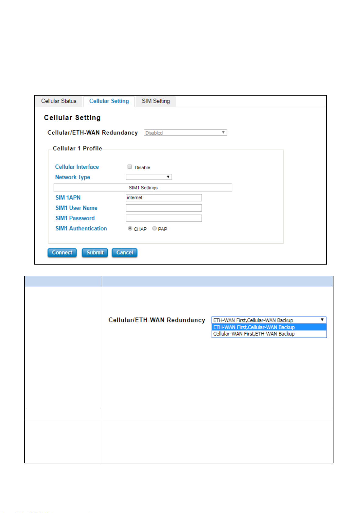
by choosing this mode, the redundancy mode
WAN connection has a
3.5.2 CELLULAR SETTING
This section displays the Cellular Setting configuration page and also in this configuration page user may activate the
redundant SIM function. In this section, user may configure the Cellular Interface, SIM Selection, Cellular Redundant,
Network Type, SIM1/2 APN, User Name, Password and the Authentication mode.
The figure below is the interface of WR312G:
The description of the columns is as below:
TERMS DESCRIPTION
Cellular/ETH.WAN
Redundancy
Cellular Interface To enable or disable the cellular interface. Click check to disable the function.
Network Type Set the Network Type, the option would be:
Default: Disabled
User can choose the redundancy mode:
ETH-WAN First, Cellular-WAN Backup:
would be like prioritize the ETH-WAN connection; if the ETH-
problem then the Cellular-WAN would be the backup connection.
Cellular-WAN First, ETH-WAN Backup: by choosing this mode, the redundancy mode
would be like prioritize the Cellular-WAN connection; if the Cellular-WAN connection has a
problem then the ETH-WAN would be the backup connection.
Auto: Search the network automatically
2G Only: only receive the 2G signal.
3G Only: only receive the 3G signal.
41
Page 42
LTE Only: only receive LTE/4G signal.
SIM1 APN Set the APN of the ISP.
SIM1 User Name Set the User Name
SIM1 Password Set the password.
SIM1 Authentication Choose CHAP or PAP mode for the authentication mode.
CHAP: Challenge Handshake Authentication Protocol, With CHAP, the authenticator (i.e.
the server) sends a randomly generated ``challenge'' string to the client, along with its
hostname.
PAP: Password Authentication Protocol, PAP works basically the same way as the normal
login procedure. The authenticates itself by sending a user name and a password to the
server
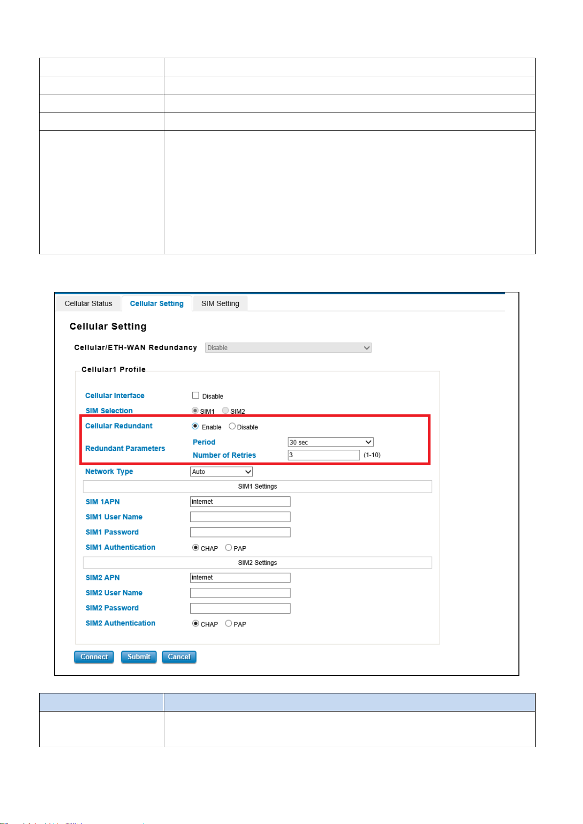
The figure below is the interface of C Series model and WR322GR that included the Dual SIM function and the SIM
Redundancy function.
The description of the columns is as below:
TERMS DESCRIPTION
Cellular/ETH.WAN
Redundancy
Default: Disabled
User can choose the redundancy mode:
42
Page 43

: by choosing this mode, the redundancy mode
WAN connection has a
: by choosing this mode, the redundancy mode
ETH-WAN First, Cellular-WAN Backup
would be like prioritize the ETH-WAN connection; if the ETH-
problem then the Cellular-WAN would be the backup connection.
Cellular-WAN First, ETH-WAN Backup
would be like prioritize the Cellular-WAN connection; if the Cellular-WAN connection has a
problem then the ETH-WAN would be the backup connection.
Cellular Interface To enable or disable the cellular interface. Click check to disable the function.
SIM Selection Default: SIM1
User can select the SIM card 1 or 2 that want to be activated or used.
Cellular Redundant Default: Disable
By enable this function, the SIM redundant function will be activated. The main function of
this feature is to have the backup SIM if the main SIM card is unable to use or have a
problem connection.
Redundant Parameters configuration appears after the user enables the function. If the
SIM card cannot be read after the redundant parameters are expired then it will directly
change to read the other SIM card.
Period: Set the period time to read the SIM card. The default value is 30 Seconds.
Number of Entries: Set the number of entries to give the remaining trial to read the SIM
card. The default value is 3.
Network Type Set the Network Type, the option would be:
Auto: Search the network automatically
2G Only: only receive the 2G signal.
3G Only: only receive the 3G signal.
LTE Only: only receive LTE/4G signal.
SIM1/2 APN Set the APN of the ISP.
SIM1/2 User Name Set the User Name
SIM1/2 Password Set the password.
SIM1/2 Authentication Choose CHAP or PAP mode for the authentication mode.
CHAP: Challenge Handshake Authentication Protocol, With CHAP, the authenticator (i.e.
the server) sends a randomly generated ``challenge'' string to the client, along with its
hostname.
PAP: Password Authentication Protocol, PAP works basically the same way as the normal
login procedure. The authenticates itself by sending a user name and a password to the
server
Click Submit to apply the configuration.
43
Page 44
The SIM card is locked due to PIN error. It may be caused
3.5.3 SIM SETTING
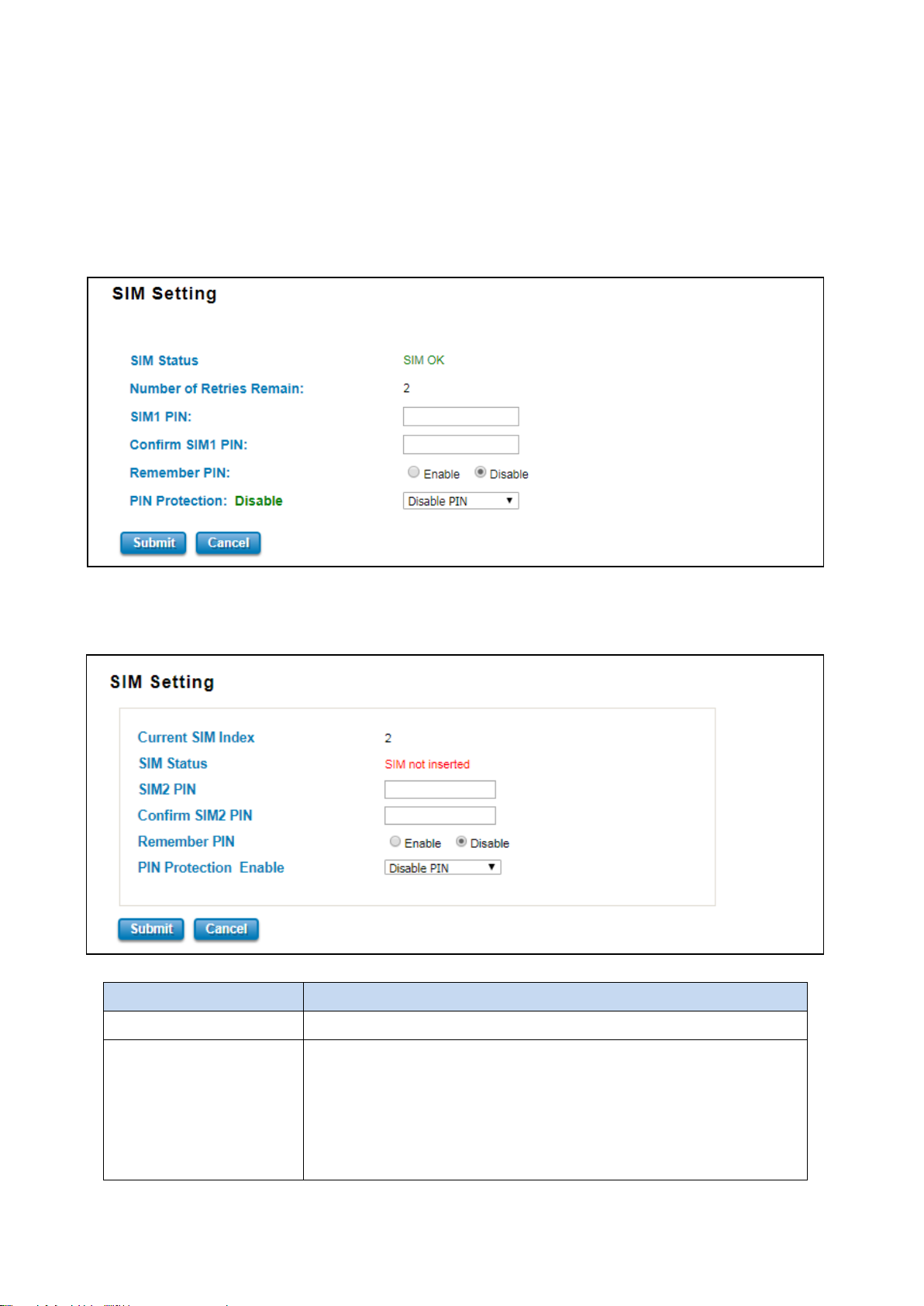
This section displays the SIM configuration such as SIM Status and SIM pin configuration. And in this section, user can
enable or disable the SIM protection function. Apply the PIN number to the SIM cards; and make sure user enters the
correct PIN number when activating the connection, after that the connection will start working. And also user can
change the new PIN settings.
The figure below belongs to WR312G:
The figure below belongs to C Series Model and WR322GR, it has the Current SIM Index section because the device is
supported with Dual SIM:
TERMS DESCRIPTION
Current SIM Index Display the current in used SIM Card slot (1 / 2)
SIM Status Show the installed SIM Status.
SIM OK: The SIM card is okay to use.
SIM not inserted: The SIM card is not inserted.
SIM PIN Locked:
by error typing PIN password many times.
44
Page 45

Contact the ISP to resolve the issue.
WARNING: SIM PUK Locked status will appear when the SIM Card PUK is
locked due to PIN error after user three times input the wrong password.
Number of Retries Remain Display the remaining chance to enter the PIN numbers.
SIM1/2 PIN Enter new SIM1/2 PIN numbers
Confirm SIM1/2 PIN Confirm the new SIM1/2 PIN numbers
Remember PIN Click enable to save the PIN numbers
PIN Protection Activate the PIN protection feature. Choose the mode from the drop list.
Disable PIN: Disable the PIN Protection feature
Enable PIN: Activate the PIN Protection feature
Change PIN: Change the PIN number, make sure user type the new PIN
Number first at the SIM1 PIN textbox.
Click Submit to apply the configuration.
45
Page 46
3.6 GPS
This GPS section has the function to show the current position of the device. The purpose of this feature is to display
the location of each device if there is device installation in large number. It could help the technician to track the
device location. WoMaster GPS feature is supported with the Global Navigation Satellite Systems use satellite
technology to provide insight on the geographic location of connected devices. GNSS is an inclusive term for the
category of global systems including GPS, GLONASS, BeiDou, and Galileo. Modern positioning and timing modules
have evolved to take advantage of multiple GNSS constellations at once. Combining multiple satellite systems
improves availability of signals, gives operators more access, and increases accuracy. Recent driving tests combining
GPS and GLONASS showed a noticeable improvement in both precision and performance when compared with
single system results. Whether user is navigating a position in a crowded city, a vast desert, or a dense forest,
utilizing multiple GNSS systems can help the device stays connected and centered.
3.6.1 GPS STATUS
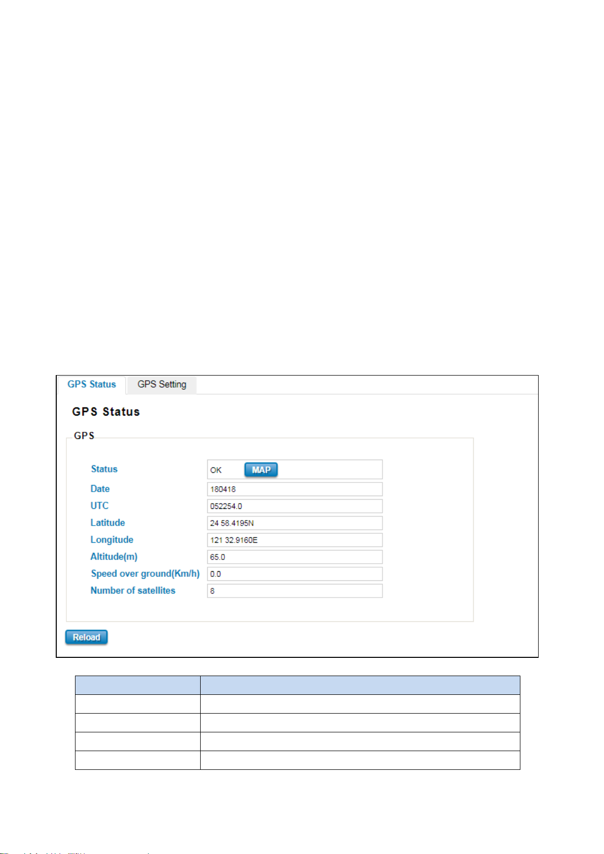
The first configuration page is GPS Status, where user can see all of the GPS information such as the GPS Status, Date,
UTC, Latitude, Longitude, Altitude (m), Speed over ground(Km/h) and the Number of satellites.
The description of the columns is as below:
TERMS DESCRIPTION
Status Display the GPS interface status OK or Disabled
Date Display the current date.
UTC Display the Coordinated Universal Time (UTC)
Latitude Display the latitude of the coordinate
46
Page 47
Longitude Display the longitude of the coordinate
Altitude(m) Display the altitude of the coordinate show the height or distance of an
object from sea level.
Speed over ground(Km/h) Display the speed over ground.
Number of satellites Display the number of satellites that help to fix the position (Minimum 4
satellites).
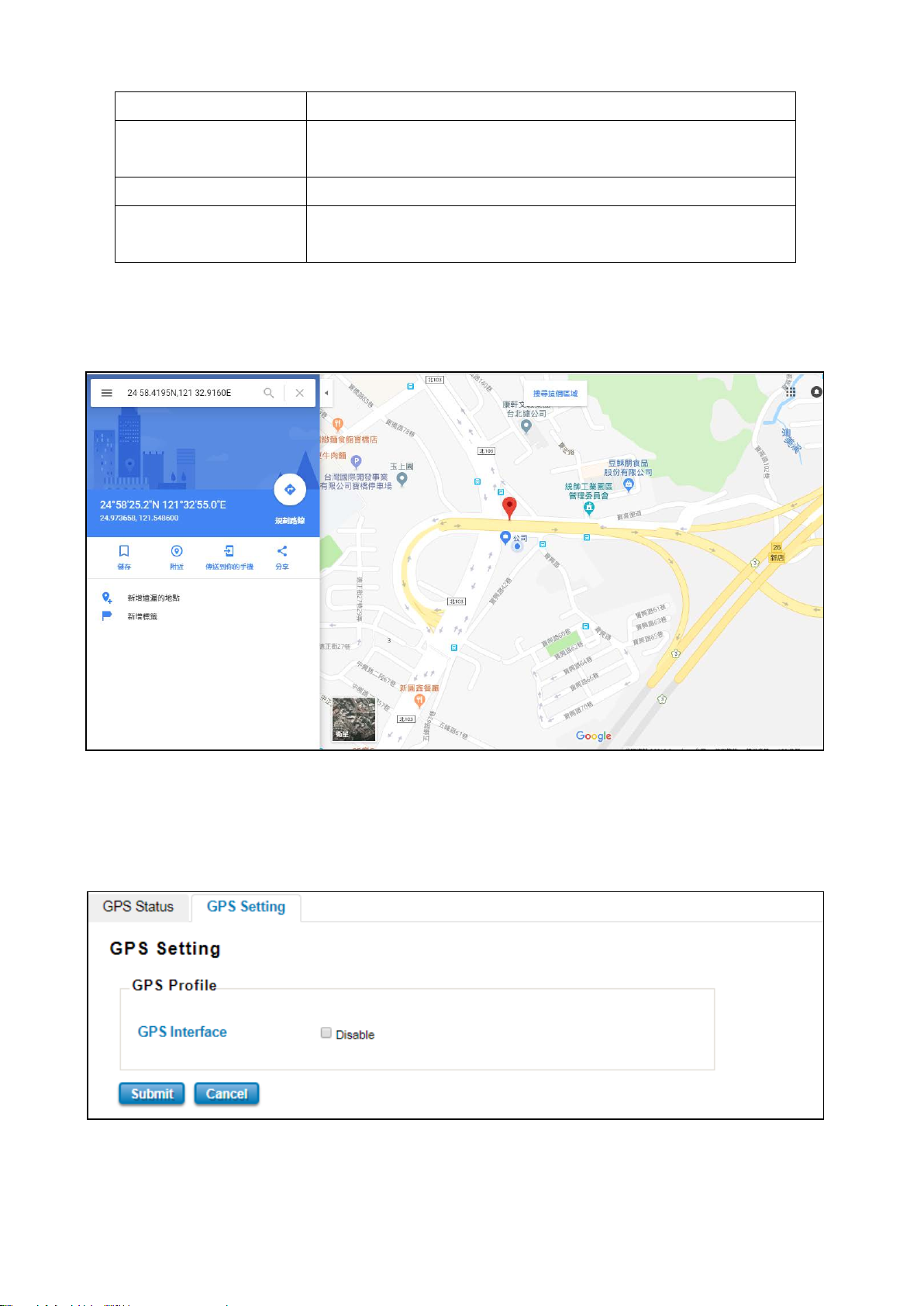
At the status section, a MAP button appears. Click this button to show the specific location of your device through
the Google Maps. After user clicks the button, the figure below will be appeared.
3.6.2 GPS SETTING
In this GPS Setting section, user can disable the GPS Interface by check the Disable. After user disables the function
the GPS Status will show disabled status for the GPS function.
47
Page 48
3.7 WIRELESS LAN
This Wireless LAN configuration pages only support the device that supported with Wi-Fi feature. This configuration
page allows users to configure the Wireless LAN configuration. Several settings are provided here such as the WLAN
Status, WLAN Setting, WLAN Security, Advanced and the Auto Offload.
3.7.1 WLAN STATUS
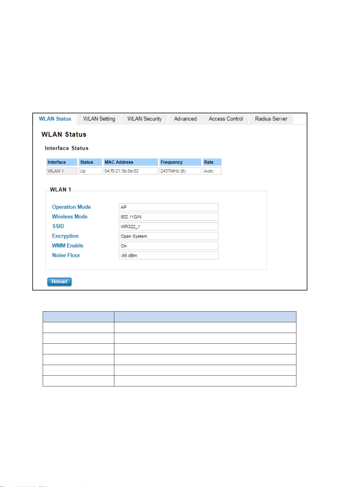
The figure below shows the WLAN status.
The description of the columns is as below:
TERMS DESCRIPTION
Operation Mode Display the current operating modes on the device
Wireless Mode Display the current wireless mode
SSID Display the primary name of the SSID
Encryption Display the encryption mode.
WMM Enable Display the status of the WMM support.
Noise Floor Display the background noise level.
3.7.2 WLAN SETTING
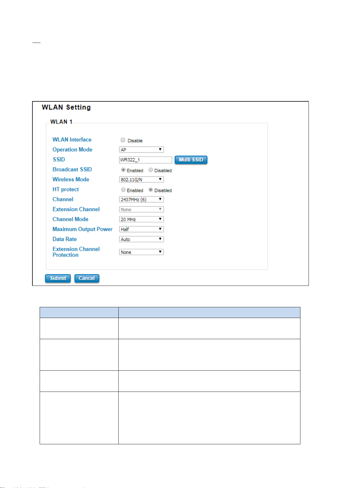
WLAN Setting page, on this page user may configure the parameters for Wireless LAN Interface includes change
wireless interface modes and all of the related parameters for each operation mode. And user can enable or disable
the WLAN interface.
48
Page 49
By enabling the broadcast SSID, it makes the AP can be accessed and
the network will be hidden in order to prevent any
AP
The Access Point mode, it establishes a wireless connection, receive from wireless clients and provide connection for
wireless client devices, the client can search and connect to several the access points. In AP mode interface, user can
configure the SSID name, Enable or Disable Broadcast SSID, select the Wireless mode, set the HT Protect to Enabled
or Disabled, set the Channel, Extension Channel, configures the Channel Mode, Maximum Output Power, Data Rate
and Extension Channel Protection.
The description of the columns is as below:
TERMS DESCRIPTION
WLAN Interface Check the box to disable the WLAN interface and stop all of the wireless
functions.
Operation Mode Default: AP
Select the Operation Mode for the router. (AP, Wireless Client, WDS-AP
and WDS-Client)
SSID Default: WR322_1
Input the primary name of the access point.
Broadcast SSID Default: Enabled.
searched by the clients, and for the security concern by disabling this
broadcast SSID,
malicious attack.
49
Page 50
igh Throughput protect to ensure HT
This option would be appeared when user select the Channel Mode to
ge for the frequency, it provides the
Lower Channel (2417MHz (2)) with the 40MHz center frequency is
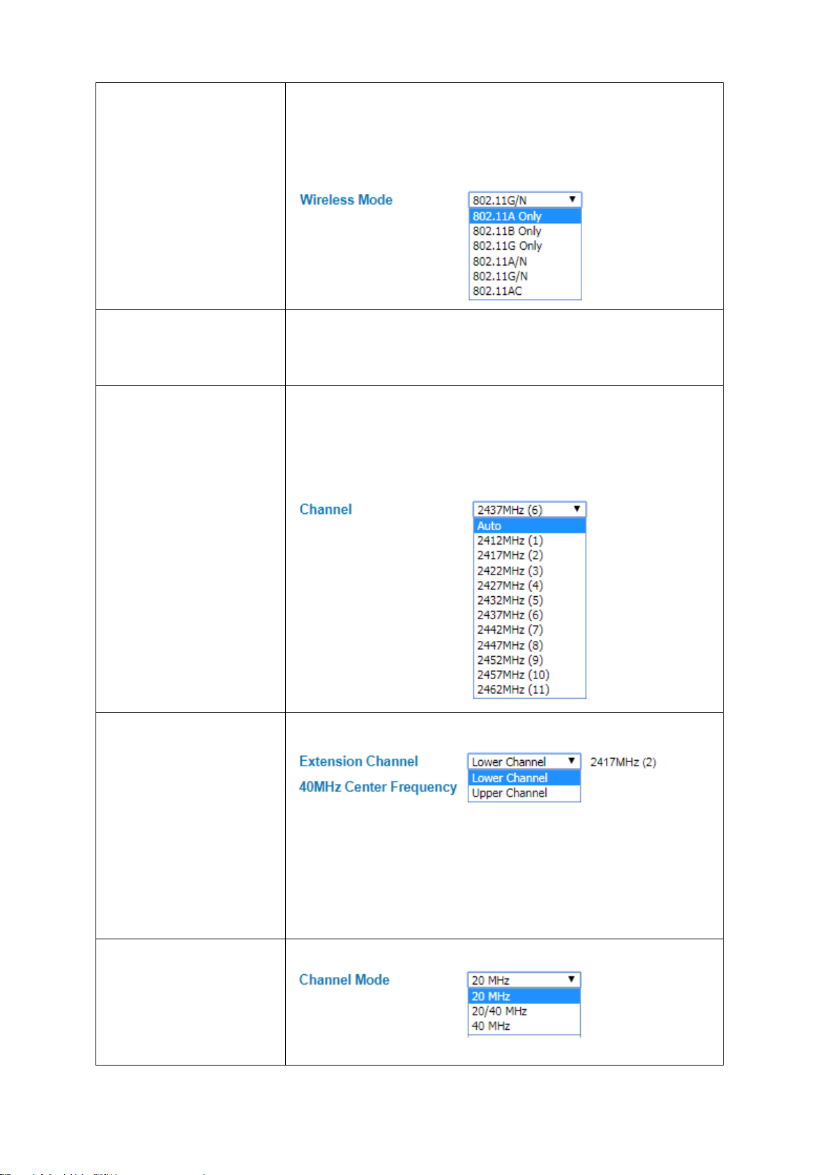
Wireless Mode Default: 802.11G/N
Select the specific wireless mode, different wireless mode has adifferent
configuration. For each wireless mode, it has the specific frequency and it
has different basic setting..
HT Protect Default: Disabled
Select Enabled to activate the H
transmission with MAC mechanism.
Channel Default: 2437MHz (6)
Select the proper channel, each country has different band user may
select the channel based on the situation. Or select auto to automatically
set the channel.
Extension Channel Default: Lower Channel 2417MHz (2)
20/40MHz or 40MHz. To put ran
2427MHz (4) and Upper Channel (2457MHz (10)) with the 40MHz center
frequency is 2447MHz (8).
Channel Mode Default: 20MHz
There are three channel modes, 20MHz, 20/40MHz and 40MHz. If user
50
Page 51
bigger data rate and received the 40MHz frequency. But basically, if the
Specify the transmission power. For the higher output power, it can cover
select 20MHz, the frequency that can be received maximum is 20MHz. For
20/40MHz it can receive both frequency, and for the 40MHz, it provides
transmission happened between the AP and the client, both AP and client
can have the negotiation phase about the frequency.
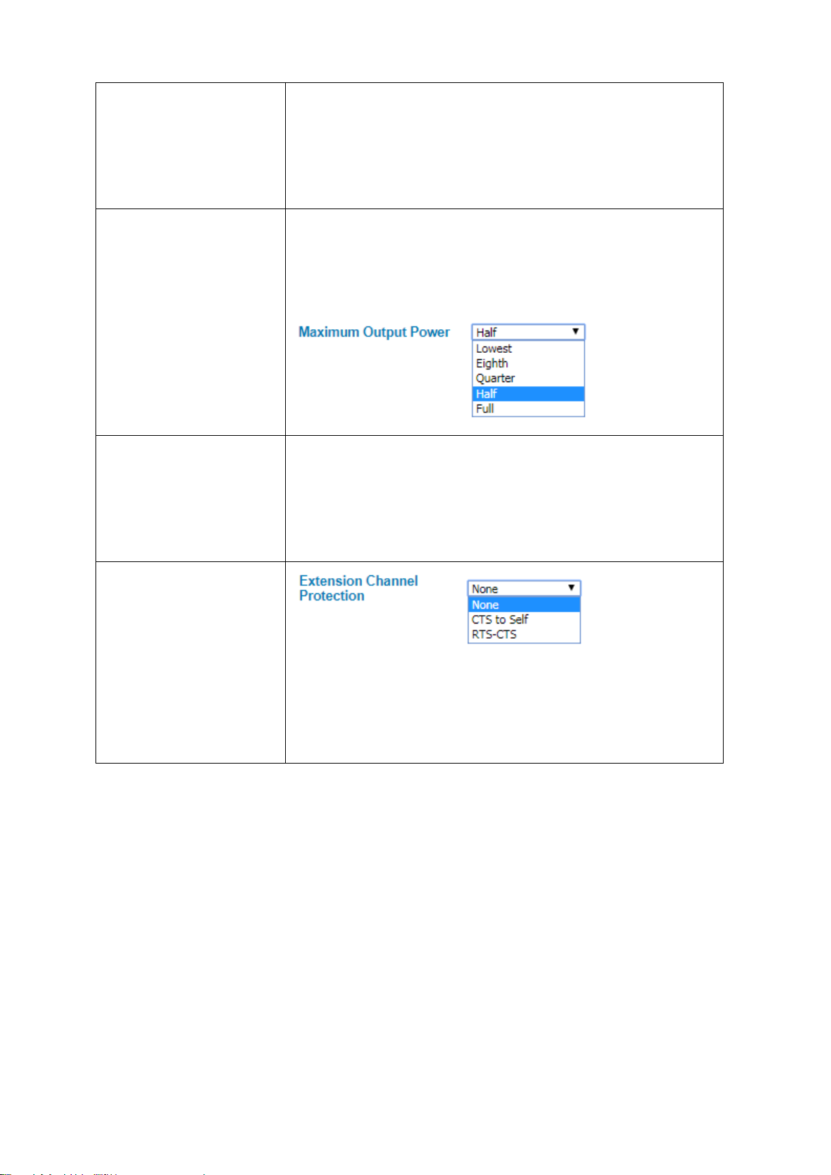
Maximum Output Power Default: Half
the signal widely and of course may need big power consumption. The Full
output power may need the antenna.
Data Rate Default: Auto
Extension Channel Protection
Click Submit to apply the configuration
Select the specific data rate in order to control the transmission rate. Auto
is preferred rate, the access point will automatically select the highest
available rate to transmit. User may select the low rate when there is no
great demand for transmission speed, for long distance transmission.
Select from the dropdown list option between CTS-Self or RTS-CTS to
avoid conflict with other wireless network and to improve the ability of
the device to catch all the wireless transmissions. By activating this
function it may decrease wireless network performance.
51
Page 52
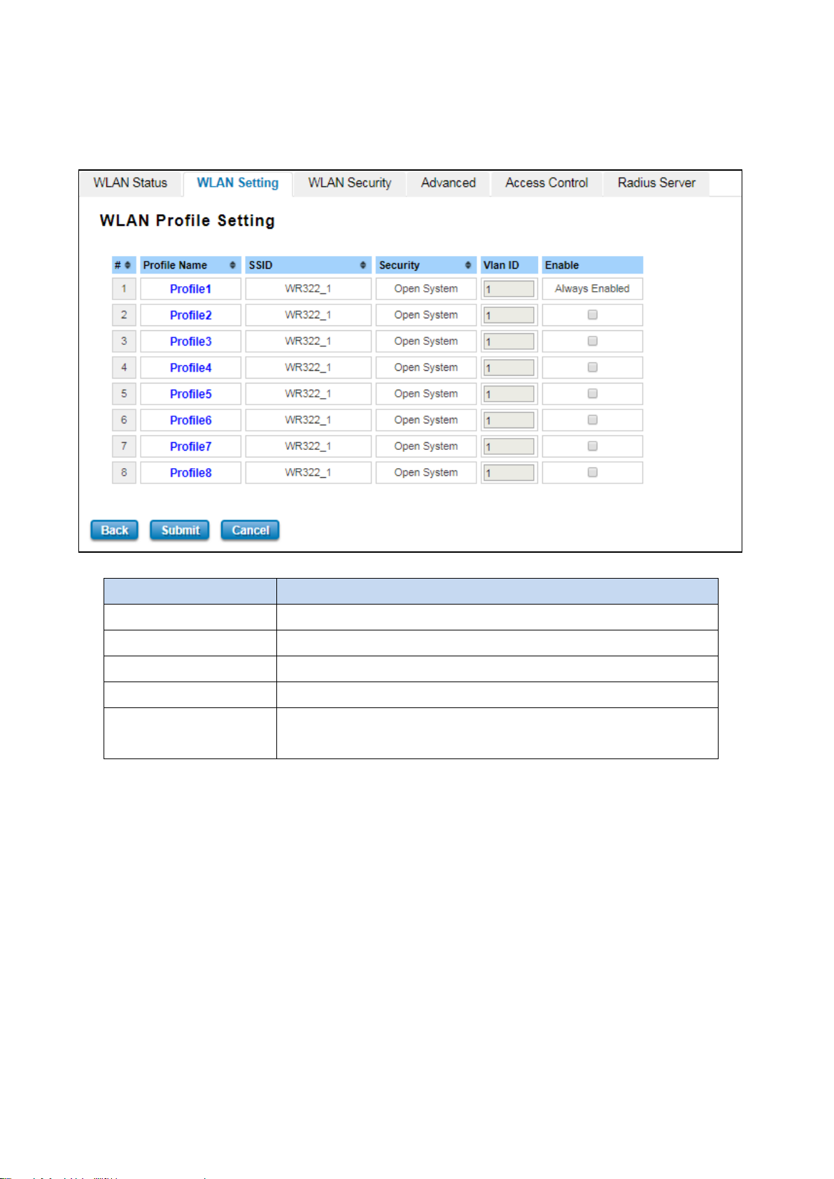
At the SSID section, there is a Multi SSID button appeared. This AP mode supports the multiple SSID or multiple
access point connections. So user may separate the connection into several access points and it is supported with 8
profiles for multiple SSID. Click the button then another form will appear, see the figure below.
The description of the column is as below:
TERMS DESCRIPTION
Profile Name Display the available WLAN Profile name
SSID Display the SSID Name.
Security Display the current security mode for the Wirelless network
VLAN ID Display the VLAN ID
Enable Check the box to enable the WLAN Profile. When user enabled the Profile,
user may configure the WLAN Setting by click the Profile name.
Click Submit to apply the configuration
52
Page 53
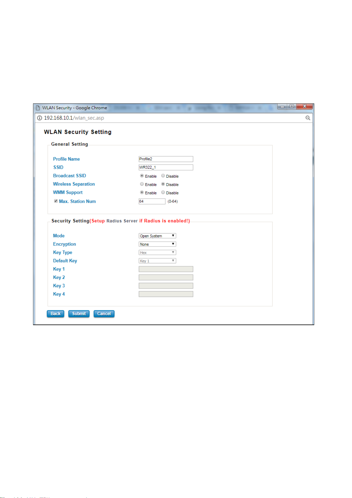
The Multi SSID section shows the configuration page where the Profile1 always enabled. In this section, user may
configure each Profile by check the box to enable the Profile and then click the profile name to open the
configuration page for specific Profile. The figure below is the pop-up WLAN Security configuration page for each
Profile. In this configuration page, user can configure the AP profile, divide the AP connection and set the security
setting by put the encryption mode and set the key or password to access the AP. Refers to the WLAN Security
Section for more description (3.7.3).
Click Submit to apply the configuration
53
Page 54
Wireless Client
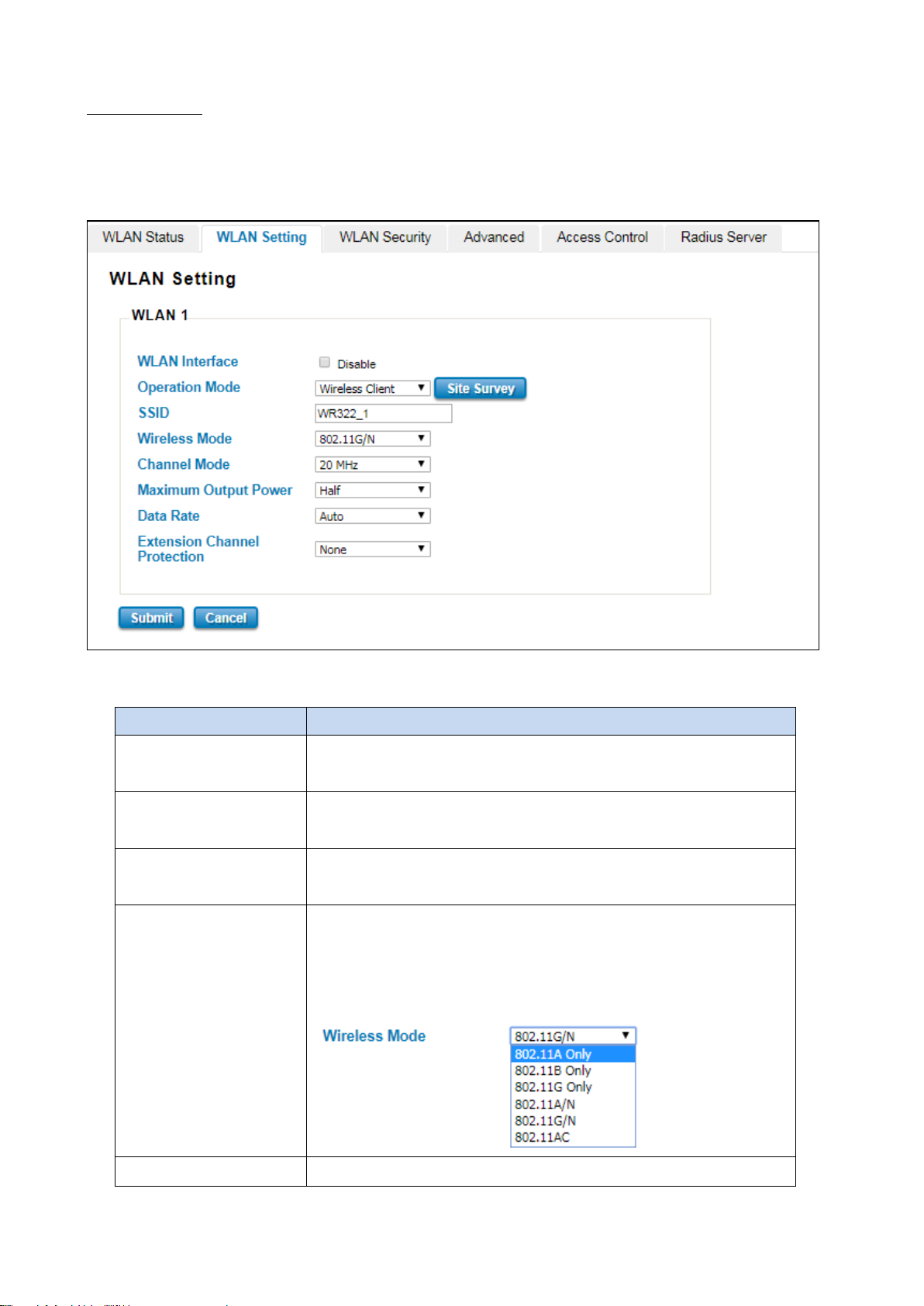
Wireless Client mode, in this mode the device is able to connect to the Access Point and join the wireless network
around the device that opens the connection. User can find the best connection for the AP by click the Site Survey
and the AP list will appear.
The description of the columns is as below:
TERMS DESCRIPTION
WLAN Interface Check the box to disable the WLAN interface and stop all of the wireless
functions.
Operation Mode Select the Operation Mode for the router. (AP, Wireless Client, WDS-AP
and WDS-Client)
SSID Default: WR322_1
Input the primary name of the access point.
Wireless Mode Default: 802.11G/N
Select the specific wireless mode, different wireless mode has a different
configuration. For each wireless mode, it has a specific frequency and it
has different basic setting..
Channel Default: 2437MHz (6)
54
Page 55

Extension Channel
Select the proper channel, each country has different band user may select
the channel based on the situation. Or select auto to automatically set the
channel.
Maximum Output Power Default: Half
Specify the transmission power. For the higher output power, it can cover
the signal widely and of course may need big power consumption. The Full
output power may need the antenna.
Data Rate Default: Auto
Select the specific data rate in order to control the transmission rate. Auto
is preferred rate; the access point will automatically select the highest
available rate to transmit. User may select lower rate when there is no
great demand for transmission speed, for long distance transmission.
Protection
Select from the drop down list option between CTS-Self or RTS-CTS to
avoid conflict with other wireless network and to improve the ability of the
Click Submit to apply the configuration
device to catch all the wireless transmissions. By activating this function, it
may decrease wireless network performance.
55
Page 56
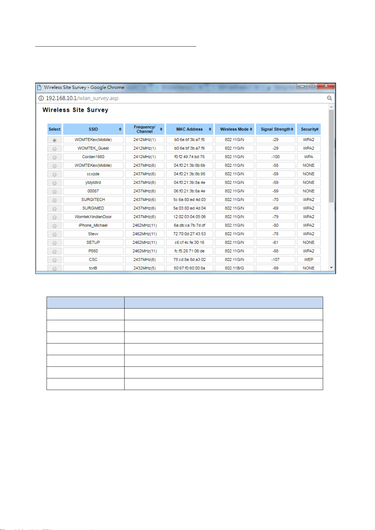
Wireless Site Survey (Wireless Client & WDS-Client)
Click the Site Survey button to open the Wireless Site Survey page. On this page user may choose the Access Point
that appeared on the list. After selects the specific AP, then click Selected to apply the choice. Click Scan to refresh
the list.
The description of the columns is as below:
TERMS DESCRIPTION
Select Select the SSID.
SSID Display the detected SSID’s name
Frequency/Channel Display the current frequency of the AP.
MAC Address Display the listed AP MAC Address.
Wireless Mode Display the Wireless mode.
Signal Strength Display the signal strength
Security The security mode of the Access Point.
Click Selected to connect to the specific SSID.
56
Page 57
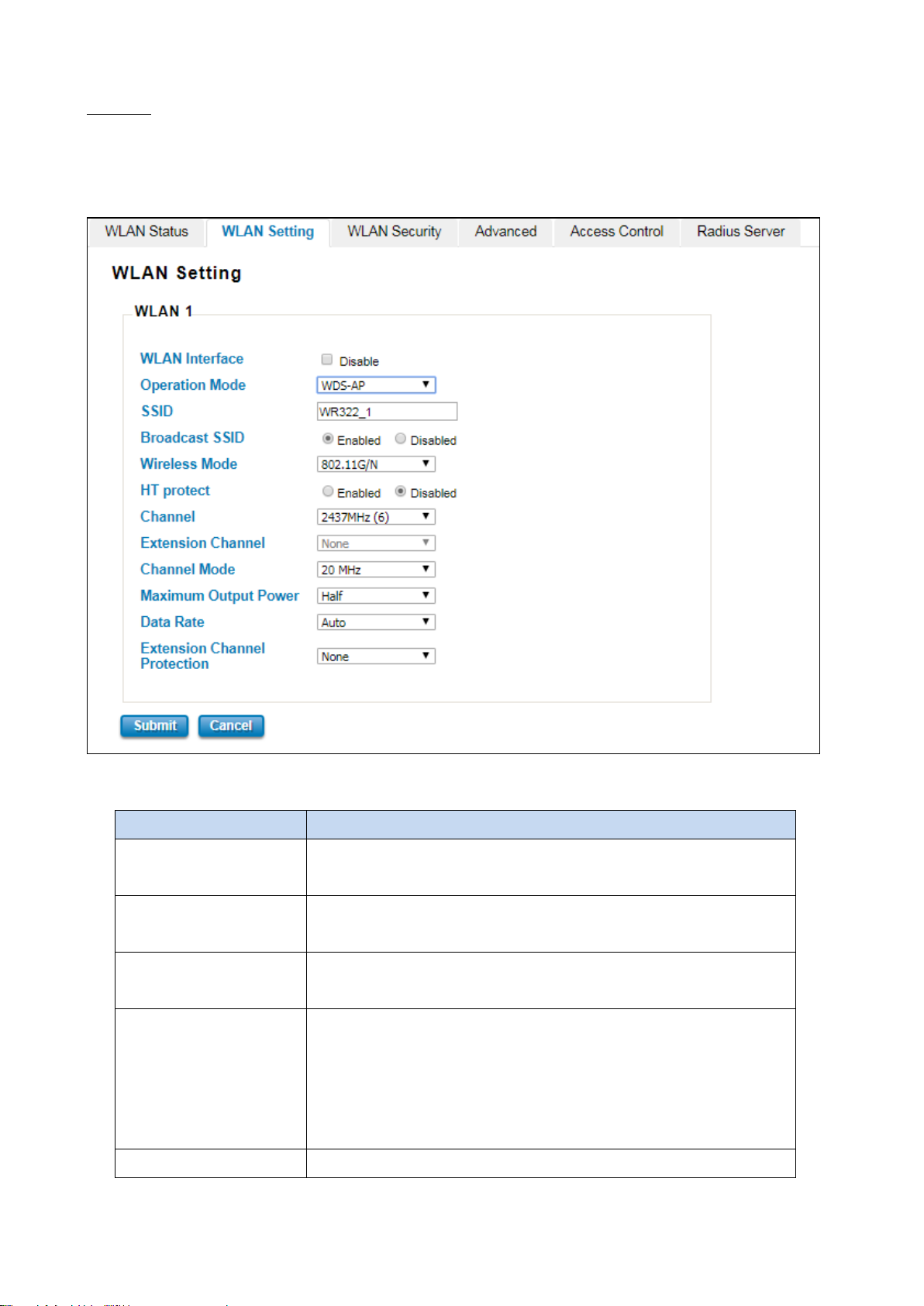
By enabling the broadcast SSID, it makes the AP can be accessed and
the network will be hidden in order to prevent any
WDS-AP
The WDS-AP mode usually implements the Point to Point (P2P) connection, so the access point should be WDS-AP
and the wireless client should be WDS-Client. So in this case, the AP just can share the connection to the specific
wireless client that has its MAC Address. But WDS-AP can be a repeater to provide network access to general clients.
The description of the columns is as below:
TERMS DESCRIPTION
WLAN Interface Check the box to disable the WLAN interface and stop all of the wireless
function.
Operation Mode Select the Operation Mode for the router. (AP, Wireless Client, WDS-AP
and WDS-Client)
SSID Default: WR322_1
Input the primary name of the access point.
Broadcast SSID Default: Enabled.
searched by the clients, and for the security concern by disabling this
broadcaset SSID,
malicious attack.
Wireless Mode Default: 802.11G/N
57
Page 58
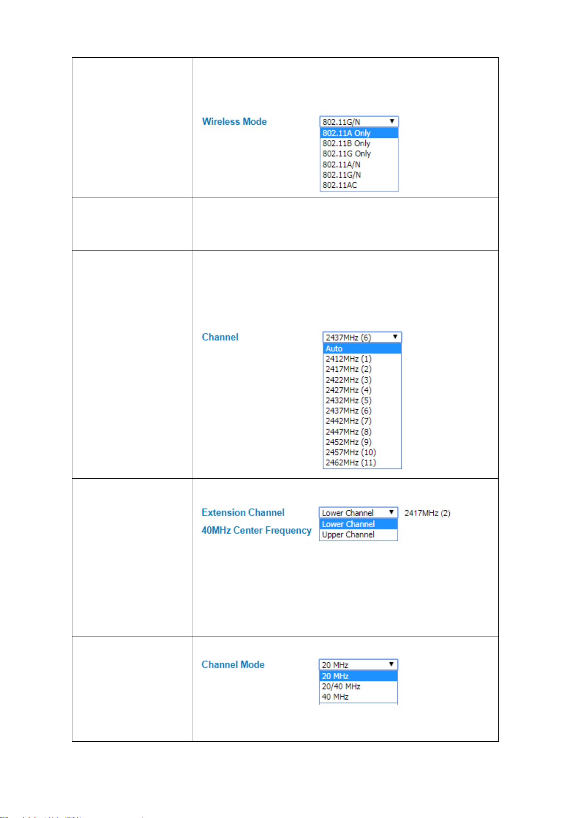
igh Throughput protect to ensure HT
This option would be appeared when user select the Channel Mode to
equency, it provides the
Lower Channel (2417MHz (2)) with the 40MHz center frequency is
Select the specific wireless mode, different wireless mode has different
configuration. For each wireless mode, it has specific frequency and it has
different basic setting.
HT Protect Default: Disabled
Select Enabled to activate the H
transmission with MAC mechanism.
Channel Default: 2437MHz (6)
Select the proper channel, each country has different band user may select
the channel based on the situation. Or select auto to automatically set the
channel.
Extension Channel Default: Lower Channel 2417MHz (2)
20/40MHz or 40MHz. To put range for the fr
2427MHz (4) and Upper Channel (2457MHz (10)) with the 40MHz center
frequency is 2447MHz (8).
Channel Mode Default: 20MHz
There are three channel modes, 20MHz, 20/40MHz and 40MHz. If user
select 20MHz, the frequency that can be received maximum is 20MHz. For
58
Page 59
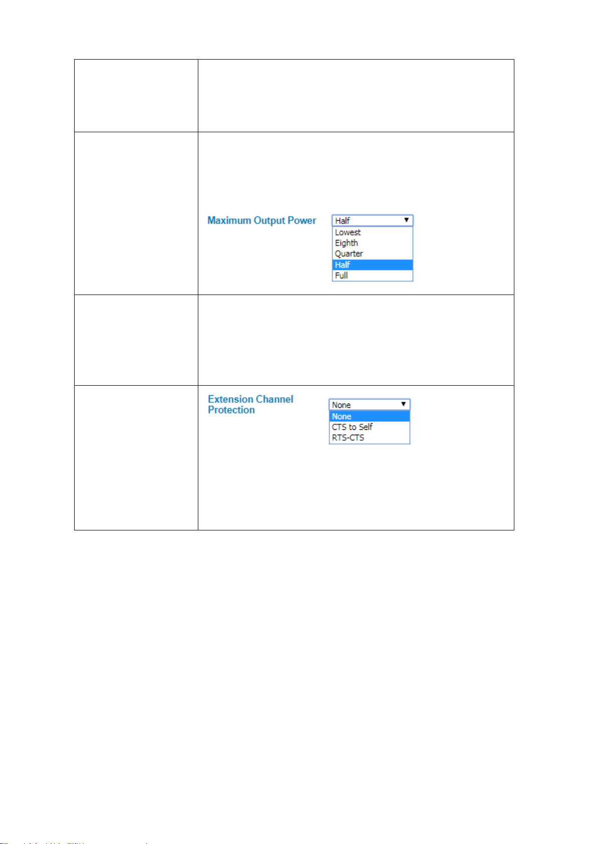
bigger data rate and received the 40MHz frequency. But basically, if the
Extension Channel
20/40MHz it can receive both frequency, and for the 40MHz, it provides
transmission happened between the AP and the client, both AP and client
can have the negotiation phase about the frequency.
Maximum Output Power Default: Half
Specify the transmission power. For the higher output power, it can cover
the signal widely and of course may need big power consumption. The Full
output power may need the antenna.
Data Rate Default: Auto
Select the specific data rate in order to control the transmission rate. Auto
is preferred rate; the access point will automatically select the highest
available rate to transmit. User may select the low rate when there is no
great demand for transmission speed, for long distance transmission.
Protection
Select from the dropdown list option between CTS-Self or RTS-CTS to avoid
conflict with other wireless network and to improve the ability of the
device to catch all the wireless transmissions. By activating this function it
may decrease wireless network performance.
Click Submit to apply the configuration
59
Page 60
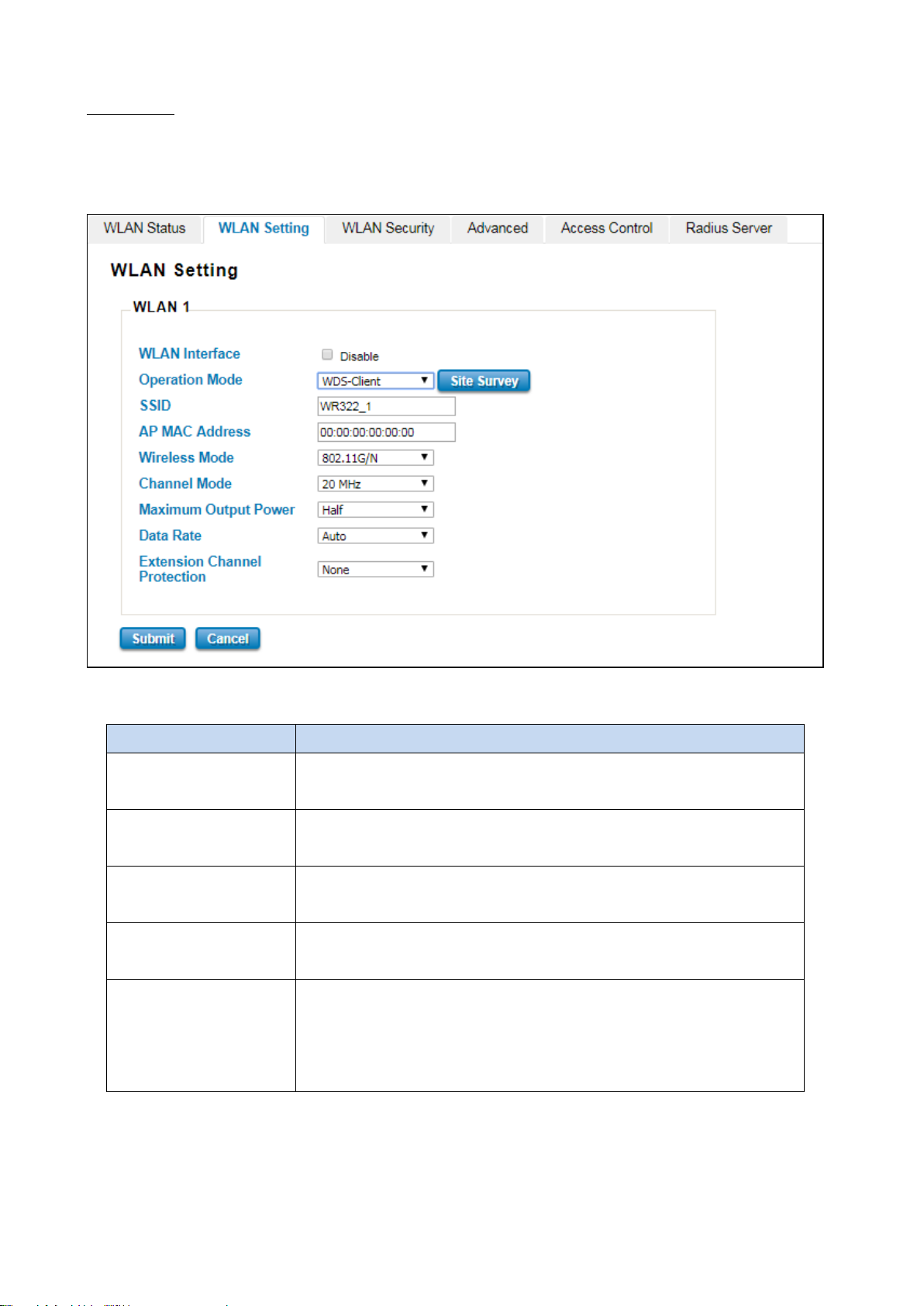
WDS-Client
In WDS-Client mode, user must specify the specific WDS-AP’s SSID and MAC address. So WDS-Client just do the
transmission to the WDS-AP only. In this mode, please make sure that the configuration should be the same as the
WDS-AP as well.
The description of the columns is as below:
TERMS DESCRIPTION
WLAN Interface Check the box to disable the WLAN interface and stop all of the wireless
functions.
Operation Mode Select the Operation Mode for the router. (AP, Wireless Client, WDS-AP and
WDS-Client)
SSID Default: WR322_1
Input the primary name of the access point.
AP MAC Address Default: 00:00:00:00:00:00
Set the specific AP MAC Address of the WDS-AP.
Wireless Mode Default: 802.11G/N
Select the specific wireless mode, different wireless mode has a different
configuration. For each wireless mode, it has a specific frequency and it has
different basic setting.
60
Page 61
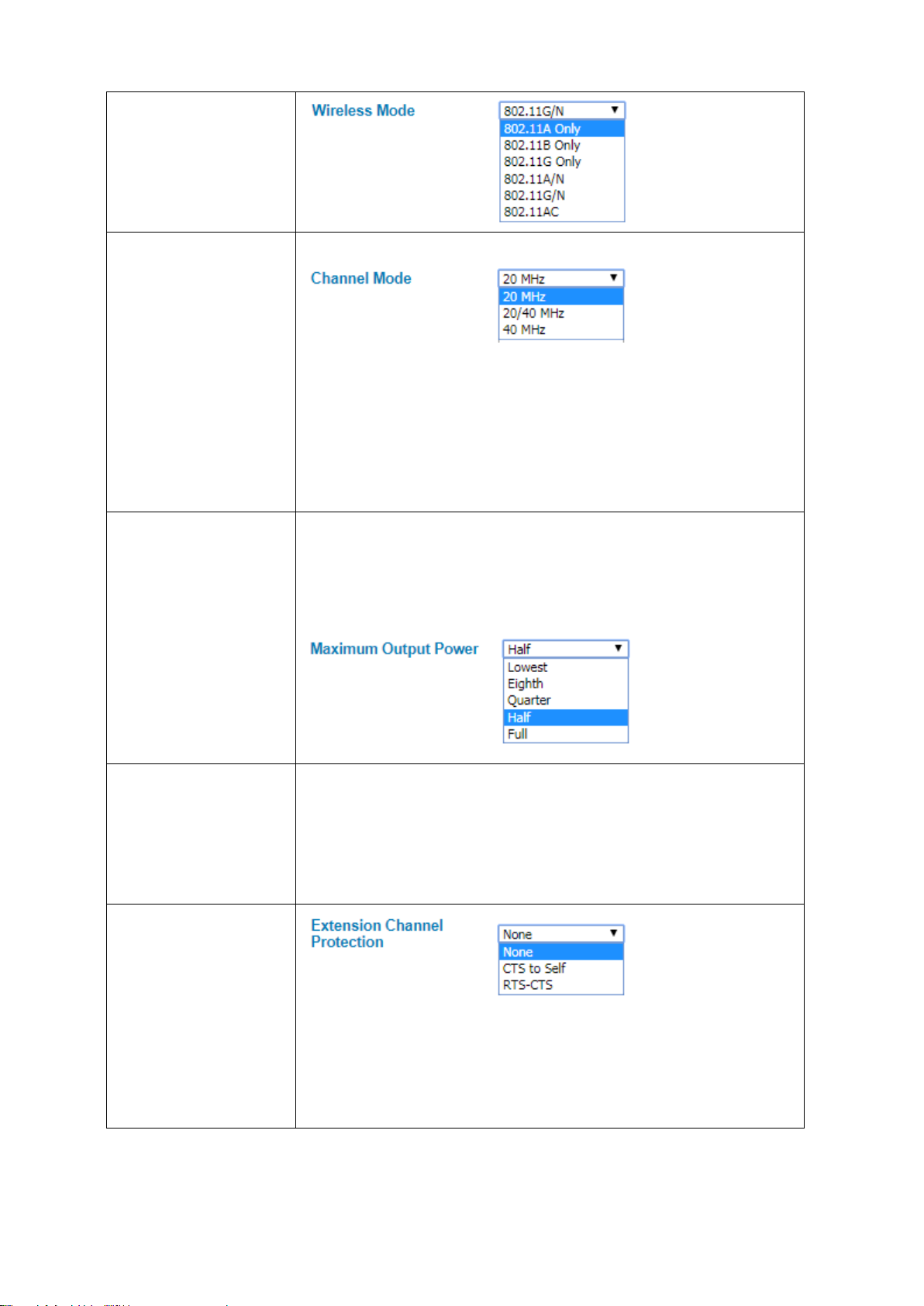
MHz it can receive both frequency, and for the 40MHz, it provides
bigger data rate and received the 40MHz frequency. But basically, if the
transmission happened between the AP and the client, both AP and client can
Channel Mode Default: 20MHz
There are three channel modes, 20MHz, 20/40MHz and 40MHz. If user select
20MHz, the frequency that can be received maximum is 20MHz. For
20/40
have the negotiation phase about the frequency.
Maximum Output Power Default: Half
Specify the transmission power. For the higher output power, it can cover the
signal widely and of course may need big power consumption. The Full output
power may need the antenna.
Data Rate Default: Auto
Select the specific data rate in order to control the transmission rate. Auto is
preferred rate, the access point will automatically select the highest available
rate to transmit. User may select the low rate when there is no great demand
for transmission speed, for long distance transmission.
Extension Channel
Protection
Select from the dropdown list option between CTS-Self or RTS-CTS to avoid
conflict with other wireless network and to improve the ability of the device
to catch all the wireless transmissions. By activate this function it may
decrease wireless network performance.
61
Page 62
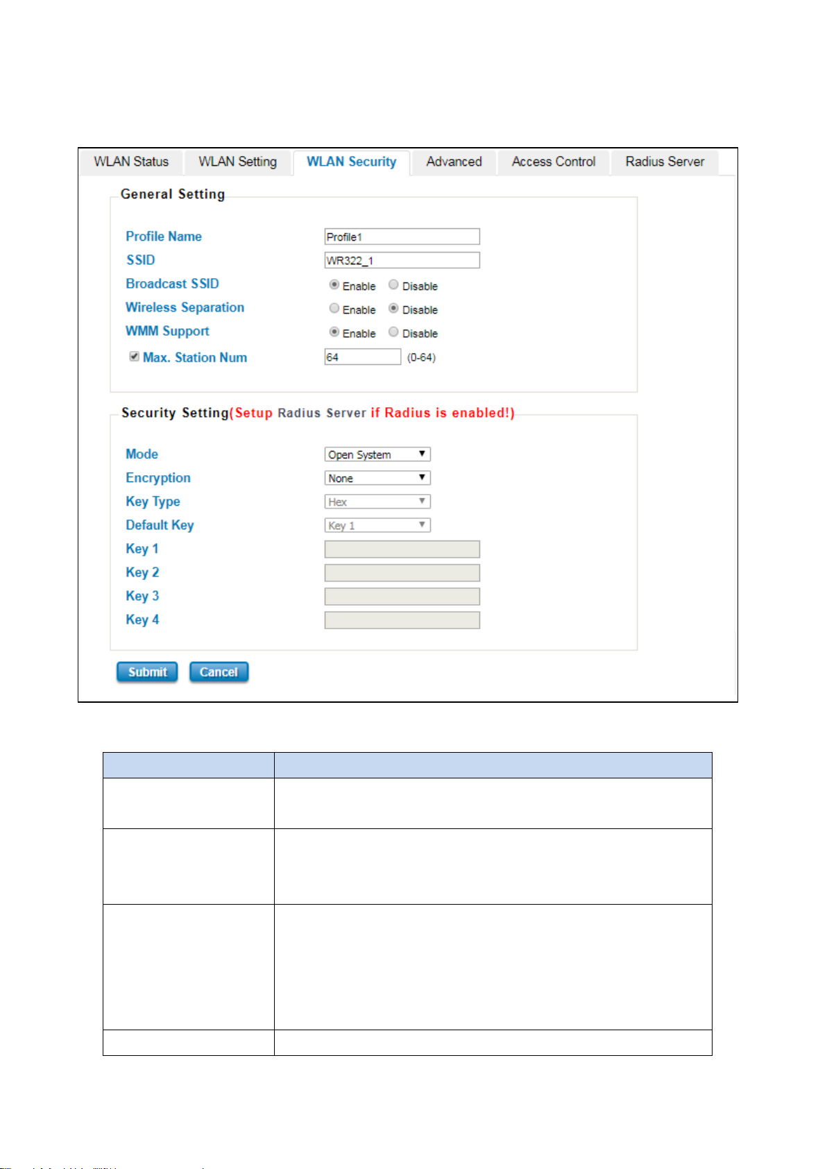
the network will be hidden in order to prevent any
3.7.3 WLAN SECURITY
On this configuration page, user can configure the WLAN Security feature.
The description of the columns is as below:
TERMS DESCRIPTION
Profile Name Default: Profile1
Set the profile name for the Access Point.
SSID Default: WR322_1
Set the Service Set Identifier name, this ID can be recognized by the Client
when the WLAN connection is established.
Broadcast SSID Default: Enabled.
By enabling the broadcast SSID, it makes the AP can be accessed and
searched by the clients, and for the security concern by disabling this
broadcast SSID,
malicious attack.
Wireless Separation Default: Disable
62
Page 63
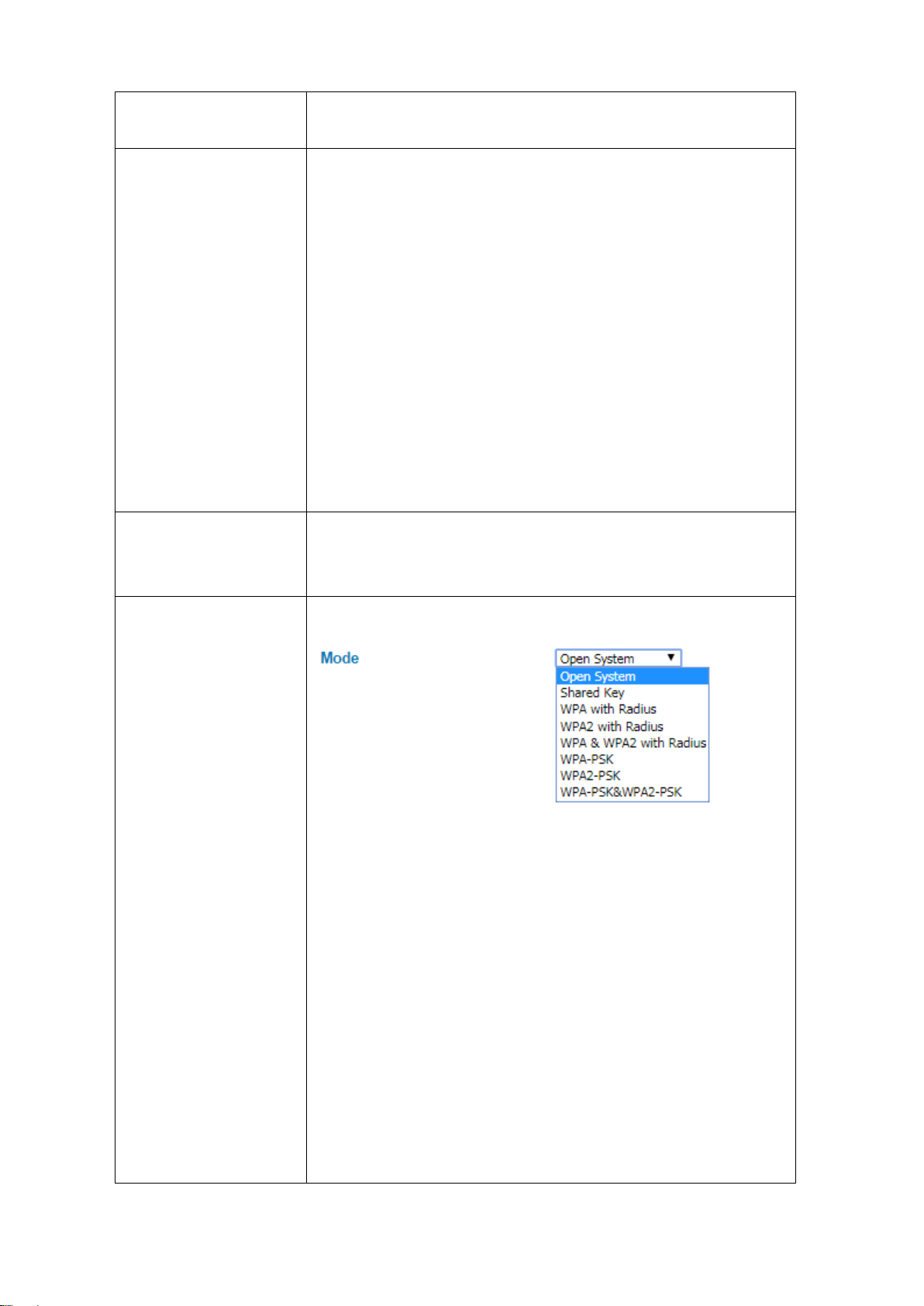
A subset of the WLAN specification that enhances quality of service (QoS)
: Giving voice packets the highest priority enables concurrent
any device to join the network without security
: A simplified WPA mode that no need to specify the
Under the AP mode, enable it to prevent one wireless device from directly
communicating with another on the same AP
WMM Support Default: Enable
on a network by prioritizing data packets onto four categories.
Ranging from highest priority to lowest, these categories are:
Voice
Voice over IP (VoIP) calls with minimal latency and the highest quality
possible.
Video: By placing video packets in the second tier, WMM prioritizes
it over all other data traffic.
Best effort: Best effort data packets consist of those originating from
legacy devices or from applications or devices that lack QoS standards.
Background: Background priority encompasses file downloads, print
jobs and other traffic that does not suffer from increased latency.
Max Station Number Default: 64 (0-64)
Set the maximum number of station that can communicate with the
access point.
Mode Default: Open System
Open System: It allows
checks.
Shared Key: Data encryption and key are required for the authentication.
WPA with RADIUS: With warrant (username, password and etc.) offered
by user, this kind of authentication can be realized with specific RADIUS
server.
WPA2 with RADIUS: A new version of WPA, only clients that supported
with WPA2 can apply this security function. The AES encryption RADIUS
server is required.
WPA & WPA2 with RADIUS: AES & TKIP encryption and RADIUS server is
required.
WPA-PSK
authentication server. It can be called as WPA Pre-Shared Key, a user just
63
Page 64

needs to enter a key in each WLAN node. The data encryption can only
TKIP.
WPA2-PSK: A new version of WPA, only clients that supported with WPA2
can apply this security function. The data encryption can only be AES and
WPA Pre-Share Key is required.
WPA-PSK&WPA2-PSK: The data encryption will be AES & TKIP and WPA
Pre-Share Key is required.
Encryption Configure the data encryption mode.
None: Available only when the authentication type is an open system.
64 bits WEP: It is made up of 10 hexadecimal numbers.
128 bits WEP: It is made up of 26 hexadecimal numbers.
TKIP: Temporal Key Integrity Protocol, which is a kind of dynamic
encryption, is co-used with WPA-PSK.
AES: Advanced Encryption Standard, it is usually co-used with
WPA2-PSK.
Key Type Default: Hex
WEP can be configured with a 64-bit or 128-bit Shared Key (hexadecimal or
ASCII). As defined, hexadecimal number is represented by 0-9, A-F or a-f;
ASCII is represented by 0-9, A-F, a -f or punctuation. Each one consists of
two-digit hexadecimal.
Default Key Default: Key 1
Set the specific default key.
Key 1~4 Enter the specific encryption key.
3.7.4 ADVANCED
The page allows the advanced user to configure advanced wireless setting with more experience about the WLAN. If
user doesn’t have any qualified knowledge about WLAN, we suggest not to change the default setting except user
know what is the effect when the setting is changed. The wrong configuration may impact the performance of
wireless network.
64
Page 65
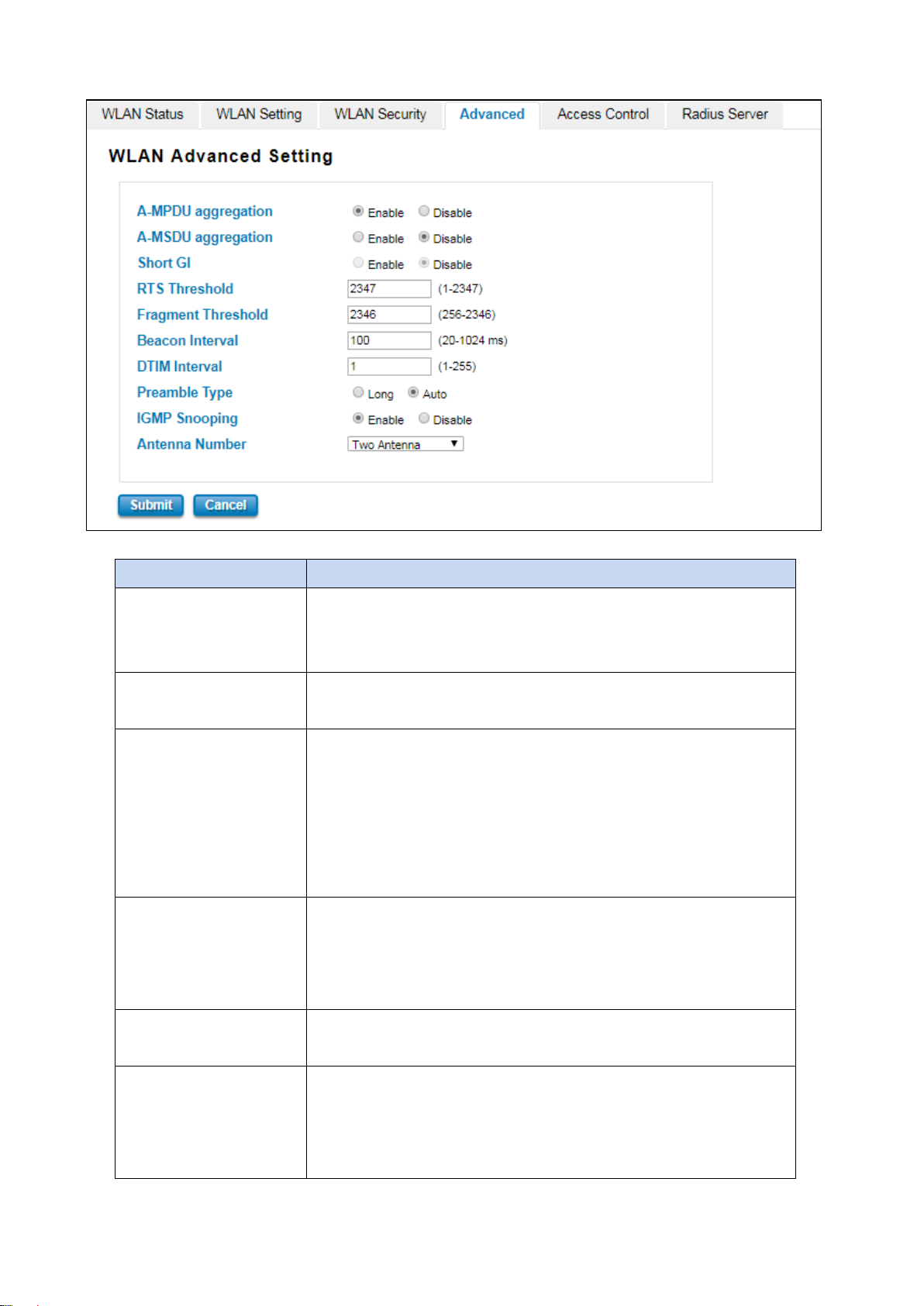
The description of the columns is as below:
TERMS DESCRIPTION
A-MPDU/A-MSDU
aggregation
Short GI Enable this function to obtain better data rate. (careful with compatibility
RTS Threshold Default: 2347 (1-2347)
Fragment Threshold Default: 2346 (256-2436)
For the AP mode, by enabling this function the data rate of the AP could
be enhanced greatly, Do not enable this function if the wireless clients
don’t support A-MPDU/A-MSDU aggregation.
issue)
Basically, it is about the transmission process between the AP and the end
station. When the AP sends Request to Send frames to station and it will
do the negotiation process about sending the data frame. When the
station receives an RTS frame, the station will respond with send back
Clear to Send frame to confirm the right to start transmission.
Specify the maximum size in byte for a packet before data is fragmented
into multiple packets. Setting it too low may result in poor network
performance.
Beacon Interval Default: 100ms (20-1024 ms)
Specify the interval to broadcast packets.
DTIM Interval Default: 1 (1-255)
Delivery Traffic Indication Message interval is an additional message added
after the beacon interval broadcast by access point. It is for enhancing the
wireless transmission efficiency. The more intervals we added, the more
65
Page 66

devices awake indefinitely so they never go into sleep mode
preamble type divided into two, long and short. Short is for shorter data
y enabling IGMP Snooping allows the ports to detect IGMP queries,
ty to prune multicast traffic so that it travels
power that we need. By setting a low value of DTIM, user can effectively
keep the
when idling.
Preamble Type Default: Long
Preamble Type setting means that it adds some additional data header
strings to help check the Wi-Fi data transmission errors. Basically,
strings that adds less data to transmit the error redundancy check which
means that it is much faster. Long Preamble Type uses longer data strings
which allow for better error checking capability. Auto Preamble Type the
device can set the Preamble Type Automatically according to the need,
which is can be long or can be short.
IGMP Snooping Default: Enable
B
report packets, and manage multicast traffic through the AP. IGMP
Snooping provides the abili
only to those end destinations that require that traffic.
Antenna Number Default: Two Antenna
The Antenna Number setting allows user to choose the antenna that used
in the wireless connection. Basically, the default setting is set to Two
antennas, because the device itself provide two antenna sockets. User can
configure One Antenna or Two Antenna. Please refer to the Antenna
Placement table to connect the antenna correctly.
3.7.5 ACCESS CONTROL (AP MODE)
This page allows user configure the Wireless Access Control list. User can add the rule to Allow list or Deny list for the
security concern to access WLAN.
66
Page 67
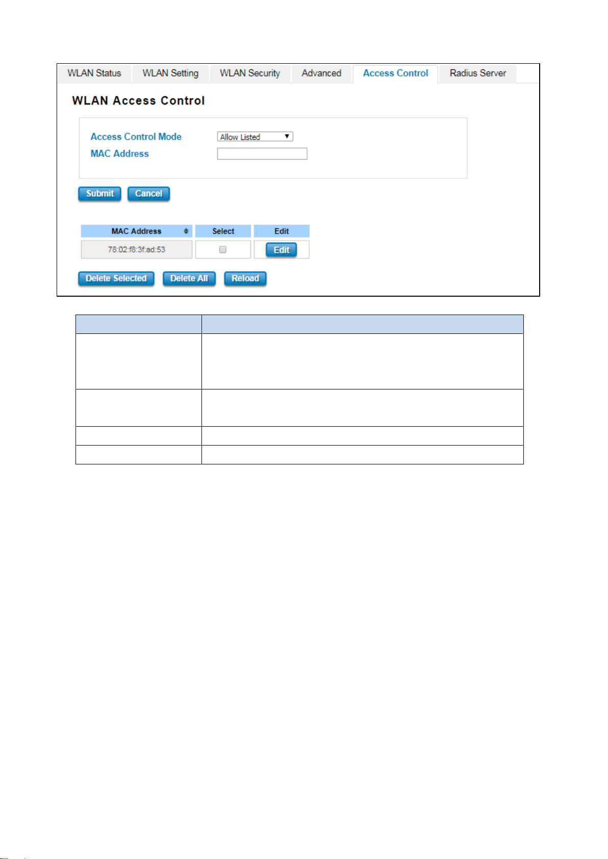
The description of the columns is as below:
TERMS DESCRIPTION
Access Control Mode Default: Disable
Allow List – Allow the specific MAC Address to access the WLAN
Deny List – Deny the specific MAC Address to access the WLAN
MAC Address Display the specific MAC Address that allowed or denied to access the
WLAN.
Select Select the MAC Address list.
Edit Click to edit the Access Control Mode for the specific MAC Address
67
Page 68
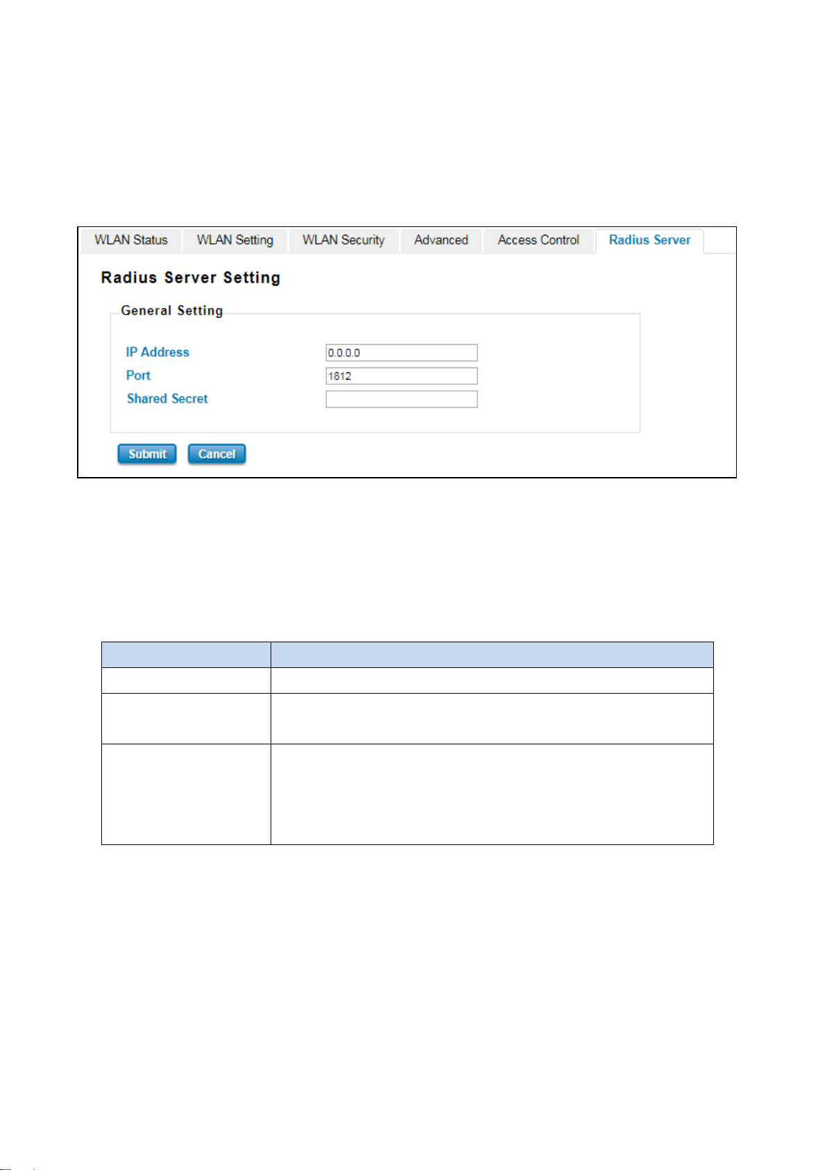
that the
3.7.6 RADIUS SERVER (AP MODE)
The Remote Authentication Dial In User Service (RADIUS) mechanism is a centralized “AAA” (Authentication,
Authorization, and Accounting) system for connecting to network services. The fundamental purpose of RADIUS is to
provide an efficient and secure mechanism for user account management. The RADIUS server system allows you to
access the router through secure networks against unauthorized access.
How to set up a RADIUS server:
a. Enter the IP address of the RADIUS server in Server IP Address
b. Enter the Shared Secret of the RADIUS server
c. Enter the Server port if necessary, by default RADIUS server listens to port 1812
d. Click Submit
The description of the RADIUS Authentication interface is as below:
TERMS DESCRIPTION
IP Address Radius Server IP Address
Server Port Set communication port on an external RADIUS server as the
authentication database. The default value is 1812
Shared Key Shared key is used to verify that RADIUS messages, with the exception of
the Access-Request message, are sent by a RADIUS-enabled device that is
configured with the same shared key. Shared key also verifies
RADIUS message has not been modified in transit (message integrity).
68
Page 69
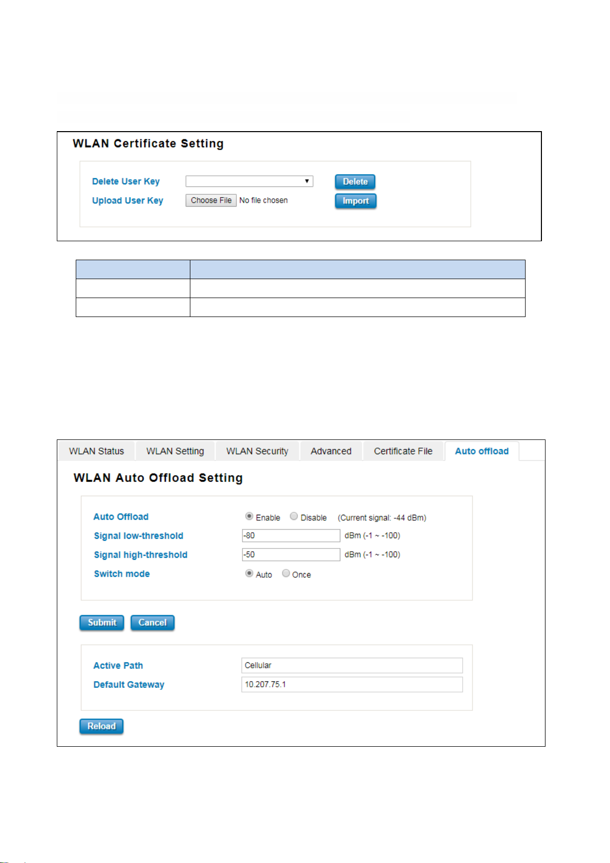
3.7.7 CERTIFICATE FILE (CLIENT MODE)
Using digital certificates for authentication method through the RADIUS that provided by the AP. User needs to
upload the specific certificate file, so then the client can access the Wi-Fi connection.
The description of the columns is as below:
TERMS DESCRIPTION
Delete User Key Delete the selected certificate
Upload User Key Upload a certificate file from a specified file location
3.7.8 AUTO OFFLOAD (CLIENT MODE)
The WoMaster Router Client mode is supported by the Auto Offload feature that allows the user to enable Wireless
Auto Offload. User need to make sure if the device has two available connections, Wi-Fi and Cellular. The cellular cost
can be reduced by using this feature because the data traffic can be shared by Cellular and Wi-Fi. If the W i-Fi signal is
poor, then the system forwards the traffic to the Cellular interface automatically.
69
Page 70

When signal strength is higher than the upper range, then the connection
, the connection will automatically
The description of the interface is as below:
TERMS DESCRIPTION
Auto Offload Default: Disable
Enable or Disable Auto Offload feature. This feature can be activated when
the Wi-Fi is configured as the client mode and the Cellular interface is
established. And it will show the current signal strength.
Signal low-threshold Default: -80 dBm (Range: -1 ~ -100 dBm)
When signal strength is lower than the upper range, then the connection
will be directed to Cellular.
Signal high-threshold Default: -50 dBm (Range: -1 ~ -100 dBm)
will be directed to Wi-Fi.
Switch mode Default: Auto
When user chooses the Auto mode
switch to the stronger signal between Wi-Fi or Cellular. If user chooses to
Once mode, it means the connection will switch to the stronger signal once
between Wi-Fi or Cellular and will stay at the connection even there were a
stronger signal appear.
Active Path Show the current active path between Wireless or Cellular.
Default Gateway Show the default gateway IP Address.
70
Page 71
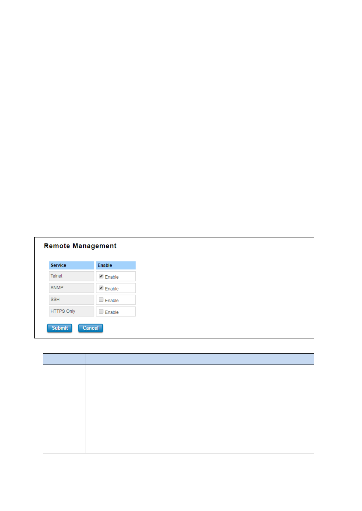
3.8 SECURITY
WoMaster Router provides several security features for User to secure access to its management functions and it
can be remotely managed (monitored and configured).
The following topics are included in this section:
3.8.1 Access Control
3.8.2 Outbound Firewall
3.8.3 NAT Setting
3.8.4 OpenVPN
3.8.5 IPSec Setting
3.8.6 GRE Setting
3.8.1 ACCESS CONTROL
WoMaster router provides access control mode in several ways, such as Remote Management, WAN Service Access
Control and Custom Exception. By configuring this configuration, user can enhance the security access to the device.
Remote Management
Remote Management function, open the Remote Management, that would allow the user via the local access (WAN
Port) Remote Management the router.
The description of the columns is as below:
TERMS DESCRIPTION
Telnet Allows the user to remotely login and manage the device by Telnet. When user doesn’t
enable it, the connection through telnet will not allow.
SNMP Allows the user to remotely login and manage the device by SNMP. When user doesn’t
enable it, the connection through SNMP will not allow.
SSH Allows the user to remotely login and manage the device by SSH/ When user doesn’t
enable it, the connection through SSH will not allow.
HTTPS Only Allows the user to remotely login and manage the device by HTTPS access for secure
connection, and it would disable the HTTP access.
Once User finishes configuring the settings, click on Submit to apply configuration.
71
Page 72
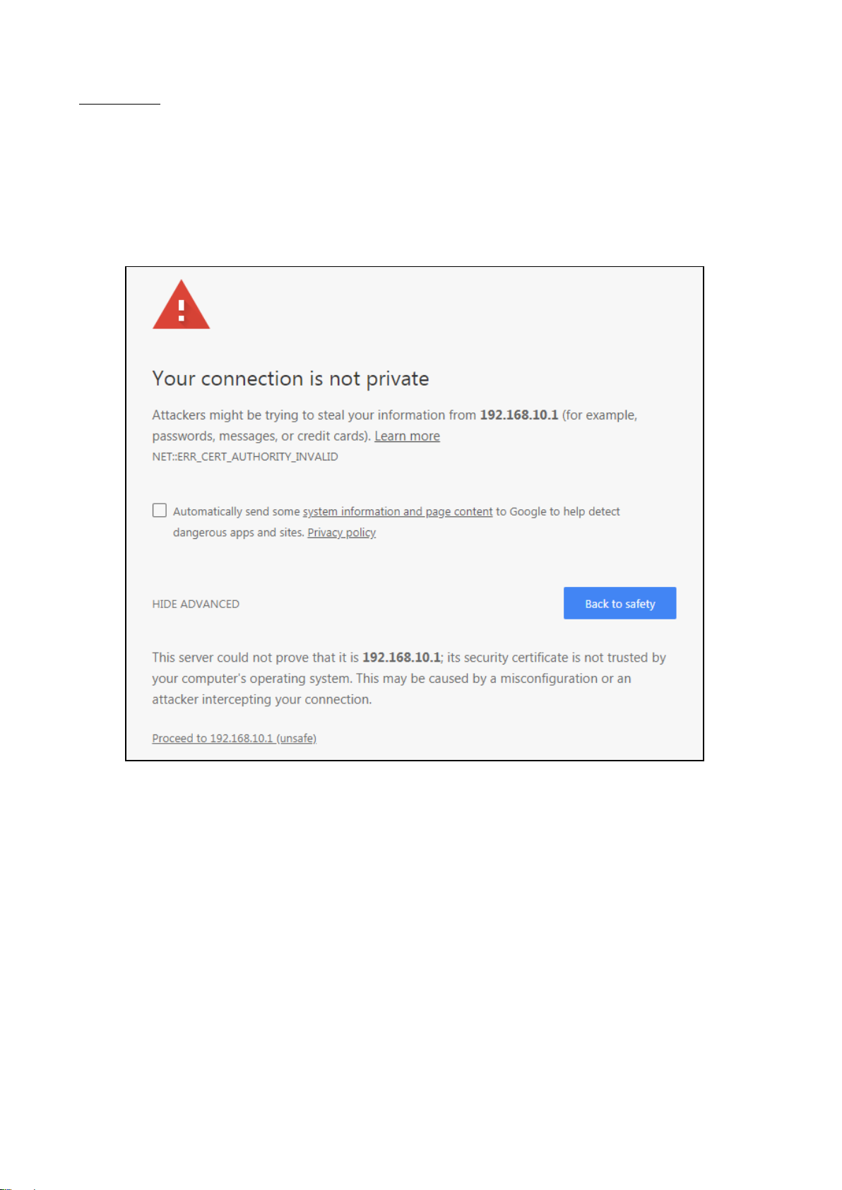
HTTPS Only
HTTP Secure is the use of the HTTP protocol over an SSL/TLS protocol. It is used primarily to protect against
eavesdropping of communication between a web browser and the web site to which it is connected. This is especially
important when you wish to have a secure connection over a public network such as the internet. HTTPS connections
are secured through the use of certificates issued by trusted certificate authorities. When a web browser makes a
connection attempt to a secured web site, a digital certificate is sent to the browser so that it can verify the
authenticity of the site using a built-in list of trusted certificate authorities.
If user uses the HTTPS Only, a warning page would appear when user access the device in order to provide a secure
access. The picture above is the warning message about the digital certificate and user just need to accept this
warning by click “Proceed to 192.168.10.1 (unsafe)”.
72
Page 73
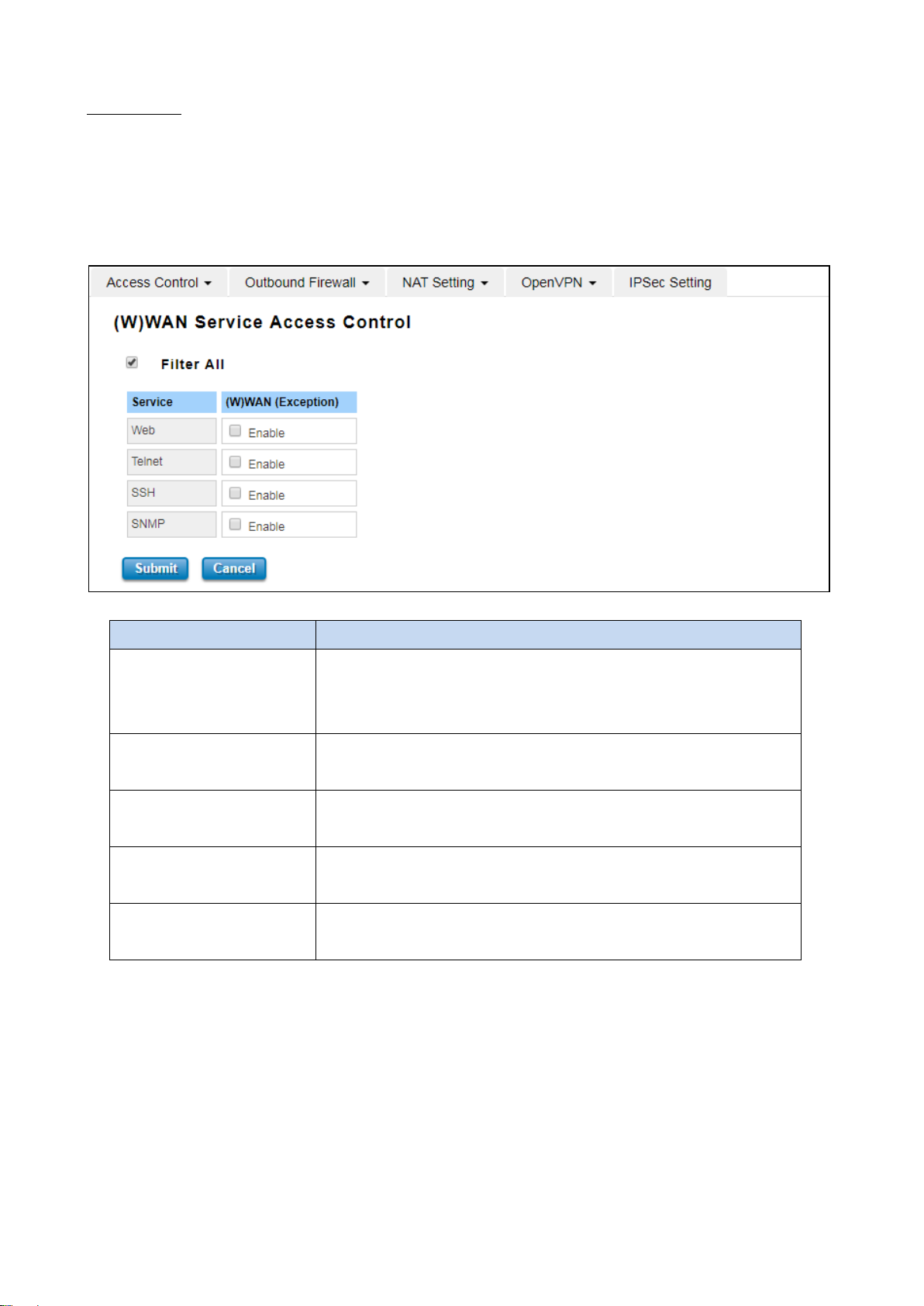
and unblock the
WAN Access
When user changes the device mode to router mode (Port 1 – WAN interface) the WAN Access feature can be
activated. This feature is about the exception to access the device through the WAN interface for security concern. So
that the access or the traffic that coming through the WAN interface can be limited as required. The user may choose
the Filter All functions to block all access from the WAN interface or enable the exception options, then the router
allows user to remotely access to the router from WAN interface.
The description of the columns is as below:
TERMS DESCRIPTION
Filter All By select Filter All, it will block all external access from WAN interface to
the device (such as SSH, SNMP, Web and Telnet)
exception options.
Web Select this option to allow access to the router using Web (HTTP or HTTPS)
from the WAN Interface
Telnet Select this option to allow access to the router using Telnet from the WAN
Interface
SSH Select this option to allow access to the router using SSH from the WAN
Interface
SNMP Select this option to allow access to the router using SNMP from the WAN
Interface
Once User finishes configuring the settings, click on Submit to apply configuration.
73
Page 74
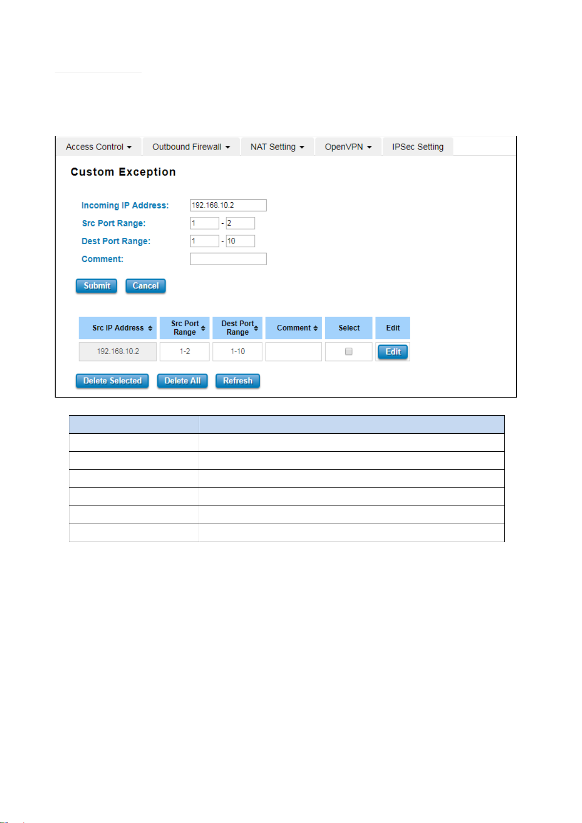
Custom Exception
Another choice for the access control is also provided by WoMaster, it is called custom exception feature. Through
this feature, it can help to allow the incoming access through the firewall to local devices. If the condition does not
meet the requirement from the table, then the access would be denied.
The description of the columns is as below:
TERMS DESCRIPTION
Src IP Address Set up the source IP Address that may access the device.
Src Port Range Set up the source port range where the access came from.
Dest Port Range Set up the destination port range where the access is going to.
Comment Put any notes for the entry.
Select Select the table, so user can press Delete Selected to delete,
Edit Click edit to modify the parameters
Once User finishes configuring the settings, click on Submit to apply configuration and a new line will directly appear
on the table.
74
Page 75
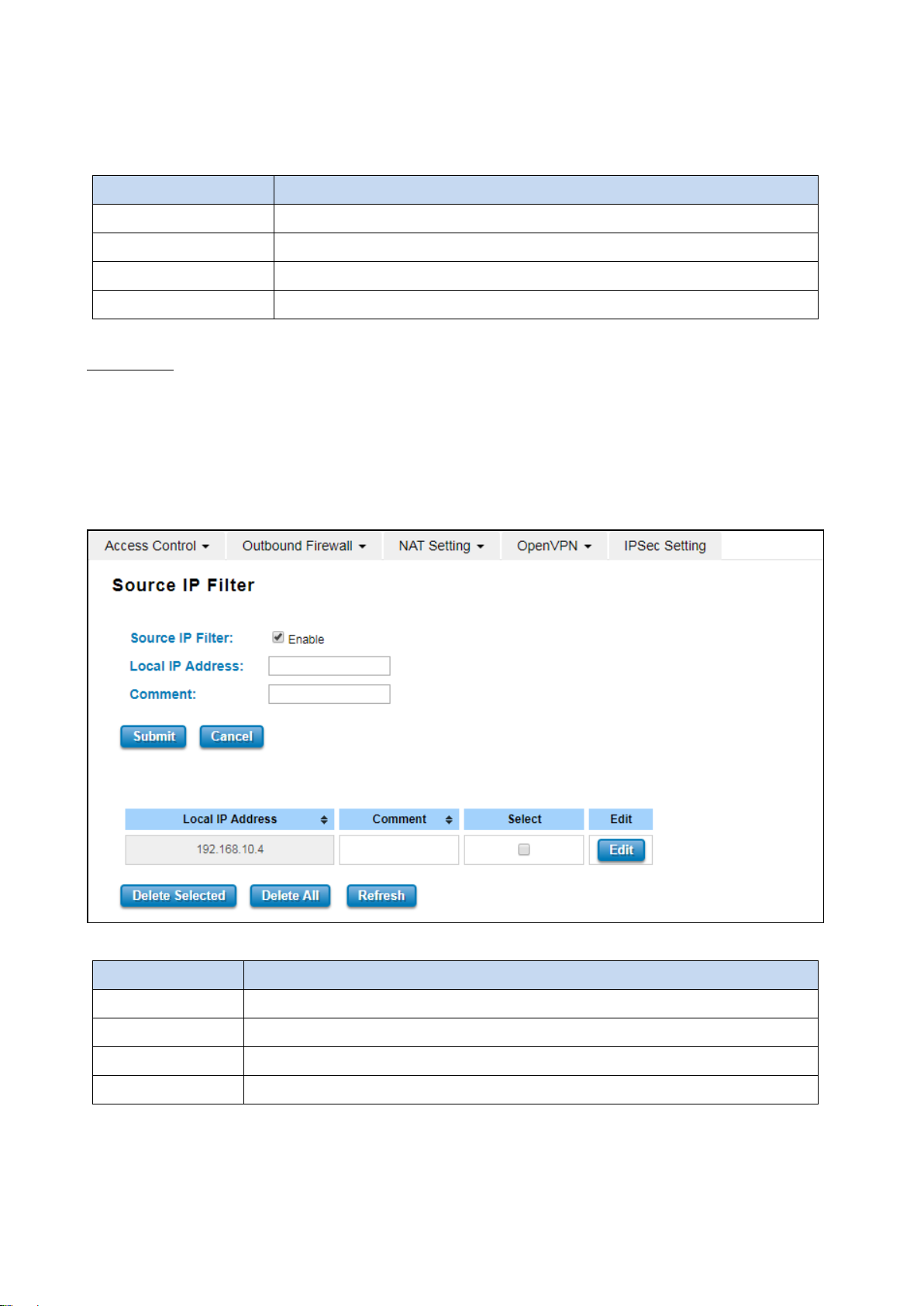
3.8.2 OUTBOUND FIREWALL
WoMaster’ router has different types firewall settings, user can enable the setting, configure the rules. The following
section is Outbound Firewall Settings pages where user can configure the Outbound Firewall setting.
TERMS DESCRIPTION
Source IP Filter Source IP addresses Filtering from LAN to Internet through the router.
Destination IP Filter Destination IP addresses Filtering from the LAN to Internet through the router.
Source Port Filtering Source Ports Filtering from the LAN to Internet through the router.
Destination Port Filtering Destination Ports Filtering from the LAN to Internet through the router
Src IP Filter
By entries parameter in this table, it can restrict certain types of data packets from the local network to the internet
through the Router. The Source IP Filter will help to filter all of the packets that coming into the router. If the source
IP is on the list, then the packets would be dropped. But if the source IP is not on the list, then the packets can be
received. Select Enable to activate Source IP Filtering, type the Local IP Address and Comment to write notes for the
entry. Click Submit to activate the settings. After applied, then user can see the new entry shown in the below table.
The description of the columns is as below:
TERMS DESCRIPTION
Local IP Address Display the Source IP address.
Comment Put any notes for the entry.
Select Select the table, so user can press Delete Selected to delete,
Edit Click edit to modify the parameters
Click Refresh to refresh the table
75
Page 76
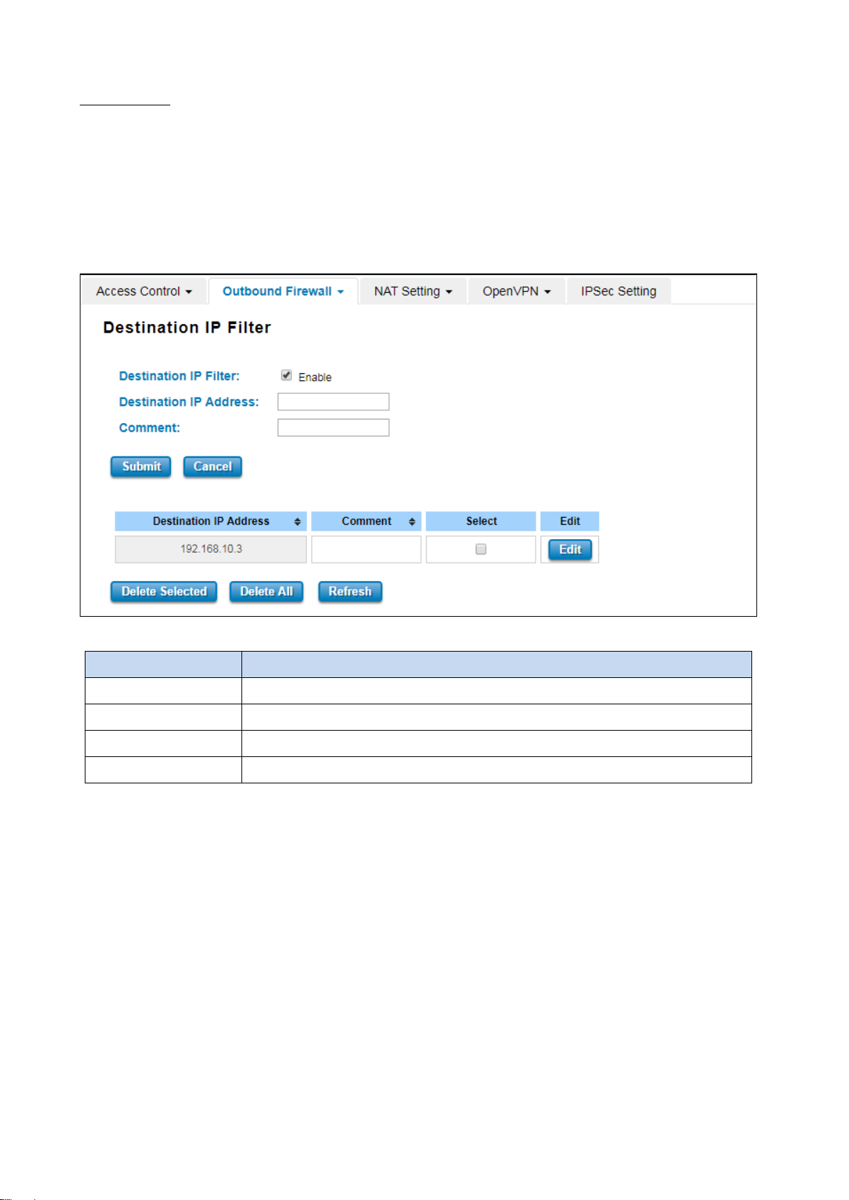
Dest IP Filter
By entries parameters in this table are used to restrict the computers in LAN from accessing certain websites in WAN
according to IP address. The concept is the same as the source IP Filter. The packet would not send to the specific IP
Address that showed on the list. Only the IP Address that shows on the list that cannot receive the packets. Select
Enable to activate Destination IP Filtering, type the Destination IP Address and Comment to write a note for the
entry and then click Submit to apply the settings. After applied, then user can see the new entry shown in the below
table.
The description of the columns is as below:
TERMS DESCRIPTION
Destination IP Address Display the Destination IP address.
Comment Put any notes for the entry.
Select Select the table, so user can press Delete Selected to delete,
Edit Click edit to modify the parameters
Click Refresh to refresh the table
76
Page 77
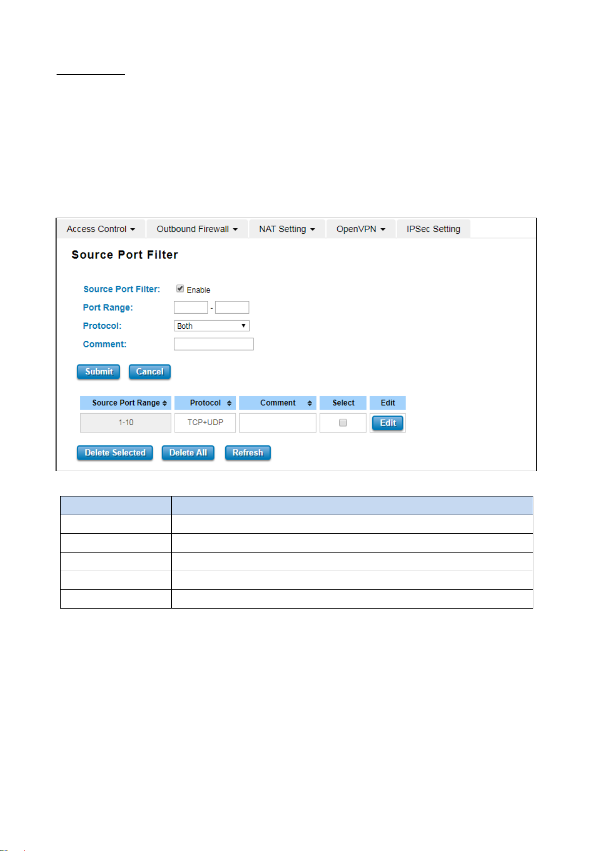
Src Port Filter
Entries in this table are used to restrict certain ports of data packets from user’s local network to the Internet
through the Router. Use of such filters can be helpful in securing or restricting local network. The device just cannot
receive any packets from the source port that showed on the list, the other packet that sent from any source port
that not on the list would be received.
Select Enable Source Port filtering, type the Port Range of below Protocol type, the protocol type can be UDP, TCP
or Both. Type the Comment to write a note for the entry and then click Submit to activate the settings.
After applied, user can see the new entry shown in the below table.
The description of the columns is as below:
TERMS DESCRIPTION
Source Port Range Display the Source Port Range (Range is from 1 to 65535)
Protocol Display the protocol that has been chosen by the user.
Comment Put any notes for the entry.
Select Select the table, so user can press Delete Selected to delete,
Edit Click edit to modify the parameters
Click Refresh to refresh the table
77
Page 78
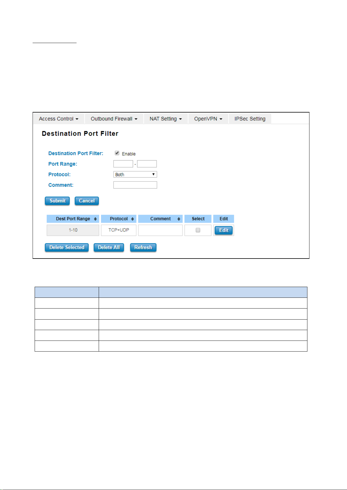
Dest Port Filter
Entries in this table are used to restrict certain ports of data packets from user’s local network to Internet through
the router. Use of such filters can be helpful in securing or restricting local network. And the device cannot send any
packets to the destination port that showed on the list.
Select Enable Destination Port Filtering, type the Port Range of below Protocol type, the protocol type can be U D P,
TCP or Both. Type the Comment to write note for the entry and then press Submit to apply the settings.
After applied, then user can see the new entry shown in the below table.
The description of the columns is as below:
TERMS DESCRIPTION
Dest Port Range Display the Destination Port Range (Range is from 1 to 65535)
Protocol Display the protocol that has been chosen by the user.
Comment Put any notes for the entry.
Select Select the table, so user can press Delete Selected to delete,
Edit Click edit to modify the parameters
Click Refresh to refresh the table
78
Page 79
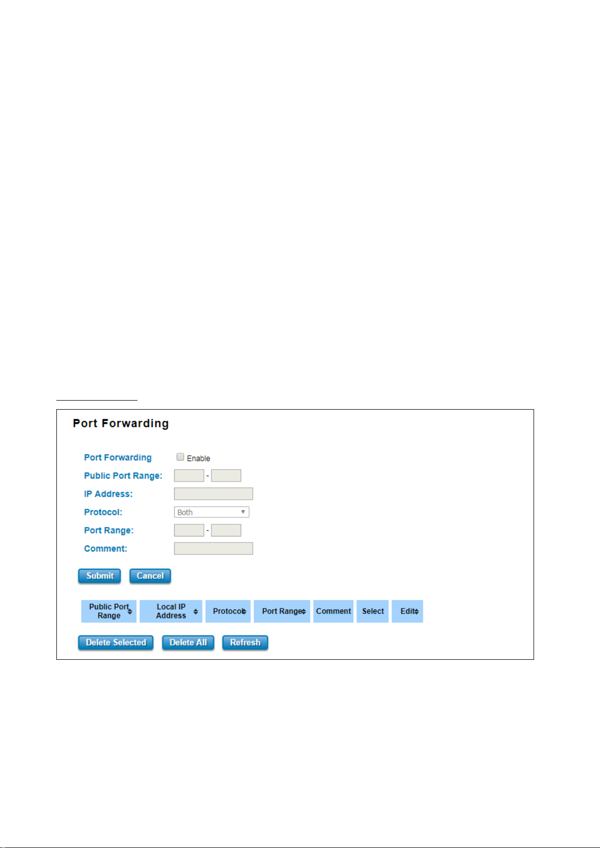
3.8.3 NAT SETTING
Network Address Translation is the process where a network device, usually a firewall, assigns a public address to a
device or group of devices inside a private network. The main use of NAT is to limit the number of public IP addresses
an organization or company must use, for both economic and security purposes. The simple type of NAT provides
one to one translation of IP address. It can be used to interconnect two IP networks, normally one network is for
Local Area Network and the other network is for Wide Area Network/Internet. To support this function, there are
two ways to do it, by using Source Network Address Translation (SNAT), Destination Network Address Translation
(DNAT). Basically, Network Address Translation (NAT) occurs when one of the IP addresses in an IP packet header is
changed. In a SNAT, the destination IP address is maintained and the source IP address is changed. Most commonly, a
SNAT allows a host on the “inside” of the NAT, in an RFC 1918 IP address space, to initiate a connection to a host on
the “outside” of the NAT. It supports the Port Forwarding, DMZ and 1 to 1 NAT configuration. A DNAT, by way of
contrast, occurs when the destination address is changed and the source IP address is maintained. A DNAT allows a
host on the “outside” to connect to a host on the “inside”. In both cases, the NAT has to maintain a connection table
which tells the NAT where to route returning packets. An important difference between a SNAT and a DNAT is that a
SNAT allows multiple hosts on the “inside” to get to any host on the “outside”. By way of contrast, a DNAT allows any
host on the “outside” to get to a single host on the “inside”. It is supported in NAPT and 1 to 1 NAT features.
To configure the NAT Setting, the Port Forwarding, DMZ, Port Mapping Policy and 1 to 1 NAT configuration page are
provided in this section.
Port Forwarding
By configuring this table, it allows user to automatically redirect common network services to a specific machine
behind the NAT firewall. Select Enable to activate Port Forwarding function and then input all of the parameters to
configure the port forwarding.
79
Page 80
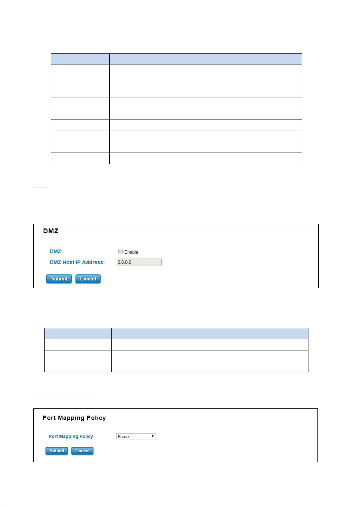
Configure the IP Address of the LAN PC. The traffic from the public port
The description of the columns is as below:
TERMS DESCRIPTION
Port Forwarding Select Enable to activate Port Forwarding function.
Public Port Range Configure the port range, which will be public to a WAN / Internet. User can
configure one or a range of TCP/UDP port number.
IP Address
range will be redirected to this IP address.
Protocol Configure TCP, UDP or Both (TCP + UDP) protocol type.
Port Range Configure the port range of the LAN; the traffic from the public port will be
redirected to these ports.
Comment Add information to the entry.
Once User finishes configuring the settings, click on Submit to apply User configuration.
DMZ
A Demilitarized Zone is used to provide Internet services without sacrificing unauthorized access to its local private
network. Typically, the DMZ host contains device accessible to Internet traffic, such as Web (HTTP) servers, FTP
servers, SMTP (e-mail) servers and DNS servers.
Click Enable to activate the function and assign the IP address of DMZ Host IP Address. This is the DMZ computer’s IP
address. Click Submit to activate the function.
The description of the columns is as below:
TERMS DESCRIPTION
DMZ Select Enable to activate DMZ function.
DMZ Host IP Address Configure the port range, which will be public to a WAN / Internet. User can
configure one or a range of TCP/UDP port number.
Port Mapping Policy
This page allows user to configure the Port Mapping policy from NAT Setting.
80
Page 81
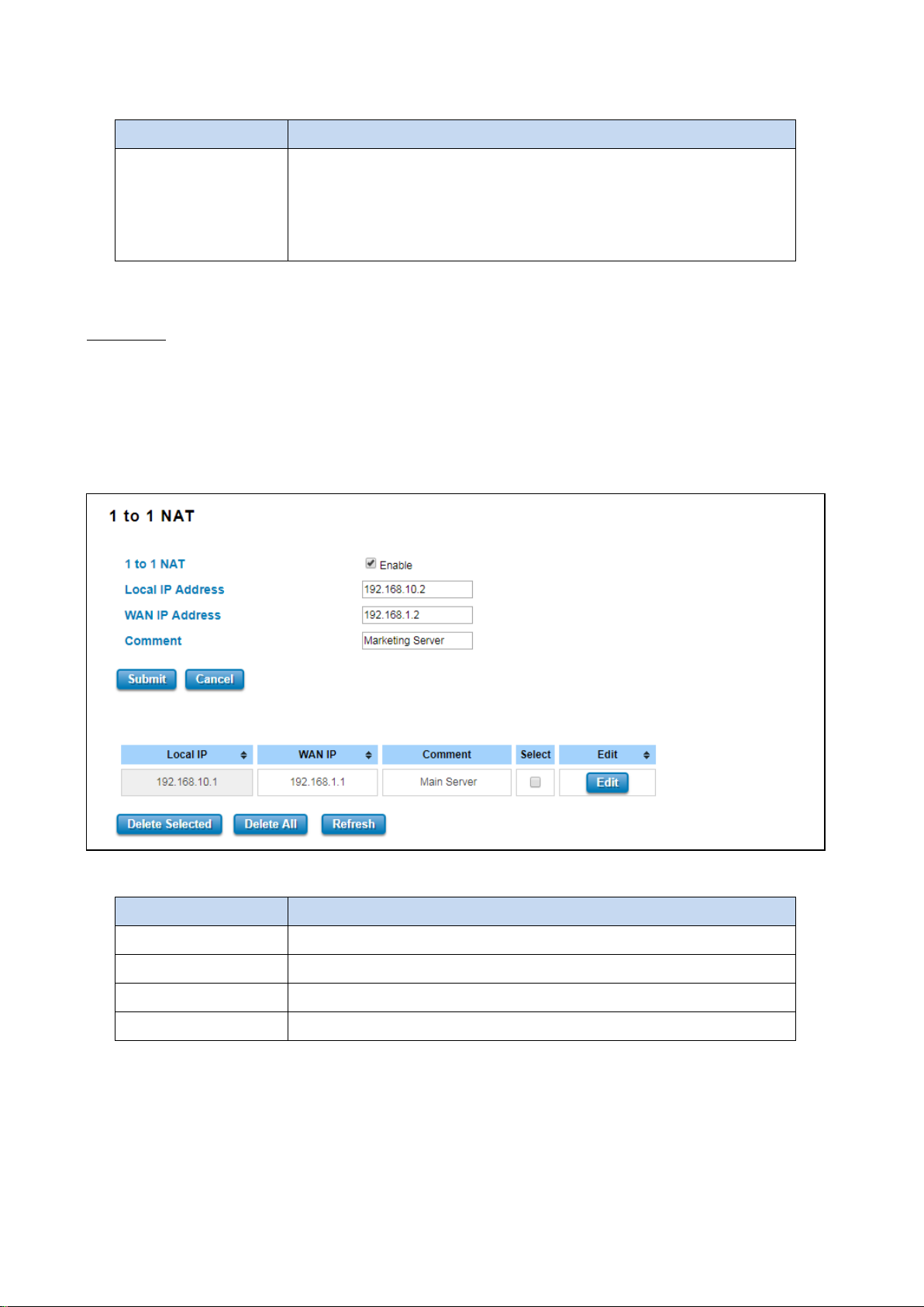
The description of the columns is as below:
TERMS DESCRIPTION
Port Mapping Policy Default: Reuse
Reuse: Use the same port number that has been used to access the same
remote device.
Randomize: Change the port number every time access the remote device.
Click Submit to apply the configuration.
1 to 1 NAT
One-to-one NAT is a way to make systems behind a firewall and configured with private IP addresses (those reserved
for private use in RFC 1918) appear to have public IP addresses.
With one-to-one NAT, you assign local systems RFC
1918 addresses then establish a one-to-one mapping between those addresses and public IP addresses. For outgoing
connections SNAT (Source Network Address Translation) occurs and on incoming connections DNAT (Destination
Network Address Translation) occurs. Below is the 1 to 1 NAT section interface.
The description of the columns is as below:
TERMS DESCRIPTION
1 to 1 NAT Check the box to enable the function
Local IP Address The target local IP Address
WAN IP Address The incoming IP Address that coming through the WAN
Comment Enter a comment
Click Submit to apply the configuration.
81
Page 82
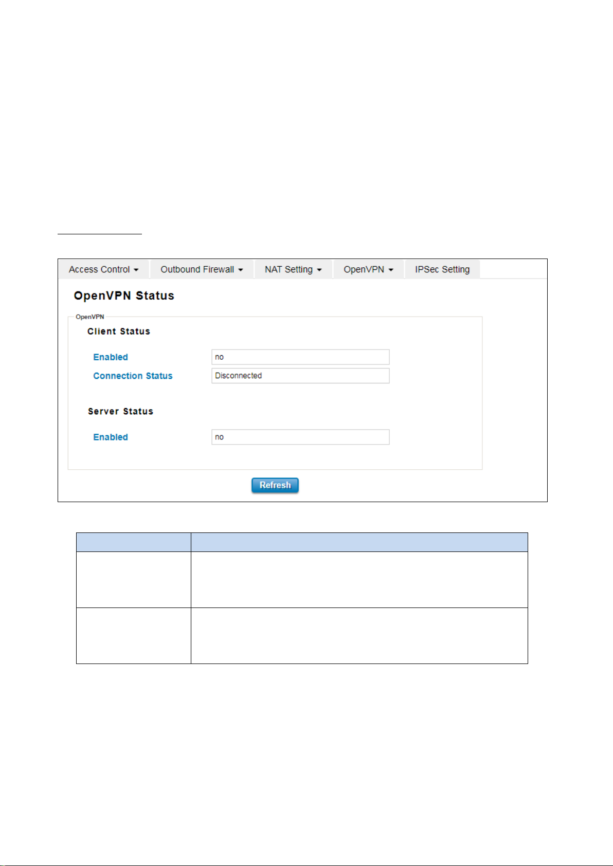
3.8.4 OPEN VPN
WoMaster router supports OpenVPN. It implements virtual private network (VPN) techniques for creating secure
point-to-point or site-to-site connections. It is possible to create one-to-many tunnel for the VPN Server. OpenVPN
implementation offers a cost-effective, simply configurable alternative to other VPN technologies. OpenVPN allows
peers to authenticate each other using a pre-shared secret key, certificates, or username/password. The server and
client have almost the same configuration. The difference in the client configuration is the remote endpoint IP or
hostname field. Also, the client can set up the keepalive settings.
OpenVPN Status
This section shows the VPN Client and Server current status.
The description of the columns is as below:
TERMS DESCRIPTION
Enabled Default: no
yes: The VPN function is enabled.
no: The VPN function is not enabled
Connection Status Default: Disconnected
Connected: The VPN connection is established
Disconnected: The VPN connection is not established
Click Refresh to update the information.
82
Page 83
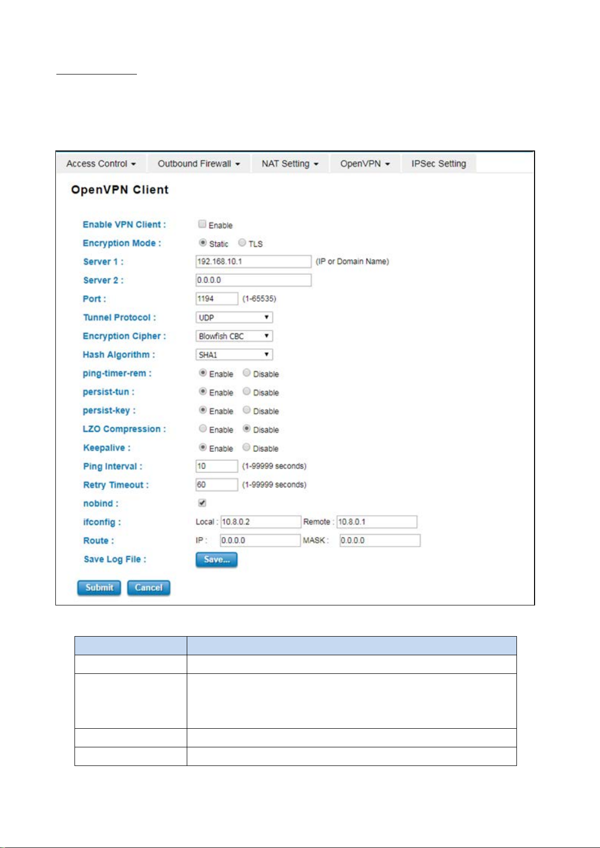
OpenVPN Client
This page is about the OpenVPN Client configuration page. While the device set as the VPN client, the parameters
must follow the VPN Server settings. User should adjust the parameters with the administrator of the VPN server to
entry the correct parameters. Two VPN servers IP are also provided in order to have the backup connection for VPN
Server.
The description of the columns is as below:
TERMS DESCRIPTION
Enable VPN Client Select Enable to activate the VPN Client function
Encryption Mode Choose the Encryption Mode
Static Key: Use a pre-shared static key.
TLS: Use SSL/TLS + certificates for authentication and key exchange.
Server 1 Type the IP Address of the VPN Server
Server 2 Type the second IP Address of the VPN Server if needed.
83
Page 84

Port Default: 1194
Input the port number that VPN service used. Please check the VPN Server
port setting. The range from 1-65535.
Tunnel Protocol Choose use TCP or UDP to establish the VPN connection.
Encryption Cipher Select the encryption cipher from Blowfish to AES in Pull-down menus.
Hash Algorithm
ping-timer-rem Default: Enable
persist-tun Default: Enable
persist-key Default: Enable
LZO Compression Default: Disable
Keepalive Default: Enable
Hash algorithm provides a method of quick access to data, including SHA1,
SHA256,SHA512,MD5
Select enable or disable the ping-timer-rem, this function prevent
unnecessary restart at server/client when network fail.
Select enable or disable the persist-tun, enable this function will keep
tun(layer 3) device linkup after Keepalive timeout.
Select enable or disable the persist-key, enable this function will keep the key
first use if VPN restart after Keepalive timeout.
Select use LZO Compression or not, this function compresses data to decrease
the traffic but also need more CPU effort.
Select enable or disable Keepalive function, this function is use to detect the
status of connection.
Ping Interval Default: 10
Input the ping interval, the range can from 1~99999 seconds.
Retry Timeout Default: 60
Input the retry timeout, the range can from 1~99999 seconds.
nobind Check the box to activate nobind function. With nobind function, the source
ports are random.
ifconfig Input the tunnel IP addresses that VPN use.
Route Input the route IP and MASK. This is the target IP domain that user can access
through the VPN tunnel.
Save Log File Click Save to keep the VPN Client Log.
Click Submit to apply the configuration.
84
Page 85
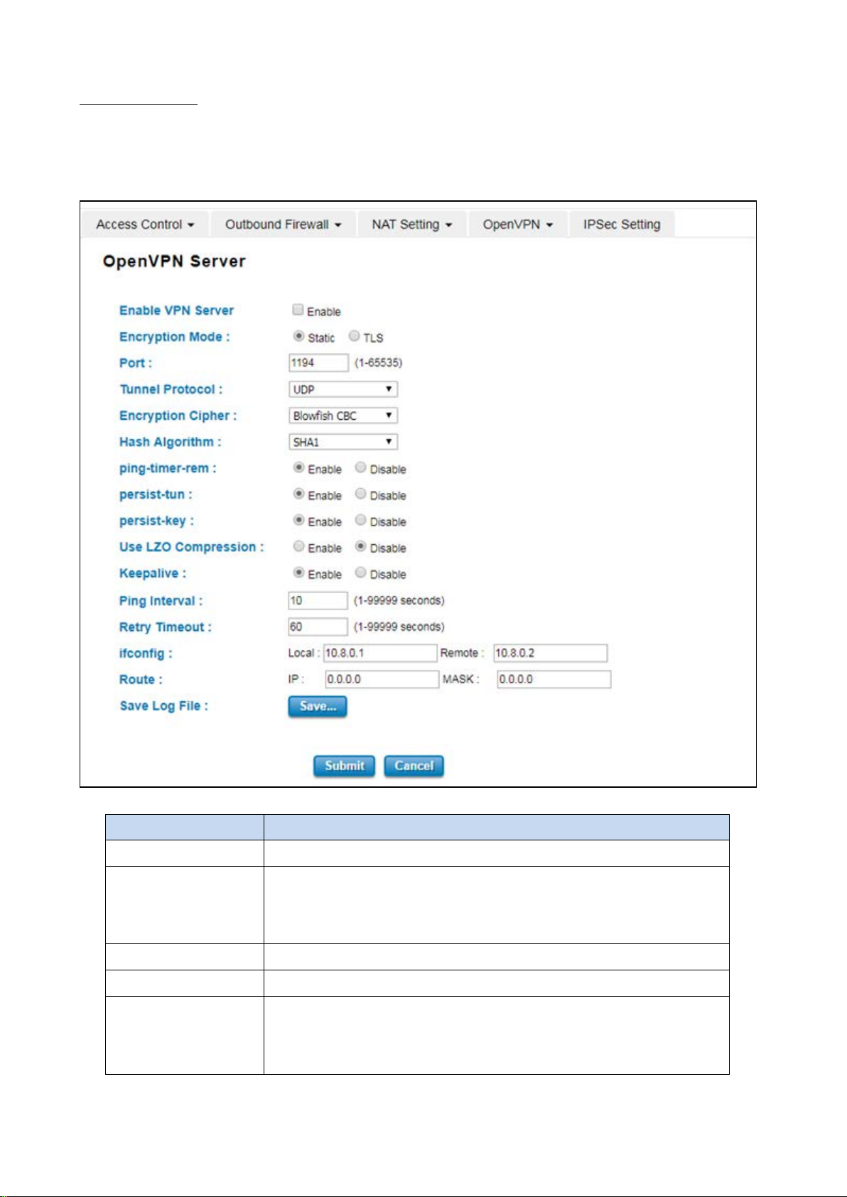
OpenVPN Server
To help user create the One to One Secure connection for the remote devices, WoMaster device supports both
OpenVPN Server and OpenVPN Client. This Server setting allows user to configure the Secure M2M connection for
one remote Client. But WoMaster router also supports one to multiple for VPN Client.
The description of the columns is as below:
TERMS DESCRIPTION
Enable VPN Server Select Enable to activate the VPN Server function
Encryption Mode Choose the Encryption Mode
Static Key: Use a pre-shared static key.
TLS: Use SSL/TLS + certificates for authentication and key exchange.
Server 1 Type the IP Address of the VPN Server
Server 2 Ty pe the second IP Address of the VPN Server if needed.
Port Default: 1194
Input the port number that VPN service used. Please check the VPN Server
port setting. The range from 1-65535.
85
Page 86

Tunnel Protocol Choose use TCP or UDP to establish the VPN connection.
Encryption Cipher Select the encryption cipher from Blowfish to AES in Pull-down menus.
Hash Algorithm Hash algorithm provides a method of quick access to data, including SHA1,
SHA256, SHA512, and MD5
ping-timer-rem Default: Enable
Select enable or disable the ping-timer-rem, this function is to prevent
unnecessary restart at server/client when the network fails.
persist-tun Default: Enable
Select enable or disable the persist-tun, enable this function will keep
tun(layer 3) device linkup after Keepalive timeout.
persist-key Default: Enable
Select enable or disable the persist-key, enable this function will keep the key
first use if VPN restart after Keepalive timeout.
LZO Compression Default: Disable
Select use LZO Compression or not, this function compresses data to decrease
the traffic, but also need more CPU effort.
Keepalive Default: Enable
Select enable or disable Keepalive function, this function is used to detect the
status of the connection.
Ping Interval Input the ping interval, the range can from 1~99999 seconds.
Retry Timeout Input the retry timeout, the range can from 1~99999 seconds.
ifconfig Input the tunnel IP addresses that VPN use.
Route Input the route IP and MASK. This is the target IP domain that user can access
through the VPN tunnel.
Save Log File Click Save to keep the VPN Server Log.
Click Submit to apply the configuration.
86
Page 87
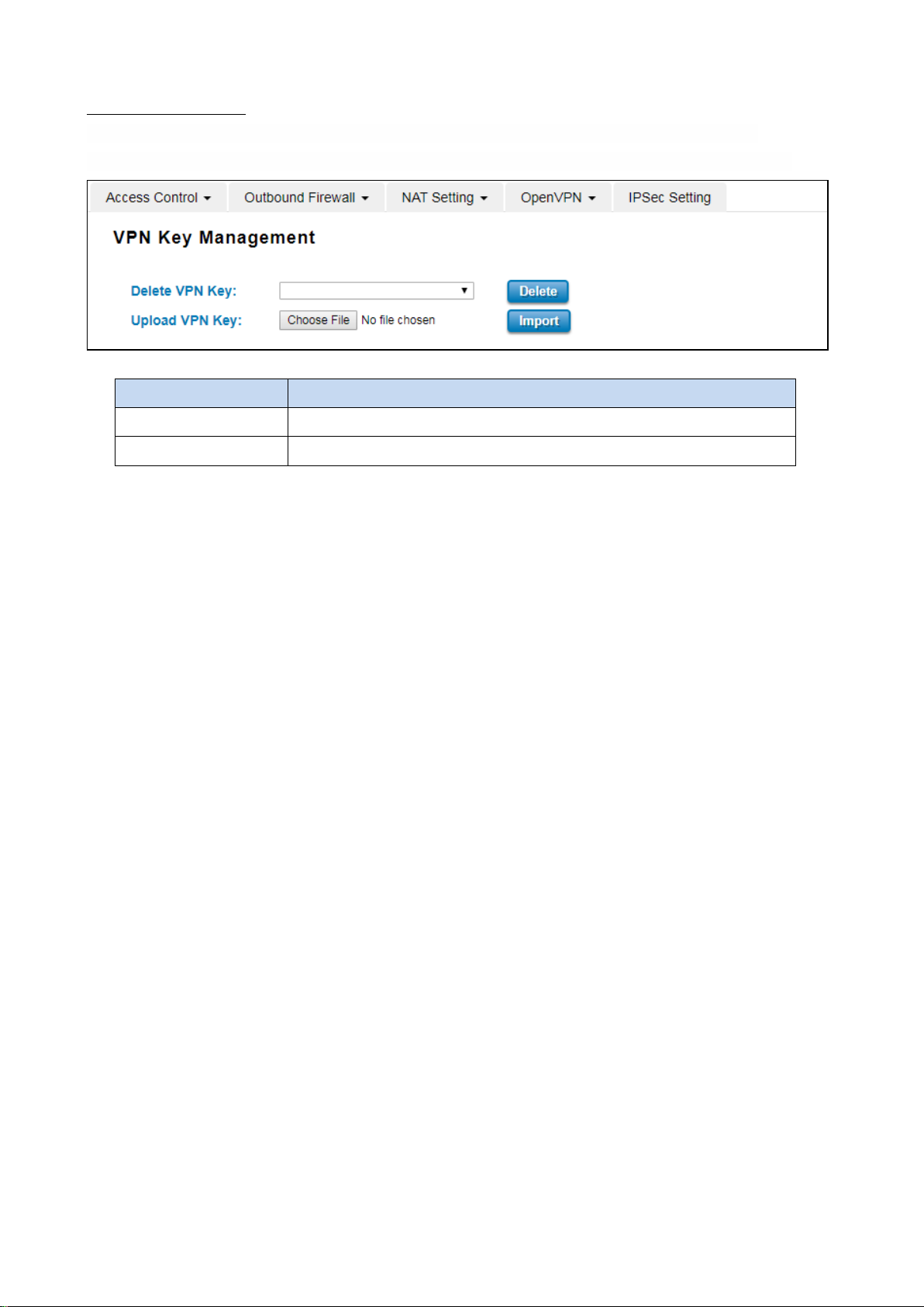
OpenVPN Certificate
Using digital certificates for authentication instead of preshared keys in VPNs is considered more secure. In
WoMaster’ devices, digital certificates are one way of authenticating two peer devices to establish a VPN tunnel.
The description of the columns is as below:
TERMS DESCRIPTION
Delete VPN Key Delete the selected certificate
Upload VPN Key Upload a certificate file from a specified file location
87
Page 88
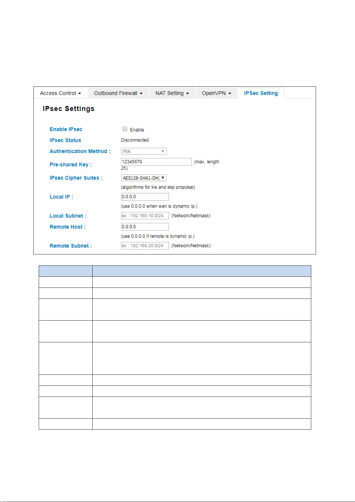
3.8.5 IPSEC SETTING
Internet Protocol Security (IPsec) is a protocol suite for securing Internet Protocol (IP) communications by
authenticating and encrypting each IP packet of a communication session. By configure this configuration page, user
allows IPsec tunnels to pass through the router.
The description of the columns is as below:
TERMS DESCRIPTION
Enable IPsec Select Enable to activate the IPsec function
IPsec Status Display the IPsec status, whether it is connected or disconnected
Authentication
Method
Pre-shared key Default: 12345678
IPsec Cipher Suites Default: AES128-SHA1-DH2
Local IP IP Address of the local side of the tunnel. (Use 0.0.0.0 when WAN is dynamic IP. )
Local Subnet Set IPSec local protected subnet and subnet mask, i.e. 192.168.1.0/24
Remote Host Default: 0.0.0.0
Remote Subnet Set IPsec Remote Protected Subnet/Subnet Netmask
Default: PSK
Optional: Pre Shared Key or Certificate
Set the preshared key
Set algorithms for IKE and ESP proposal, choose AES128-SHA1-DH2, DES-SHA1-DH2 and
3DES-SHA1-DH2
Set IPsec Remote Host, use the default setting if remote is dynamic IP
Click Submit to apply the configuration.
88
Page 89
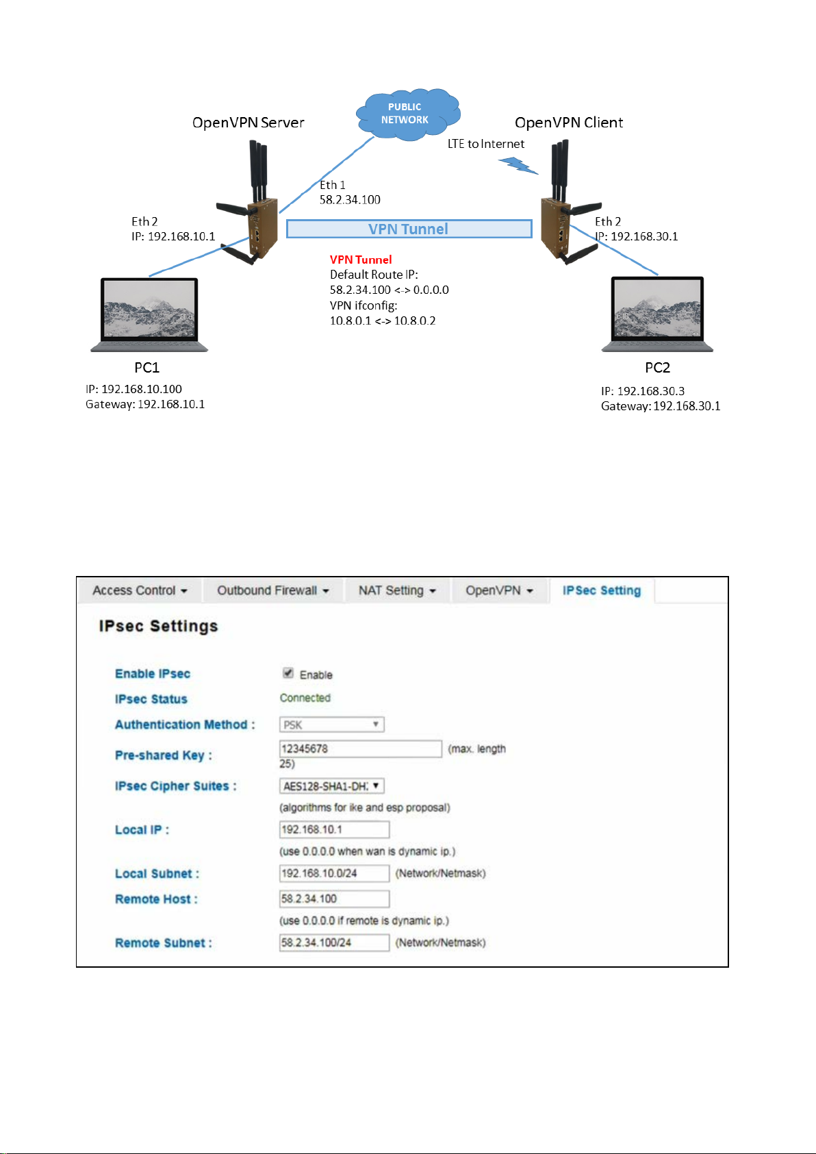
The topology above is about how the branch office can get the access to the headquarter server. The two laptops are
connected to the device using the Ethernet cable.
The laptop at the branch office picks a role as the VPN Client and the laptop at headquarter picks a role as the VPN
Server. To get the access to the server the branch office need to connect to the VPN Server. As we can see the
connection is established through the LTE connection. In this case, IPsec connection needs to be enabled. See the
setting below.
When the connection is enabled, then the IPsec status will directly change to connected status, which means that
the connection is established. So that the laptop at the branch office can access the server at headquarter.
89
Page 90
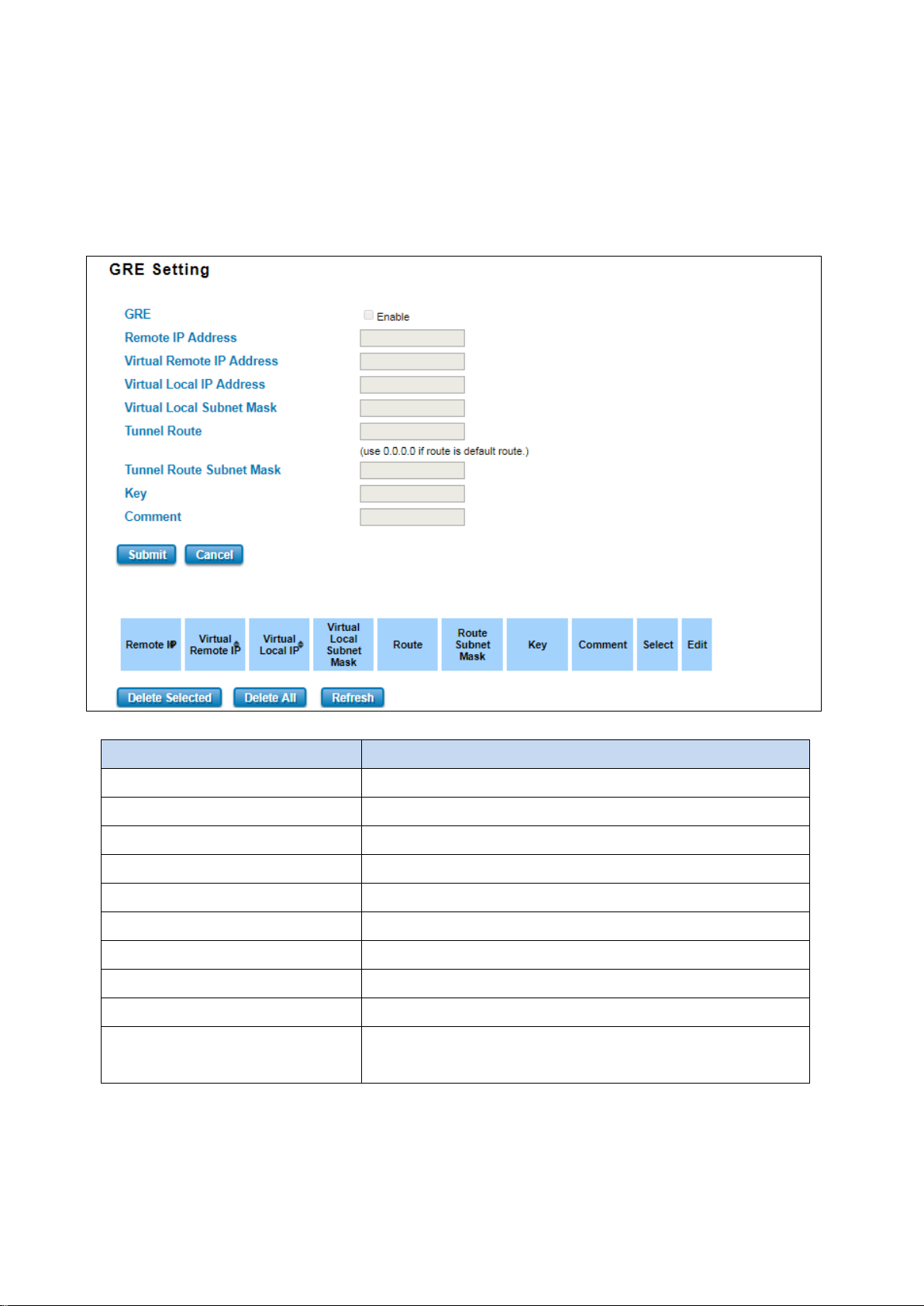
3.8.6 GRE SETTING
GRE (Generic Routing Encapsulation RFC2784) is a solution for tunneling RFC1812 private address-space traffic over
an intermediate TCP/IP network such as the Internet. GRE tunneling does not use encryption it simply encapsulates
data and sends it over the WAN port only. This page allows user to set up GRE tunnels and view information about
the amount of data transmitted and received.
The description of the column is as below:
TERMS DESCRIPTION
GRE Check the box to enable the function.
Remote IP Address Set the remote real IP Address of the GRE Tunnel
Virtual Remote IP Address Set the remote virtual IP Address of the GRE tunnel.
Virtual Local IP Address Set the local virtual IP Address of the GRE tunnel.
Virtual Local Subnet Mask Set the remote virtual Netmask of the GRE tunnel.
Tunnel Route Route, the default value is 0.0.0.0
Tunnel Route Subnet Mask Set the subnet mask for the route
Key Enter the key for the GRE tunnel.
Comment Enter any comment to describe the configuration.
Select Select the list on the table, so user can press Edit or Delete Selected
to delete.
Click the Refresh button to refresh the list.
90
Page 91
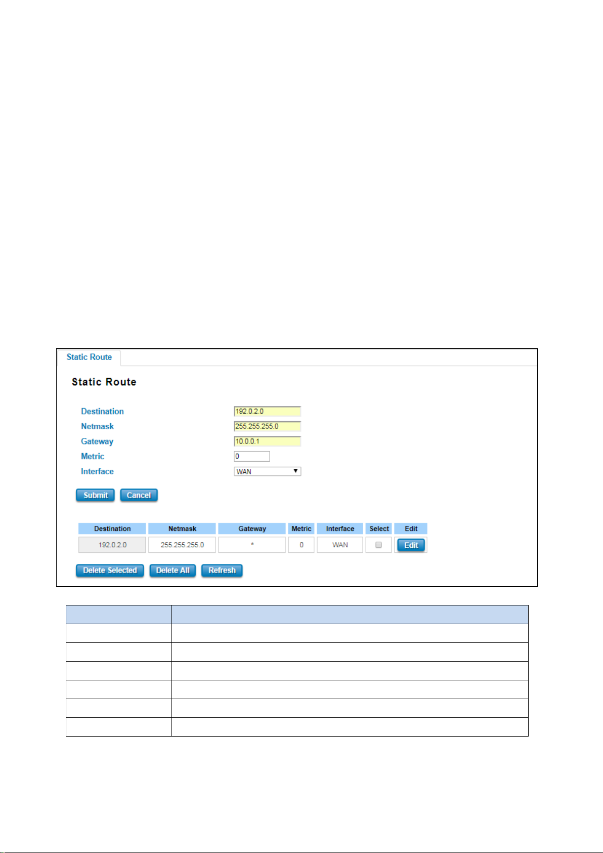
3.9 ROUTING
Layer 3 routing feature is requested since the hosts located in different broadcast domain can’t communicate each
other.
The WoMaster Industrial Router is supported with two routing methods: static routing and dynamic routing.
Dynamic routing makes use of RIPv2. The user can choose one routing method or combine the two methods to
establish the routing table. In this Routing pages allows users create the Static Route and RIPv2 to do the routing.
3.9.1 STATIC ROUTE
A static route is a route that is created manually by a network administrator. Static routes are typically used in
smaller networks. In static routing, the Router's routing table entries are populated manually by a network
administrator. The opposite of a static route is a dynamic route. In dynamic routing, the routing table entries are
populated with the help of routing protocols.
The major advantages of static routing are reduced routing protocol router overhead and reduced routing protocol
network traffic. The major disadvantages of static routing are network changes require manual reconfiguration in
routers and network outages cannot be automatically routed around. Also it is difficult to configure static routing in
a complex network. Below is the Static Route section interface.
The description of the column is as below:
TERMS DESCRIPTION
Destination The Destination network IP address. For example,192.168.10.0
Netmask Destination network’s subnet mask.
Gateway Gateway. Factory default is blank (0.0.0.0).
Metric Assigns a cost to each available route so that the most cost-effective path can be.
Interface The outgoing network interface. LAN, WAN, and Cellular are available to setup here.
Select Select the list on the table, so user can press Edit or Delete Selected to delete.
Click the Refresh button to refresh the list.
91
Page 92
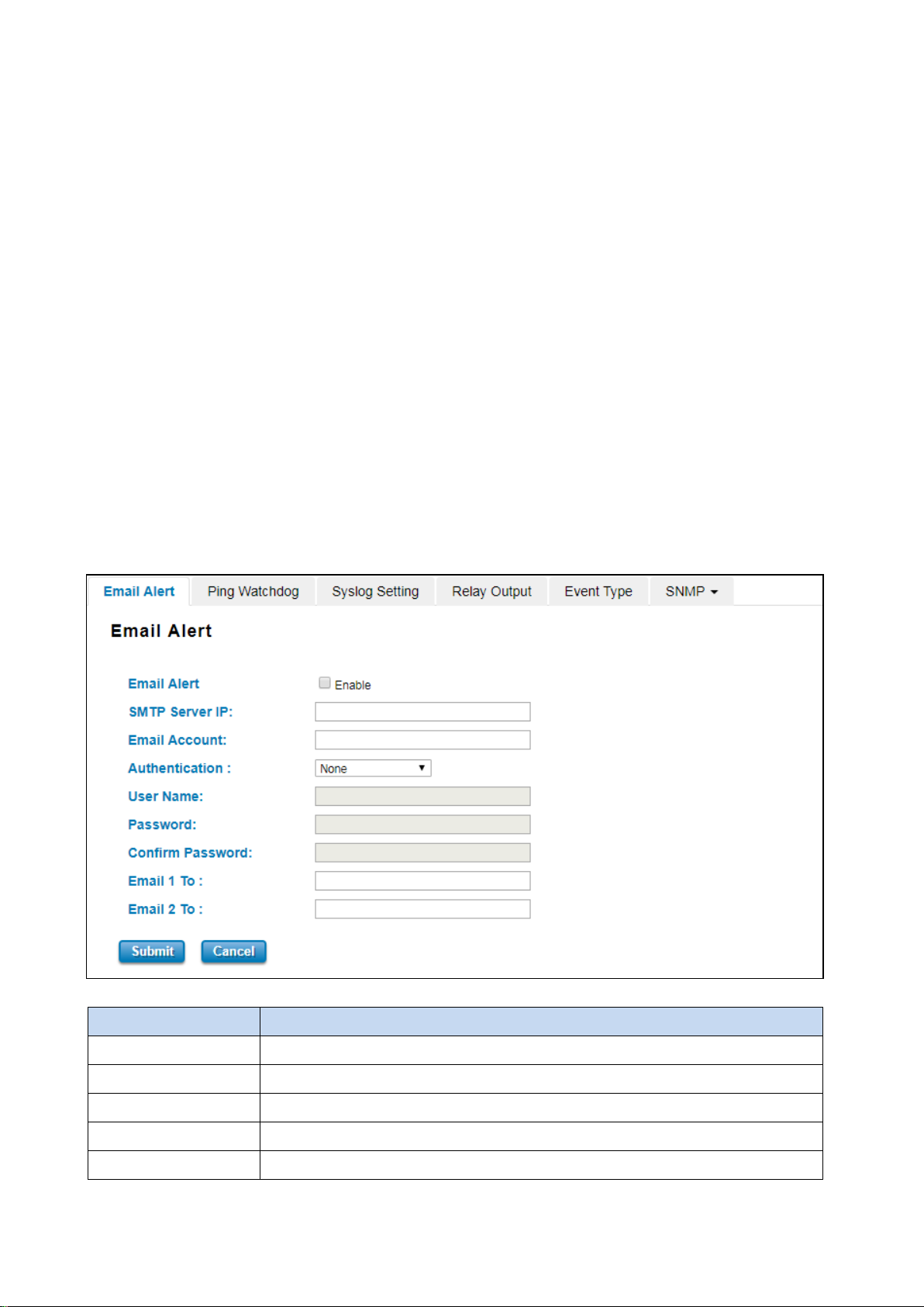
3.9.2 RIPv2
WoMaster Industrial Router is supported with RIPv2. The Routing Information Protocol (RIP) is a distance-vector,
interior gateway (IGP) routing protocol used by routers to exchange routing information. RIP uses the hop count as a
routing metric. RIP prevents routing loops by implementing a limit on the number of hops allowed in a path from the
source to a destination. The maximum number of hops allowed for RIP is 15. This hop limit, however, also limits the
size of networks that RIP can support. RIP version 2 (RIPv2) was developed due to the deficiencies of the original RIP.
3.10 WARNING
WoMaster’ router provides several types of Warning feature for remote monitoring of end devices status or network
changes.
3.10.1 EMAIL ALERT
WoMaster router supports E-mail Warning feature. With this function being enabled, the user is allowed to
configure the detail settings for sending the e-mail alert to the SMTP server when the events occur. This page allows
User to enable E-mail Alert, assign the SMTP Server IP, Sender E-mail, and Receiver E-mail. If the SMTP server
requests User to authorize first, User can also setup the username and password on this page.
The description of the columns is as below:
TERMS DESCRIPTION
Email Alert Check the to enable the function
SMTP Server IP Address Enter the IP address of the Email Server
Email Account Enter the Email Server Account
Authentication Choose the Authentication mode (None, Plain, Login)
User Name Enter email Account name (Max.40 characters)
92
Page 93
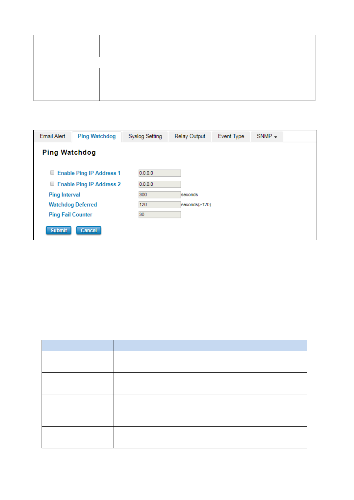
Set the second IP Address to check if
The device needs time to boot, the startup delay use to buffer to prevent the
Password Enter the password of the email account
Confirm Password Re-type the password of the email account
User can set up to 2 email addresses to receive email alarm from the router
Email 1 To The first email address to receive an email alert from the router (Max. 40 characters)
Email 2 To The second email address to receive an email alert from the router (Max. 40
characters)
Once User finishes configuring the settings, click on Submit to apply the User configuration.
3.10.2 PING WATCHDOG
Ping Watchdog is a feature that helps WoMaster’ router to allow user continuously ping a specific remote host for
connection status using a user-defined IP address (or an Internet gateway). In this section, WoMaster provides two
target IP Addresses, in order if the other IP Address cannot be reached, so there is another backup IP address. There
are two conditions in this Ping Watchdog section, the first one is when the device continuously ping the target IP and
in the end, it can reach one of the target IPs the device would not reboot. But if both targets IPs cannot be reached,
the device will start counting the Ping Fail Counter time till it can be reached. If it is unable to ping the target IP
address, this device will automatically reboot. After User finishes configuring the settings, click on Submit to apply
User configuration.
The description of the columns is as below:
TERMS DESCRIPTION
Enable Ping IP Address 1 Clicks enable to activate the feature. Set the first IP Address to check if the
device is alive or not
Enable Ping IP Address 2 Clicks enable to activate the feature.
the device is alive or not
Ping Interval Default: 300 (seconds)
Set the interval timer to Ping the remote device. Every 300 seconds the
device will try to ping the target IP.
Watchdog Deferred Default: 120 (seconds) >120
93
Page 94
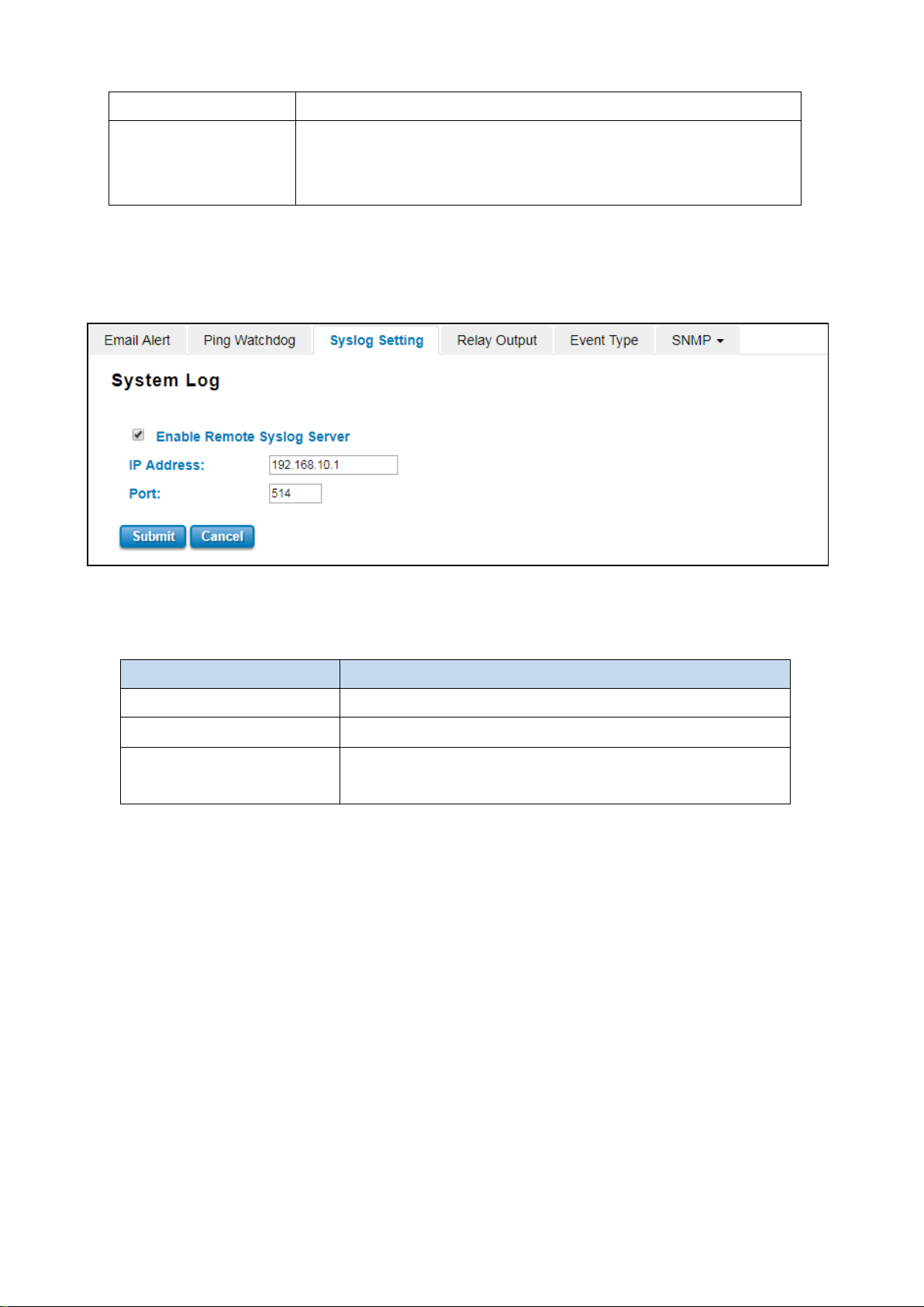
device continue to reboot itself.
Ping Fail Counter Default: 30
When the remaining Ping Fail Counter reach to 0 or reach the failure count,
the device will reboot.
Click Submit to apply the configuration.
3.10.3 SYSLOG SETTING
System Log is useful to provide system administrator locally or remotely monitor router events history.
Once User finishes configuring the settings, click on Submit to apply User configuration. User can monitor the system
logs in [Diagnostics] / [Event Log] page
The condition or term described as following table.
TERMS DESCRIPTION
Enable Remote Syslog Server Select Enable to enable system log
IP Address Specify the IP address of the server.
Port
After finish with the configuration, clicks Submit to activate the function.
Default: 514
Specify the port number of the server
94
Page 95
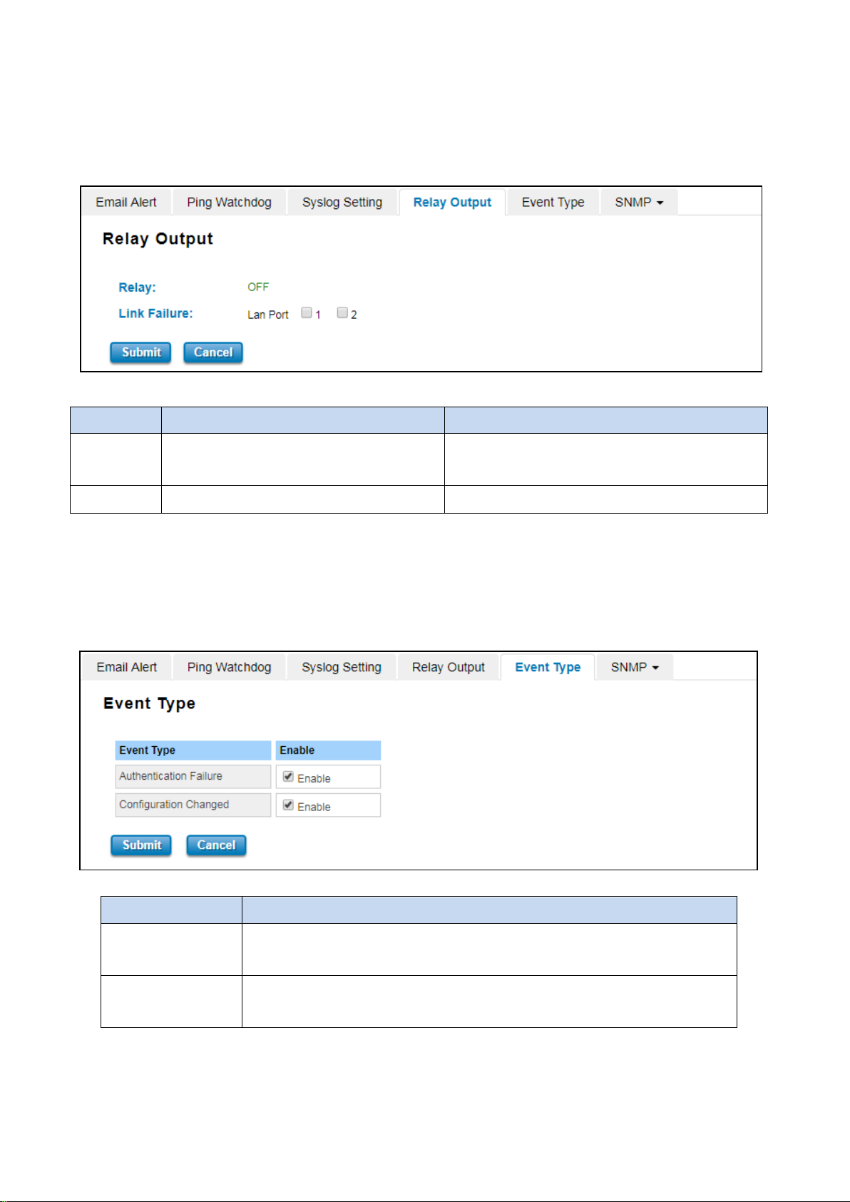
The status change to ON if any kind of failure is
3.10.4 RELAY OUTPUT
WoMaster’ router provides 1 alarm relay output, also known as Digital Output. These settings in Relay Output section
control the events that will trigger the alarm output. The Relay Output configuration interface has shown as below:
The condition or term described as following table.
TERMS CONDITION DESCRIPTION
Relay ON or OFF
Link Failure LAN Port number 1 and 2 Monitoring port link down event
After finishing the configuration, clicks Submit to activate the relay alarm function.
detected. OFF if the status is normal.
3.10.5 EVENT TYPE
In this page user allowed to select the Event Type Event Warning Type: The event warming type selection. It has two
event types, Authentication Failure and Configuration Changed.
TERMS DESCRIPTION
Authentication
Failure
Configuration
Changed
Click Submit to apply the configuration.
When the authentication fails, the system will issue the event log/email alert to
the system log/SMTP server respectively.
When there are any kinds of changing in the configuration, the system will issue
the event log/email alert to the system log/SMTP server respectively.
95
Page 96
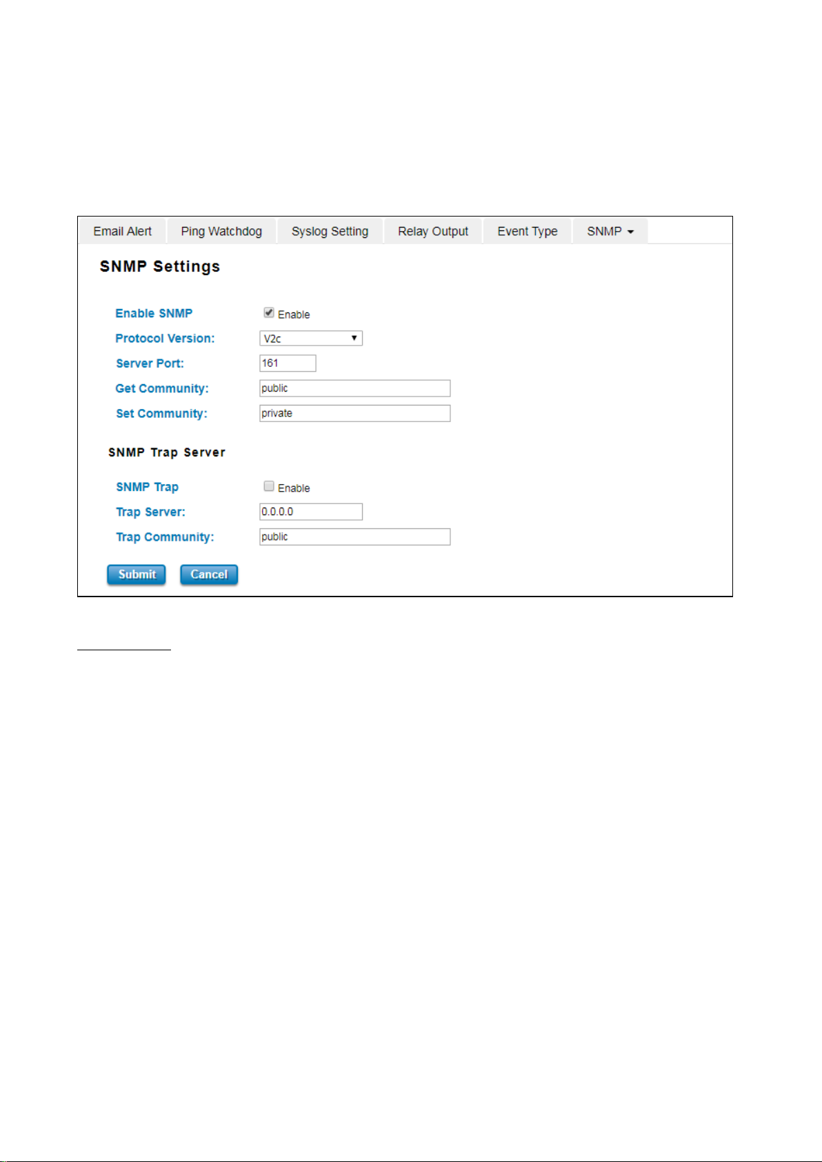
3.10.6 SNMP
SNMP is a standard TCP/IP protocol for network management. Network administrators use SNMP to monitor and
map network availability, performance, and error rates. System management software uses SNMP to allow
administrators to remotely monitor and manage thousands of systems on a network, often by presenting the data
gathered from monitored devices in a snapshot or dashboard view. WoMaster’ Router support SNMP V2c and V3
SNMP Setting
In this page, user may configure the SNMP setting, click enable to activate the function. Select the Protocol version
(V2c/V3), configure the server port, set up the password for the Get Community and specify the password for Set
Community.
SNMPv2C
SNMPv2c is a sub-version of SNMPv2. Its key advantage over previous versions is the Inform command. Unlike Traps,
which are simply received by a manager, Informs are positively acknowledged with a response message. If a
manager does not reply to an Inform, the SNMP agent will resend the Inform.
SNMP V3
SNMPv3 is the newest version of SNMP. Its primary feature is enhanced security.
SNMPv3 security comes primarily in 2 forms:
Authentication is used to ensure that traps are read by only the intended recipient.
Privacy encrypts the payload of the SNMP message to ensure that it cannot be read by unauthorized users.
96
Page 97
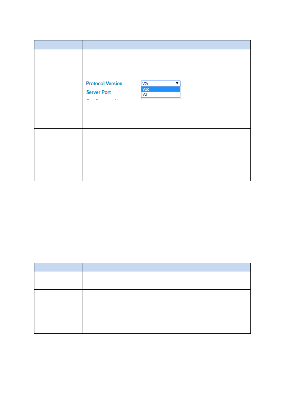
The description of the columns is as below:
TERMS DESCRIPTION
Enable SNMP Click the box to enable the SNMP function.
Default: V2c
Select the SNMP protocol version.
Protocol Version
Default: 161
Server Port
Get Community
Set Community
After finishing the configuration, clicks Submit to activate the function.
Sets the port on which SNMP data has been sent. User can specify port by marking
on user defined and specify port that user wants SNMP data to be sent.
Default: public
Create the name for a group or community of administrators who can view SNMP
data.
Default: private
Create the name for a group or community of administrators who can write or edit
SNMP data.
SNMP Trap Server
SNMP trap is the most frequently used SNMP messages. These messages are sent to the manager by an agent when
an issue needs to be reported. SNMP traps are quite unique if compared to other message types, since they are the
only method that can be directly initiated by an SNMP agent. The other types of messages are either initiated by the
SNMP manager or sent as a result of the manager’s request. This ability makes SNMP traps indispensable in most
networks. It is the most convenient way for an SNMP agent to inform the manager that something wrong is going on.
The description of the columns is as below:
TERMS DESCRIPTION
SNMP Trap
Trap Server
Trap Community
After finish with the configuration, clicks Submit to activate the function.
Clicks enable to activate the function. All of events that associated with the device
will be sent to the server in real time, and can be seen by remote clients
Default: 0.0.0.0
Set the IP Address of the trap server where to report the events.
Default: public
Create the name for a group or community of administrators who can allow
reporting the events. If the group is match then the events can be reported.
97
Page 98
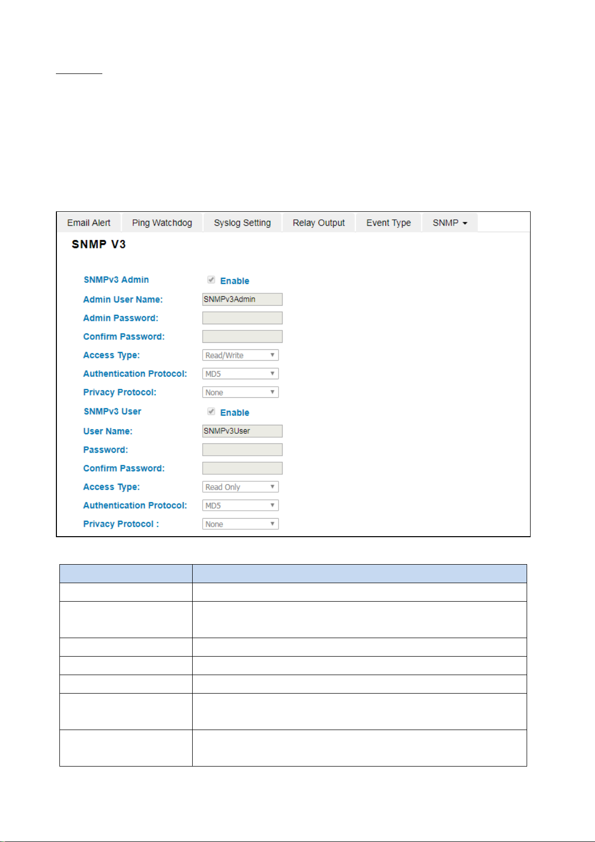
SNMP V3
SNMP v3 can provide more security functions when the user performs remote management through SNMP protocol.
This field displays the SNMPv3 configuration page for Admin and User. If the value from Access Type is set to Read-
Write, the SNMPv3 user will be able to set and retrieve parameters on the system. And if the value is set to Read
Only, the SNMPv3 user will only be able to retrieve parameter information. It delivers SNMP information to the
administrator with user authentication; all of data between the router and the administrator are encrypted to ensure
secure communication.
security. To activate the page make sure user has already chosen SNMPv3 at the SNMP Setting page.
SNMPv3 requires an authentication level of MD5 or DES to encrypt data to enhance data
TERMS DESCRIPTION
SNMPv3 Admin Clicks enable to activate the function and the entries for SNMPv3 Admin.
Admin User Name Default: SNMPv3Admin
Set up the User Name for the SNMPv3 Admin
Admin Password Set up the Password for the SNMPv3 Admin
Confirm Password Confirm the Admin for the SNMPv3 Admin
Access Type Access type for the SNMPv3 Admin, choose Read Only or Read and Write
Authentication Protocol Default: MD5
Provides authentication based on MD5 or SHA algorithms.
Privacy Protocol Specify the encryption method for SNMP communication. None and DES are
available.
98
Page 99

None: No encryption is applied.
DES: Data Encryption Standard, it applies a 58-bit key to each 64-bit block
of data.
SNMPv3 User Clicks enable to activate the function and the entries for SNMPv3 User
User Name Default: SNMPv3User
Set up the User Name for the SNMPv3 User
Password Set up the Password for the SNMPv3 User
Confirm Password Confirm the Admin for the SNMPv3 User
Access Type Access type for the SNMPv3 User, choose Read Only or Read and Write
Authentication Protocol Default: MD5
Provides authentication based on MD5 or SHA algorithms.
Privacy Protocol Specify the encryption method for SNMP communication. None and DES are
available.
None: No encryption is applied.
DES: Data Encryption Standard, it applies a 58-bit key to each 64-bit block
of data.
99
Page 100
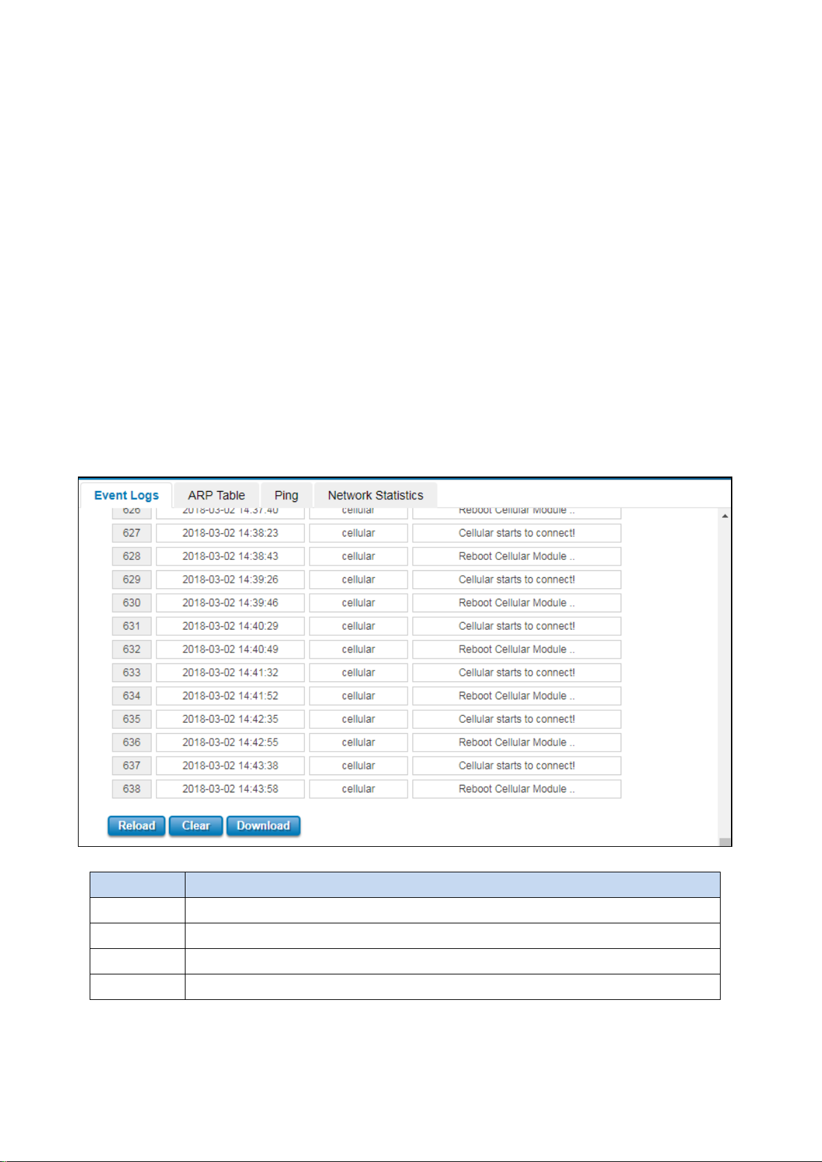
3.11 DIAGNOSTICS
WoMaster Router provides several types of features for User to monitor the status of the router or diagnostic for
User to check the problem when encountering problems related to the router.
Following commands are included in this group:
3.11.1 Event Logs
3.11.2 ARP Table
3.11.3 Ping
3.11.4 Traceroute
3.11.5 Network Statistic
3.11.6 Client Association List
3.11.1 EVENT LOGS
When remote System Log server mode is activated, the router will record occurred events in local log table. This
page shows this log table. The entry includes the index, occurred data, time and content of the events.
TERMS DESCRIPTION
# Event index assigned to identify the event sequence.
Time The time is updated based on how the current date and time is set in the Basic Setting page.
Source Show the log’s source.
Message Show the record status.
Click Reload to refresh the table. Click Clear to remove the entire event logs list. User may download the event logs
file by click Download.
100
 Loading...