


 Loading...
Olympus Processor
Cabling and Configuration Guide

ProVation® Medical Olympus Processor Cabling and Configuration Guide
NOTICE
© 1999-2013 ProVation Medical, Inc. a Wolters Kluwer Health Company. All rights reserved.
ProVation Medical, Inc. ("ProVation"), a Wolters Kluwer Company, reserves the right to make improvements to the software product described in this manual at any time without notice.
ProVation is the copyright owner of its software products, including the entire content of this manual, diskettes and CD ROMs supplied. This document may not, in whole or in part, be copied, photocopied, reproduced, translated, modified, distributed, displayed or reduced to any electronic medium or machinereadable form without prior consent from ProVation. Willful violation of the Copyright Law of the United States of America can result in civil and criminal penalties.
The information contained in this document is confidential to properly licensed users of ProVation. Willful violation can result in civil and criminal penalties.
ProVation®, Anticipatory Interface®, and Clinical Productivity by Design® are registered trademarks of ProVation in the United States registered on July 23, 2002, July 22, 2003, and April 1, 2003 respectively. All other brand, product or company names are trademarks of their respective owners.
Indications for use:
ProVation MD™ and ProVation MultiCaregiver™ applications are intended for use in the following situations:
▪Create procedure documentation
▪Code for supplies and medications used
▪Report on procedure documentation and other administrative functions
The resulting documentation and associated images are to be used for the purpose of patient education and reference. The information and images are not to be used for diagnostic purposes.
Precautions:
ProVation MD™ and ProVation MultiCaregiver™ applications should be used as designed and documented in their respective user and configuration manuals.
Caution:
United States Federal Law restricts this device to sale by or on the order of a physician (or properly licensed practitioner).
ProVation Medical Inc.
800 Washington Avenue North Suite 400
Minneapolis, MN 55401 888 -9 52 -66 73
www.provationmedical.com
All information about individuals and cases contained within this documentation is hypothetical and provided for example only and does not relate to any actual case or individual. This information is offered by way of illustration and example only.
Revision Date: 12/18/2013
Cabling Guide Olympus 07 |
Page 2 of 68 |

ProVation® Medical Olympus Processor Cabling and Configuration Guide
OLYMPUS CV-100 ............................................................................................... |
4 |
Olympus CV-100 Cables..................................................................................................................... |
4 |
Olympus CV-100 Cabling Diagrams ................................................................................................. |
5 |
Olympus CV-100 Pictures.................................................................................................................. |
6 |
Olympus CV-100 Cabling and Configuration setup ...................................................................... |
7 |
OLYMPUS CV-140 ............................................................................................... |
9 |
Olympus CV-140 Cables..................................................................................................................... |
9 |
Olympus CV-140 Cabling Diagrams ................................................................................................ |
10 |
Olympus CV-140 Pictures................................................................................................................. |
11 |
Olympus CV-140 Cabling and Configuration setup ..................................................................... |
13 |
OLYMPUS CV-160 ............................................................................................. |
15 |
Olympus CV-160 Cables.................................................................................................................... |
15 |
Olympus CV-160 Cabling Diagrams ................................................................................................ |
16 |
Olympus CV-160 Pictures................................................................................................................. |
17 |
Olympus CV-160 Cabling and Configuration setup ..................................................................... |
20 |
OLYMPUS CV-180 ............................................................................................. |
22 |
Olympus CV-180 Cables.................................................................................................................... |
22 |
Olympus CV-180 Cabling Diagrams ................................................................................................ |
23 |
Olympus CV-180 Pictures................................................................................................................. |
24 |
Olympus CV-180 Cabling and Configuration setup ..................................................................... |
28 |
OLYMPUS CV-190 ............................................................................................. |
30 |
Olympus CV-190 Cables.................................................................................................................... |
30 |
Olympus CV-190 Cabling Diagrams ................................................................................................ |
32 |
Olympus CV-190 Pictures................................................................................................................. |
33 |
Olympus CV-190 Cabling and Configuration setup ..................................................................... |
36 |
OLYMPUS CV-180 FOR HD IMAGES ............................................................................ |
39 |
Olympus CV-180 Cables for HD Images ......................................................................................... |
39 |
Olympus CV-180 Cabling Diagrams for HD Images ...................................................................... |
40 |
Olympus CV-180 Pictures for HD Images....................................................................................... |
42 |
Olympus CV-180 Cabling and Configuration for HD Images setup ........................................... |
46 |
OLYMPUS CV-190 FOR HD IMAGES ............................................................................ |
48 |
Olympus CV-190 Cables for HD Images ......................................................................................... |
48 |
Olympus CV-190 Cabling Diagrams for HD Images ...................................................................... |
50 |
Olympus CV-190 Pictures for HD Images....................................................................................... |
52 |
Olympus CV-190 Cabling and Configuration for HD images setup ........................................... |
55 |
PICTURE IN PICTURE SUPPORT ................................................................................. |
57 |
Olympus CV-180 Picture In Picture Connection Options............................................................ |
57 |
Olympus CV-190 Picture in Picture Connection Options............................................................ |
60 |
CABLING DIAGRAMS FOR SWITCHBOX CONFIGURATIONS......................................................... |
63 |
Olympus Processor with switchbox configuration for dPict cards ........................................... |
64 |
CABLING RECOMMENDATIONS FOR BEHIND THE WALL CABLING ................................................. |
65 |
Cabling Guide Olympus 07 |
Page 3 of 68 |

ProVation® Medical Olympus Processor Cabling and Configuration Guide
Olympus CV-100
Olympus CV-100 Cables
The Olympus CV-100 Processor requires 2 cables that are proprietary to Olympus.
1.Photo Cable (for RGB images, connects to video card in computer running ProVation MD)
2.Remote Digital File Cable (for image capture signal, connects to serial port on computer running ProVation MD)
Each cable comes in varying lengths, and may be extended with other nonproprietary cables. Below is a list of the Olympus part numbers and lengths of each cable. Also listed are the extension cables needed, which are purchased from Black Box Corporation, a cable manufacturer. Barrel connectors are used to connect two BNC cables together.
Olympus Photo Cable (Live video)
• |
55592L4 |
length of 4’ |
• |
55592L6 |
length of 6’ |
• |
55592L25 |
length of 25’ |
Olympus Remote Digital File Cable (capture signal)
• |
55597L6 |
length of 6’ |
• |
55597L10 |
length of 10’ |
• |
55597L25 |
length of 25’ |
Extension cables for Photo Cable (Part numbers from Black Box Corporation)
• |
EYNRGBS2-0010-MM |
length of 10’ |
• |
EYNRGBS2-0025-MM |
length of 25’ |
• |
EYNRGBS2-0050-MM |
length of 50’ |
• |
Custom cable |
length over 50’ |
Extension cables for Remote Digital File Cable (Part numbers from Black Box Corporation)
• |
EDN12H-0005-MF |
length of 5’ |
• |
EDN12H-0010-MF |
length of 10’ |
• |
EDN12H-0025-MF |
length of 25’ |
• |
EDN12H-0050-MF |
length of 50’ |
• |
Custom cable |
length over 50’ |
Cabling Guide Olympus 07 |
Page 4 of 68 |
ProVation® Medical Olympus Processor Cabling and Configuration Guide
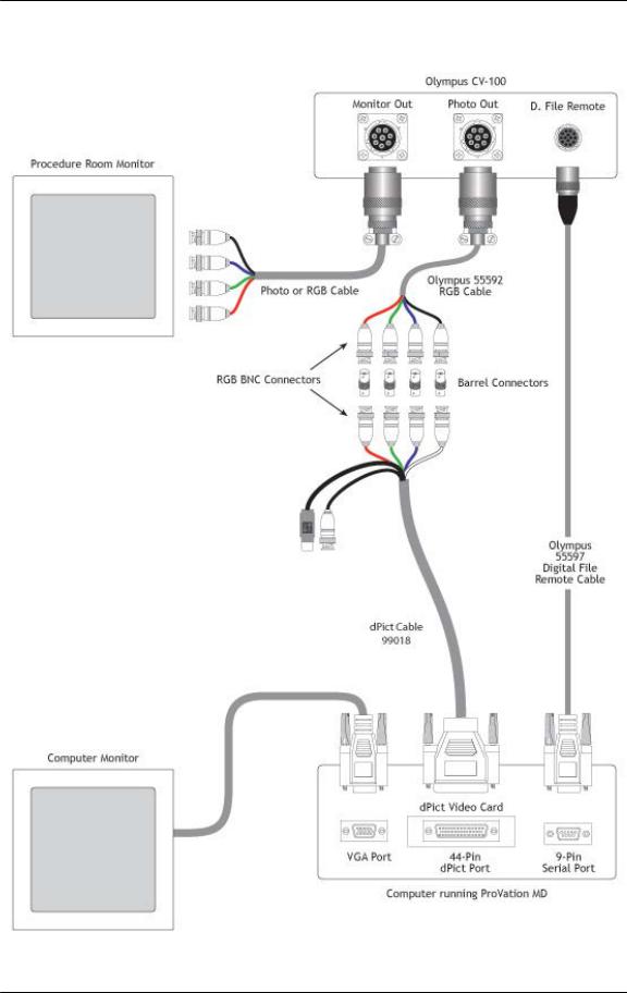
Olympus CV-100 Cabling Diagrams
Olympus CV-100 with dPict Cabling
Cabling Guide Olympus 07 |
Page 5 of 68 |
ProVation® Medical Olympus Processor Cabling and Configuration Guide
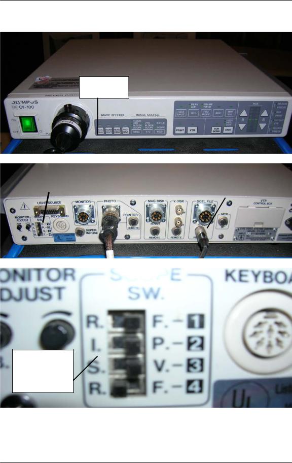
Olympus CV-100 Pictures
DGTL File
Button
Dip |
|
Video |
|
|
|
|
Digital File |
||||
Switches |
|
Out Port |
|
||
|
|
Out Port |
|||
|
|
|
|
|
|
|
|
|
|
|
|
|
|
|
|
|
|
Switches to set up what the buttons on the scope do
Cabling Guide Olympus 07 |
Page 6 of 68 |

ProVation® Medical Olympus Processor Cabling and Configuration Guide
Olympus CV-100 Cabling and Configuration setup
To connect an Olympus CV-100 processor to a computer, each processor will need the following:
1.) Olympus CV-100 Processor
- **NOTE** CV-100 processors having serial numbers starting with 70, 71, 72, 73, or 79 may have problems capturing images due to a problem with the chipset in the CV-100 processor
2.) Olympus Photo Cable
3.) Olympus Digital File Cable
4.) Barrel Connectors (one for each of the RGBS cables – typically 4 per setup)
5.) Image capture card
6.) Image capture card cable(s)
To the cabling, follow the below steps: 1.) Connect the Photo cable:
a.Connect the Olympus Photo cable to the port labeled Photo Out on the back of the Olympus Processor. **NOTE** If the site is currently using a Mavigraph the photo cable going to the Mavigraph may already be using the photo out port. This cable can be unplugged when hooking up a ProVation MD image capture computer.
b.The photo cable ends with 4 RGBS BNC connections. Connect a barrel connector to each of the RGBS BNC connectors at the end of the Olympus Photo cable.
c.Connect the other end of the barrel connector to the image capture card cable (See diagram above for more detail).
d.Plug the image capture card cable into the image capture card on the computer.
2.) Connect the digital file cable into the digital file remote port on the back of the processor. This cable ends with a female 9 pin connector, which should be plugged into the serial port on the back of the ProVation MD image capture computer.
3.) Ensure that on the front of the processor that the DGTL File light is lit up (this button is located in the lower left of the Olympus Processor near where the scope cable plugs into the processor).
4.) On the back of the processor there are 4 dip switches located near the far left side of the processor. Make sure that either 1 or 4 is set to ‘R’ for Release.
Cabling Guide Olympus 07 |
Page 7 of 68 |

ProVation® Medical Olympus Processor Cabling and Configuration Guide
5.) In ProVation MD, set the following settings to enable image capture mode:
a.Set Capturecard = True
b.Set Cardname = The image capture card you are using
c.Set Computername = A unique name for the room you are in (I.E. ROOM1) –
**Note** This name should be in all caps and should not have any spaces in the name.
d.Set manufacturer to Olympus in the configuration settings screen for the ProVation MD image capture computer.
Cabling Guide Olympus 07 |
Page 8 of 68 |

ProVation® Medical Olympus Processor Cabling and Configuration Guide
Olympus CV-140
Olympus CV-140 Cables
The Olympus CV-140 Processor requires 2 cables that are proprietary to Olympus.
1.Photo Cable (for RGB images, connects to video card in computer running ProVation MD. Same photo cable as CV 100)
2.Remote Digital File Cable (for image capture signal, connects to serial port in computer running ProVation MD)
Each cable comes in varying lengths, and may be extended with other nonproprietary cables. Below is a list of the Olympus part numbers and lengths of each cable. Also listed are the extension cables needed, which are purchased from Black Box Corporation, a cable manufacturer. Barrel connectors are used to connect two BNC cables together.
Olympus Photo Cable (Live video)
• |
55592L4 |
length of 4’ |
• |
55592L6 |
length of 6’ |
• |
5559L25 |
length of 25’ |
Olympus Remote Digital File Cable (Capture signal)
• |
55645L6-1 |
length of 6’ |
• |
55645L10-1 |
length of 10’ |
• |
55645L25-1 |
length of 25’ |
Extension cables for Photo Cable (Part numbers from Black Box Corporation)
• |
EYNRGBS2-0010-MM |
length of 10’ |
• |
EYNRGBS2-0025-MM |
length of 25’ |
• |
EYNRGBS2-0050-MM |
length of 50’ |
• |
Custom cable |
length over 50’ |
Extension cables for Remote Digital File Cable (Part numbers from Black Box Corporation)
• |
EDN12H-0005-MF |
length of 5’ |
• |
EDN12H-0010-MF |
length of 10’ |
• |
EDN12H-0025-MF |
length of 25’ |
• |
EDN12H-0050-MF |
length of 50’ |
• |
Custom cable |
length over 50’ |
Cabling Guide Olympus 07 |
Page 9 of 68 |
ProVation® Medical Olympus Processor Cabling and Configuration Guide
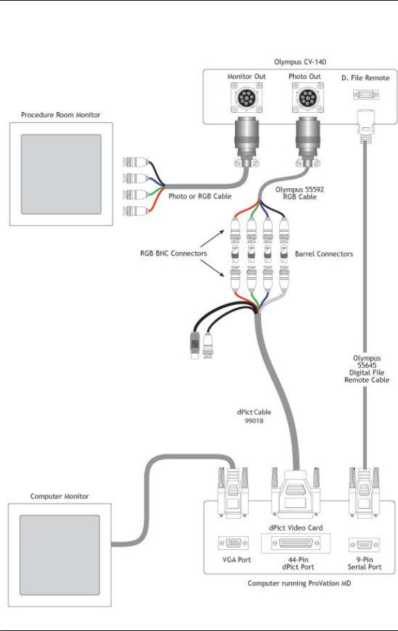
Olympus CV-140 Cabling Diagrams
Olympus CV-140 with dPict Cabling
Cabling Guide Olympus 07 |
Page 10 of 68 |
ProVation® Medical Olympus Processor Cabling and Configuration Guide
Olympus CV-140 Pictures
Digital File
Out Port
Video Out
Port
System
Setup Key
Cabling Guide Olympus 07 |
Page 11 of 68 |
ProVation® Medical Olympus Processor Cabling and Configuration Guide
Cabling Guide Olympus 07 |
Page 12 of 68 |

ProVation® Medical Olympus Processor Cabling and Configuration Guide
Olympus CV-140 Cabling and Configuration setup
To connect an Olympus CV-140 processor to a computer, each processor will need the following:
1.) Olympus CV-140 Processor
2.) Olympus Photo Cable
3.) Olympus Digital File Cable
4.) Barrel Connectors (one for each of the RGBS cables – typically 4 per setup)
5.) Image capture card
6.) Image capture card cable(s)
To connect the cabling, follow the below steps: 1.) Connect the photo cable:
a.Connect the Olympus Photo cable to the port labeled Photo Out on the back of the Olympus Processor.
b.The photo cable ends with 4 RGBS BNC connections. Connect a barrel connector to each of the RGBS BNC connectors at the end of the Olympus Photo cable.
c.Connect the other end of the barrel connector to the image capture card cable (See diagram above for more detail).
d.Plug the image capture card cable into the image capture card on
the computer.
2.) Connect the digital file cable into the digital file remote port on the back of the processor. This cable ends with a female 9 pin connector, which should be plugged into the serial port on the back of the ProVation MD image capture computer.
3.) Change the settings on the Olympus Processor:
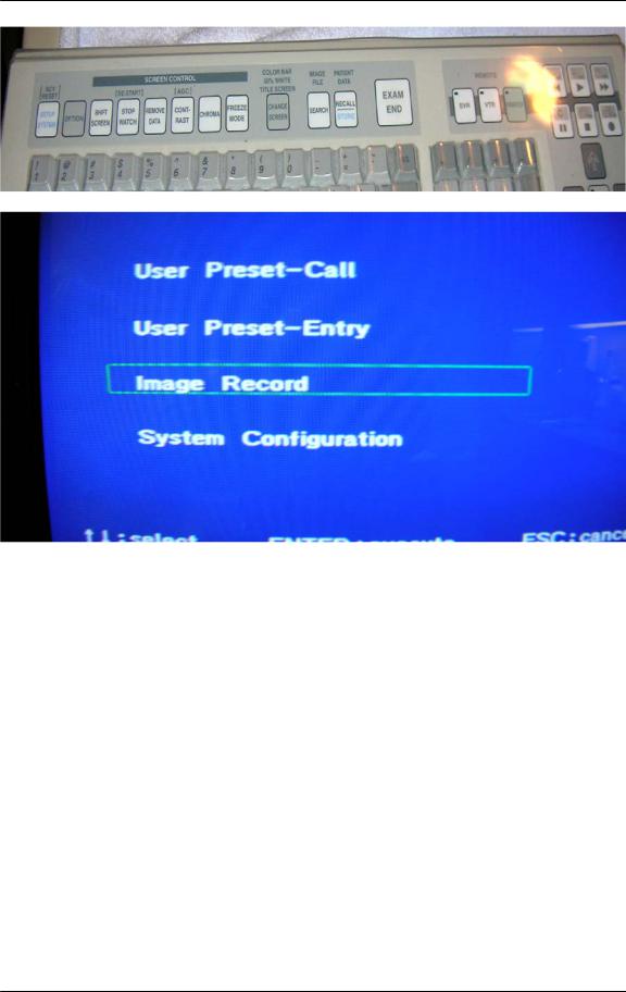
a.Using the Olympus CV-140 Keyboard and looking at the clinical monitor (not the computer screen) press the system setup key on the keyboard (top left button).
b.On the first screen use the arrow keys on the Olympus keyboard to scroll down to Image Record, and hit the enter key.
c.On the next screen scroll down to D.F. Record and set it to On using the side arrow keys.
d.Then press the Enter key.
e.At the prompt that reads, “Are you sure? Y/N”, press Y.
f.Hit the Esc Key to exit out of the system setup screen.
4.) Set up the Scope Buttons to capture:
a.You will also want to ensure that at least one of the scope buttons is set to Release. (The release setting is what actually triggers the computer to capture images.): With the CV-140 keyboard plugged into the CV-140 video processor, while viewing the clinical monitor (not the computer monitor) press the Setup System key.
b.Using the arrow keys, place the green box around User Preset Entry and press Enter.
Cabling Guide Olympus 07 |
Page 13 of 68 |

ProVation® Medical Olympus Processor Cabling and Configuration Guide
c.Arrow down to the first choice (which usually will have some doctor’s name, default, or no data next to 1.), press Enter.
d.Arrow down to the appropriate endoscope button (the clinic’s preference for picture taking is usually either #1 or #4).
e.Use the side arrow keys to choose Release.
f.Press Enter.
g.At the prompt that reads, “Are you sure? Y/N”, press Y.
h.Press Esc to return to the normal viewing screen.
5.) In ProVation MD, set the following settings to enable image capture mode:
a.Set Capturecard = True
b.Set Cardname = The image capture card you are using
c.Set Computername = A unique name for the room you are in (I.E. ROOM1) –
**Note** This name should be in all caps and should not have any spaces in the name.
d.Set manufacturer to Olympus in the configuration settings screen for the ProVation MD image capture computer.
Cabling Guide Olympus 07 |
Page 14 of 68 |

ProVation® Medical Olympus Processor Cabling and Configuration Guide
Olympus CV-160
Olympus CV-160 Cables
The Olympus CV-160 Processor requires 2 cables that are proprietary to Olympus.
1.Photo Cable (for RGB images, connects to video card in computer running ProVation MD)
2.Remote Digital File Cable (for image capture signal, connects to serial port in computer running ProVation MD)
Each cable comes in varying lengths, and may be extended with other nonproprietary cables. Below is a list of the Olympus part numbers and lengths of each cable. Also listed are the extension cables needed, which are purchased from Black Box Corporation, a cable manufacturer. Barrel connectors are used to connect two BNC cables together.
Olympus Photo Cable (Live video)
• MH984 length of 6’
Olympus Remote Digital File Cable (Capture signal)
• |
55645L6-1 |
length of 6’ |
• |
55645L10-1 |
length of 10’ |
• |
55645L25-1 |
length of 25’ |
Extension cables for Photo Cable (Part numbers from Black Box Corporation)
• |
EYNRGBS2-0010-MM |
length of 10’ |
• |
EYNRGBS2-0025-MM |
length of 25’ |
• |
EYNRGBS2-0050-MM |
length of 50’ |
• |
Custom cable |
length over 50’ |
Extension cables for Remote Digital File Cable (Part numbers from Black Box Corporation)
• |
EDN12H-0005-MF |
length of 5’ |
• |
EDN12H-0010-MF |
length of 10’ |
• |
EDN12H-0025-MF |
length of 25’ |
• |
EDN12H-0050-MF |
length of 50’ |
• |
Custom cable |
length over 50’ |
Optional ‘Y’ cable needed for sites using a Flush pump (splits digital file cable to allow two connections – Purchased from Olympus
•IS40088
Cabling Guide Olympus 07 |
Page 15 of 68 |
ProVation® Medical Olympus Processor Cabling and Configuration Guide
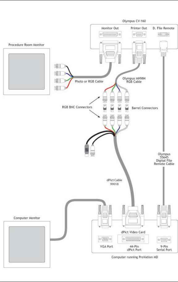
Olympus CV-160 Cabling Diagrams
Olympus CV-160 with dPict Cabling
Cabling Guide Olympus 07 |
Page 16 of 68 |

ProVation® Medical Olympus Processor Cabling and Configuration Guide
Olympus CV-160 Pictures
Video Out |
|
Digital File |
Port |
|
Out Port |
|
|
|
Cabling Guide Olympus 07 |
Page 17 of 68 |
ProVation® Medical Olympus Processor Cabling and Configuration Guide
System
Setup Key
Cabling Guide Olympus 07 |
Page 18 of 68 |
ProVation® Medical Olympus Processor Cabling and Configuration Guide
Cabling Guide Olympus 07 |
Page 19 of 68 |

ProVation® Medical Olympus Processor Cabling and Configuration Guide
Olympus CV-160 Cabling and Configuration setup
To connect an Olympus CV-160 processor to a computer, each processor will need the following:
1.) Olympus CV-160 Processor
2.) Olympus Photo Cable
3.) Olympus Digital File Cable
4.) Barrel Connectors (one for each of the RGBS cables – typically 4 per setup)
5.) Image capture card
6.) Image capture card cable(s)
To connect the cabling, follow the below steps: 1.) Connect the Photo Cable:
a.Connect the Olympus Photo cable to the port labeled Printer Out on the back of the Olympus Processor.
b.The photo cable ends with 4 RGBS BNC connections. Connect a barrel connector to each of the RGBS BNC connectors at the end
of the Olympus Photo cable.
**NOTE** The Sync cable in the Olympus cable is white in color, so you should make sure that white goes to the black cable on most image capture cables. The dPict sync cable is white in color.
c.Connect the other end of the barrel connector to the image capture card cable (See diagram above for more detail).
d.Plug the image capture card cable into the image capture card on the computer.
2.) Connect the digital file cable into the digital file remote port on the back of the processor. This cable ends with a female 9 pin connector, which should be plugged into the serial port on the back of the ProVation MD image capture computer.
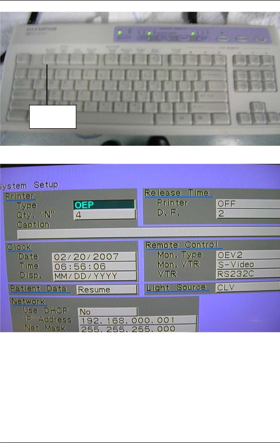
3.) Change the settings in the Olympus Processor:
a.Using the Olympus CV-160 Keyboard and looking at the clinical monitor (not the computer screen) press the system setup key on the keyboard (top left button).
b.On the screen that appears use the arrow keys on the Olympus keyboard set the printer type to FootSW.
c.Then use the arrow keys to get to the Release Time box.
d.Set the printer option to OFF.
e.Set the D.F. option to anything except OFF (usually set to .5).
f.Press the Enter key.
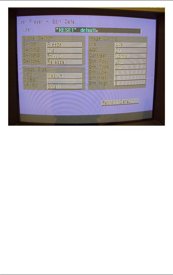
4.) Set up the Scope Buttons to Capture:
a.You will also want to ensure that at least one of the scope buttons is set to Release. (The release setting is what actually triggers the computer to capture images.): With the CV-160 keyboard plugged into the CV-160 video processor, while viewing the clinical monitor (not the computer monitor) press the User Preset key.
Cabling Guide Olympus 07 |
Page 20 of 68 |
ProVation® Medical Olympus Processor Cabling and Configuration Guide
b.Using the arrow keys, place the green box around User Preset Entry
c.Press Enter.
d.Highlight the sites entry (usually the first one) and choose to edit the configuration.
e.Arrow down to the appropriate endoscope button (the clinic’s preference for picture taking is usually either #1 or #4).
f.Use the side arrow keys to choose Release.
g.Press Enter.
h.At the prompt that reads, “Are you sure? Y/N”, press Y.
i.Press Esc to return to the normal viewing screen.
5.) In ProVation MD, set the following settings to enable image capture mode:
a.Set Capturecard = True
b.Set Cardname = The image capture card you are using
c.Set Computername = A unique name for the room you are in (I.E. ROOM1) –
**Note** This name should be in all caps and should not have any spaces in the name.
d.Set manufacturer to Olympus in the configuration settings screen for the ProVation MD image capture computer.
Cabling Guide Olympus 07 |
Page 21 of 68 |
Loading...