

Wolf Garten Robo Scooter 1800, Robo Scooter 3000 Operating Instructions Manual
Original operating instructions - en 2
Robo Scooter® 1800
Robo Scooter® 3000

Safety advise
I
Introduction
CE approved. All rights reserved.
Product, product specifications and this document are subject to change without notice.
All other trademarks are property of their respective owners.
Thank you for purchasing our product. We know that you will enjoy the extra free time you will have while using the unit to mow your
lawn. When set up and used properly, the unit will operate safely on your lawn and provide you with a quality of cut matched by a few
mowers of any kind. You will be impressed with your lawn’s appearance and best of all, the unit did it for you.
IMPORTANT!
The following pages contain important safety and operating instructions. Please read and follow all instructions in this
manual. Carefully read and review all safety instructions, warnings and cautions contained in this manual. Failure to
read and follow these instructions, warnings and cautionary statements may result in severe injury or death to persons
and pets or damage to personal property.
3
en
II
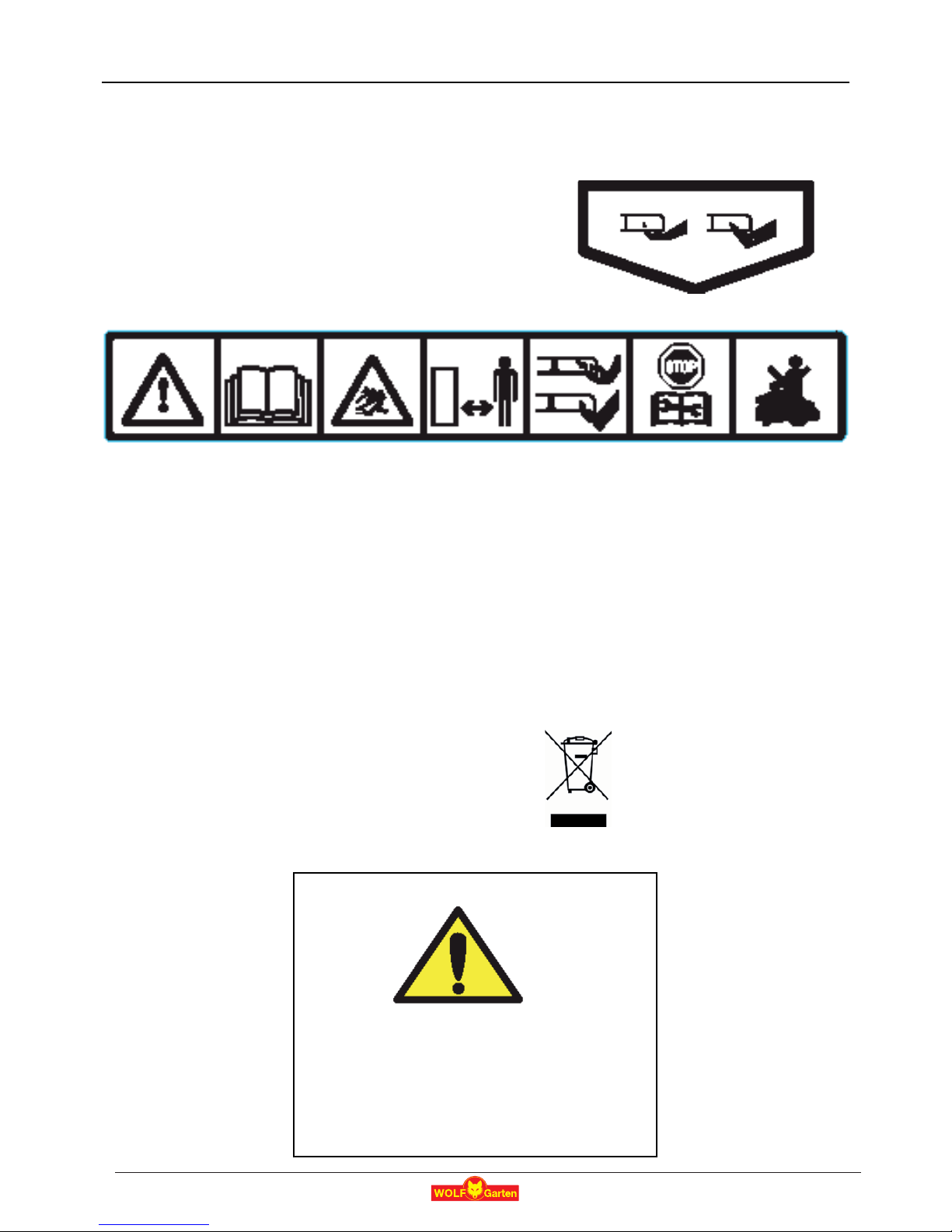
Warning Decal Definitions
These are the symbols on the unit; Read them carefully before operating.
DANGER! Sharp rotating blades. Keep hands and feet away.
Serious injury can occur. Caution – Do not touch rotating blade(s)
1. Safety alerts symbol – WARNING – This is a dangerous power tool.
Use care when operating and follow all safety instructions and warnings.
2. Read Operating & Safety Manual – Read user instructions before operating your unit.
3. Hazard of thrown or flying objects – Whole body exposure. Take caution.
4. Keep a safe distance from the unit when operating.
Keep people in particular children, pets and bystanders away from the area in which unit is being used.
5. Severing of toes or fingers – Rotary mower blade. Risk of injury from rotating cutting blade.
Keep hands and feet away and do not attempt to lift the unit from this area.
6. Operate the disabling device before working on or lifting the unit.
7. Do not ride on the unit.
Do not dispose the unit or any other part of it as unsorted
municipal waste – it should be collected separately.
1 2 3 4 5 6 7
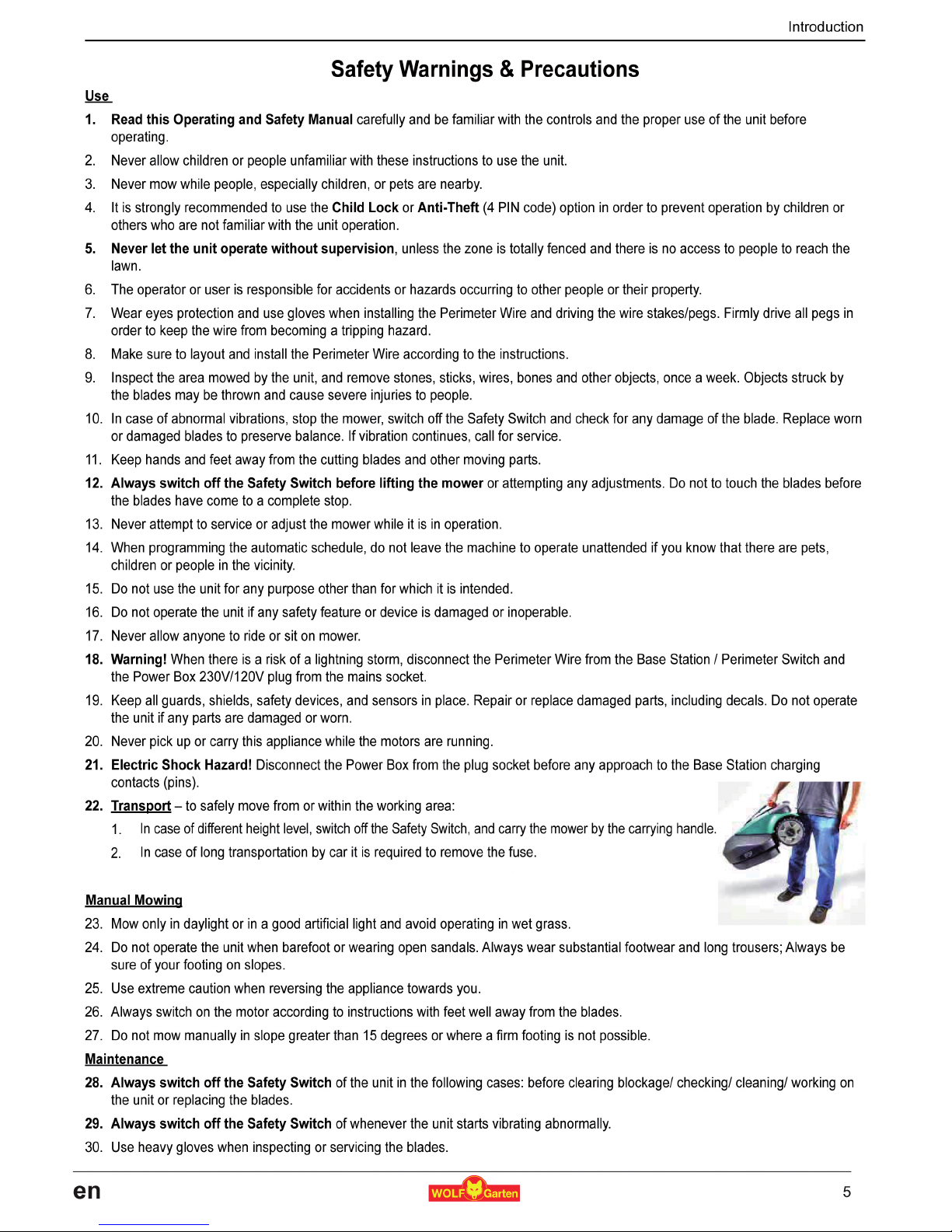
WARNING!
This warning symbol will be found at several
points throughout the pages of this manual.
It is intended to highlight an important safety,
warning or cautionary message.
Please pay particular attention to these
areas and be sure you fully understand
the message before proceeding.
4
en

Introduction
IV
31. Replace worn or damaged parts for safety.
32. Use only the original equipment and accessories. It is not permitted to modify the original design of the unit. All modifications are
made at your own risk.
33. Maintenance/ Servicing of the unit should be according to manufacturer instructions.
34. The Battery Pack contains electrolytes. In case of an electrolyte leakage from the battery pack, the actions described below are
required:
- Skin contact: Wash the contact areas off immediately with plenty of water and soap.
- Eye contact: Flush the eyes with plenty of clean water for at least 15 minutes immediately, without rubbing.
- Get medical treatment.
35. Ensure that the battery pack is charged using the correct charger recommended by the manufacturer. Incorrect use may result in
electric shock, overheating or leakage of corrosive liquid from the battery.
Product End of Use
36. The unit and its accessories should be collected separately at the end of their life to prevent waste electrical and electronic
equipment from ending up in landfill sites, to promote the reuse, treatment and recovery of electrical and electronic equipment
in purpose to preserve, protect and improve the quality of the environment, protect human health and utilize natural resources
prudently and rationally.
37. Do not dispose the unit or any other part of it (including the Power Box, Base Station and Perimeter Switch) as unsorted municipal
waste – it should be collected separately.
38. Ask your local distributor/dealer about return and collection systems available.
39. Do not dispose of the battery pack in a fire and do not place used batteries in your household trash.
The battery must be collected, recycled, or disposed of in an environmentally sound manner.
Safety Features
1. Child Lock / Safety Guard
This menu option offers a safety feature to help prevent children or others not familiar with the safe operation of the mower to
operate it freely.
2. Anti-Theft / Safety Guard
The Anti-Theft system provides the user a disabling function that will prevent anyone from using or driving the unit unless they
have the valid code to enter. You will be prompted to enter a four digit code of your choice to use as your personal security code.
3. Lift Sensor
In the event the mower is raised from its resting position on the ground during blade operation, the blades will stop rotating
immediately.
4. Tilt Sensor
In case the mower is lifted up towards a vertically position, the blade will stop immediately and the unit will warn about it.
5. Sensor Equipped Bumpers
The bumper is equipped with sensor activates when the mower strikes a solid, fixed object. When the bumper sensor is activated,
the mower will stop the rotation of the blades immediately, will stop movement in that direction and reverse itself away from the
obstacle.
6. Emergency Stop Button
The STOP button is located on the Carrying Handle. Pressing this button or lifting the handle at any time during operation will stop
all mower movement and the rotation of the blades immediately.
7. Safety Switch
Located below the bumper door, on the right side of the unit (when standing behind the mower). Switching off the Safety Switch will
prevent any operation of the the unit. It is required to switch it off before lifting the unit and before any maintenance is done.
8. Main Fuse
It is located at the rear side of the unit. Removing the Main Fuse will prevent any operation of the unit. It is required to remove the
fuse before transportation for long distance and before any service (parts replacement) is done.
9. Sealed Batteries
The batteries that operate the unit are completely sealed and will not leak any type of fluids, regardless of position.
10. Base Station / Perimeter Switch and Perimeter Wire
The unit cannot operate without a Perimeter Wire installed and activated through the Base Station / Perimeter Switch. In the event
the Perimeter Switch is turned off or otherwise fails to function, the unit will stop operating.
6
en
V
Introduction
How the Unit Works for You
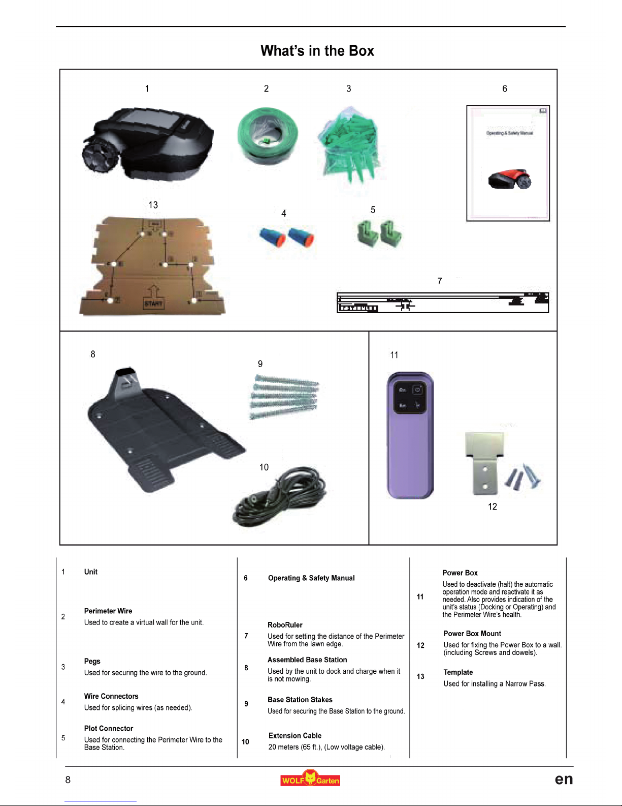
Perform a One-Time Setup before operating the unit for the first time.
[Detailed instructions are in the following chapters]
You will install a wire around the entire lawn and around protected areas within the
lawn area. This wire is the Perimeter Wire; it sets the boundaries for the unit.
Small pegs are supplied with the unit. You use them to fasten the Perimeter Wire into
the ground, below grass level.
The Perimeter Wire will gradually disappear under the growth of new grass until, quite
soon, it will be invisible.
You will place a Base Station and a Power Box along the Perimeter Wire. They
perform two basic functions:
o They generate a very low voltage signal along the Perimeter Wire.
o They charge the unit’s batteries.
After having completed the installation of the Perimeter Wire, Base Station, and the
Power Box, and performing the One-Time Setup, the unit will do all the mowing for you
for the entire season !
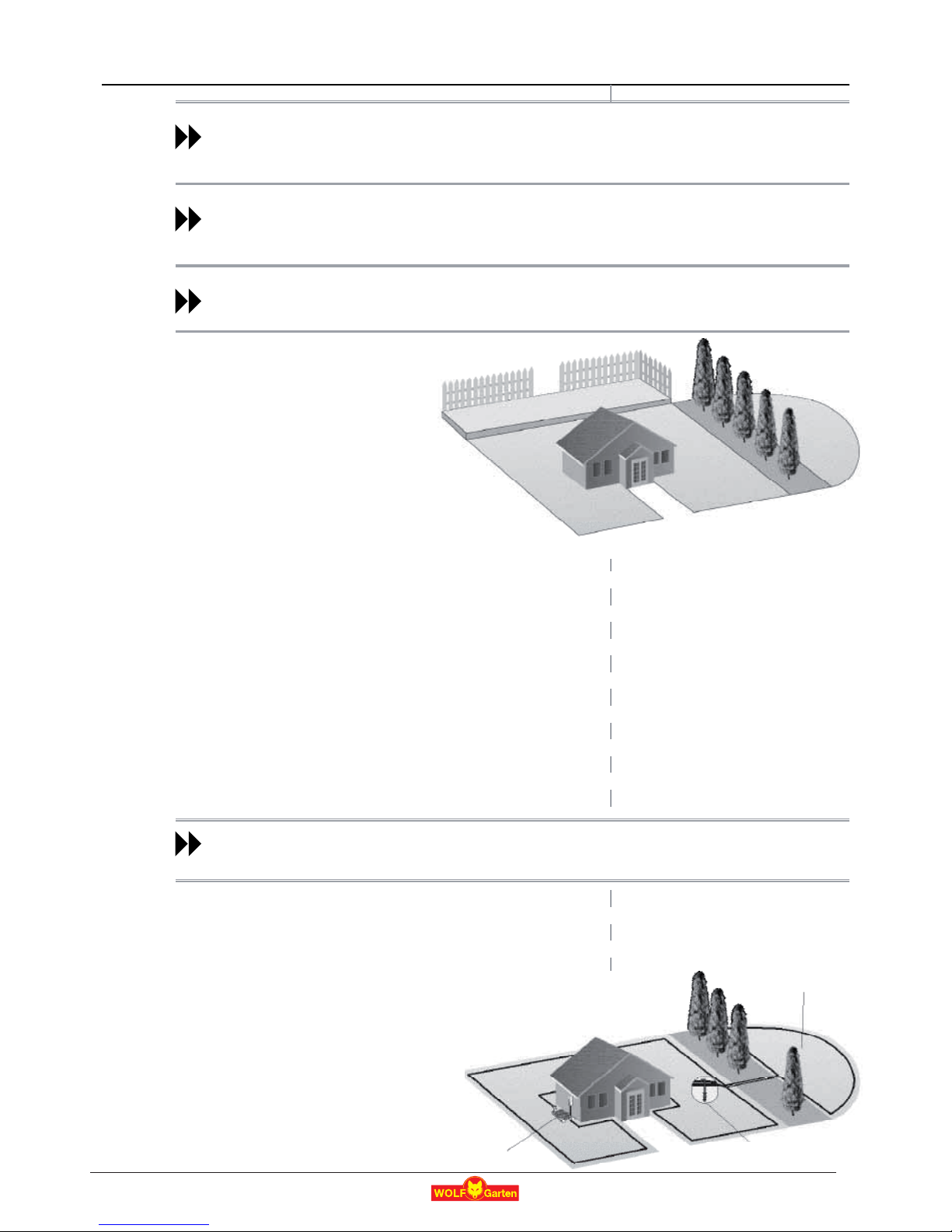
The unit mows. You don’t!
The unit leaves its Base Station on the scheduled mowing time. The unit mows the lawn and then drives itself back to the
Base Station to be charged and ready for its next scheduled mowing.
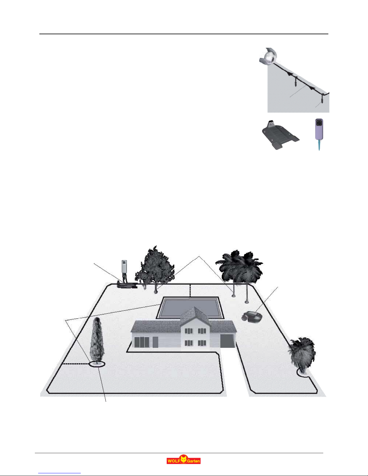
As soon as the unit leaves for mowing, the Base Station automatically triggers a special signal. This signal creates a virtual
wall, visible only to the unit. This signal keeps the unit within the lawn boundaries, and prevents it from entering areas it was
programmed to skip or protect.
The unit detects the signal
and changes direction as it
reaches the wire
Perimeter Wire as a
virtual wall, visible only
to the unit
Tree surrounded by a groove, ditch or flower beds requires a wire around it .
Base Station and Power Box:
- Generates signal along the wire.
- Charges the unit’s battery.
Large trees: the unit is allowed to bump into
them. At this size, the objects do not require
a Perimeter Wire around them.
Peg
Perimeter Wire
Base Station Power Box
7
en
3
Planning Ahead
“Separated Zones” type lawn consists of two
or more zones that are not connected. The
unit cannot drive between these zones.
If you answer “yes” to at least one of the
following questions, your lawn is of the
“Separated Zones” type.
U Are parts of your lawn separated by
fences, sidewalks, or other objects
that the unit cannot pass?
Or:
U Are parts of your lawn separated by a gravel path or similar material
that may damage the mower’s blades?
Or:
U Are zones of your lawns joined by a pass too narrow for the unit to
drive through: less than 1.2 m (4 ft.) in width?
Or:
U Are zones of your lawn situated at lower or higher level?
P If any of the above descriptions fits your lawn, the unit will be set to work
in Separate Zones
If the pass is less than 1.2 m (4 ft.) wide, set the lawn zones as Separated Zones.
See next Section 1.3.
If the pass is more than 5 m (16 ft.) wide, set the lawn as “Main Zone Only” type.
See previous Section 1.2.1 “Main Zone Only”.
Continue reading next Section (Separated Zones), as your lawn may be a combination of more than one type.
1.3 “Separated Zones” Type Lawn
If your lawn does not fit any of these descriptions, it is probably either a “Main Zone Only” or “Main Zone +Sub-
Zone” type. Skip to Section 1.4 – Determine Base Station Location.
P A lawn may consist of up to 2 Separated Zones.
P The mower must be carried or driven to this area manually.
P Any of the 3 types can be in a combination of more than one type of lawn.
1.3.1 Types of Separated Zone setups
A separated zone that can be completely
mowed in a single operation
P If possible, the separated area may be
connected to the main area’s Perimeter Wire.
P Or, it may have to have its own separate
Perimeter Wire.
In that case, it will have to be connected to a
Perimeter Switch (optional accessory).
Separated Zone(s)
Main Zone
Main Zone
Separated Zone
Separated Zone
Base Station
Separated Zone smaller than
200 m² (2150 ft²)
2 wires under
same peg
11
en
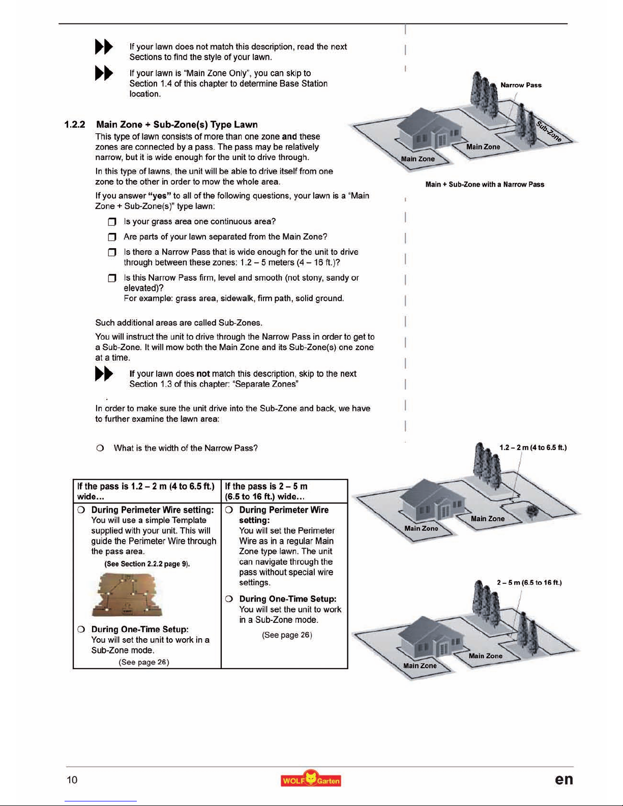
4
Or:
A separated zone that requires more than a
single operation to completely mow the are
a
P
This large separated area needs a separate
operation of the mower.
P
An additional Base Station (optional accessory)
should be
installed in the
add
itional area.
1.4Select Base Station Location
The unit’s Base Station is placed along the Perimeter Wire. This is where the
wire “loop” starts and ends. The Base Station and Power Box have two main
functions
:
P
They generate a small signal along the Perimeter Wire (very low
voltage), which serves as an “invisible wall” setting the lawn boundaries
for the unit.
P
They charge the unit’s batteries.
After completing the One-Time Setup of the Perimeter Wire and the
Base Station, a weekly schedule is set. That’s when the unit starts
m
owing for you for the entire season.
The unit leaves the Base Station on the day and time scheduled according
to a predetermined program for your specific lawn and preferences. It mows
the lawn and it returns to the Base Station for rechar
ging
.
1.4.1Consider the following in order to choose the best location
:
P
Do no
t
place the Base Station within 3 meters (10 ft.) after a corner.
P
The Base Station should be close enough (20
m /
65 ft.) to a wall plug socket (230V / 120V).
P
If the lawn has more than one zone, set
the Base Station within the largest zone.
P
M
ake the Base Station invisible to the street.
P
Prefer a shady spot. This will extend batter
y
life
tim
e
P
Place the Base Station on a relatively level
g
round.
Do not place it on a slope.
P
Place the Base Station away from sprinkler
heads
.
Main Zone
Zone
A
Base Station
l
ocati
on
Bas
e Z
one
Separated Zone larger than 200 m² (2150 ft²)
n P
owe
r B
ox
&
Base Station
Opti
onal Power Box
&
Base Station
Min. 3 m (10 ft
Mi
Min. 3 m
m (10 ft
ft.)
er corn
afte
er corn
12
en
5
Planning Ahead
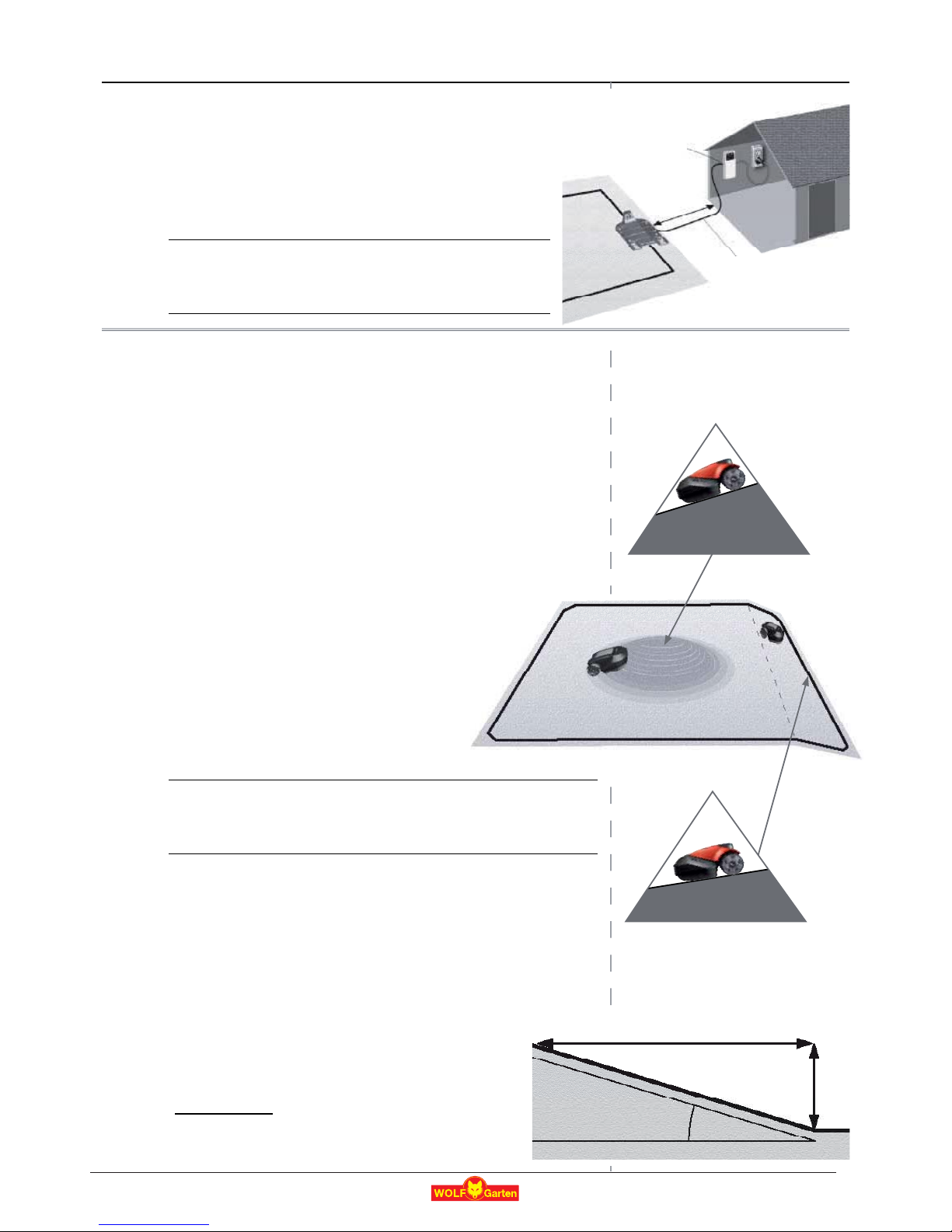
1.5 Determine Power Box Location
P The Power Box will be connected to the Base Station.
P Select a suitable location for the Power Box to be mounted on
the wall near the plug socket.
P The unit’s 20 m (65 ft.) Extension Cable will be connected to
the Power Box. The length of the Extension Cable must not be
changed.
The Power Box is suitable for Outdoor use. Yet, it should be placed
in a sheltered, dry, well ventilated spot.
The Power Box should not be exposed to direct sunlight or rain.
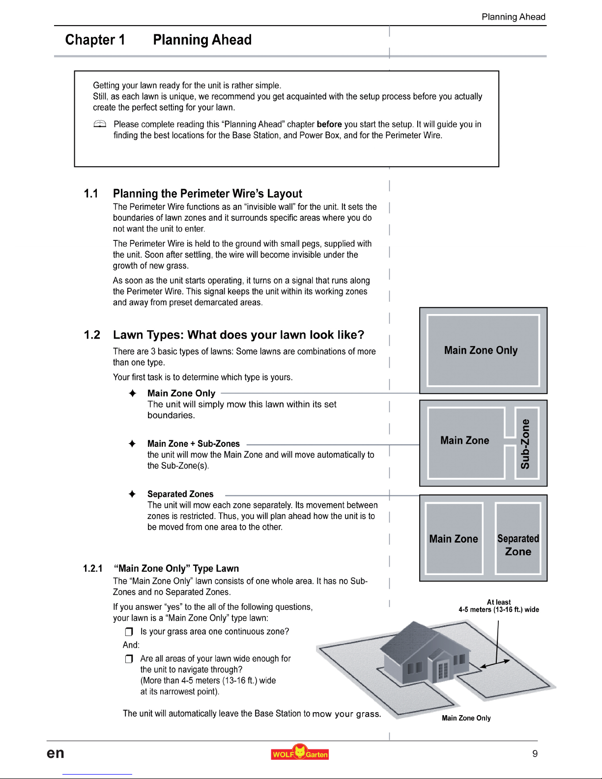
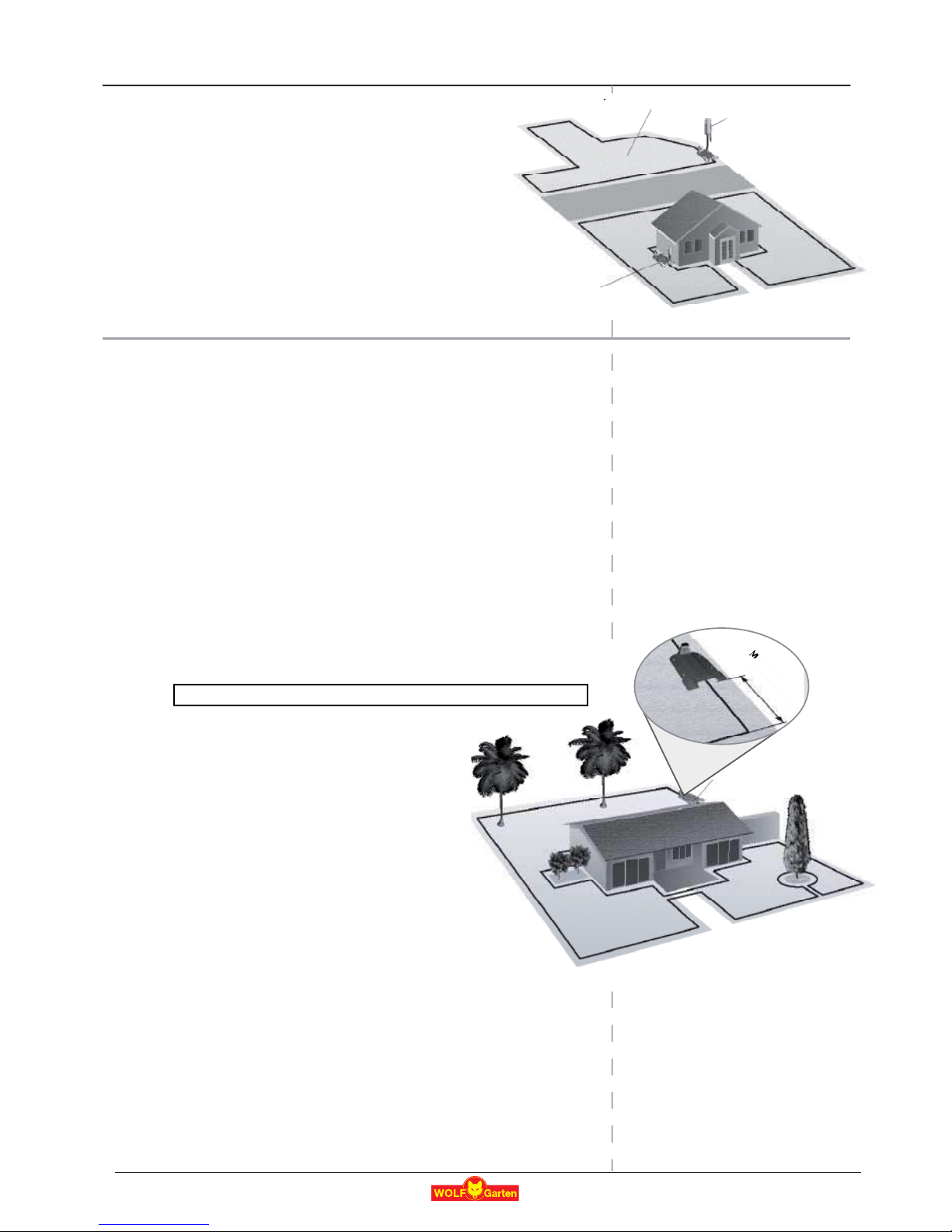
1.6 Planning the Perimeter Wire’s Layout
1.6.1 Objects inside Lawn
P Objects such as flower beds, ponds, or small trees can be protected by
setting “perimeter islands”.
Perimeter Islands are demarcated areas of the lawn, where the unit
does not enter.
P Obstacles that are vertical, relatively rigid, and higher than 15 cm (6
inches), such as trees, phone or power poles, do not need boundaries.
The unit will turn when it collides with these obstacles.
However, for the gentlest and most silent operation, you may prefer to
create Perimeter Islands around all fixed objects in the working area.
P If areas where obstacles are grouped closely together, they should be
demarcated by a single, continuous, Perimeter
Island.
1.6.2 Slopes
Perimeter Slope
P The Perimeter Wire can be laid across a slope
that slants less than 10% (0.35 ft rise per
3.3 ft).
CAUTION! If the Perimeter Wire is laid across a slope steeper than 15%, it
may cause the mower to slip, especially when the grass is wet, and to cross
the wire outside.
) However, if there is a barrier (e.g. fence or wall) that can protect
the mower from slipping off, the Perimeter Wire can be set on that
slope.
In Lawn Slope
P The unit can mow areas inside the working area that slope up to 35%
(1.1 rise per 3.3 ft).
P Tip: If the mower tilts off the ground while climbing a
slope, it is too steep. Exclude this steep area from the
unit’s cutting area.
How to calculate the slope of your lawn?
35 cm (Elevation)
Power Box fixed
to the wall
Max 20 m
(65 ft.)
20 m (65 ft.) Extension
Cable (low voltage)
In Lawn Slope
In Lawn Slope 35%
Perimeter Slope
Perimeter Slope 10%
35 cm (1.1 ft.)
Max 35% slope
100 cm (3.3 ft.)
Elevation
Length
100 cm (Length)
= 35% (Slope)
13
en
Chapter 2 - Initial Setup
6
Planning Ahead
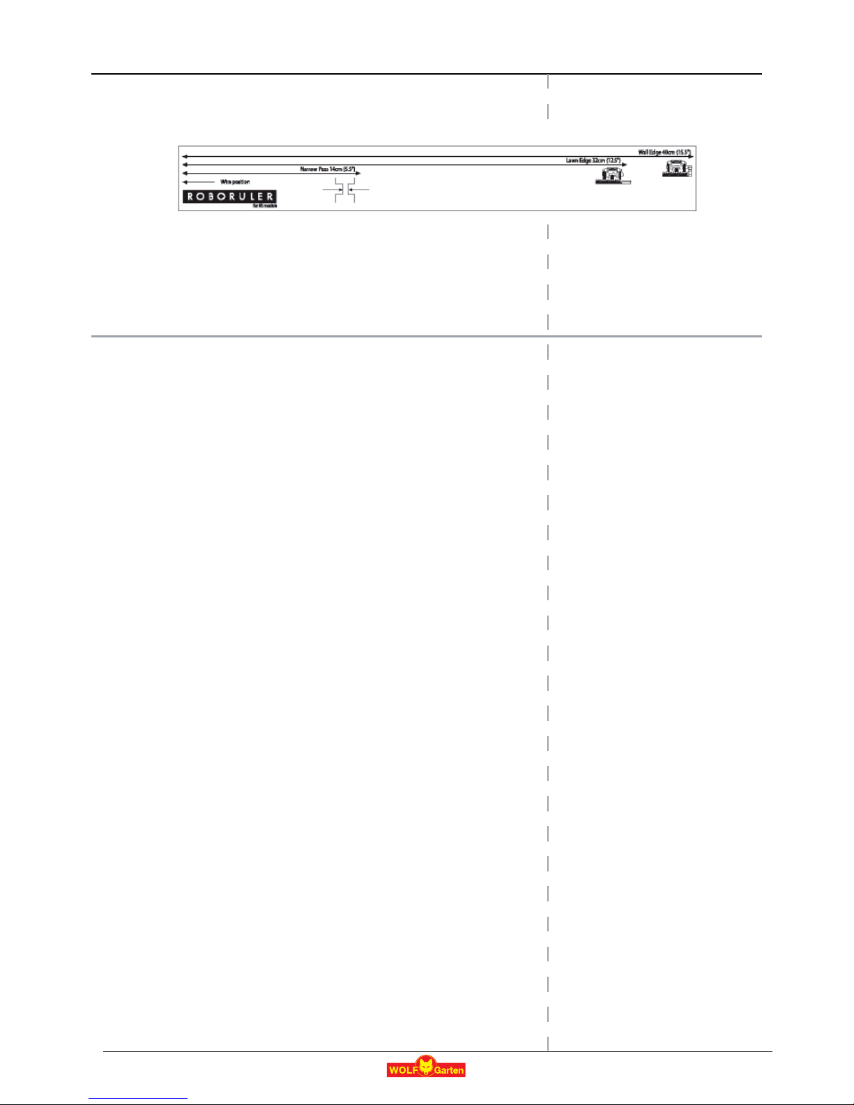
1.6.3 Distances from Edge (Pools, Ponds, Cliffs, etc.)
P RoboRuler is used to measure the distance from the edge, where the
wire is to be placed.
P In certain cases, near bodies of water such as pools and ponds, or
great height differences such as cliffs, it is required to maintain a
greater distance from the Edge (see Section 2.3).
14
en
7
Initial Setup
Chapter 2 Initial Setup
Recommendation, before you start:
During setup, you will insert pegs into the ground. To make this task
smoother, we recommend you mow your lawn and water it before starting.
Getting Ready
Make sure all parts needed for setup are within reach. Have the unit box
nearby, so to have all items available.
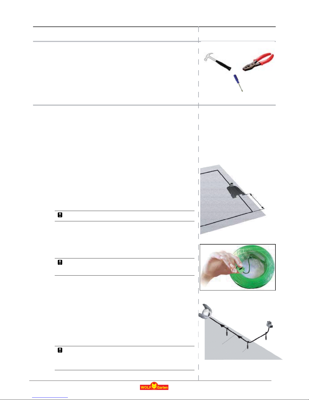
In addition, you will use the following tools: A hammer, a small flat and a
Phillips screwdrivers, Combination Pliers.
2.1 Perimeter Wire Setup
Before you start the setup, you should have a plan for the Perimeter Wire
layout and for the location of the Base Station. Your plan should consider the
following (see Sections 1.4-1.6):
U What type of lawn areas do you prepare?
(Main Zone Only / Main + Sub-Zones / Separated Zones /
combination of types).
U Are there protected or excluded areas on the lawn?
(Perimeter Islands).
U Are there any slopes that the unit should avoid?
U Are there edges of pools, ponds, cliffs etc, that need an extra
distance from the Perimeter Wire?
2.1.1 Starting Point: Perimeter Wire at the Base Station area.
P Place the Base Station, according to your plan, with its front facing Anti
Clockwise on the perimeter.
Do not place the Base Station within 3 m (10 ft.) of a corner
P Select the roll of wire with a green plot connector attached to the end.
The other rolls do not have a connector on the end.
P Pull the plot connector and some the wire, connected to it, out of the
plastic covering.
Do not remove the wire spool from its covering.
The plastic covering is the dispenser for the wire.
P Peg the beginning of the wire to the ground, where Base Station will be
located.
Pegs are supplied in the unit’s box
.
P Pull out 30 cm (12 inches) of wire and leave it loose near the Base
Station location. Later, at the end of the setup this part of the wire will
close the Perimeter Wire loop.
P Start laying the wire in a Anti Clockwise direction.
P Continue to pull the Perimeter Wire out of its covering, laying it loosely
as you walk along the lawn edge.
If you get to any area /object that needs care or special boundaries,
make sure you carefully lay the Perimeter Wire as needed.
The next Sections deal with such special cases.
Hammer
Combination Pliers
Small flat and Philips
screwdrivers
Anti Clockwise
direction of wire layout
Perimeter Wire – do not
remove the plastic covering
Leave 30 cm
(12 inches)
starting point
Min. 3 m (10 ft.)
from any corner
15
en
8
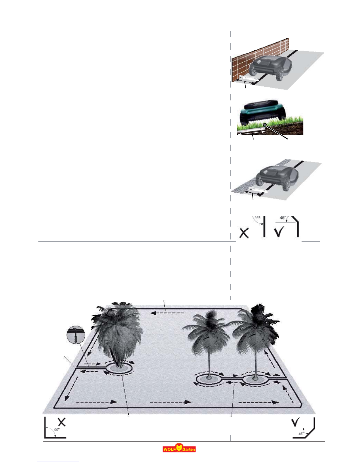
2.1.2 Laying the Perimeter Wire
P The Perimeter Wire is secured to the ground by the
pegs supplied with the unit. Insert pegs every few
meters and at corners.
At this early stage set a minimum number of pegs. Later,
after testing the wire setup, you will insert all necessary pegs.
P After uncoiling Sections of wire, before inserting pegs, use the
RoboRuler to determine the distance of the wire from lawn
edge or obstacles.
RoboRuler is supplied with the unit
U If the edge is slopping (max 15% is allowed) or a wall –
the distance from the edge is 40 cm (1.3 ft.).
U If the edge is a flat area or a cliff –
the distance from the edge is 32 cm (1 ft.).
P If there is a hard obstacle (that does not need protection as a
Perimeter Island) near the perimeter– Perimeter Wire should be at least
1 m (3.3 ft.) away from it.
P If the edge is not a wall, a fence or other obstacle -
you may move the Perimeter Wire closer to the edge.
Test this short distance before fastening the pegs into the ground.
P Maintain a 45º angle in all left-turn corners when laying the wire along
the perimeter. It is not necessary to maintain 45º angle on right-turn
corners along the perimeter. It is not necessary to maintain 45º angle
along corners of an island inside the lawn (example: around a swimming
pool).
P Continue laying the wire, according to your plan.
Gradually pull the wire out of its dispenser and lay it loosely as you are
moving in a Anti Clockwise direction.
2.2 Special cases of Perimeter Wire setup
2.2.1 Perimeter Islands
P Continue uncoiling the wire, moving from the edge towards the
protected object.
P Peg the Perimeter Wire around the protected object in a Clockwise
direction.
32 cm (1 ft.)
Area outside perimeter – same basic level and
free of protected objects.
Area outside perimeter – has a wall as an
protected objects.
Min. distance between islands: 1.5 m (4.9 ft.).
Otherwise, demarcate jointly as one island.
Perimeter Wire position
2 wires under
same peg
Perimeter
Wire
Direction of setup: Clockwise around obstacle
40 cm (1.3 ft.)
40 cm (1.3 ft.)
Wire
Slopping -
max 15%.
16
en
 Loading...