

Page 1

INSTALLATION GUIDE
E Series Built-In Ovens
Page 2

Contents
Important Note
Wolf E Series Built-In Ovens . . . . . . . . . . . . . . . . . . . . 3
E Series Oven Specifications . . . . . . . . . . . . . . . . . . . . 4
E Series Oven Installation . . . . . . . . . . . . . . . . . . . . . . 15
Service Information . . . . . . . . . . . . . . . . . . . . . . . . . . . 18
Features and specifications are subject to change at any time
without notice. Visit wolfappliance.com/specs for the most
up-to-date information.
IMPORTANT NOTE: Throughout this guide, dimensions in
parentheses are millimeters unless otherwise specified.
o ensure the safe and efficient use of Wolf equipment,
T
please take note of the following types of highlighted
information throughout this guide:
IMPORTANT NOTE highlights information that is especially
important.
CAUTION signals a situation where minor injury or product
damage may occur if instructions are not followed.
WARNING states a hazard that may cause serious injury or
death if precautions are not followed.
Page 3
Wolf E Series Built-In Ovens 3
wolfappliance.com/specs
E Series Oven Installation
IMPORTANT NOTE: T
his installation must be completed
by a qualified installer or Wolf authorized service center
technician.
Read this entire installation guide prior to installation and
save for the local inspector’s reference. The homeowner
should keep this installation guide for future reference.
This appliance must be installed in accordance with
National Electrical Codes, as well as all state, municipal
and local codes. The correct voltage, frequency and
amperage must be supplied to the appliance from a dedicated, grounded circuit which is protected by a properly
sized circuit breaker or time delay fuse. The proper
voltage, frequency, and amperage ratings are listed on the
product rating plate.
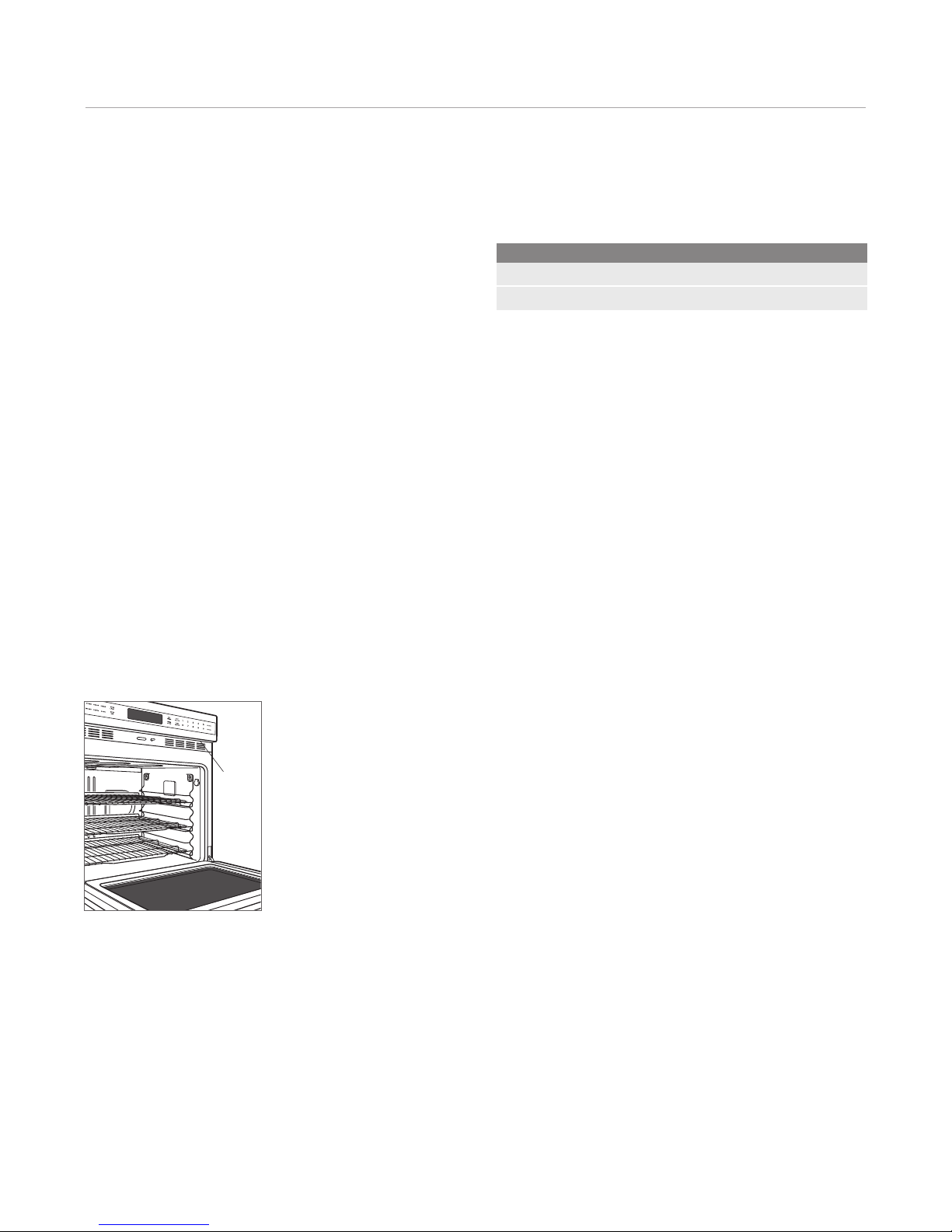
Record the model and serial numbers before installing
the E series oven. Both numbers are listed on the product
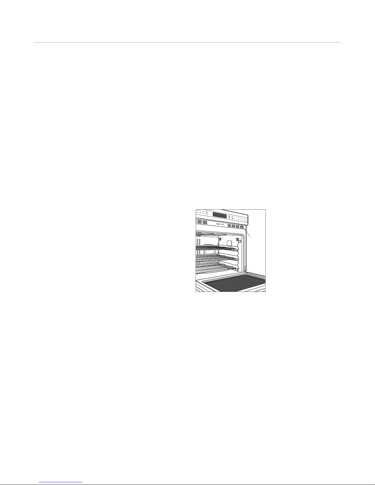
rating plate located below the control panel. The oven
door must be open to view the rating plate. Refer to the
illustration below.
olf E Series Oven
W
Model Number
Serial Number
RATING
PLATE
Location of rating plate.
Page 4
E Series Oven Specifications 4
233/4" (603)
BEHIND FRAME
2
7
7
/8"
(708)
281/4"
(718)
2
9
7
/8"
(
759)
233/4"
(
603)
CONDUIT
CHANNEL
OPEN OVEN DOOR
TOP VIEW
2
2"
(559)
11/4"
(
32)
1" (25)
17/8"
(48)
17/8"
(48)
RIGHT SIDE VIEW
2
7
1
/16"
(687)
297/8"
(759)
25/8"
(67)
233/4" (603)
BEHIND FRAME
503/8"
(1280)
491/2"
(1257)
281/4"
(718)
297/8"
(759)
233/4"
(603)
OPEN OVEN DOOR
TOP VIEW
25/8"
(67)
22"
(559)
11/4"
(32)
1" (25)
17/8"
(48)
17/8"
(48)
RIGHT SIDE VIEW
297/8"
(759)
CONDUIT
CHANNEL
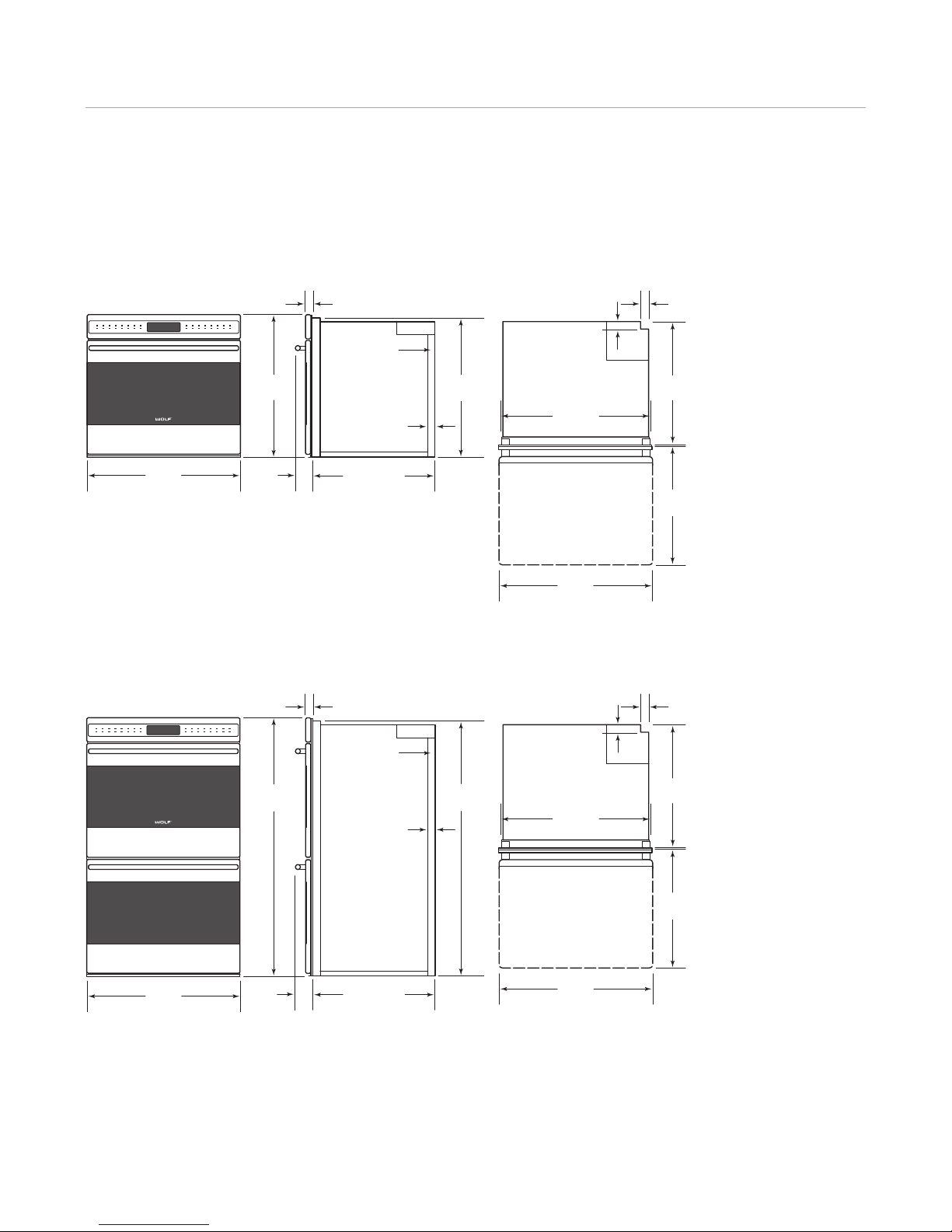
Overall Dimensions
E SERIES SINGLE OVEN
odel SO30-2U/S shown
M
E SERIES DOUBLE OVEN
Model DO30-2U/S shown
Page 5

E Series Oven Specifications 5
wolfappliance.com/specs
E Series Built-In Ovens
or ease of installation, Wolf recommends using a 33"
F
(838) wide cabinet with the E series oven. The installation
opening must have a flat, level base platform to support
the oven. The single oven requires a minimum base
support of 250 lbs (113 kg). The double oven requires a
minimum base support of 400 lbs (181 kg).
COMBINATION INSTALLATIONS
Wolf built-in ovens are designed and agency approved for
installation with Wolf cooktops, microwaves and warming
drawers only. The nominal width of the built-in oven
should match the nominal width of the cooktop. A built-in
oven cannot be installed below a Wolf rangetop.
STANDARD INSTALLATION
A minimum 24" (610) of usable cabinet depth is required
for standard installations, or the back panel of the cabinet
may need to be removed for proper installation. The electrical box must be flush with the back panel of the cabinet.
For standard installations, the E series oven is installed by
inserting into cabinetry from the front. The oven has a face
trim on all four sides and will overlap stiles and rails. The
trim overlaps
3
and
/4" (19) on each side.
FLUSH INSET INSTALLATION
5
/8" (16) on the top,1/8" (3) on the bottom
A minimum 25" (635) of usable cabinet depth is required
for flush inset installations, or the back panel of the
cabinet may need to be removed for proper installation.
The electrical box must be flush with the back panel of the
cabinet.
For flush inset installations, the inside edges of the rough
opening must be finished, as they will be exposed when
the oven door is open. These edges should be stained
instead of having a laminated surface, to avoid damage
from high temperatures during self-clean.
For typical combination installations, refer to the illustrations on pages 11–14.
The single oven may be installed next to another E series
single oven. You must allow for a 2
1
/2" (64) space between
the oven rough openings. Also, a separate inner wall is
required for each oven between openings.
Page 6

E Series Oven Specifications 6
Electrical Requirements
IMPORTANT NOTE: U
nless you are using cabinets deeper
than 24" (610) for a standard installation or 25" (635) for a
flush inset installation, it is recommended that the electrical supply for the oven be placed in an adjacent cabinet
within reach of the conduit. Choose the electrical location
shown in the illustrations on the following pages that best
suits your installation.
E SERIES SINGLE OVEN
• Power supply: 240 / 208 V AC, 60 Hz with 30 amp
service.
• Maximum connected load: 5.1 kW.
• Total amps: 21 amps.
• Supply wire minimum size: L1, L2 and ground—
10 AWG.
E SERIES DOUBLE OVEN
• Power supply: 240 / 208 V AC, 60 Hz with 50 amp
service.
• Maximum connected load: 8.9 kW.
• Total amps: 37 amps.
• Supply wire minimum size: L1, L2 and ground—
10 AWG.
he E series oven is provided with a conduit consisting of
T
two insulated hot lead conductors and an insulated
ground conductor. The wiring diagram covering the control
circuit is located on the top of the E series oven in a
sealed plastic bag.
UL installations: Attach the conductors to the residence
wiring in accordance with National Electrical Codes and all
state, municipal and local codes.
CSA installations: Attach the conductors to the electrical
box provided. Then connect the residence wiring to the
electrical box in accordance with all national, provincial
and local codes.
The complete appliance must be properly grounded at
all times when electrical power is applied.
Grounding through the neutral conductor is prohibited
for new branch-circuit installations (1996 NEC); mobile
homes and recreational vehicles, or where local codes
prohibit grounding through the neutral conductor.
If aluminum house supply wiring is utilized, splice the
appliance copper wire to the aluminum house wiring
using special connectors design and agency certified
for joining copper and aluminum. Follow the connector
manufacturer's recommended procedure carefully.
Improper connection can result in a fire hazard.
IMPORTANT NOTE: You must follow all National Electrical
Code regulations. In addition, be aware of local codes and
ordinances when installing your service.
IMPORTANT NOTE: Performance may be compromised if
the electrical supply is less than 240 volts.
Page 7
E Series Oven Specifications 7
D
IMENSION WILL VARY*
43/4" (
121)
TYPICAL*
36" (914)
F
LOOR TO
COUNTERTOP
*Dimension must accommodate height of oven trim.
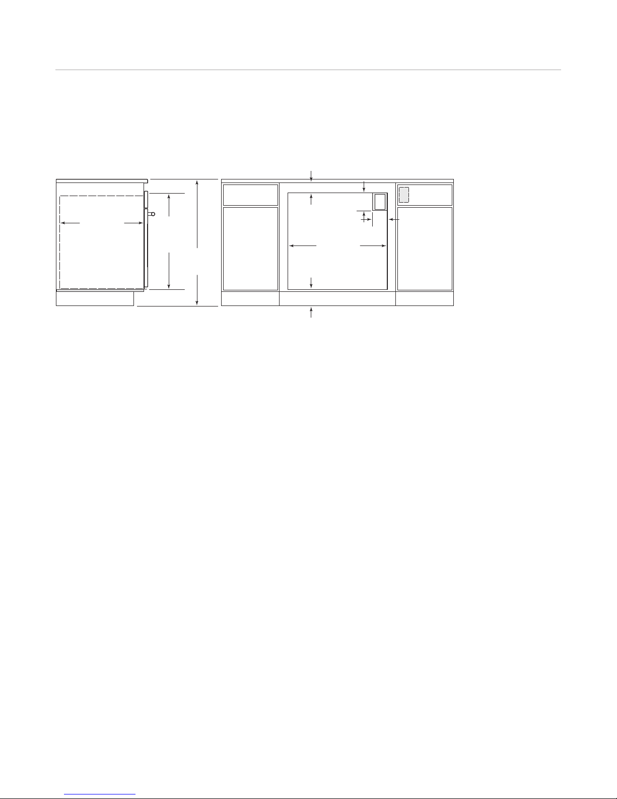
NOTE: Location of electrical supply within opening may require additional cabinet depth. Dashed line represents profile of unit.
E
2
8
1
/2" (
724)
O
PENING WIDTH
273/16"
(
691)
O
PENING
HEIGHT
24" (
610) min
OPENING DEPTH
E
5
"
(127)
4
"
(102)
F
RONT VIEWSIDE VIEW
wolfappliance.com/specs
E Series Single Oven
STANDARD INSTALLATION
Page 8
E Series Oven Specifications 8
67" (1702)
TYPICAL*
495/8"
(1260)
O
PENING
H
EIGHT
E
E
E
281/2" (724)
OPENING WIDTH
E
5"
(127)
4"
(102)
24" (610) min
OPENING DEPTH
*Dimension must accommodate height of oven trim.
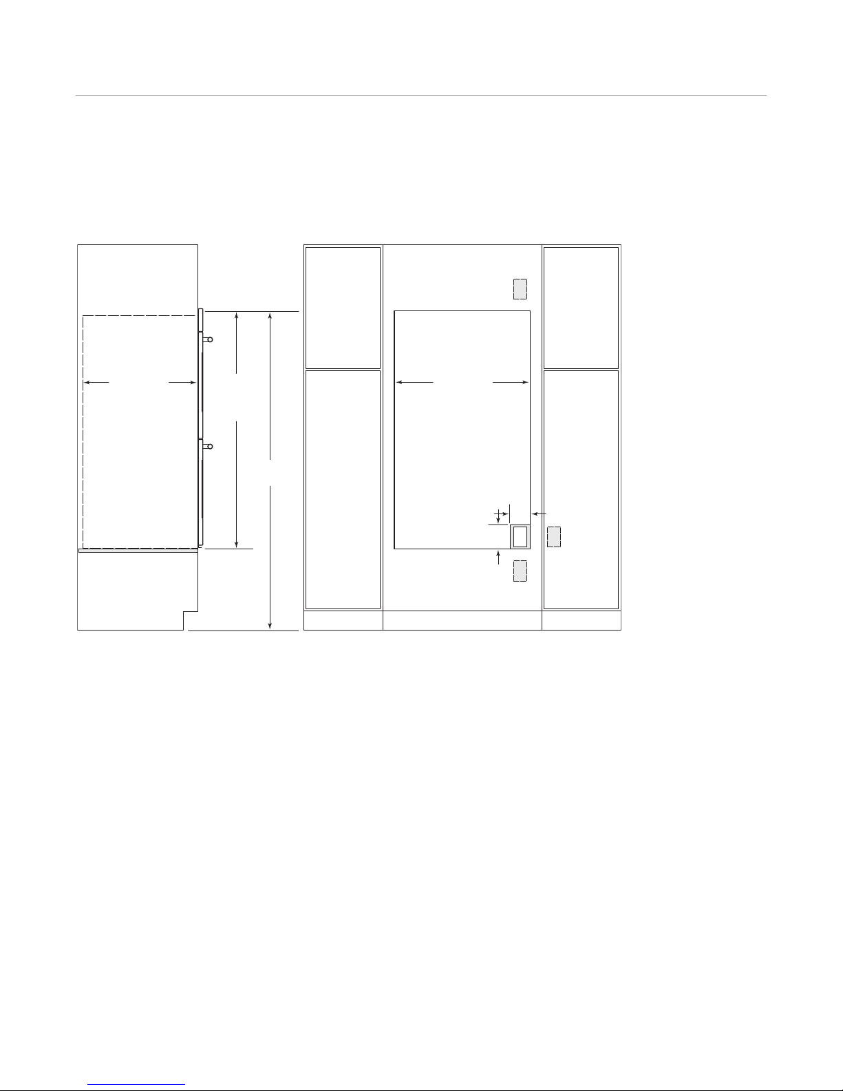
NOTE: Location of electrical supply within opening may require additional cabinet depth. Dashed line represents profile of unit.
FRONT VIEWSIDE VIEW
E Series Double Oven
STANDARD INSTALLATION
Page 9
E Series Oven Specifications 9
273/16"
(691)
O
PENING
HEIGHT
281/2"
(
724) min
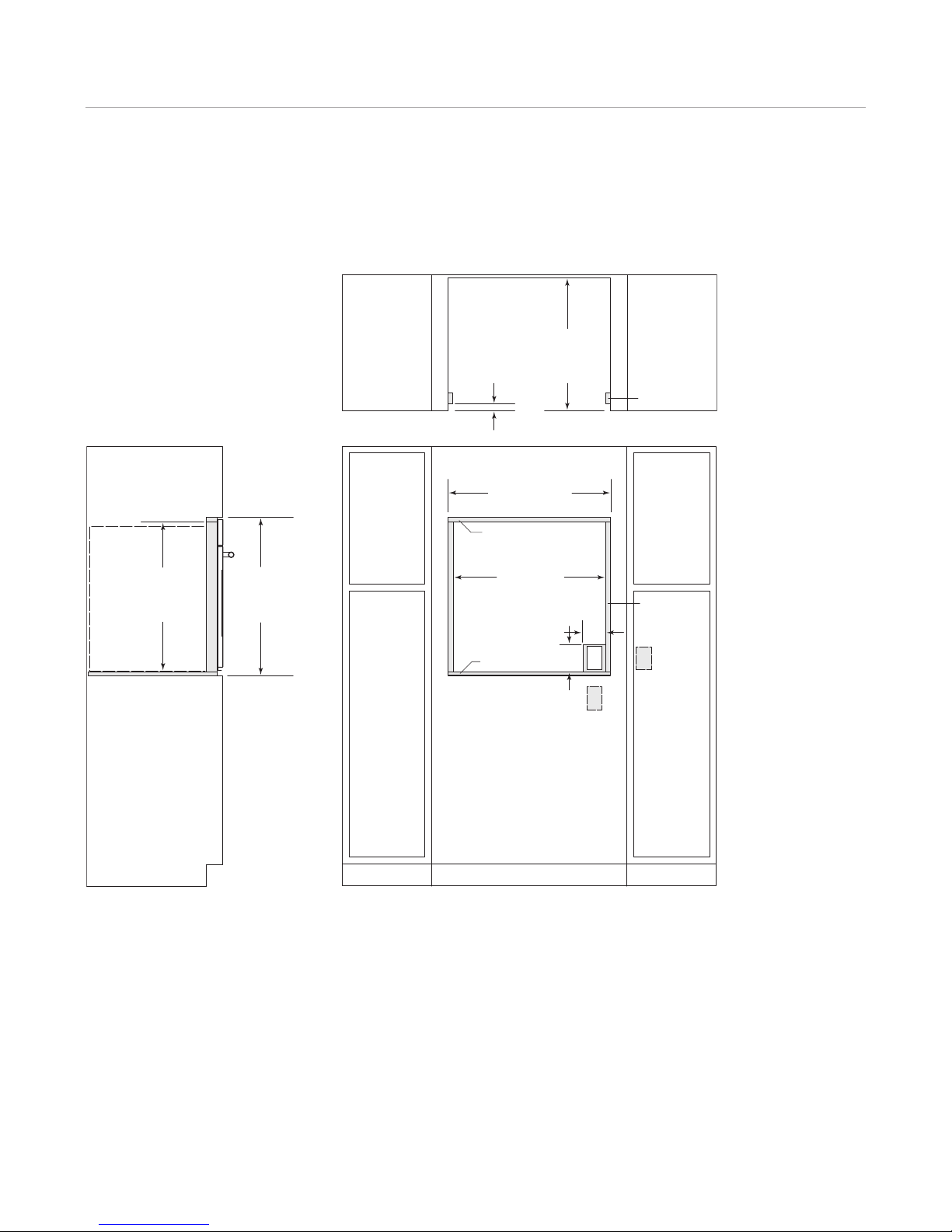
FLUSH INSET
HEIGHT
281/2" (724)
O
PENING WIDTH
303/8" (772) min
FLUSH INSET WIDTH
7
/8"(
22)
TOP CLEAT
7
/16" (11)
PLATFORM*
S
IDE CLEATS
243/4"
(629) min
FLUSH INSET
DEPTH
1" (
25)
*Platform must support 250 lbs (113 kg).
NOTE: Location of electrical supply within opening may require additional cabinet depth. Dashed line represents profile of unit.
FRONT VIEWSIDE VIEW
TOP VIEW
1" (25)
SIDE CLEATS
5"
(127)
4"
(102)
E
E
E
wolfappliance.com/specs
E Series Single Oven
FLUSH INSET INSTALLATION
Page 10
E Series Oven Specifications 10
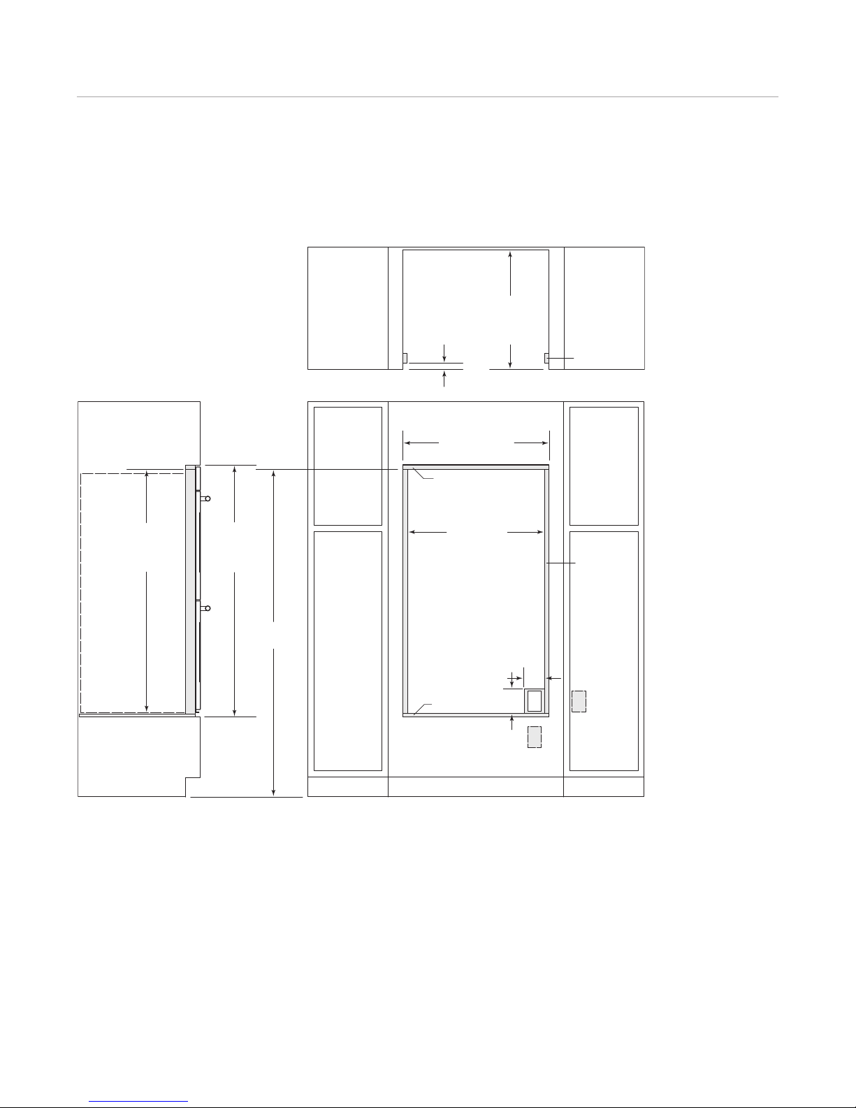
495/8"
(1260)
OPENING
HEIGHT
5015/16"
(1294) min
FLUSH INSET
HEIGHT
281/2" (724)
OPENING WIDTH
303/8" (772) min
FLUSH INSET WIDTH
7
/8"(22) T
OP CLEAT
7
/16" (11)
PLATFORM*
S
IDE CLEATS
243/4"
(629) min
FLUSH INSET
DEPTH
1" (
25)
*Platform must suppor t 400 lbs (181 kg).
NOTE: Location of electrical supply within opening may require additional cabinet depth. Dashed line represents profile of unit.
FRONT VIEWSIDE VIEW
TOP VIEW
1" (25)
SIDE CLEATS
5"
(127)
4"
(102)
E
E
E
67" (1702)
TYPICAL
E Series Double Oven
FLUSH INSET INSTALLATION
Page 11
E Series Oven Specifications 11
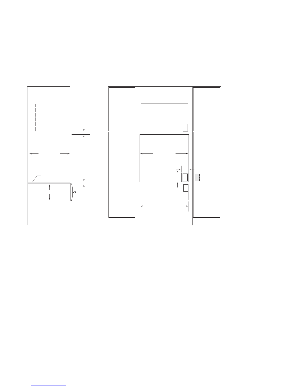
24" (
610) min
O
PENING DEPTH
*Platform must suppor t 250 lbs (113 kg).
NOTE: Location of electrical supply within oven opening may require additional cabinet depth.
FRONT VIEWSIDE VIEW
285/8" (727)
WARMING DRAWER
OPENING WIDTH
281/2" (724)
O
VEN OPENING WIDTH
E
E
MICROWAVE
OPENING
273/16"
(
691)
11/2" (38)
min
91/8" (232)
3
/4" (19)
min
PLATFORM*
E
E
5"
(127)
4"
(102)
wolfappliance.com/specs
E Series Single Oven
STANDARD INSTALLATION WITH MICROWAVE AND WARMING DRAWER
Page 12
E Series Oven Specifications 12
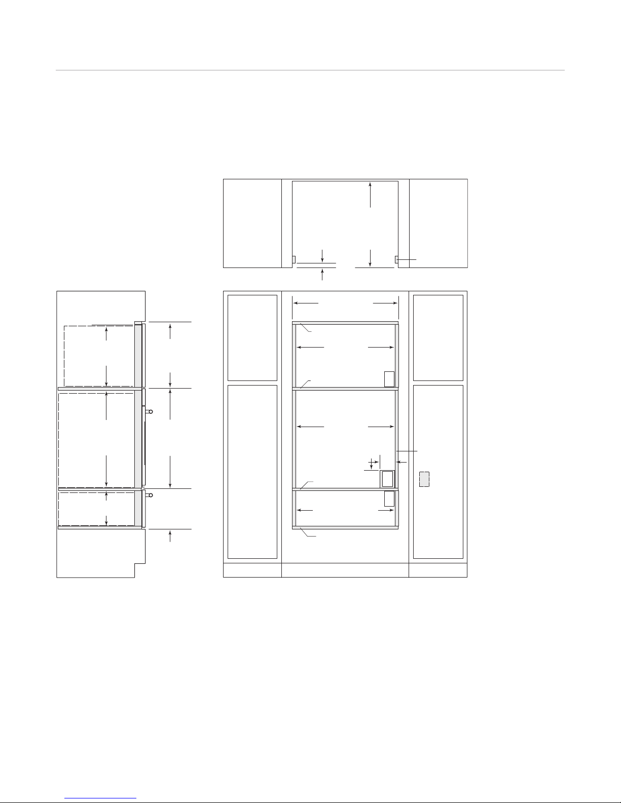
303/8" (772) min
FLUSH INSET WIDTH
S
IDE CLEATS
243/4"
(
629) min
F
LUSH
I
NSET
D
EPTH
1
"
(25)
*Platform must suppor t 250 lbs (113 kg).
NOTE: Location of electrical supply within oven opening may require additional cabinet depth. Dashed line represents profile of unit.
FRONT VIEWSIDE VIEW
TOP VIEW
105/8"
(270)
FLUSH INSET
HEIGHT
91/8" (232)
OPENING HEIGHT
E
1" (25) PLATFORM
285/8" (727)
WARMING DRAWER
OPENING WIDTH
17" (
432)
OPENING
HEIGHT
181/2" (
470)
F
LUSH INSET
H
EIGHT
271/2" (699)
STANDARD MICROWAVE
OPENING WIDTH
E
281/2" (724)
E SERIES OVEN
OPENING WIDTH
11
/16" (17) T
OP CLEAT
9
/16" (14)
PLATFORM*
1" (25)
SIDE CLEATS
E
E
5"
(127)
4"
(102)
273/16"
(691)
OPENING
HEIGHT
281/8"
(714) min
FLUSH INSET
HEIGHT
1
1
1
/16" (43) PLATFORM
E Series Single Oven
FLUSH INSET INSTALLATION WITH STANDARD MICROWAVE AND WARMING DRAWER
Page 13
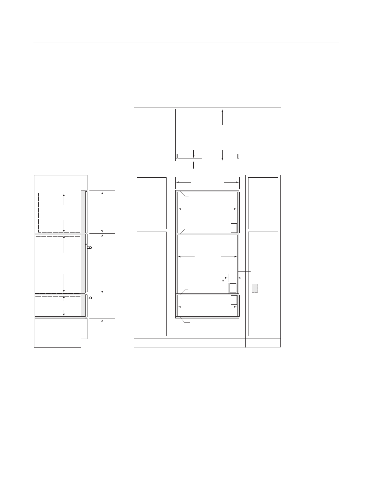
E Series Oven Specifications 13
303/8" (772) min
FLUSH INSET WIDTH
S
IDE CLEATS
243/4"
(
629) min
F
LUSH
I
NSET
D
EPTH
1
"
(25)
*Platform must suppor t 250 lbs (113 kg).
NOTE: Location of electrical supply within oven opening may require additional cabinet depth. Dashed line represents profile of unit.
FRONT VIEWSIDE VIEW
TOP VIEW
105/8"
(270)
FLUSH INSET
HEIGHT
91/8" (232)
OPENING HEIGHT
E
1" (25) PLATFORM
285/8" (727)
WARMING DRAWER
OPENING WIDTH
187/8" (
479)
OPENING
HEIGHT
201/8"
(
511)
F
LUSH INSET
HEIGHT
271/2" (699)
CONVECTION MICROWAVE
OPENING WIDTH
E
281/2" (724)
E SERIES OVEN
OPENING WIDTH
1
/2" (
13)
T
OP CLEAT
9
/16" (14)
PLATFORM*
1" (25)
SIDE CLEATS
E
E
5"
(127)
4"
(102)
273/16"
(691)
OPENING
HEIGHT
281/8"
(714) min
FLUSH INSET
HEIGHT
15/8" (41) PLATFORM
wolfappliance.com/specs
E Series Single Oven
FLUSH INSET INSTALLATION WITH CONVECTION MICROWAVE AND WARMING DRAWER
Page 14
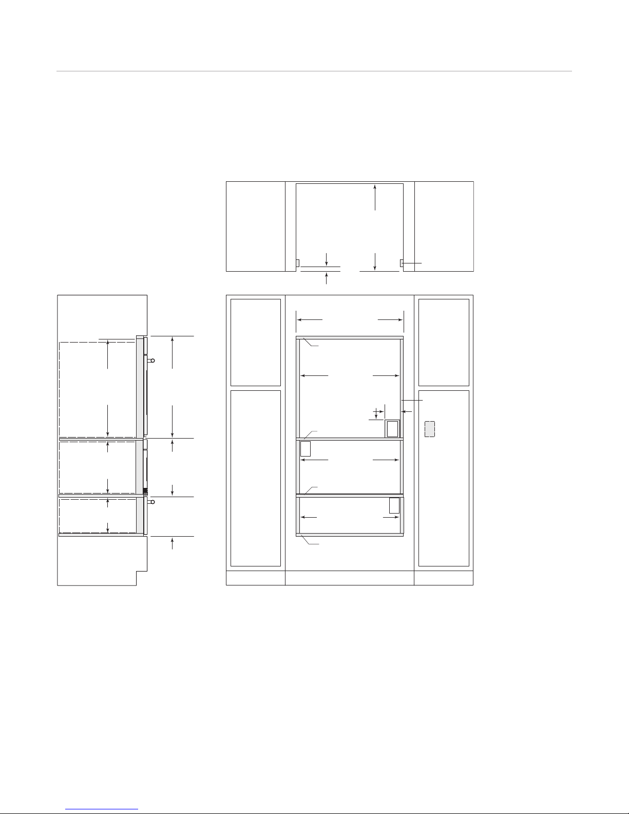
E Series Oven Specifications 14
273/16"
(691)
OPENING
H
EIGHT
281/8"
(714) min
FLUSH INSET
HEIGHT
281/2" (724)
E SERIES OVEN
OPENING WIDTH
303/8" (772) min
FLUSH INSET WIDTH
281/2" (724)
DRAWER MICROWAVE
OPENING WIDTH
E
7
/8"(
22)
TOP CLEAT
9
/16" (14)
PLATFORM*
5
/8" (16) PLATFORM
S
IDE CLEATS
243/4"
(
629) min
F
LUSH
I
NSET
D
EPTH
11/4" (
32)
F
OR MICROWAVE
1" (25) F
OROVEN
A
ND WARMING
DRAWER
*Platform must suppor t 250 lbs (113 kg.
NOTE: Location of electrical supply within oven opening may require additional cabinet depth. Dashed line represents profile of unit.
FRONT VIEWSIDE VIEW
TOP VIEW
143/4" (375)
OPENING
HEIGHT
153/8"
(391)
FLUSH INSET
HEIGHT
1" (25)
SIDE CLEATS
105/8"
(270)
FLUSH INSET
HEIGHT
91/8" (232)
OPENING HEIGHT
E
1" (25) PLATFORM
285/8" (727)
WARMING DRAWER
OPENING WIDTH
E
E
5"
(127)
4"
(102)
E Series Single Oven
FLUSH INSET INSTALLATION WITH DRAWER MICROWAVE AND WARMING DRAWER
Page 15
E Series Oven Installation 15
wolfappliance.com/specs
Install the Oven
IMPORTANT NOTE: B
finished flooring to avoid damage to the floor.
Move the oven into position near the installation opening.
Remove and discard packing materials. Remove the box
containing oven components found in each oven cavity.
The oven is very heavy—use caution when lifting. Do
not lift the oven by the door handle. This will damage
the oven door and hinges.
OVEN DOOR REMOVAL
To reduce the weight of the oven and ease installation,
oven door(s) may be removed.
To remove, open oven door all the way. Flip down the
hinge latch on each side, then close the door. While
holding the door on each side, lift up. Continue to push
the door closed and pull it away from the oven frame.
To reinstall, insert both hanger arms into the oven frame
openings. Open the door. You should hear a ”click” as the
door is set into place. Move the hinge levers back to the
locked position. Check that the door is free to open and
close. If not, repeat the process.
efore moving the oven, protect any
ELECTRICAL CONNECTIONS
Verify that power is disconnected from the electrical
box before proceeding.
With the oven positioned directly in front of the installation
opening, feed the conduit through the opening in the
cabinet platform (if applicable). Depending on local codes,
connect the oven to the electrical supply following these
steps for a three-wire or four-wire system:
1) Connect the appliance black wire to the black (L1)
power supply wire in the electrical box.
2) Connect the appliance red wire to the red (L2) power
supply wire in the electrical box.
3) Connect the appliance bare ground wire to the
green/bare ground house wire in the electrical box.
4) For a four-wire system only, leave the white neutral
wire in the house electrical box floating (not connected
to anything) but sealed off with a wire cap.
Page 16
E Series Oven Installation 16
Install the Oven
POSITION THE OVEN
Carefully lift the oven up to the opening. Resting the oven
on the cabinet base platform, slide the oven into the
opening until it is approximately 6" (152) from full insertion.
Make sure the conduit slides through the opening in the
platform as the oven is moved into place.
IMPORTANT NOTE: The conduit must fit into the recessed
area along the right rear edge of the oven. Make sure it is
not trapped between the oven and cabinet wall.
IMPORTANT NOTE: To avoid interference, a 90° door stop
may be required for any appliance or cabinet door installed
next to an E series oven with tubular handle.
Do not block the exhaust vent located at the bottom of
the oven. It must remain clear for proper ventilation.
MOUNT OVEN TO CABINETRY
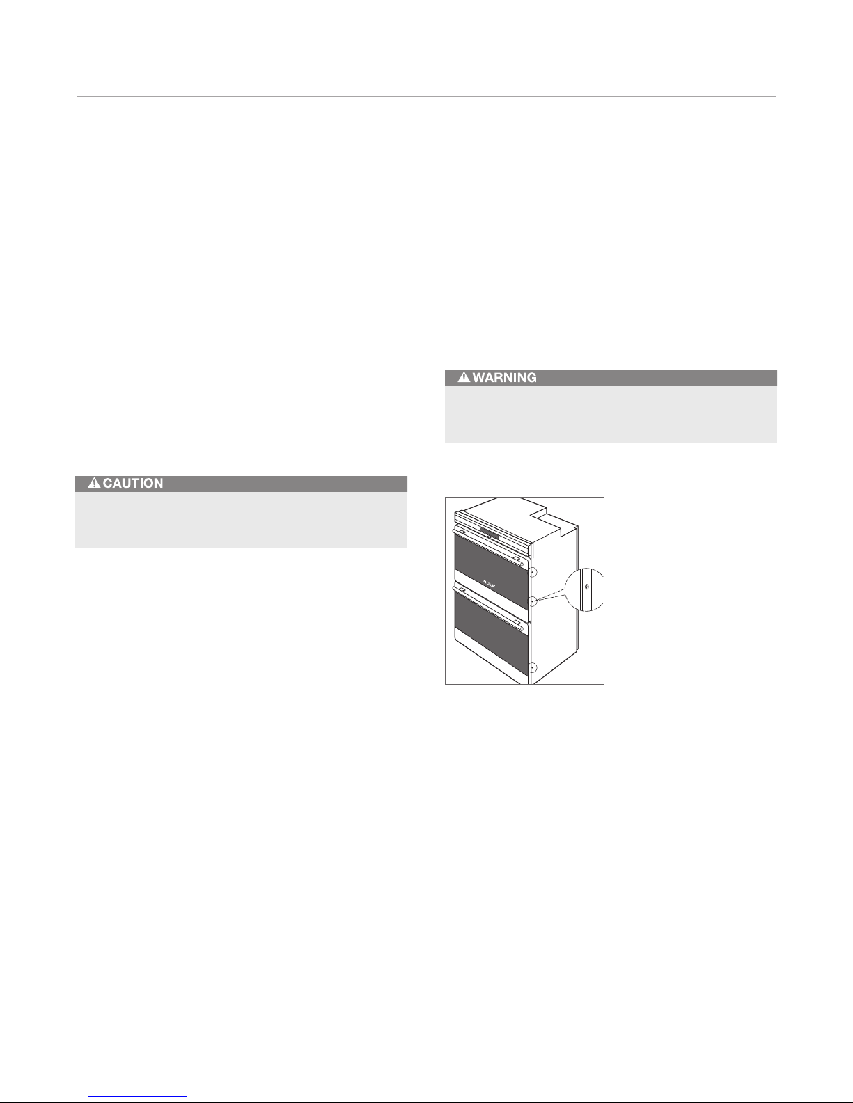
Once the oven is fully inserted into the opening, locate the
mounting holes on the oven side trim. There are four
mounting holes for a single oven and six for a double
oven. Refer to the illustration below. Use a
1
/16" drill bit to
drill pilot holes into the cabinet. Using the wood screws
provided, secure the oven to the cabinet.
Failure to install the mounting screws may cause the
oven to tip forward during use.
Location of mounting holes.
Page 17

E Series Oven Installation 17
wolfappliance.com/specs
Verify Oven Operation
npack the box containing the oven components found in
U
each oven cavity. Install the oven rack guides onto the
shoulder screws located on the interior side walls of the
oven. Slide the oven racks onto the rack guides and place
the broiler pan in the oven.
Before operating the oven, be sure to read the entire
use & care guide included with the oven for important
safety, operating and warranty information.
Turn on the electrical supply to the oven. Set the time of
day by pressing the CLOCK touch pad, input the time by
using the number pads, then touch ENTER.
Select any of the ten cooking modes on the control panel.
Verify that the oven is coming up to temperature. For the
double oven, be sure to verify operation of both ovens.
IMPORTANT NOTE: A
may be noticed during the initial break-in period. Refer to
the E series built-in ovens use & care guide for additional
information.
small amount of smoke and odor
Page 18
Service Information 18
Troubleshooting
IMPORTANT NOTE: I
properly, follow these troubleshooting steps:
• Verify that electrical power is being supplied to the
oven.
• Check the electrical connections to ensure that the
installation has been completed correctly.
• Refer to the troubleshooting guide in the E series
built-in ovens use & care guide.
• If the oven still does not operate properly, contact a
Wolf authorized service center. Do not attempt to repair
the oven yourself. Wolf is not responsible for service
required to correct a faulty installation.
f the E series oven does not operate
Service Information
f service is necessary, maintain the quality built into your
I
E series oven by calling a Wolf authorized service center.
To obtain the name and number of a Wolf authorized
service center, check the contact & support section of our
website, wolfappliance.com or call Wolf customer service
at 800-222-7820.
When calling for service, you will need the model and
serial number of the E series oven. Both numbers are
listed on the product rating plate located below the control
panel. The oven door must be open to view the rating
plate. Refer to the illustration below.
RATING
PLATE
Location of rating plate.
Page 19

The information and images in this guide are the copyright property of Wolf Appliance, Inc. Neither this guide nor any information or images contained herein
may be copied or used in whole or in part without the express written permission of Wolf Appliance, Inc. ©Wolf Appliance, Inc. all rights reserved.
Wolf, Wolf & Design, Wolf Gourmet, W & Design and the color red as applied to knobs are registered trademarks and service marks of Wolf Appliance, Inc.
Sub-Zero, Sub-Zero & Design, Dual Refrigeration, Constant Care and The Living Kitchen are registered trademarks and service marks of Sub-Zero, Inc.
(collectively,the“Company Marks.”) All other trademarks or registered trademarks are property of their respective owners in the United States and other countries.
Page 20

WO LF AP PLIAN CE, IN C. P. O . BOX 4 4848 MA DISON , W I 5374 4 WOL FAPPLI ANCE. COM 80 0.222 .7820
816 989 RE V-A 11 /2010
 Loading...