

Page 1
Service Manual
Lichtprojektor / Light Projector
5124
SM--5124 / /de--en/ / Index: 01--07--2.0 / ÄM: PDG 05--1052
Page 2
Wichtige allgemeine Anwendungshinweise
Das Produkt nur bestimmungsgemäß und unterBeachtungderGebrauchsanweisung durch entsprechend ausgebildetes und qualifiziertes Fachpersonal einsetzen. Wartung und Reparatur nur
durch autorisierte Fachkräfte.
Das Produkt nur in den Kombinationen und mit dem Zubehör und den Ersatzteilen betreiben, die
in der Gebrauchsanweisung angegeben sind. Andere Kombinationen, Zubehör und Verschleißteile nur dann verwenden, wenn diese ausdrücklich für die vorgesehene Anwendung bestimmt
sind und Leistungsmerkmale sowie Sicherheitsanforderungen nicht beeinträchtigen.
DieProduktevor jeder AnwendungundRücksendungzumSchutz vonPatient,AnwenderundDritten entsprechend der Gebrauchsanweisung aufbereiten.
Technische Änderungen vorbehalten!
Durch Weiterentwicklungen können Abbildungen und Technische Daten geringfügig abweichen.
Struktur der Sicherheitshinweise
Bildzeichen Klassifizierung der Gefährdung
WARNUNG!
Das Nichtbeachten kann zum Tod oder zu schwersten Verletzungen führen.
VORSICHT!
Das Nichtbeachten kann zu leichten Verletzungen oder zu Schäden am Produkt führen.
.
.
WICHTIG!
Das Nichtbeachten kann zu Schäden am Produkt oder in der Umgebung führen.
HINWEIS!
Anwendertipps für eine optimale Gerätenutzung und sonstige nützliche Informationen.
Important general instructions for use
Ensure that this product is only used as intended and described in the instruction manual by adequately trained and qualified personnel, and that maintenance and repair is only carried out by authorized specialized technicians.
Operate this product only in the combinations and with the accessories and spare parts listed in
the instruction manual. Use other combinations, accessories and spare parts only if they are expressly intended for this use and if the performance and safety requirements are met.
Reprocess the products before every application and before returning them for repair as required
by the instruction manual in order to protect the patient, user or third parties.
Subject to technical changes!
Due to continuous development of our products, illustrations and technical data may deviate slightly from the
data in this manual.
CAUTION -- USA only:
Federal law restricts this unit to be used or sold, except under the supervision of a medical doctor.
Safety instructions and levels of danger
Symbol Level of danger
WARNING!
Failure to observe can result in death or severe injury.
CAUTION!
Failure to observe can result in slight injury or damage to the product.
.
.
IMPORTANT!
Failure to observe can result in damage to the product or surrounding.
NOTE!
Tips for optimum use and other useful information.
SM--5124
0
Page 3

DEUTSCH
SM--5124
0
Page 4

Inhalt
1 Generelles 1................................................................
1.1 Bestellung von Ersatzteilen 1..................................................
1.2 Demontage der Gehäuseabdeckung 2..........................................
2 Wartung 3..................................................................
2.1 Wichtige Hinweise 3..........................................................
2.2 Wartung von Gerät und Zubehör 3.............................................
2.3 Sichtprüfung 4...............................................................
2.4 Elektrische Sicherheitsprüfung nach EN / IEC 60601--1 4..........................
2.5 Mess-- und Hilfsmittel 5.......................................................
2.6 Funktionsprüfung 6...........................................................
3 Baugruppen 7..............................................................
3.1 Schaltnetzteil (Pos. 0120 / 280) 7..............................................
3.1.1 Messpunkte und Versorgungsspannungen 7.....................................
3.1.2 Demontage und Montage der Baugruppe 7......................................
3.1.3 Einstellungen 7..............................................................
3.1.4 Funktionsprüfungen 7........................................................
3.2 Netzfilter E--Karte (Pos. 0090) 7...............................................
3.2.1 Demontage und Montage der Bedien--E--Karte 7.................................
3.2.2 Einstellungen 7..............................................................
3.2.3 Funktionsprüfungen 7........................................................
3.3 Bedien--E--Karte (Pos. 0200) 8.................................................
3.3.1 Demontage und Montage der E--Karte 8........................................
3.3.2 Einstellungen 8..............................................................
3.3.3 Funktionsprüfungen 8........................................................
3.4 Blendenaufnahme kpl. (Pos. 0160) 8...........................................
3.4.1 Demontage und Montage der Blendenaufnahme 8................................
3.4.2 Funktionsprüfungen 8........................................................
4 Anhang /Annex 9...........................................................
4.1 Reparaturteile (Standard) / Repair parts (standard) 9.............................
4.1.1 Explosionszeichnung Gerät / Exploded view Device 10.............................
4.1.2 Explosionszeichnung Frontrahmen kpl. / Exploded view Front frame cpl. 1 1...........
4.2 Reparaturteile (Universal--Lichtanschlussbuchse) /
Repair parts (universal light socket) 12...........................................
4.2.1 Explosionszeichnung Gerät / Exploded view Device 13.............................
4.2.2 Explosionszeichnung Frontrahmen kpl. / Exploded view Front frame cpl. 14...........
4.4 Verdrahtungsplan / Wiring diagram 15...........................................
4.5 Lageplan Netzfilter E--Karte / Component drawing Power Filter PCB
(Pos. 0090) 16................................................................
4.6 Lageplan Bedien--E--Karte / Component drawing Control PCB (Pos. 0200) 17.........
5 Protokolle / Reports 18.......................................................
5.1 Prüfprotokoll / Test Report 18...................................................
5.2 Wartungsprotokoll / Maintenance report 19.......................................
SM--5124
I
Page 5
1 Generelles
1.1 Bestellung von Ersatzteilen
Die zur Bestellung erforderliche Artikelnummer von Ersatzteilen, ist in der
Reparaturteileliste unter der im Service Manual verwendeten Positions-Nummer aufgelistet.
WICHTIG!
.
Folgende Angaben sind bei der Bestellung von Ersatzteilen anzugeben:
D Artikel -- Nr. des Ersatzteiles.
D Modell -- Nr. des Gerätes.
D Serien -- Nr. des Gerätes.
Beispiel
Reparaturteileliste
Pos. Type / Model Bezeichnung Designation
0030 72 311.112 Kaltgeräteeinbaubuchse Mains socket
0110 64 117.102 Rückwand Back plate
0160 64 291.022 Gehäusedeckel beschichtet Top cover epoxy coated
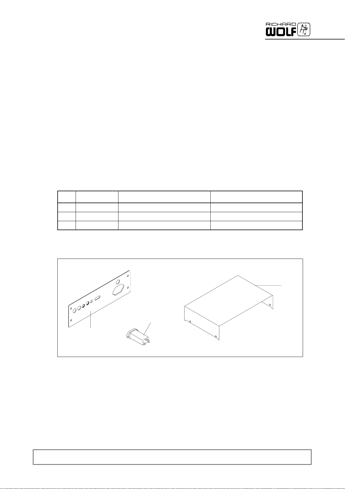
Explosionszeichnung
110
160
030
SM--5124
1
Page 6
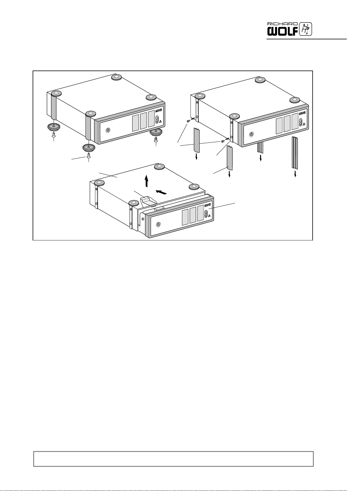
1.2 Demontage der Gehäuseabdeckung
Abb.1
1.2
1.0
Abb.3
1.8
Abb.2
1.5
1.4
1.3
b
a
1.1
-- Benötigtes Werkzeug: Kreuzschlitz--Schraubendreher.
Z Netzschalter ausschalten und das Netzkabel vom Versorgungsnetz
und dem Netzeingangsstecker trennen.
Z Verriegelungsknopf an der Geräterückwand um 180_ drehen.
Z 4 Gerätefüße (1.2) abschrauben, Abb.1.
Z Blenden (1.3) von der Halteschiene (1.4) schieben, Abb.2.
Z Die 4 untersten Kreuzschrauben (1.5) entfernen, Abb.2.
Z Gehäuseabdeckung (1.0) in Pfeilrichtung (a) ziehen, bis die Federn
(1.8) frei aus der Frontplatte (1.1) ragen, Abb. 3.
Z Gehäuseabdeckung (1.0) in Pfeilrichtung (b) abheben, Abb. 3.
2
SM--5124
Page 7
2 Wartung
2.1 Wichtige Hinweise
Das Service Manual beschreibt die für das Produkt festgelegten
externen Servicemaßnahmen.
WICHTIG!
.
Zur Durchführung der Servicemaßnahmen ist die Gebrauchsanweisung
des Produktes unbedingt zu beachten.
2.2 Wartung von Gerät und Zubehör
Die Wartung und die Prüfung am Gerät soll zum Schutz des Prüfenden in
der angegebenen Reihenfolge durchgeführt werden.
Z Sichtprüfung
Z Elektrische Sicherheitsprüfung
Z Funktionsprüfung
Die im Abschnitt ”Elektrische Sicherheitsprüfung” angegebenen Prüf-und Messverfahren beziehen sich auf die Prüfung nach EN / IEC
60601--1
Alternativ kann nach DIN VDE 751 geprüft werden.
Für Grenzwerte und die Erfassung / Dokumentation von erstgemessenen
Werten ist der Betreiber selbst verantwortlich.
Nach einer Reparatur müssen alle Messwerte (Ausgangswerte) des Geräts anhand der Angaben im Service Manual geprüft und bei Abweichungen neu eingestellt werden.
VORSICHT!
Das Produkt darf nicht betrieben werden, wenn die vorgegebenen
Messwerte nicht erreicht oder die Funktionen nicht erfüllt werden.
HINWEIS!
.
Alle Wartungs-- und Prüfarbeiten an Gerät oder Zubehör müssen dokumentiert werden.
SM--5124
3
Page 8
2.3 Sichtprüfung
Benennung Durchzuführende Kontrollen
' Sicherheitsgefährdende Verschmutzung und allgemeine Sauberkeit
Gerät und Zubehör
' Mechanische Beschädigung
' Lose oder fehlende Teile
Bedienelemente
Beschriftung / Symbolik
Sicherheitsrelevante Aufschriften
(z.B. Warnhinweise)
Sicherungseinsätze
Verkabelung
E--Karten
Lampenschild (Nur Lichtquellen)
' Mechanische Funktion und Freigängigkeit
' Vollständig und gut lesbar
' Vollständig und gut lesbar
' Auf die vom Hersteller auf dem Typenschild angegebenen Werte
(Nennstrom und Abschmelzcharakteristik)
' Auf einwandfreien Zustand (Sitz, Isolation und Brüchigkeit)
' Korrosion oder andere Beschädigungen
' Vorhanden und gut lesbar
' Beschädigte Teile sofort austauschen!
2.4 Elektrische Sicherheitsprüfung nach EN / IEC 60601--1
Benennung
Schutzleiteranschluss
Ohne Netzanschlussleitung
Schutzleiteranschluss
Mit Netzanschlussleitung
Maximal zulässige
Messwerte
' ± 0,1 Ohm
' ± 0,2 Ohm
Grenzwerte nach EN / IEC 60601--1
' ± 0,1 Ohm
' ± 0,2 Ohm
Prüfbedingung:
25 A ¦ 10% , V0± 6V, t
I
mess
prüf
5sbis10s,50Hz/60Hz
Erdableitstrom
Patientenableitstrom
' ± 400 μA
' ± 10 μA
Messpunkte:
Anschlussbuchse für
Lichtleiter
Geprüft werden:
Der Widerstand zwischen Schutzleiterkontakt bzw. Schutzleiterstift im
Netzstecker und jedem anderen schutzleiterverbundenen berührbaren
metallischen Teil.
' ± 500 μA
' Normalzustand Typ BF: ± 100 μA
' Normalzustand Typ CF: ± 10 μA
Prüfbedingung:
Messanordnung (MD) und Messaufbau nach EN / IEC 60601--1
Geprüft werden:
Der Ableitstrom, der durch den Schutzleiter bzw. vom Anwendungsteil
über den Patienten zur Erde fließen kann.
4
SM--5124
Page 9
2.5 Mess-- und Hilfsmittel
Für die Durchführung der in dieser Service Manual beschriebenen Wartungs--, Reparatur-- und Testroutinen, sind nachfolgend aufgeführte Hilfs-und Messmittel unerlässlich. Vergewissern Sie sich vor einer Reparatur,
dass die Messmittel kalibriert und in einem einwandfreien Zustand sind.
Zu Beachten: Angegebene Testkonfigurationen sind ausschließlich für
Testzwecke definiert und nicht als Anwendungsempfehlung zu bewerten.
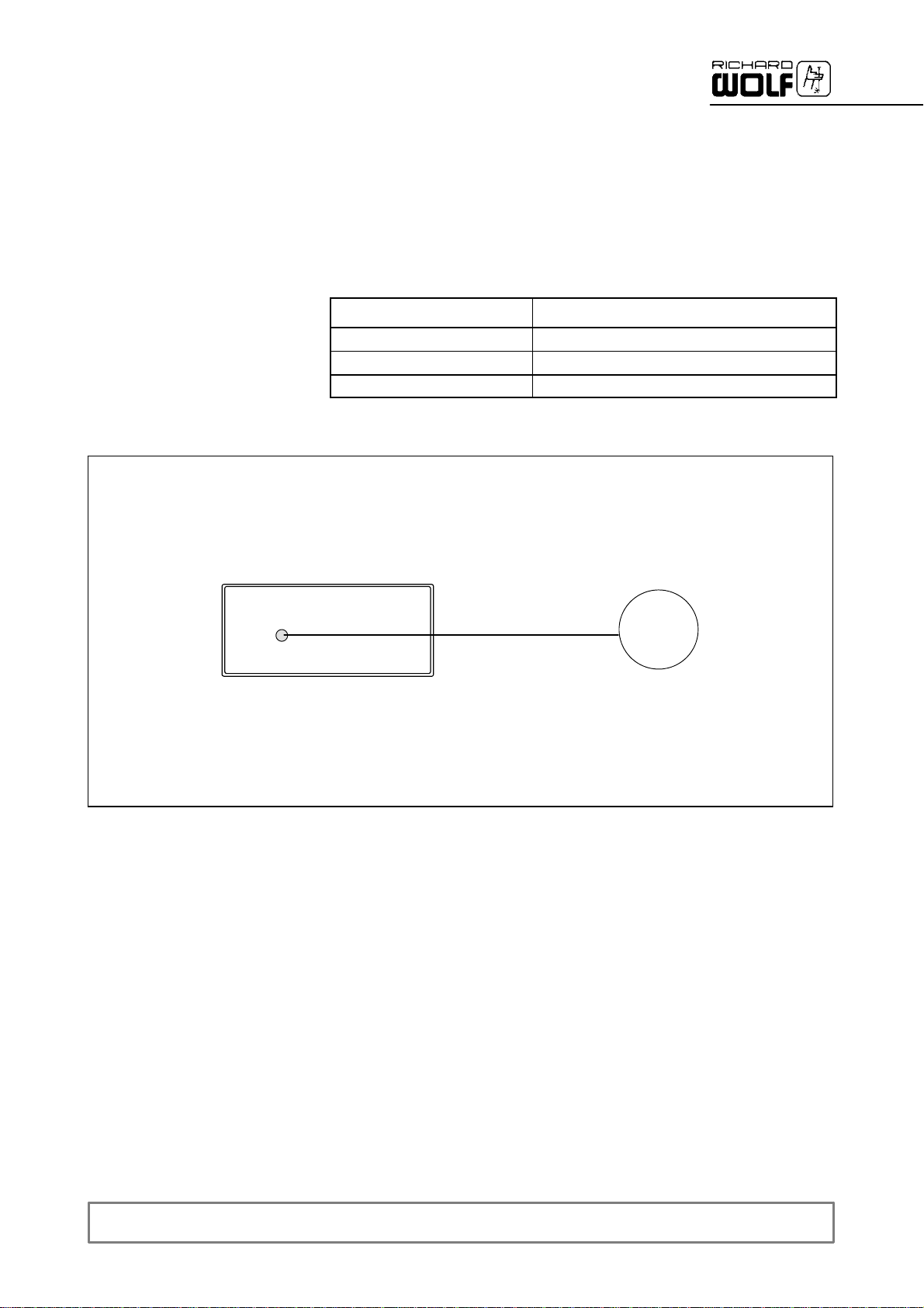
Messaufbau
Bezeichnung Zusätzliche Angaben
Effektivwert--Multimeter
Lichtleitkabel
Kugelphotometer z.B. Labsphere 3030 *
* = Das Kugelphotometer “Labsphere 3030” sollte jährlich kalibriert werden!
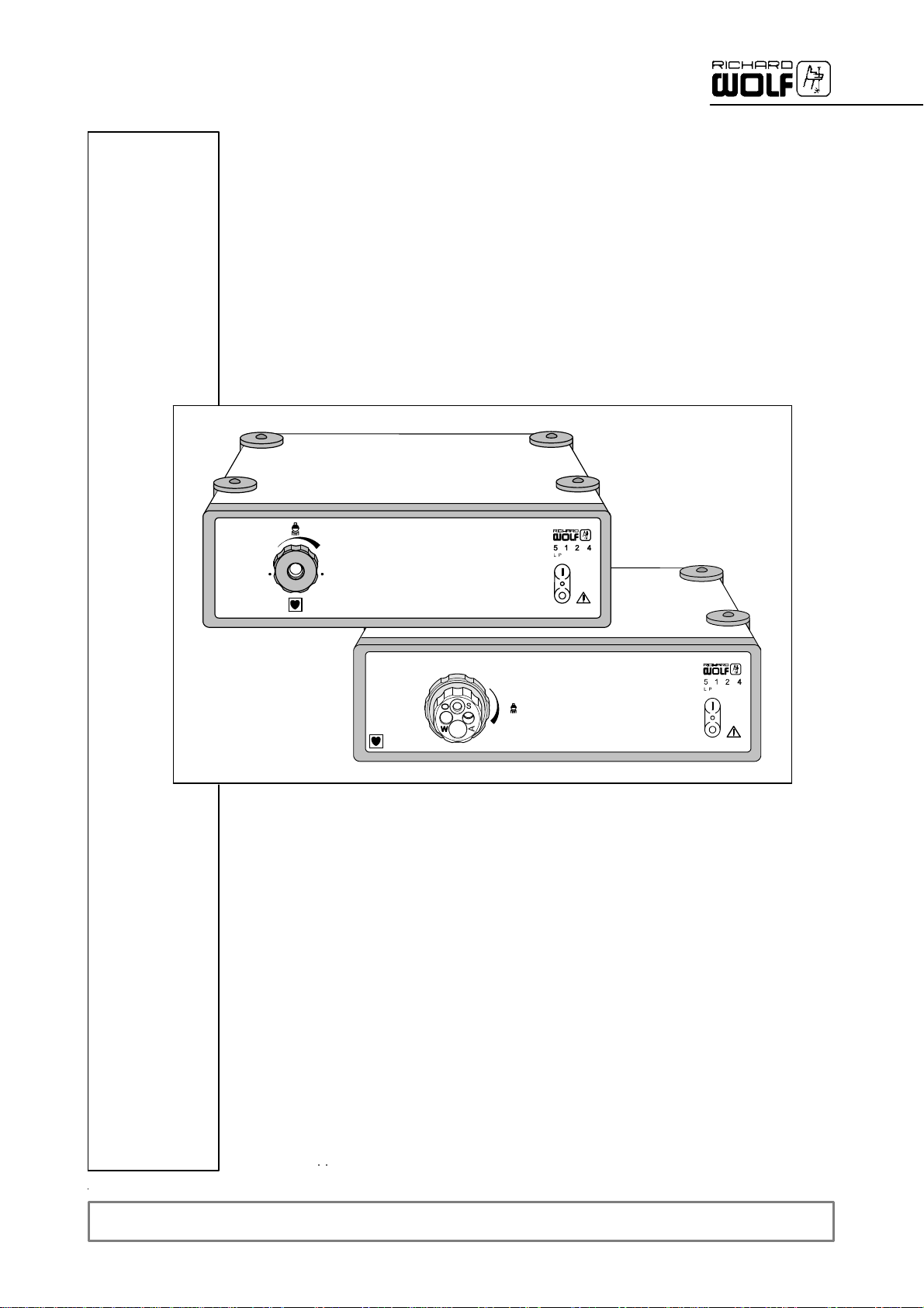
∅ 3,5 mm (8063.353)
LP 5124
Flexibler Lichtleiterl
3.0
Kugel-photometer
SM--5124
5
Page 10
2.6 Funktionsprüfung
WICHTIG!
.
Darauf achten, dass der verwendete Lichtleiter einem neuwertigen
Zustand entspricht.
Beim Einsetzen des Lampenmoduls darauf achten, dass der Glaskörper
nicht mit den Fingern berührt wird.
Benennung Prüfablauf
Es gilt der Messaufbau entsprechend Abschnitt 2.5
Gerät ans Netz anschließen
Netzschalter einschalten.
Lichtstrom Gerät einschalten. Die manuelle Helligkeitsregelung auf ,Maximum‘ (Rechtsan-
Lichtbuchsen – Blende Beim Ziehen des Lichtleitkabels wird der Strahlengang durch eine Blende
schlag) stellen. Die Lampe muss bis zur Messung mindestens 2 Minuten brennen.
Der gemessene Lichtstrom muss bei neuer Lampe mindestens 550 lm betragen. Lampe wechseln, sobald der Lichtstrom 75% des Neuwertes nicht mehr
erreicht.
Dann die manuelle Helligkeitsregelung auf ,Minimum‘ (Linksanschlag) stellen.
Der gemessene Lichtstrom darf höchstens 3% des maximalen Lichtstromes
sein.
verschlossen.
6
SM--5124
Page 11
3 Baugruppen
3.1 Schaltnetzteil (Pos. 0120 / 280)
3.1.1 Messpunkte und Versorgungsspannungen
Z Eingangsspannung:
' Entsprechend Typenschild
Z Stecker X1/X2: Netzeingang
Z Stecker X4: Minuspol Lampe
Z Stecker X7: Pluspol Lampe, am Zündgerät Vorsicht Hochspannung !
Z Stecker X17: Pin 1: +12 + 0,4V Lüfter Front-- und Rückwand
Der achtpolige Stecker X17 befindet sich an der oberen E--Karte des
Schaltnetzteils.
3.1.2 Demontage und Montage der Baugruppe
Z Komplette Baugruppe tauschen.
3.1.3 Einstellungen
Beim Baugruppentausch sind keine Einstellungen vorzunehmen.
3.1.4 Funktionsprüfungen
Z Siehe Funktionsprüfungen (Abschnitt 2.6).
Pin 2: +12 +
Pin 3: GND
Pin 4: GND
Pin 5: +12 +
Pin 6: Signal Thermoschalter
Pin 7: N.C.
Pin 8: N.C.
0,4V Thermoschalter
0,4V Lüfter Schaltnetzteil
Vorsicht Hochspannung !
3.2 Netzfilter E--Karte (Pos. 0090)
3.2.1 Demontage und Montage der Bedien--E--Karte
Z Komplette Baugruppe tauschen.
3.2.2 Einstellungen
Z Die Karte wird voreingestellt geliefert. Kein Abgleich erforderlich.
3.2.3 Funktionsprüfungen
Z Siehe Funktionsprüfung Abschnitt 2.6.
SM--5124
7
Page 12

3.3 Bedien--E--Karte (Pos. 0200)
3.3.1 Demontage und Montage der E--Karte
Z Frontrahmen ausbauen und komplette Baugruppe tauschen.
3.3.2 Einstellungen
Z Die Karte wird voreingestellt geliefert. Kein Abgleich erforderlich.
3.3.3 Funktionsprüfungen
Z Siehe Funktionsprüfungen
3.4 Blendenaufnahme kpl. (Pos. 0160)
3.4.1 Demontage und Montage der Blendenaufnahme
Z Komplette Baugruppe tauschen.
Z Isolierteil Lichtbuchse (Pos. 330) auf Minimum stellen.
' Blendenaufnahme nun so positionieren, daß die Öffnung zum opti-
schen System zu 50% abgedeckt ist (siehe Abbildung )
Abschnitt 2.6.
3.4.2 Funktionsprüfungen
8
Z Siehe Funktionsprüfungen
Abschnitt 2.6.
SM--5124
Page 13

ENGLISH
0
SM--5124
Page 14

Contents
1 General information 1.......................................................
1.1 Ordering spare parts 1........................................................
1.2 Disassembly of housing cover 2................................................
2 Maintenance 3..............................................................
2.1 Important notes 3............................................................
2.2 Maintenance of device and accessories 3.......................................
2.3 Visual check 4...............................................................
2.4 Electrical safety test to EN / IEC 60601--1 4.....................................
2.5 Measuring instrumentation and other equipment 5................................
2.6 Function check 6.............................................................
3 Modules 7..................................................................
3.1 Switching power supply (item 0120 / 280) 7......................................
3.1.1 Measuring points and supply voltages 7.........................................
3.1.2 Disassembly and assembly of module 7.........................................
3.1.3 Settings 7...................................................................
3.1.4 Function checks 7............................................................
3.2 Mains/line filter PCB (item 0090) 7.............................................
3.2.1 Disassembly and assembly of control PCB 7....................................
3.2.2 Settings 7...................................................................
3.2.3 Function checks 7............................................................
3.3 Control PCB (item 0200) 8....................................................
3.3.1 Disassembly and assembly of PCB 8...........................................
3.3.2 Settings 8...................................................................
3.3.3 Function checks 8............................................................
3.4 Diaphragm holder, complete (item 0160) 8.......................................
3.4.1 Disassembly and assembly of diaphragm holder 8................................
3.4.2 Function checks 8............................................................
4 Anhang /Annex 9...........................................................
4.1 Reparaturteile (Standard) / Repair parts (standard) 9.............................
4.1.1 Explosionszeichnung Gerät / Exploded view Device 10.............................
4.1.2 Explosionszeichnung Frontrahmen kpl. / Exploded view Front frame cpl. 1 1...........
4.2 Reparaturteile (Universal--Lichtanschlussbuchse) /
Repair parts (universal light socket) 12...........................................
4.2.1 Explosionszeichnung Gerät / Exploded view Device 13.............................
4.2.2 Explosionszeichnung Frontrahmen kpl. / Exploded view Front frame cpl. 14...........
4.4 Verdrahtungsplan / Wiring diagram 15...........................................
4.5 Lageplan Netzfilter E--Karte / Component drawing Power Filter PCB
(Pos. 0090) 16................................................................
4.6 Lageplan Bedien--E--Karte / Component drawing Control PCB (Pos. 0200) 17.........
5 Protokolle / Reports 18.......................................................
5.1 Prüfprotokoll / Test Report 18...................................................
5.2 Wartungsprotokoll / Maintenance report 19.......................................
SM--5124
I
Page 15

1 General information
1.1 Ordering spare parts
The part number required for ordering a spare part is listed in the repair
parts list under the item number used in the service manual.
IMPORTANT!
.
Specify the following numbers when ordering spare parts:
D Part number of the spare part.
D Model/type number of the device.
D Serial number of the device.
Example
Repair parts list
Pos. Type / Model Bezeichnung Designation
0030 72 311.112 Kaltgeräteeinbaubuchse Mains socket
0110 64 117.102 Rückwand Back plate
0160 64 291.022 Gehäusedeckel beschichtet Top cover epoxy coated
Exploded view
110
160
030
SM--5124
1
Page 16

1.2 Disassembly of housing cover
fig.1
1.2
1.0
fig.3
1.8
fig.2
1.5
1.4
1.3
b
a
1.1
-- The following tools are required: Philips screwdriver.
Z Switch off the power switch and disconnect the power cable from the
wall socket and from the power input connector of the device.
Z Turn the locking knob on the rear panel of the device 180_.
Z Unscrew the four feet (1.2), fig.1.
Z Slide trim plates (1.3) off the rails (1.4), fig.2.
Z Remove the lower four philips screws (1.5), fig.2.
Z Pull housing cover (1.10) in direction of arrow (a) until the tongues
(1.8) are disengaged from the front panel (1.1) fig. 3.
Z Lift off housing cover (1.0) in direction of arrow ( b), fig. 3.
2
SM--5124
Page 17

2 Maintenance
2.1 Important notes
This Service Manual describes the external service measures defined for
the product.
IMPORTANT!
.
For carrying out the service measures the product instruction manual
must be observed.
2.2 Maintenance of device and accessories
To protect the technician who carries out the test, the maintenance jobs
and tests must be carried out in the order specified below.
Z Visusal check
Z Electrical safety test
Z Functional check
The test and measuring procedures specified in the chapter ”Electrical
Safety Test” relate to the test in accordance with EN / IEC 60601--1.
Alternatively, the electrical safety test can be carried out in accordance
with DIN 751.
The operator shall bear responsibility for the limit values and collection /
documentation of output values measured.
After repair all measurement values (specified output values) of the device must be checked as described in the Service Manual, and readjusted
if deviations are observed.
CAUTION!
Do not use this product if the specified measurement values or
functions are not fulfilled.
NOTE!
.
Any maintenance or testing job on the device or accessories must be
documented.
SM--5124
3
Page 18

2.3 Visual check
Item to be checked Check for
' Safety--relevant soiling / contamination and general cleanliness.
Device and accessories
' Mechanical damage
' Loose or missing parts
Controls
Lettering / Symbols
Safety--relevant labeling
(e.g warnings)
Device fuses
Cables
PCBs/cards
Lamp plate (light sources only)
' Mechanical function and easy operation
' Completeness and legibility
' Completeness and legibility
' the values specified by the manufacturer on the identification plate
(Nominal current and melting characteristics)
' for perfect condition (position, insulation and brittleness)
' Corrosion or other damage
' in place and easy to read
' Replace damaged parts immediately
2.4 Electrical safety test to EN / IEC 60601--1
Designation
Protective earth
connector
Without power cable
Protective earth
connector
With power cable
Maximum permissible
values
' ± 0.1 Ohm
' ± 0.2 Ohm
Limit values to EN / IEC 60601--1
' ± 0.1 Ohm
' ± 0.2 Ohm
Test conditions:
25 A ¦ 10% , V0± 6V,t
I
meas
Test for:
The resistance between protective earth connector and protective earth
contact in the power plug and any exposed metal part connected to the
protective earth connector.
5 s to 10 s , 50 Hz / 60 Hz
test
Earth/ground leakage
current
Patient leakage current
4
' ± 400 μA
' ± 10 μA
Measuring points:
Light cable connection
socket
' ± 500 μA
' Normal condition Type BF: ± 100 μA
' Normal condition Type CF: ± 10 μA
Test conditions:
Measurement layout (MD) and measurement setup to EN / IEC 60601--1
Test for:
The leakage current which can flow through the protective earth/ground
connector or from the applied part via the patient to earth/ground.
SM--5124
Page 19

2.5 Measuring instrumentation and other equipment
The measuring devices and other equipment listed below are essential
for carrying out the maintenance, repair and test routines described in
this service manual. Make sure that the measuring devices have been
calibrated and are in perfect condition before carrying out any repairs.
Please observe the following: The test specifications specified were definded exclusively for test purposes and are not a recommendation for use.
Designation Additional information
Multimeter true RMS
Light cable
Spherical photometer e.g. Labsphere 3030 *
* = Spherical photometer “Labsphere 3030” should be calibrated once a year!
Measurement setup
∅ 3.5 mm (8063.353)
LP 5124
Flexible light cable
3.0
Spherical
photometer
SM--5124
5
Page 20

2.6 Function check
IMPORTANT!
.
Make sure that the light cables used are in an ”as--new” condition.
When installing the lamp module make sure you do not touch the glass
bulb with your bare fingers.
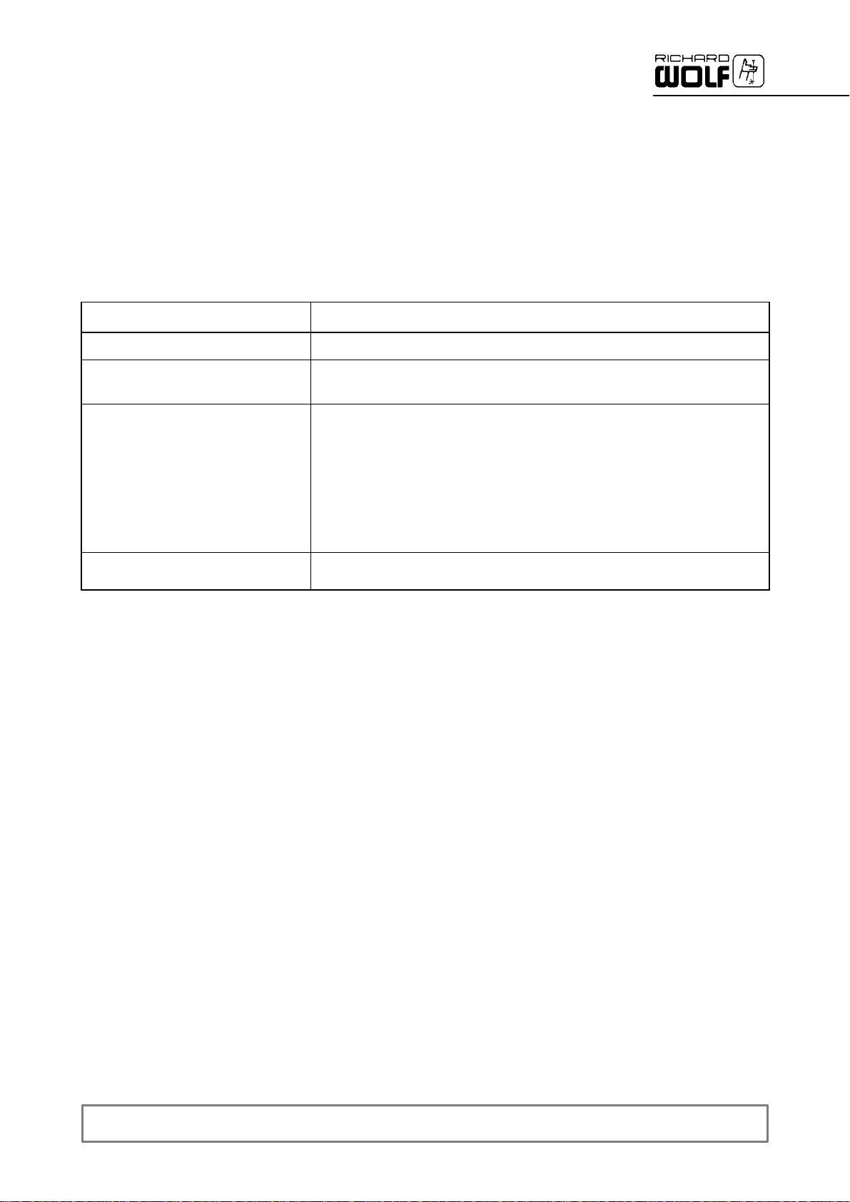
Designation Test procedure
The measurement setup corresponding to section 2.5 is valid
Connect the device to mains/power supply
Switch on the power switch.
Light intensity Switch on device. Set manual brightness control to ,maximum‘ (right hand
Light socket – diaphragm When disconnecting the light cable, a diaphragm closes the beam path.
stop). For measurement purposes the lamp must have been on for at least two
minutes.
The light intensity measured must be at least 550 lm for a new lamp. Replace
lamp if the light intensity won’t reach 75% of the new intesity value.
Then set the manual brightness control to ,minimum‘ (left hand stop). The
measured light intesity must be no more than 3% of the maximum light intesity.
6
SM--5124
Page 21

3 Modules
3.1 Switching power supply (item 0120 / 280)
3.1.1 Measuring points and supply voltages
Z Input voltages:
' As specified on identification plate
Z Plug X1/X2: Power input
Z Plug X4: Minus pole lamp
Z Plug X7: Plus pole lamp, to ignition/starter device Caution high voltage !
Z Plug X17: Pin 1: +12 + 0.4V Fan front and rear panel
The 8--pole plug X17 is located at the upper PCB of the power supply.
3.1.2 Disassembly and assembly of module
Z Replace complete module.
3.1.3 Settings
When the module is replaced, no settings are required.
3.1.4 Function checks
Z see function checks (section 2.6).
Caution high voltage!
Pin 2: +12 +
Pin 3: GND
Pin 4: GND
Pin 5: +12 +
Pin 6: Thermo switch signal
Pin 7: N.C.
Pin 8: N.C.
0.4V thermo switch
0.4V Fan for switching power supply
3.2 Mains/line filter PCB (item 0090)
3.2.1 Disassembly and assembly of control PCB
Z Replace complete PCB.
3.2.2 Settings
Z The PCB is supplied in preset condition. No adjustments are neces-
sary.
3.2.3 Function checks
Z See function checks section 2.6.
SM--5124
7
Page 22

3.3 Control PCB (item 0200)
3.3.1 Disassembly and assembly of PCB
Z Remove front frame and replace complete module.
3.3.2 Settings
Z PCB is delivered in preset condition. No adjustments are necessary.
3.3.3 Function checks
Z see function checks
section 2.6.
3.4 Diaphragm holder, complete (item 0160)
3.4.1 Disassembly and assembly of diaphragm holder
Z Replace complete module.
Z Set insulating part of light socket (item 330) to minimum.
' Position diaphragm holder in such a way that it covers 50% of the
opening to the optical system (see figure).
3.4.2 Function checks
8
Z see function checks
section 2.6.
SM--5124
Page 23

4 Anhang /Annex
4.1 Reparaturteile (Standard) / Repair parts (standard)
Pos. Type / Model Bezeichnung Designation
0010 64 070.604 Gerätefuß kpl. Equipment foot, cpl.
0020 64 214.027 Lüfter, kpl. (Rückwand) Fan, cpl. (backplate)
0040 64 031.277 Lampenhalter Lamp holder
0060 72 316.276 Thermoschalter, 80 C +-- 3 Thermal switch, 80 C +-- 3
0070 64 214.025 Lüfter, kpl. (Front) Fan, cpl. (front)
0080 72 323.138 Potentialausgleichsstecker Socket for potential equalization
0090 64 351.853 Netzfilter E--Karte Power filter PCB
0100 72 311.095 Funkentstörfilter mit Kaltgerätestecker Radio suppressor with mains socket
0120 72 321.676 Schaltnetzteil (180W) Switching power supply (180W)
0130 64 086.028 Drehknopf Rotary knob
0140 64 211.089 Frontrahmen, kpl. montiert mit Lichteinheit Front frame, cpl. mounts with light unit
0145 64 159.790 Frontplattenfolie Front plate foil
0150 64 110.377 Zahnrad Gear wheel
0160 64 126.019 Blendenaufnahme, kpl. mit Blende Diaphragm holder cpl. with diaphragm
0170 74 016.006 Linse, asphärisch Lens, aspherical
0180 64 198.003 Linsenhalter Lens holder
0190 64 127.097 Lichtblende Light shield
0200 64 352.019 Bedien E--Karte Control PCB
0220 64 011.233 Abdeckplatte, von vorne links Cover plate, in front left
0230 64 005.950 Abdeckplatte, von vorne rechts Cover plate, in front right
0240 64 010.067 Gehäusedeckel, kpl. Top cover, cpl.
0250 64 127.066 Blende, Gehäuse Shield, housing
0260 64 010.024 Deckel kpl. Cover cpl.
0270 64 204.166 Halteschiene Support bar
0280 72 321.676A Schaltnetzteil (180W) (A)* Switching power supply (180W) (A)*
0290 72 321.406 Zündgerät (in Pos. 120 / 280 enthalten) Ignition unit (incl. in pos. 120 / 280)
0300 64 214.029 Lüfter Schaltnetzteil Fan switching power supply
0310 64 320.939 HV--Kabelbaum HV--wiring harness
0320 64 211.087 Frontrahmen kpl. Front frame cpl.
0330 64 290.081 Isolierteil Insulating part
0340 64 181.030 Lagerplatte Base plate
0350 64 013.166 Bolzen Bolt
0360 64 026.151 Lichtbuchse Light socket
0370 15 042.600 Rastschraube Stop screw
0380 64 064.308 Abstandshülse Spacer tube
0390 14 002.215 IR--Filter IR--Filter
0400 14 001.456 Schutzglas Protective glass
0410 64 096.086 Schraube, Schutzglas Screw, protective glass
* = (A) : Reparaturaustausch, nur gegen Einsendung der defekten Baugruppe /
' Positionsnummern siehe Explosionszeichnung
' For position numbers see exploded view
Repair exchange, only available by sending in the defective module
SM--5124
9
Page 24

4.1.1 Explosionszeichnung Gerät / Exploded view Device
0240
0260
0270
0010
0250
0230
0220
0040
0020
0100 0080
0130
YE 6
YE 2
RD 5
BU 4
BK 3
0310
0090
RD 1
0300
0290
0120 /
0280
10
0410
0400
0070
0060
2
3
BK--RD1
0200
SM--5124
Page 25

4.1.2 Explosionszeichnung Frontrahmen kpl. / Exploded view Front frame cpl.
Frontrahmen komplett montiert mit Lichteinheit /
Front frame complete mounts with Light unit (Pos. 0140)
0180
0160
0390
0380
0170
0360
0370
0350
0190
0150
0320
0330
0340
0145
SM--5124
11
Page 26

4.2 Reparaturteile (Universal--Lichtanschlussbuchse) /
Repair parts (universal light socket)
Pos. Type / Model Bezeichnung Designation
0010 64 070.604 Gerätefuß kpl. Equipment foot, cpl.
0020 64 214.027 Lüfter, kpl. (Rückwand) Fan, cpl. (backplate)
0040 64 031.277 Lampenhalter Lamp holder
0060 72 316.276 Thermoschalter, 80 C +-- 3 Thermal switch, 80 C +-- 3
0070 64 214.025 Lüfter, kpl. (Front) Fan, cpl. (front)
0080 72 323.138 Potentialausgleichsstecker Socket for potential equalization
0090 64 351.853 Netzfilter E--Karte Power filter PCB
0100 72 311.095 Funkentstörfilter mit Kaltgerätestecker Radio suppressor with mains socket
0120 72 321.676 Schaltnetzteil (180W) Switching power supply (180W)
0130 64 086.028 Drehknopf Rotary knob
0140 64 211.105 Frontrahmen, kpl. montiert mit Lichteinheit Front frame, cpl. mounts with light unit
0145 64 159.842 Frontplattenfolie Front plate foil
0150 64 050.029 Zahnrad Gear wheel
0160 64 126.019 Blendenaufnahme, kpl. mit Blende Diaphragm holder cpl. with diaphragm
0170 74 016.006 Linse, asphärisch Lens, aspherical
0180 64 198.003 Linsenhalter Lens holder
0190 64 050.030 Zahnrad Gear wheel
0200 64 352.019 Bedien E--Karte Control PCB
0220 64 011.233 Abdeckplatte, von vorne links Cover plate, in front left
0230 64 005.950 Abdeckplatte, von vorne rechts Cover plate, in front right
0240 64 010.067 Gehäusedeckel, kpl. Top cover, cpl.
0250 64 127.066 Blende, Gehäuse Shield, housing
0260 64 010.024 Deckel kpl. Cover cpl.
0270 64 204.166 Halteschiene Support bar
0280 72 321.676A Schaltnetzteil (180W) (A)* Switching power supply (180W) (A)*
0290 72 321.406 Zündgerät (in Pos. 120 / 280 enthalten) Ignition unit (incl. in pos. 120 / 280)
0300 64 214.029 Lüfter Schaltnetzteil Fan switching power supply
0310 64 320.939 HV--Kabelbaum HV--wiring harness
0320 64 211.104 Frontrahmen kpl. Front frame cpl.
0330 64 078.154 Isolierteil Insulating part
0340 73 217.001 Schraube Bolt
0350 64 013.179 Bolzen Bolt
0360 64 025.027 Lichtbuchse Light socket
0370 64 096.094 Rastschraube Stop screw
0380 64 064.308 Abstandshülse Spacer tube
0390 14 002.215 IR--Filter IR--Filter
0400 14 001.456 Schutzglas Protective glass
0410 64 096.086 Schraube, Schutzglas Screw, protective glass
0420 64 064.381 Lagerhülse Bearing sleeve
0430 64 038.941 Führungsblech Guiding plate
* = (A) : Reparaturaustausch, nur gegen Einsendung der defekten Baugruppe /
Repair exchange, only available by sending in the defective module
12
' Positionsnummern siehe Explosionszeichnung / ' For position numbers see exploded view
SM--5124
Page 27

4.2.1 Explosionszeichnung Gerät / Exploded view Device
0240
0260
0270
0010
0250
0230
0220
0040
0020
0100 0080
0130
YE 6
RD 5
BK 3
BU 4
0310
0090
YE 2
RD 1
0300
0290
0120 /
0280
0410
SM--5124
0400
0070
0060
2
3
BK--RD1
0200
13
Page 28

4.2.2 Explosionszeichnung Frontrahmen kpl. / Exploded view Front frame cpl.
Frontrahmen komplett montiert mit Lichteinheit /
Front frame complete mounts with Light unit (Pos. 0140)
0160
0180
0390
0380
0170
0420
0370
0430
0350
0190
0320
0150
0145
14
0330
0360
SM--5124
Page 29

4.3 Verdrahtungsplan / Wiring diagram
0070
Lüfter, Front
fan, front
0060
0020
Lüfter, Rückwand
fan, backplate
0120 (280)
0100
0090
0300
0200
Lüfter, Schaltnetzteil
fan, switching power supply
SM--5124
15
Page 30

4.4 Lageplan Netzfilter E--Karte / Component drawing Power Filter PCB
(Pos. 0090)
X2
C1
Richard Wolf GmbH.
R1
X1
L1
PCB PM 09/96
16
64151.853
R2
C4
C3
X3
Line in
C2
X4
Line in
SM--5124
Page 31

4.5 Lageplan Bedien--E--Karte / Component drawing Control PCB (Pos. 0200)
S2
ON OFF
BS
X1
X2 X3
X4
X8
R12
X10
X9
X11
R11
SM--5124
17
Page 32

5 Protokolle / Reports
5.1 Prüfprotokoll / Test Report
Betreiber / User: ..................................................................... Typen Nr. / Type No.: ..............................
Anschrift / Address: ...................................................................................................................................
Durchgeführte Prüfung
Test carried out
Serien Nr.
Serial No.
Datum
Date
Name / Unterschrift
Name / Signature
18
SM--5124
Page 33

5.2 Wartungsprotokoll / Maintenance report
Betreiber / User: .................................................................... Typen Nr. / Type No.: ..............................
Anschrift / Address: .................................................................................................................................
Wartungsmaßnahmen
Servicing check up
Serien Nr.
Serial No.
Datum
Date
Name / Unterschrift
Name / Signature
SM--5124
19
Page 34

GERMANY
RICHARD WOLF GmbH
75438 Knittlingen
Pforzheimerstr. 32
Telephone: +49 70 43 35--0
Telefax: +49704335--300
MANUFACTURER
info@richard--wolf.com
www.richard--wolf.com
USA
RICHARD WOLF
Medical Instruments Corp.
353 Corporate Woods Parkway
Vernon Hills, Illinois 60061
Telephone: +1 84 79 13 11 13
Telefax: +1 84 79 13 14 88
sales&marketing@richardwolfusa.com
www.richardwolfusa.com
UK
RICHARD WOLF UK Ltd.
Waterside Way
Wimbledon
SW17 0HB
Telephone: + 44 20 89 44 74 47
Telefax: +442089441311
admin@richardwolf.uk.com
www.richardwolf.uk.com
FRANCE
RICHARD WOLF France S.A.R.L.
Rue Daniel Berger
Z.A.C. La Neuvillette
51100Reims
Telephone: +33 3 26 87 02 89
Telefax: +33326876033
endoscopes@richardwolf.fr
Marketing Office
U.A.E
RICHARD WOLF Middle East
P.O. Box 500283
AL Thuraya Tower1
th
Floor,
9
Room 904, Dubai
Telephone: + 9 71 43 68 19 20
Telefax: + 9 71 43 68 61 12
middle.east@richard--wolf.com
www.richard--wolf.com
BELGIUM / NETHERLANDS
N.V. Endoscopie
RICHARD WOLF Belgium S.A.
Industriezone Drongen
Landegemstraat 6
9031 Gent Drongen
Telephone: +32 92 80 81 00
Telefax: +3292829216
endoscopy@richard--wolf.be
www.richard--wolf.be
AUSTRIA
RICHARD WOLF Austria
Ges.m.b.H.
Wilhelminenstraße 93 a
1160Vienna
Telephone: +43 14 05 51 51
Telefax: +431405515145
info@richard--wolf.at
www.richard--wolf.at
INDIA
RICHARD WOLF India Private Ltd.
JMD Pacific Square
No. 211 A, Second Floor
Behind 32
Gurgaon -- 122 001
National Capitol Region
Telephone: + 91 12 44 31 57 00
Telefax: +911244315705
india@richard--wolf.com
www.richard--wolf.com
nd
Milestone
20
SM--5124
 Loading...