

Page 1
Operation and
Maintenance Instructions
Unit Heaters LH
(Translation of the original)
N° d’art. : 3040531_0711 Subject to modications
GB
Wolf GmbH · Postfach 1380 · 84048 Mainburg · Tél. 08751/74-0 · Fax 08751/741600 · Internet : www.wolf-heiztechnik.de
Page 2

3040531_07112
Index
General ....................................................................................................................... 3
Symbols ...................................................................................................................... 3
Safety instructions ...................................................................................................... 4
Standards and regulations.......................................................................................... 4
Unit description ........................................................................................................... 4
Installation and operation instructions ........................................................................ 5
Prior to the installation ........................................................................................... 6 - 7
Installation instructions ........................................................................................ 8 - 10
Electrical connection..................................................................................................11
Switches ............................................................................................................ 12 - 14
Control devices for damper actuators....................................................................... 15
Thermostats.............................................................................................................. 16
Control system WRS ........................................................................................... 17-20
Actuators .................................................................................................................. 21
Push-button .............................................................................................................. 21
Intermediate terminal box ......................................................................................... 22
Maintenance ............................................................................................................. 23
Frost protection......................................................................................................... 23
Hydraulic adaption of unit heaters within a group..................................................... 24
Rain protection hood and roof lead-in box.......................................................... 25- 26
Notes ........................................................................................................................ 27
Index
Page 3
3040531_0711 3
General
The present operation and maintenance instructions are exclusively applicable for Wolf
unit heaters LH.
Read these instructions carefully prior to the installation.
These instructions, as a part of the unit, have to be kept accessible.
No warranty claims will be accepted if operation and maintenance instructions are not
adhered to.
Symbols
The following symbols are used in these instructions. These important instructions
concern personal safety, as well as technical reliability.
"Safety instructions" are instructions with which you must comply exactly, to
prevent injury and material losses.
Danger through "live" electrical components.
Never touch electrical components or contacts when the ON/OFF switch is in
the ON position.
This creates a risk of electrocution, which may cause injury or death.
"Attention" indicates technical instructions which you must observe, to prevent
material losses and unit malfunctions.
In addition to the operation and maintenance instructions there are as well stick-on
labels on the unit, which have to be adhered to in the same manner.
Attention :
General / Symbols
Page 4
3040531_07114
Safety instructions
Installation, commissioning, service and operation may only be carried out by qualied
personnel.
For electrical installations VDE regulations and local guidelines have to be adhered to.
The unit may only be operated within the capacity range indicated in the technical
documents of Messrs. Wolf.
The unit may only be applied for purposes of ventilation. It is ony suitable for air. The
air must not contain any hazardous, combustible, explosive, aggressive, corrosion
developing or any other dangerous substances.
The unit may only be operated in technically perfect condition. Any malfunction or damage
which may inuence the safety or perfect function of the unit have to be eliminated by
a recognized specialist, at once.
Damaged unit components may only be replaced by original Wolf - spare parts.
Only qualied electricians are allowed to perform work on electrical appliances or components, adhering to the electric regulations.
It is not allowed to work in the direct vicinity of a running fan. There is a risk of being
hurt by the running fan.
Before undertaking maintenance work, always ensure that the system main isolator /
the repair switch(es) are OFF and locked to prevent unintentional reactivation.
Safety Instructions / Standards,
Regulations / Unit Description
Wolf unit heaters consist of a zinc plated sheet steel casing. The casing is composed
of a self-supporting pentapost prole construction, which is welded and zinc plated, and
of zinc plated lateral casing panels.
The casing is provided with a LPHW-heating coil which consists either of copper tubes
and aluminium ns or galvanized, nned steel tubes.
The air inlet is provided with a unit consisting of an axial fan-motor-protection grille assembly which takes the air in via the air inlet in the rear panel. While passing the heat
exchanger on the discharge side the air is heated. The warm airstream may be turned
downwards via an adjustable discharge louvre.
General unit
description and design
Standards, Regulations
The following standards and regulations apply to the LH unit heaters:
- Machine directive 2006/42/EU
- Low voltage directive 2006/95/EU
- EMC directive 2004/108/EU
- DIN EN 12100 Safety of machines; general design principles
- DIN EN 13857 Safety of machines; safety distances
- DIN EN 349 Safety of machines; minimum distances
- DIN EN 953 Safety of machines; guards
- DIN EN 60204-1 Safety of machines; electric equipment
For the installation and maintenance, the following regulations and safety instructions have to be adhered to:
- DIN VDE 0100 Requirements for high voltage installations up to 1000 V
- DIN VDE 0105 Operation of high voltage installations, general restrictions
- DIN VDE 0701-0702 Repair, modication and testing of electrical appliances
Page 5
3040531_0711 5
Motors
LH-three-phase motors (except explosion proof motors) may either operate on low spped
Y or on high speed ∆. The motor windings are designed accordingly.
Motors for single-phase alternating current may only oberate on high or low speed
depending on delivery.
LH-single-phase and three-phase motors (except explosion proof motors) are protected
with thermal cutours, which interrupt the control circuit of switch or step switch in case
of overheating of the fan motor.
When temperature decreases, the motor switches on automatically.
The winding protection wirks only in case of switching the therminal cutouts to the control
circuit of a switch of step switch.
Using switches or speed controllers not delivered by Wolf, we can´t take any
warranty!
Attention :
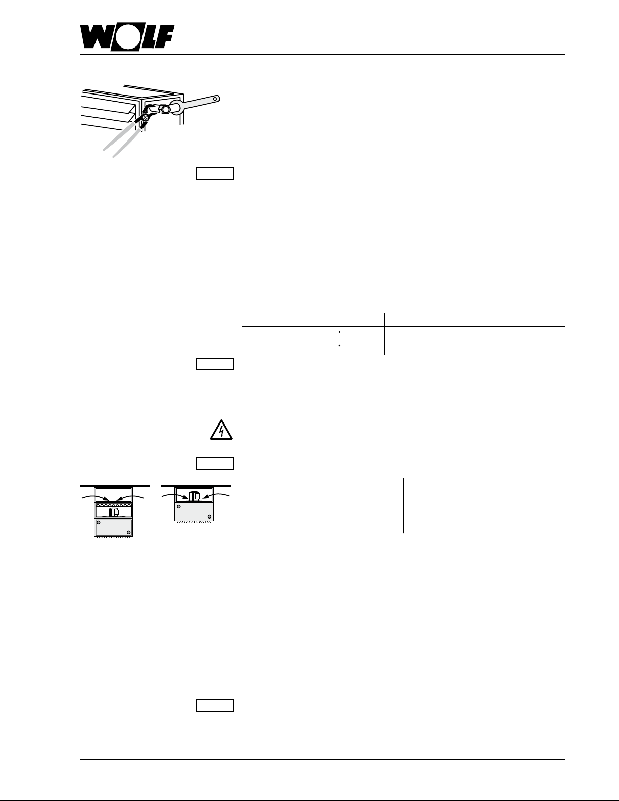
Heat exchanger
When connecting the heat exchanger counterhold with pipe-wrench.
The ow of the heating system has to be connected on the air discharge side of the
heat exchanger.
For steam:
Steam connection on top
Condensate return on bottom of discharge side
Connections on left hand side only, in direction of air ow
Evacuation of air and uid has to be provided on site!
Operation limits for LPHW/MPHW:
Heat exchanger Co./Al., type 1, 2, 3, 4, NP 16, up to 140°C (threaded sleeves)
Heat exchanger steel-galvanized, NP 10, up to 140°C (threaded sleeves)
Heat exchanger steel-galvanized, NP 10, up to 180°C (welded anges)
Operation limits for steam:
Heat exchanger Co./Al., type D, up to 9 bar saturated steam
Heat exchanger Co./Al., upt to 9 bar saturated steam
Attention :
In ceiling-mounted units there may occur damages by overheating when motor is swiched
off. For this reason the water inlet temperature has to be limited on:
Motor for higher surrounding temp. (on
request)
115°C when additional sections are
mounted (1)
140°C when additional sections are
mounted (2)
140°C without additional selections (2) 180°C without additional sections (2)
When fan stops all control valves have to be closed automatically.
Attention :
Ceiling-mounted unit
(1)
(2)
Installation and Operation Instructions
Electric heater
To avoid overheating, pay atenteion to the following minimum air volumes:
LH 25 40 63 100
Luftrichtung horizontal
V
min [m³/h] 800 1600 2500 4000
Luftrichtung vertikal
V
min [m³/h] 1000 2200 3200 5000
Protective measures: In any case it has to be secured that the electric heater is switched off when the air volume is falling below the indicated minimum. Additionally, the
electric heater may only be set into oberation by one or several magnetic swiches
whose control circuit leads over the automatic overheating controllers wired in line. Pay
attention to the fact that at least one automatic controller has to be mounted on top of
the electric heater.
In any case, protect against water
Attention :
Page 6
3040531_07116
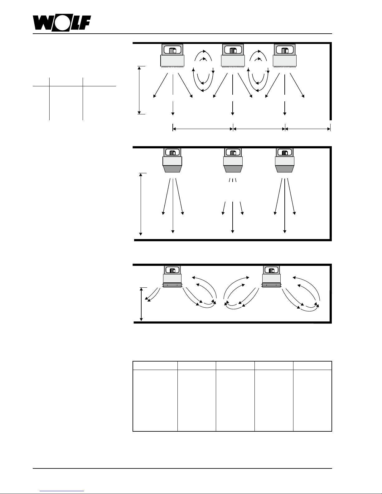
Clearances
Clearances for LH ceiling unit or wall
unit in metres
LH LH to LH LH to wall
25 7 - 9 3 - 4
40 9 - 11 3 - 5
63 11 - 13 4 - 6
100 13 - 15 5 - 7
Discharge accessories
referring to a.m. spacing, a ∆t air (= t discharge - t room) of approx. 25K and high
speed.
LH 25 40 63 100
Spacing:
Discharge/Floor
up to 2,5 m 4-side-discharge 4-side-discharge 4-side-discharge 4-side-discharge
3-4 m Wide spread
discharge
Wide spread
discharge
Wide spread
discharge
Wide spread
discharge
4-5 m Cone Cone Louvre Wide spread
5-6 m Cone Cone Cone Louvre
à partir de 6 m Cone Cone Cone Cone
If the temperature difference ∆t air exceeds 30K the above selection table is no longer
applicable, because of the reduced penetration.
Prior to the Installation
7-15m 7-15m 3-7m
Air throw
Spacing Spacing Spacing
Primary air Primary air
Larger throw for very
high rooms by means of
discharge cone
Four-side discharge for lower rooms
Secondary
vortex
Secondary
vortex
Primary air
larger throw
by approx. 25%
up to 2,5 m max.
Page 7
3040531_0711 7
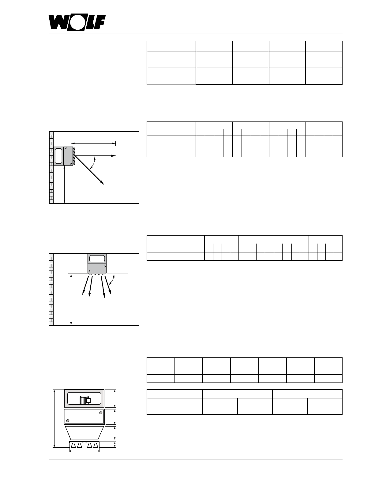
Prior to the Installation
Clearances
Clearances for wall-mounted units
and clearances for ceiling-mounted
units, vanes vertical.
Ceiling-mounted unit,
vanes deected.
LH 25 40 63 100
LH from LH
LH to wall
7 - 9m
3 - 4m
9 - 11m
3 - 5m
11 - 13m
4 - 6m
13 - 15m
5 - 7m
LH from LH
LH to wall
- 12m
4 - 6m
- 14m
5 - 7m
- 16m
6 - 8m
- 18m
7 - 9m
Height wall-mounted unit with
adaption cone and induction
louvre
A
B
F
C
D
E
A B C D E F
LH 6 3 1040 120 270 300 350 460
LH 1 0 0 1130 120 320 340 350 590
LH 63 100
Type 1 2 1 2
Max. height (m) 12 11 11 10
Higher above oor heights on request.
Air throw: wall-mounted unit
LH 25 40 63 100
Type 1 2 3 4 1 2 3 4 1 2 3 4 1 2 3 4
Air throw [m]*
high speed 19 18 16 15 27 26 23 21 29 27 25 23 36 35 34 32
low speed 16 15 13 12 20 19 16 14 22 20 18 17 30 28 26 25
* Figures represent air throws on dened operating conditions.
(mixing temperature 10 K above room temperature)
Air throw m
Angle of adjustment
Speed of air stream in utility
area 0,2m/sec.
0,2 m/sec.
Height above oor
min. 2,5m
max. 4,0m
LH 25 40 63 100
Type 1 2 3 4 1 2 3 4 1 2 3 4 1 2 3 4
Height above oor [m]* 5 4,5 4 3,5 6 5,5 5 4,5 7 6,5 6 5,5 8 7,5 7 6,5
*The optimum vane angle depends on the height above oor.
Higher above oor heights on request.
Height above oor,
ceiling-mounted unit
Angle of
adjustment
Speed of air stream in utility
area 0,2m/sec.
Height above oor [m]
Page 8
3040531_07118
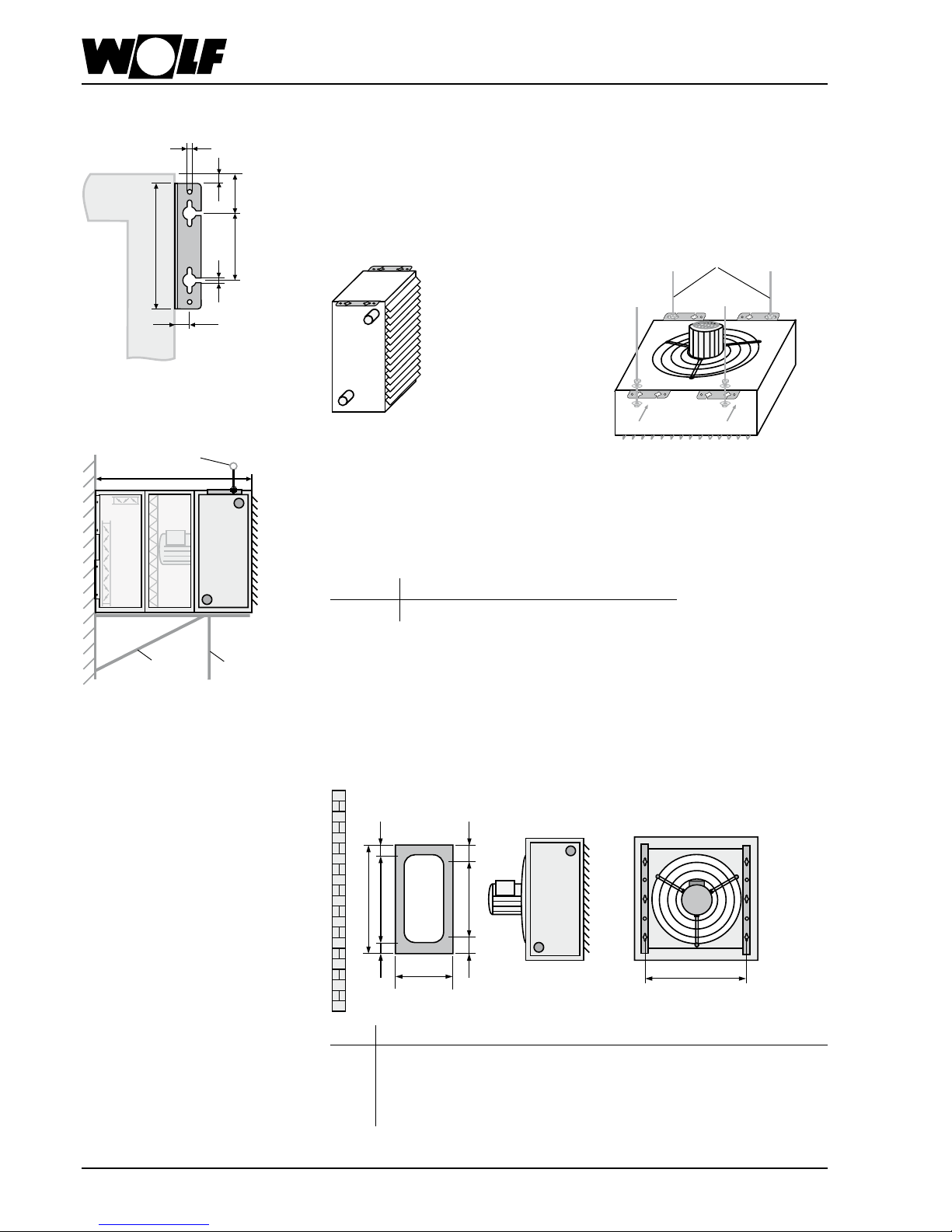
Installation Instructions
Suspension angles
Attach the suspension angles to LH-unit.
For mounting on the ceiling with horizontal air outlet, rst x screws Ø 8 mm (on site)
to the ceiling. Hang up LH-unit at key holes and tighten screws.
For sloping the LH-unit from the ceiling, insert threaded shaft (8 mm) from side through
slot of key holes and tighten by nut, counter-nut and 2 washers.
Depending on the construction of the ceiling, use appropriate screws and dowel pins,
if necessary.
Fix screws Ø 8 mm to wall.
Hang up LH-unit and suction accessory by means of key-holes and tighten screws.
For wall- mounted units exceeding a max. length Lmax. provide an additional support
or suspension on-site.
LH 100 with steel-galvanized heat exchangers type 2 and 3 require this additional
support or suspension already at a unit-length of L = Lmax.
LH 25 40 63 100
L
max.
[mm] 1100 1100 1100 1220
120
65
5
240
25
9
9
Threaded sheft
L
max
Suspension
Bracket
Support
Mounting brackets
Fit mounting brackets to LH-unit by means of enclosed screws.
Attach screws to wall of ceiling according to measure "c".
Hang up LH-unit by means of key holes of mounting brackets and tighten screws.
LH a b c d e f g h i
25 480 250 380 70 30 170 155 155 434
40 480 250 2 x 170 90 50 2 x 170 70 70 564
63 784 350 170+340+170 72 32 3 x 170 137 137 734
100 784 350 170+340+170 72 32 3 x 170 137 137 894
Dimensions en [mm]
a
c
l
b
f
d
g
h
e
x
x
x
x
x
x
Page 9
3040531_0711 9
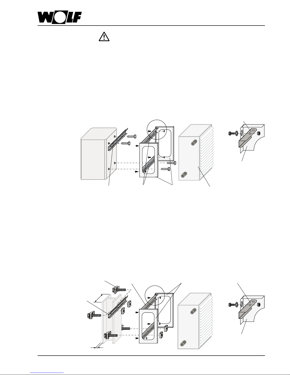
Installation Instructions
Prior to the application of fastening sets the static conditions of the concrete or
steel bars have to be checked and taken into account.
Assembly exclusively with basic units at a total depth of 300 mm.
Fixing
rail
Suspending
rail
Fastening
brackets
LH-Unit
Suspending rail
Fastening bracket
- Fasten xing rail with dowels and screws, provided on site, to the concrete bar.
- Fit fastening brackets to the unit with enclosed screws.
- Fit suspending rails to the fastening brackets with enclosed screws, washers and nuts.
- Hang total assembly (unit fastening brackets and suspending rails) into xing rail.
To prevent the unit from dropping before tting the pipework, the inferior suspending rail
may be secured additionally by tting it to the concrete bar with screws and dowels.
Fastening kit for concrete bar
vertical
Suitable for all types af steel bars at a ange width "b" of min. 100 mm up to max. 300
mm, and a ange thickness "t" of min. 6 mm up to max. 21 mm.
- Fit xing rail to steel bar with enclosed clamping jaws.
- Fit fastening brackets to the unit with enclosed screws.
- Fit suspending rails to the fastening brackets with enclosed screws, washers and nuts.
- Hang total assembly (unit, fastening brackets and suspending rails) into xing rail.
- Fit inferior suspending rail to steel bar with clamping jaws.
Fastening kit for steel bar
vertical
b
t
Fastening bracket
Fixing rail
Clamping jaws
Suspending rail
Fastening bracket
Suspending rail
Page 10

3040531_071110
Fastening kit for steel bar
inclined with inclination
equalization
Suitable for all types of steel bars at a ange width "b" of min. 100 mm up to max. 300
mm and a ange thickness "t" of min. 6 mm up to max. 21 mm.
- Fit fastening brackets to the unit with enclosed screws.
- Fit angle steel proles of inclination equalization with their short end to the suspending
rails, by using the enclosed screws and nuts.
- Connect angle steel proles at their long ends and keep them movable.
- Fit suspending rails to the steel bar with enclosed clamping jaws.
- Fit unit to inclination equalization assembly via its fastening brackets by means of
threaded rods M8 (on site).
b
t
Suspending rail
Fastening
brackets
LH-Unit
Inclination
equalization
Clamping
jaws
Threaded rods
M8 (on site)
b
b
t
t
b
t
Fig. 1 Fig. 2 Fig. 3
*
Fastening kit for steel bar
horizontal and inclined without inclination equalization
Suitable for all types of steel bars at a ange width "b" of min. 100 mm up to max. 300
mm and a ange thickness "t" of min. 6 mm up to max. 21 mm.
- Fit fastening brackets to the unit with enclosed screws.
- Fig. 1 and 2: - Fit suspending rails to the fastening brackets with enclosed
screws, washers and nuts.
- Fit suspending rails to the steel bar with enclosed clamping
jaws, as shown in g. 1 and 2.
- Fig. 3: - Fit suspending rails to the steel bar with enclosed clamping
jaws.
- Fit unit to suspending rails via its fastening brackets by means
of threaded rods M8 * (on site).
Installation Instructions
Page 11

3040531_0711 11
Operation of several LH-units with
one switch or control device
LH-units of different sizes and capacity
can be oberated with one switch up to the
max. permissible capacity or max. permissible current of the switch.
When operating several LH-units, the motor terminals have to be switched parallel,
the thermal cutouts and anti-frost thermostats in line! Terminal clamp 5 on site.
U1 V1W1W2 U2 V2 PE 12 11
U1 V1W1W2 U2 V2
TK TK R1 R25PE
U1 V1
W1
W2U2V2 PE 12 11
5
U1 V1W1W2 U2 V2 PE 12 11
5
LH-unit with thermal cutouts
LH-step-switch or conrol device
(i.e. step-switch DS)
U1 V1W1W2 U2 V2 PE 12 11
124PE
U1 V1W1W2 U2 V2
TK TK R1 R25PE
U1 V1W1W2 U2 V2 PE 12 11
124PE
5
U1 V1W1W2 U2 V2 PE 12 11
124PE
5
LH-step-switch or control device
(i.e. step-switch DS)
LH-unit with termal cutouts
and anti-frost thermostat
L1
11 N12
PE
11
Z1
U1 Z212U2
PE
PE NL1R1 R2 NVMPE
5-step-switch E5-3
Terminal box at mixing box
11
Z1
U1 Z212U2
PE
PE NL1R1 R2 NVMPE
5-step-switch E5-3
Single-phase-AC-motors
230 V / 50 Hz
Single-phase-AC-motors are delivered
only in high-speed-wiring.
Wire thermal cutouts in line with motor
winding.
Speed control with 5-step-switch
type E5-...
Three-phase-motors
High speed
TKL3 TKL1
11W2
U1
PE
V1
12W1
V2
U2
PEL2
Low speed
TKL3 TKL1
11W2
U1
PE
V1
12W1
V2
U2
PEL2
Electrical Connection
Page 12

3040531_071112
Switches
Without switches for complete protection we do not give motor warranty!
When the winding temperature is being exceeded without a complete motor protection switch, the motor can get badly
damaged.
Complete motor protection switches for 3 x 230 V available on request.
Attention :
1) TK / 11-12
* When connecting a room thermostat remove link
K!: 3/4 contact for heating requirements
Two-step switch DS
for two-speed operation of one or several
unit heaters.
Automatic start-up when winding temperature drops (motor).
Operation voltage 400 V
Control voltage 230 V
Max. capacity 4 kW
Weight 0,9 kg
Prot. class IP 54
Part no. 79 25 110
PE
N
L3
L2
L1
U1
2
1
U1
V1
W1
W2
U2
V2
11
PE
12
V1 W1 4
R2
N
K1
L1 L2 L3 3
S1
F1
3,15A
J
Single-step switch D1
for single-speed operation of one or several
unit heaters.
Automatic start-up when winding temperature drops (motor).
Operation voltage 400 V
Control voltage 230 V
Max. capacity 3 kW
Weight 0,9 kg
Prot. class IP 54
Part no. 79 40 001
1) TK / 11-12
* Link acc. to motor type-plate
** Link is not applicable with room thermostat
K!: 3/4 contact for heating requirements
Room
thermostat
L1
L2
L3
N
U1
V1W14
1
24 610812 13
5714
L1 L2 L3 3
210
R2
N
K1
S1
F1
3,15A
U1 V2V1 W1 TK TK R1 5R2 PEW2 U2
U1
V1
W1
W2
U2
V2
11
PE
12
Page 13

3040531_0711 13
Without switches for complete protection we do not give motor warranty!
When the winding temperature is being exceeded without a complete motor protection switch, the motor can get badly
damaged.
Complete motor protection switches for 3 x 230 V available on request.
Attention :
Switches
Fan motor with
thermal cutout
Link acc.
to motor
type-plate
* When connecting a room thermostat remove link
H1 = Sevice
H2 = Interruption
Five-step switch D 5-...
for ve-speed operation of one or several
unit heaters with complete motor protection
with reclosure preventing device.
Locking switch-off at winding overtemperature (motor).
Reclosing: switch position 0, then select requiered stage.
Contact for heating requirements.
* Whenn connecting a room thermostat remove link
Fan motor with
thermal cutout
Five-step switch E 5-3
for ve-speed operation of one or several
unit heaters with single-phase-AC-motors
with complete motor protection.
Automatic start-up when winding temperature drops (motor).
Operation voltage 230 V
Max. current 3 A
Weight 4,0 kg
Prot. class IP 40
Part no. 27 40 006
Type D5-1 D5-3 D5-7 D5-12 D5-19
Operation
voltage
V 400 400 400 400 400
Control voltage V 230 230 230 230 230
Max. current
A 1 2 4 7 12
Weight kg 4,5 7,0 9,0 19,0 27,0
Prot. class IP 40 20 20 20 20
Width A 150 230 230 230 310
Height B 200 310 310 310 385
Length C 175 185 185 185 225
Part number 2740015 2740010 2740013 2740014 2740017
Page 14

3040531_071114
Switches
3-stage switch D 3-4
with reclosing lock-out
for 3-speed operation of one or more unit
heaters with complete motor protection
Locking switch-off at winding overtemperature (motor).
Reclosing: switch position 0, then select
required stage.
Contact for heating requirements.
Operation voltage 400 V
Control voltage 230 V
Max. capacity 4 A
Weight 8,0 kg
Prot. class IP 20
Part no. 27 01 065
* When connecting a room thermostat remove link
H1 = Service H2 = Interruption
S1/K1 = Contact seizure depending on manufacture type
Contact 3-4 heating requirements
F2, F3, F4 = 5 AT
Link acc. to
motor typeplate
Fan motor with thermal
cutout
* When connecting a room thermostat remove link
H1 = Service H2 = Interruption
S1/K1 = Contact seizure depending on manufacture type
Contact 3-4 heating requirements
Fan motor with
thermal cutout
3-stage switch E3-7T
with reclosing lock-out
for 3-speed operation of one or more unit
heaters with single-phase A.C. motors and
complete motor protection.
Locking switch-off at winding overtemperature (motor).
Reclosing: switch position 0, then select
required stage.
Contact for heating requirements.
Operation voltage 230 V
Max. capacity 7 A
Weight 4,5 kg
Prot. class IP 40
Part no. 27 01 064
supply cable
Page 15

3040531_0711 15
Control Devices for Damper Actuators
Automatic relay A1
Auxiliary relay for the automatic operation of
the fresh air damper with an actuartor 230 V
"OPEN-SHUT".
The automatic relay A1 switches the actuator
to position "SHUT", if the LH-unit is switched
off or if the anti-frost thermostat is activated.
Switching on the LH-unit, the actuator
switches to position "OPEN".
Control voltage 230 V
Max. capacity 3 kW
Weight 0,5 kg
Prot. class IP 54
Part no. 79 65 020
Actuator
Open/Shut
Reverse
function by
changing of
2 and 3
Automatic
relay A1
Anti-frost
thermostat
Selection
switch fresh
air/mixed air
(on site)
Actuator
Open-Shut
Switch
Automatic
relay A1
Reverse function
by changing of 2
and 3
Automatic relay A1S
Auxiliary relay with integrated position
transmitter for the automatic operation of the
mixed air damper by means of a stepless
actuator 230 V.
The automatic relay A1S switches the
actuator to the position set on the position
transmitter, if the LH-unit is switched off or if
the anti-frost thermostat is activated.
Switching on the LH-unit, the actuator
switches to the position set at the position
transmitter.
Control voltage 230 V
Max. capacity 3 kW
Weight 0,5 kg
Prot. class IP 54
Part no. 79 65 012
K
K
A1
L1
L2
L3
N
PE
10
F1
T 3,15 A
A2
2
12
PE
L1
N
1
2
3
3
111
3489
A1S
M
1~
Actuator
stepless
Position
transmitter
Control device
Page 16

3040531_071116
Thermostats
Max. current at 230 V / 50 Hz
Heating: 10(5) A; Venting: 5(2) A
Thermal feed-back
Temperature range 5 - 30 °C
Differential ± 0,5 K
Protection class IP 30
Part no. 27 34 000
Room thermostat
Max. current at 230 V / 50 Hz
Heating: 10(4) A; Venting: 5(2) A
Thermal feed-back
Temperature range 5 - 30 °C
Differential ± 0,5 K
Protection class IP 30
Part no. 27 34 700
Room thermostat
mith summer-winter-switch
Step switch
Room thermostat
Max. current at 230 V / 50 Hz
Heating: 16(4) A; Venting: 8(4) A
Temperature range 0 - 40 °C
Differential ± 0,75 K
Protection class IP 54
Part no. 27 35 300
Room thermostat
Heavy-duty-design
3
J
1
2
Max. current 10(4) A at 230 V / 50 Hz
Temperature range 5 - 40°C
Differential adjustable 2 - 10 K
Differential ± 0,1up to 3 K
Storage locations 16
Function reserve 15 minutes
Shortest switching interval 10 minutes
Protection class IP 20
Part no. 27 44 079
Room thermostat clock
with weekly program
external
remote sensor
(optional)
Plastic housing 52 x 50 x 35 mm
Screw connection M16
Protection class IP 54
Part no. 27 35 410
Remote sensor for room
thermostat clock
Anti-frost thermostat
24
J
1
Max. current 10 A at 230 V / 50 Hz
Range 4,5 °C bis 22 °C
Differential 2,5 K
Prot. class IP 43
Wiring of anti-frost thermostat in line with
thermal cutouts!
LH 25 40 63 100
Part no. 27 30 050 27 30 150
Page 17

3040531_0711 17
• room-dependent temperature control
• control by rotary selector with key function
• 4 function keys for frequently used functions (info, temperture,
speed adjustment, fresh air proportion)
• installation either inside the ventilation control unit or, as remote
control, in a wall mounting base
• only one BML ventilation programming module required to control
up to 7 zones
• demand-optimised boiler water temperature demand via eBUS
• eBus interface
BML ventilation programming
module
• wall mounting base for use with the BML ventilation programming module as
remote control.
Wall mounting base
• ventilation module to control air heaters with a two-stage motor
• easy controller conguration by selecting one of the preset system versions
• demand-optimised room temperature control via air heater speed
• control of the heating circuit pump
• control of one heat source
• demand-optimised boiler water temperature demand via eBUS
• eBus interface with automatic energy management
LM1 Ventilation control unit
(incl. room temperature sensor)
LM2 ventilation control unit
• ventilation module LM2 to control the room temperature via speed or mixing valve
• 2-stage motor control in conjunction with ventilation module LM1, or variable
motor control in conjunction with EC motor or external inverter (0-10 V)
• easy controller conguration by selecting one of the preset system versions
• control of one heat source
• demand-optimised boiler water temperature demand via eBus
• eBus interface with automatic energy management
• control of mixed air damper
• induction louvre control
Outside or room temperature sensor
Radio clock
• for synchronising the clock inside the control unit with the DC77 transmitter
Radio clock with outside temperature sensor
• for synchronising the clock inside the control unit with the DC77 transmitter, and
capturing the outside temperature
Supply air sensor and sensor retainer
Control System WRS
Page 18

3040531_071118
2
1
4
5
3
6
BML
Netz
LM1/X1
X1/B2
X1/M2
B1
X1/M1
X1/B3
X1/K1
X1/eBus
supply
Control System WRS
Ventilation control unit LM1
with BML
Installation diagram:
No. Description
1 room sensor
2 outside sensor
3 external release
4 2-stage motor
5 heating circuit pump
6 heat source
Description:
Example:
Unit heater, heating with room
temperature control
supply
unit heater
boiler
heating
circuit pump
room
sensor
BML
OS
LM1
This conguration is used for heating buildings in conjunction with air heaters. The
room temperature is captured by a sensor and the fan, the heating circuit pump and
the heat source are switched on or off depending on demand.
If the temperature deviation (set room temperature to actual room temperature) is low,
the fan is operated in stage 1. If the temperature deviation is greater, it is switched to
stage 2.
Page 19

3040531_0711 19
unit heater
Heizkessel
supply
LD15
supply
mixed air
HCP
mixing
valve
induction
louvre
anti-frostthermostat
room
sensor
ceiling
sensor
supply air
sensor
BML
AF
LM1 LM2
Control System WRS
Ventilation control units LM1
and LM2 with BML
This conguration is used for heating buildings in conjunction with air heaters. The
room temperature is captured by a sensor and the fans, the heating circuit pump, the
heating circuit mixing valve and the heat source are switched on or off depending on
demand.
Description:
12
9
5
13
7
2
3
14
4
1
1011
8
Netz
SS
Netz
LM1/X1
LM2/X2
BML
X2/M1
X2/B3
X1/Y2
M1
X1/K1
eBus
X1/M2
X1/Y1
X2/M2
B1
X1/B5
X1/B1
X1/Y3
X1/B2
X1/B4
LM2/X1LM1/X2
Example:
Unit heater, heating with room temperature control,
mixing valve control, motor control,
2-stage
No. Description
1 room sensor
2 supply air sensor
3 outside sensor
4 ceiling sensor
5 external release
7 anti-frost thermostat
8 induction louvre
9 2-stage motor
10 heating circuit pump
11 heating circuit mixing valve
12 heat source
13 mixed air damper
14 LD15, ceiling fan
supply
boiler
Installation diagram:
supply
Page 20

3040531_071120
Control System WRS
LM2 Ventilation control unit with
BML
This conguration is used for heating buildings in conjunction with air heaters. The
room temperature is captured by a sensor, and the fans, the heating circuit pump, the
heating circuit mixing valve and the heat source are switched on or off depending on
demand. The extract air fan is activated depending on the fresh air proportion.
Description:
Example:
Unit heater, heating with room temperature control,
mixing control, motor control with electronic 5-stage speed regulator
No. Description
1 room sensor
2 supply air sensor
3 outside sensor
4 ceiling sensor
5 mixed air damper
6 fan
7 frequency inverter
8 heating circuit pump
9 heating circuit mixing valve
10 heat source
11 anti-frost thermostat
12 induction louvre
LM2
boiler
Installation diagram:
mixed air unit
mixed air
HCP
mixing
valve
induction
louvre
anti-frost
thermostat
room
sensor
ceiling
sensor
supply
air
sensor
electronic 5-stage
regulator
BML
OS
supply
extract air
unit
electronic 5-stage
regulator
supply
supply
supply
supply
supply
supply
Page 21

3040531_0711 21
Actuators / Push-button
Push-button for 230V/50Hz
actuator of induction louvre
for surface or concealed installation;
for progressive control of the induction louvre to optimize the air throw
124
5
1
1
N
L
N
PE
LM
2
Zu
230
3
Auf
W
2
Zu Auf
actuator
open-closed
230V
induction
louvre
surface/concealedtype push-button
auxiliary
terminal on site
83
113
53
Control voltage 230 V
Max. capacity 10 A
Prot. class IP 20
Part no. 27 01 063
Actuator for automatic operation of damper,
induction louvre and mixing valve.
Controlling only by automatic relay A1 and
position transmitter.
Power consumption 5 VA
Rotation direction reversible
Torque drive 15 Nm
Running time 100 - 200 sec.
Protection class IP 42
Part no. 22 69 522
Stepless actuator 230 V / 50 Hz
Actuator for automatic opening and closing of the fresh air damper.
Controlling only by automatic relay A1.
Power consumption 11 VA
Rotation direction reversible
Torque drive 15 Nm
Running time 90 - 150 sec.
Protection class IP 42
Part no. 22 69 523
N
2
3
4
3
1
PE
ZU
N
AUF
SM 220
PE
Relay A1
Actuator OPEN-SHUT 230 V / 50 Hz
shut open
Page 22

3040531_071122
Intermediate Terminal Box
Operation of 7 LH-units with intermediate terminal box
intermediate terminal box
intermediate terminal box
switch or
control device
intermediate terminal box
Intermediate terminal box
Connection of 3 LH unit heaters with an intermediate terminal box
intermediate terminal box
switch or control
device
Intermediate terminal box for a parallel operation of several LH unit heaters.
It is possible to wire one control device and three LH unit heaters or one control device,
two LH unit heaters and an additional intermediate terminal box.
LH unit heaters of different sizes and performances of up to the max. possible performance or rather the max. possible current of the switch or control device can be wired.
Wiring according to the attached wiring diagrams.
Page 23

3040531_0711 23
Frost protection measures
When unit is switched off: Drain all water-lled sections, blow out remaining water with
compressed air!
Steam heating coils being directly operated with fresh air have to be provided with
steam on total height.
Maintenance
Attention: Do not clean electric heaters with water!
For cleaning the heat exchanger from dust and dirt use vacuum cleaner or compressed
air. For higher dirt accumulation use additionally commercial washing agents and luke
warm water or compressed steam (not over 5 bar).
Pull out the lter element on the access side to clean or to renew it.
The lter element can be cleaned with the help of compressed air, batting or vacuum
cleaner.
All the remaining parts as motor, fan-impeller, mixing-box, adjustable ns and actuator
are maintenance-free.
Prior to nishing maintenance, check safe fastening of the LH-unit.
Before operation and after a longer rest period the pump has to be vented. For this
purpose, the LH-unit has to be switched off. To proceed accordingly, remove plug acc.
to sketch. When water is evacuated the plug is closed tightly again.
The direction of rotation of the pump is marked with arrows on the type-plate.
Pumps operating with AC always turn into the correct direction of rotation.
Pumps operating with three-phase current have to be checked by removing the plug
(threaded to the right) and by controlling the rotation of the shaft.
Pump
Maintenance / Frost Protection Measures
Page 24

3040531_071124
Hydraulic Adjustment of Unit Heaters
operating as a group
The hydraulic adjustment of unit heaters is a precondition for an economic and optimized
control within a group. The hydraulic adjustment aims at a correct ow rate through all
unit heaters.
General instructions
Example 2:
Pipework assembly according to the Tichelmann system
(equally long pipes per unit heater replace the individual adjustment)
VL
RL
advantage: no pressure adjustment required
disadvantage: higher expenditure of pipework
unit heater
boiler
Individual adjustment via control valves ( in addition to the connection ttings).
Example 1:
VL
RL
advantage: low expenditure of pipework
disadvantage: pressure adjustment required for
each unit heater
unit heater
control valve
boiler
Page 25

3040531_0711 25
Rain protection hood and roof lead-in box
Roof lead-in box and rain protection hood are supplied sepa
rately. The rain protection hood is provided with a bird screen as standard. As an option
a non-return damper may be supplied for the installation into the rain protection hood,
on site.
In order to facilitate the sealing of the roof on site, it is possible to supply a covering
collar as an optional accessory, not tted.
Installation and tting in accordance with the drawing:
Roof sealing
X
Fit sealing material
on site (included)
Covering collar
Installation and
sealing on site
X
Rain protection
hood
Roof sealing
(on site)
Covering collar
Installation and
sealing on site
Roof lead-in box
As an option and on extra price it is possible to supply 4 fastening angles for tting
the roof lead-in box. Fitting of fastening angles to be done on site because of different
types of roofs and variable pitch.
Roof fastening
Notice:
The fastening angles are exclusively suitable for tting the roof lead-in box. They are
not designed for carrying the additional weight of unit components installed underneath
the roof lead-in box.
External tting of
fastening angles
as well possible
4 x fastening angles to
be adapted to the pitch
of the roof
Roof lead-in box
Roof
Page 26

3040531_071126
Rain protection hood and roof lead-in box
Flexible connection
4 x angle brackets of unit
heater, only tted when
ordered
A unit heater or mixing box are connected to the internal ange of the roof lead-in box
(matching bore holes) via a exible connection "Q". In this case the roof lead-in box has
to be on the roof and the mixing box, lter section or unit heater underneath the roof.
Flexible connection
Roof lead-in box
Flange of angle prole
on the whole perimeter;
generally spot-welded
Unit heater
Direct tting of unit heater or mixing box to the external angle ange.
This ange is provided with the matching bore holes for the angle brackets of the unit
heater, mixing box or lter section on the whole perimeter.
Non-exible connection
Roof lead-in box
Flange of angle prole
on the whole perimeter;
generally spot-welded
4 x angle brackets of
unit heater, only tted
when ordered
Unit heater
Page 27

3040531_0711 27
Notes
Page 28

Wolf GmbH · Postfach 1380 · 84048 Mainburg · Tél. 08751/74-0 · Fax 08751/741600 · Internet : www.wolf-heiztechnik.de
 Loading...