

Page 1
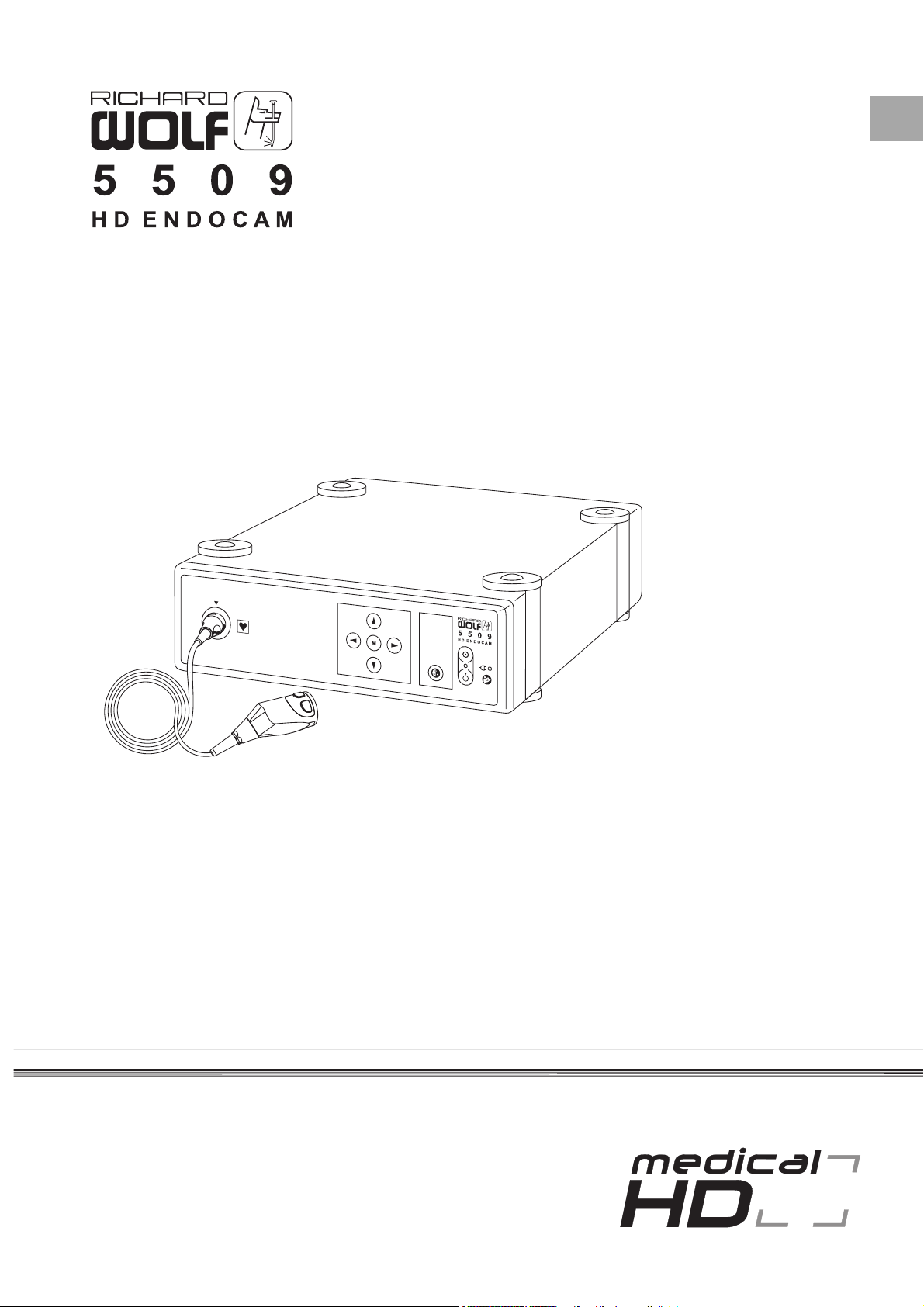
Manual
EN
DE
Page 2

This manual contains information that is subject to copyright. All
EN
registered trademarks but are not identified as such. It should therefore not be
assumed that the absence of the trademark indicates that any given designation is not subject to trademark protection.
Users of RICHARD WOLF GmbH-products should not hesitate to point out to us
any errors or unclarities in this manual.
Copyright © RICHARD WOLF GmbH
rights reserved. This manual should not be photocopied, duplicated on microfilm or otherwise copied or distributed, completely or
in part, without the approval of RICHARD WOLF GmbH.
Some of the parts and equipment referred to in this manual bear
Manufacturer
RICHARD WOLF GmbH
Pforzheimer Straße 32
75438 Knittlingen, Germany
www.richard-wolf.com
CE marking according to Directive 93/42/EEC
GA-A 250 / Index: 03-10-3.0
Model
HDC905/10000005566 02/0310/ama
Page 3
EN
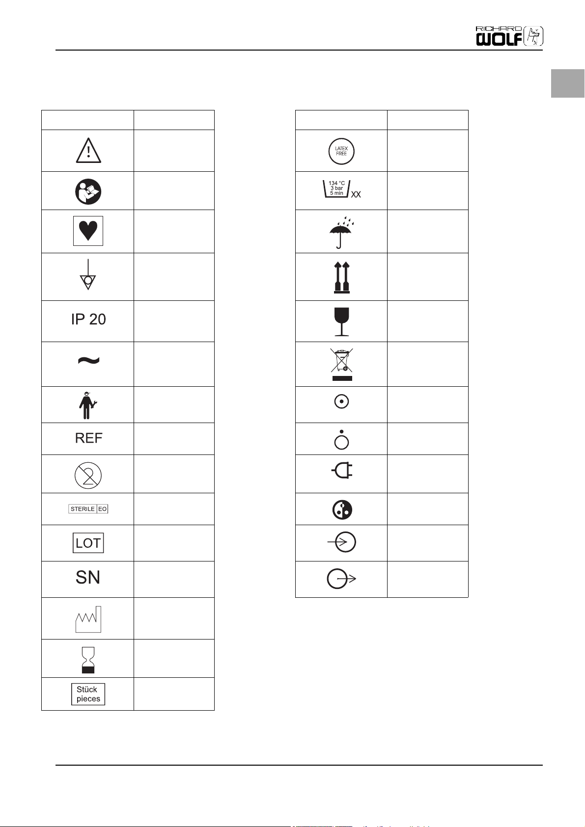
Symbols
Warning Latex free
Follow the instruction
for use
Symbol for type CF
equipment
Symbol for potential
equalization
Degrees of protection
provided by enclosures
(IP-Code)
Alternating current Waste management
Service
Symbols
Number of autoclaving
cycles
Do not get wet
Top-Bottom
Fragile
ON
(part of equipment)
Order number
Single use only
Sterile with ETO White balance
Lot no.
Serial number Output
Date of manufacture
Expiration day
Pieces, quantity
OFF
(part of equipment)
Power connected
Input
Page 4

Page 5

Table of Contents
1 Important User Notes ......................................................................................................................................................... 3
2 Safety Information.............................................................................................................................................................. 4
2.1 Hazards........................................................................................................................................................................................ 4
3 Device Purpose.................................................................................................................................................................... 8
3.1 Intended Use.............................................................................................................................................................................. 8
3.2 Device-inherent Dangers and Information....................................................................................................................... 8
4 Initial Device Startup .......................................................................................................................................................... 10
4.1 Scope of Delivery...................................................................................................................................................................... 10
4.2 Preparing the Device ............................................................................................................................................................... 10
4.2.1 Connecting the Camera Heads to the C-Mount Lens System ..................................................................................... 11
4.3 Camera Control Unit (CCU), Front........................................................................................................................................ 11
4.4 Camera Control Unit (CCU), Rear......................................................................................................................................... 12
4.5 Camera Head (User Part)........................................................................................................................................................ 14
4.6 Connecting the Equipment ................................................................................................................................................... 14
4.6.1 Connecting Camera Head with Camera Control Unit (CCU)........................................................................................ 14
4.6.2 Connecting Monitor and Endoscope.................................................................................................................................. 15
4.6.3 Connecting Potential Equalization...................................................................................................................................... 17
4.6.4 Connecting the Mains Connection Cable.......................................................................................................................... 17
4.6.5 Connecting an Endoscope to the Camera Head.............................................................................................................. 18
4.6.6 Performing White Balance .................................................................................................................................................... 18
4.6.7 Assigning Functions to Head Keys ...................................................................................................................................... 19
5 Operating the Device .......................................................................................................................................................... 20
5.1 Using the Quick Coupling...................................................................................................................................................... 20
5.2 Using a Sterile Cover/Sleeve ................................................................................................................................................. 21
5.3 Using Camera Head without C-Mount Lens System, e.g. on Microscope................................................................ 22
5.4 Camera Menus.......................................................................................................................................................................... 22
5.4.1 Start Menu ................................................................................................................................................................................. 22
5.4.2 User Menu.................................................................................................................................................................................. 22
5.4.3 Procedure Profiles .................................................................................................................................................................... 26
5.4.4 User Profiles............................................................................................................................................................................... 27
5.4.5 Assigning Functions to Head Keys ...................................................................................................................................... 27
5.4.6 Image Functions ....................................................................................................................................................................... 28
5.4.7 Additional Settings .................................................................................................................................................................. 29
5.4.8 Language .................................................................................................................................................................................... 29
5.5 Using the Head Key Functions.............................................................................................................................................. 30
6 Care and Maintenance........................................................................................................................................................ 33
6.1 User Part ..................................................................................................................................................................................... 33
6.1.1 Cleaning the User Part............................................................................................................................................................ 33
6.1.2 Disinfecting the User Part...................................................................................................................................................... 34
6.1.3 Sterilization of the User Part................................................................................................................................................. 35
6.2 Cleaning the Camera Control Unit (CCU) .......................................................................................................................... 36
7 Troubleshooting.................................................................................................................................................................. 37
8 Technical Data..................................................................................................................................................................... 38
9 Guidelines and Manufacturer's Statement - Electromagnetic Compatibility ................................................................... 41
9.1 Impact of Mobile and Portable HF Communication Devices....................................................................................... 41
9.2 Guidelines and Manufacturer’s Statement – Electromagnetic Emissions .............................................................. 41
9.3 Guidelines and Manufacturer's Statement - Electromagnetic Interference Immunity....................................... 42
9.4 Guidelines and Manufacturer's Statement - Electromagnetic Interference Immunity - for the Camera ...... 43
9.5 Recommended Safety Distances between Portable and Mobile HF Telecommunications Devices and the
Camera ........................................................................................................................................................................................ 44
10 Accessory List ...................................................................................................................................................................... 45
11 Glossary............................................................................................................................................................................... 47
12 Appendix............................................................................................................................................................................. 48
12.1 Return Form............................................................................................................................................................................... 48
Index.................................................................................................................................................................................... 49
EN
Page 6

Page 7

1 Important User Notes
Read the manual carefully and become familiar with the operation and function
of the device and the accessories before use during surgical procedures. Non-observance of the instructions listed in this manual can lead
• to life-threatening injuries of the patient,
• to severe injuries of the surgical team, nursing staff or service personnel, or
• to damage or malfunction of device and/or accessories.
technical data of the supplied product through continued product development.
marked with these words must be read especially attentively.
DANGER!
The safety and/or health of the patient, user, or a third party are at risk. Comply
with this warning to avoid injury to the patient, user, or third parties.
WARNING!
These paragraphs include information provided to the operator concerning the
intended and proper use of the device or accessories.
Important User Notes
EN
Subject to technical changesThe manufacturer reserves the right to modify the appearance, graphics, and
Please noteThe words DANGER, WARNING, and NOTE carry special meanings. Sections
NOTE!
Here you will read information about the maintenance of the device or the ac-
cessories.
3
Page 8

EN
Safety Information
2 Safety Information
Federal Law (only for U.S. market) U.S. federal law restricts use of this device to u se by or on the ord er of a physi cian .
Exclusion of liability The manufacturer is not liable for direct or consequential damage and the war-
ranty is null and void if:
• the device and/or the accessories are improperly used, prepared, or maintained,
• the instructions and rules in the manual are not adhered to,
• non-authorized persons perform repairs, adjustments, or alterations on or to the device or accessories,
• non-authorized persons open the device,
• the prescribed inspection and maintenance schedules are not adhered to.
Receipt of technical documentation from the manufacturer does not authorize individuals to perform repairs, adjustments, or alterations on or to the device or accessories.
Authorized service technician Only an authorized service technician may perform repairs, adjustments, or al-
terations on the device or accessories and use the service menu. Any violation will
void the manufacturer's warranty. Authorized service technicians are only
trained and certified by the manufacturer.
Intended use The device may be used only as intended.
Care and maintenance The service and maintenance of the device and its accessories has to be carried
out as per instructions to ensure the safe operation of the device. For the protection of the patient and the operating team, check that the device is complete and
functional before each use.
Contamination Before shipping, decontaminate device and accessories in order to protect the
service personnel. Follow the instructions listed in this manual. If this is not possible,
• the product must be clearly marked with a contamination warning and
• is to be double-sealed in safety foil.
The manufacturer has the right to reject contaminated products for repair.
Waste management
This symbol indicates that the waste of electrical and electronic equipment must
not be disposed of as unsorted municipal waste and must be collected separately
instead. Please contact the manufacturer or an accordingly authorized disposal
or waste management company for further information.
2.1 Hazards
DANGER!
Technique and procedures
Only the physician can evaluate the clinical factors involved with each patient
and determine if the use of this device is indicated. The physician must determine the specific technique and procedure that will accomplish the desired clinical effect.
DANGER!
Check all factory settings.
Factory settings are not mandatory settings for the physician. The physician is re-
sponsible for all settings affecting the surgical procedure.
4
Page 9
DANGER!
Original accessories
For your own safety and that of your patient, use only original accessories.
DANGER!
Not explosion-proof
The device is not explosion-proof. Do not use in an area where flammable anes-
thetic gases are present.
DANGER!
Risk of electrical shock
To prevent electrical shock, do not open this device. Never open this device your-
self. Refer servicing to qualified service personnel.
DANGER!
Professional qualification
This manual does not include descriptions or instructions for surgical proce-
dures/techniques. It is also not suitable for training physicians in the use of surgical techniques. Medical peripherals and devices may be used only by
physicians or medical assistants with the appropriate technical/medical qualification working under the direction and supervision of a physician.
Safety Information
EN
DANGER!
Function test
The function test must be performed prior to each surgery.
DANGER!
Sterile mediums and accessories
Always work exclusively with sterile substances and mediums, sterile fluids, and
sterile accessories if so indicated.
DANGER!
Replacement device and accessories
In case the device or any of the accessories fail during surgery, a replacement de-
vice and replacement accessories should be kept within easy reach to be able to
finish the operation with the replacement components.
DANGER!
Cleaning the device
Do not sterilize the device.
DANGER!
Condensation / Water penetration
Protect device from moisture. Do not use if moisture has penetrated the device.
5
Page 10
EN
Safety Information
DANGER!
Replacing fuse
Replace the fuse only with a fuse of the same type and rating.
DANGER!
Device-inherent dangers
Read the warnings specific to this device in chapter 3.2 "Device-inherent Dan-
gers and Information".
DANGER!
Device defect
If a device defect is suspected or confirmed, do not use it. Make sure the device
can no longer be used until a qualified service technician conducts the appropriate tests and repairs.
DANGER!
Powered accessory
The residual current flowing through the patient could increase when using endoscopes with electrically powered accessories.
DANGER!
Obvious defects
Never use the device if it has obvious defects, especially if these involve the power plugs or the mains power supply connection cables. In this case have the de-
vice repaired by authorized service personnel.
WARNING!
Check to make sure the available mains voltage matches the data listed on the
type label attached to the back of the device. Incorrect voltage can cause errors
and malfunctions and may destroy the device.
WARNING!
Endoscope
The device may only be connected with endoscopes designed for and featuring
the technical specification permitting such a combined use. Any utilized endo-
scopes must comply with the most recent versions of EC 60601-2-18 and
ISO 8600.
WARNING!
Electrical Interference
(See chapter 9 "Guidelines and Manufacturer's Statement - Electromagnetic
Compatibility"). Electrical interference with other devices or instruments was
practically eliminated when developing this devices and none was detected during testing. However, if you still detect or suspect such interference, please follow these suggestions:
• Move this, the other or both devices to a different location
• Increase distance between used devices
• Consult an electro-medical expert
6
Page 11

WARNING!
Leakage current
If more power consuming devices are connected simultaneously to one socket by
means of distribution boxes the sum of the individual leakage currents may exceed the tolerated limit values.
Safety Information
EN
7
Page 12
EN
Device Purpose
3 Device Purpose
3.1 Intended Use
The camera is designed to be used in conjunction with endoscopes during minimally invasive surgery. The camera serves to transfer images from an endoscope
to a medical-grade monitor. The camera features a modular design and can be
ordered with different endofocus optical lens systems for different focal lengths.
The camera is designed for positioning on the viewing end of an endoscope but
can also be used in combination with a microscope.
WARNING!
Always use a sterile, disposable cover or sleeve (see chapter 5.2 Using a Sterile
Cover/Sleeve, page 21) when using the endoscopic camera or sterilize the camera as described in chapter 6.1.3 Sterilization of the User Part, page 35). Failure
to do so may lead to contamination of the sterile field and can cause infections.
The camera is an extremely small and light endoscopic device with excellent image quality due to a digital image processing system, perfect color display, and
ease of use. The camera head is connected with the camera control unit (CCU) via
an interchangeable cable. An interchangeable camera cable guarantees the easy
and inexpensive reuse of the whole system in case of a defective cable. Additional
optional modules are used to implement additional functionalities to control
other equipment as well as to control the camera from other devices or with a device control system.
Do not use the device if endoscopic surgery is contraindicated. This device may be used only in rooms equipped and outfitted as specified by VDE Rules 0107.
3.2 Device-inherent Dangers and Information
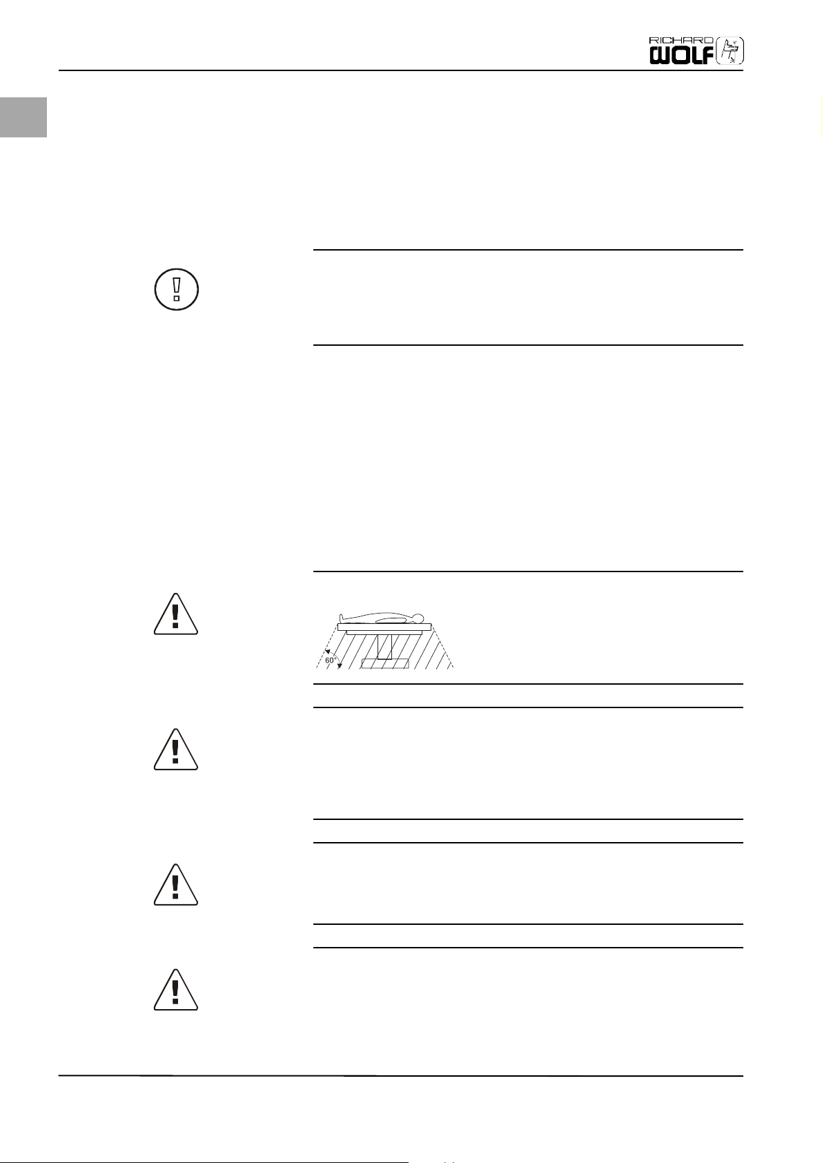
DANGER!
Explosion hazard
The camera is not intended for use in explosive ar-
eas. If explosive narcotic gases are used, the camera
control unit must not be operated in the danger
zone depicted below.
DANGER!
ON/OFF switch
The device is only completely disconnected from the mains power supply if the
power plug is unplugged from the shockproof safety socket. Using the ON/OFF
switch at the front of the device switches only the voltage of the camera head
off.
DANGER!
Installation
The electrical connections of the operating room where the equipment is used
must comply with the corresponding national requirements.
DANGER!
Danger of burns
Contact with the open end of an endoscope or a light cable connected to the light
source can result in burns due to the high energy of the emitted light. Avoid
long-lasting, motionless contact between the end of the endoscope and the patient’s tissue during endoscopic surgery. To avoid danger of burns, do not leave
8
Page 13
an active light-light cable, with or without a connected endoscope, on or near
the patient.
DANGER!
Danger of ignition
Always comply with national regulations concerning avoiding the danger of ig-
nition caused by electrostatic charges.
DANGER!
Device type CF
Degree of protection against electric shock. The endoscope must not have an
electrical conductive connection to the casing of the camera control unit.
WARNING!
Ambient temperature
If the camera control unit is operated within an enclosed device tower or rack
system, the operating temperature within this tower may be higher than the
ambient room temperature. Therefore, always install the equipment in an environment compatible with the manufacturer's rated ambient temperature (see 8
Technical Data, page 38).
Device Purpose
EN
WARNING!
Peripheral devices
Additional peripheral equipment connected to interfaces of the medical monitor
has to meet the requirements of the following specifications: EN 60601-2-18 for
endoscopic devices and EN 60601-1 for electrical medical devices. All configurations have to comply with EN 60601-1-1 specifications. Whoever connects additional equipment to signal output or signal input is obliged to meet
requirements of the standard EN 60601-1-1.
WARNING!
Device interfaces
The device operator may never touch the interfaces of the device and the patient
at the same time.
WARNING!
Mobile telephones
The interference caused by electromagnetic waves (e.g. mobile telephones) affecting electronic devices is well known. These should be avoided.
WARNING!
Endoscopes and accessories
The outer surface of the endoscope and each endoscopically usable piece of additional equipment has to be checked to ensure that the area is free of rough
spots and/or sharp edges that could harm the patient.
9
Page 14
EN
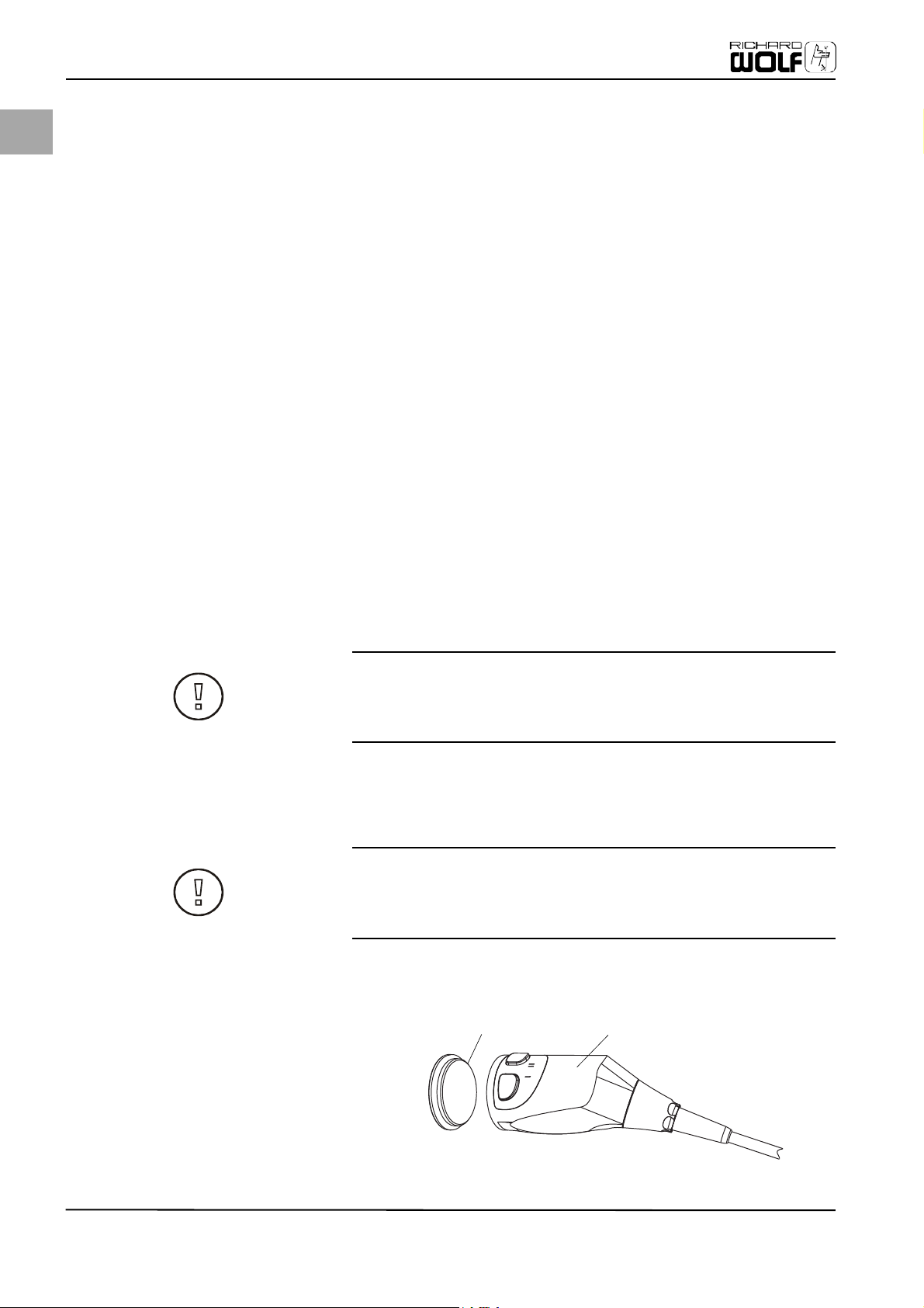
(1)
Initial Device Startup
4 Initial Device Startup
Delivery inspection Always check all parts and accessories of the device immediately after receiving
the shipment. The manufacturer considers only replacement claims that have
been immediately submitted or reported to a sales representative or an authorized service company.
4.1 Scope of Delivery
Check the delivered equipment for completeness. Compare delivered parts with the enclosed packing list.
Returning the device If it becomes necessary to return the device, use of the original packaging is re-
quired. The manufacturer does not take responsibility for damage that has occurred during transportation if the damage was caused by inadequate transport
packaging.
Please make sure that all required information has been supplied:
•Name of owner
•Address of owner
• Device type
• Serial number of the equipment (see identification plate)
• Detailed description of defect
4.2 Preparing the Device
It is the responsibility of the operator to ensure the device is safe and functions as intended when being used.
Setting up the device Place the device on a level surface and install in a dry environment. The ambient
temperature and humidity must meet the requirements mentioned in chapter8
Technical Data, page 38.
WARNING!
Check to make sure the available mains voltage matches the data listed on the
type label attached to the back of the device. Incorrect voltage can cause errors
and malfunctions and may destroy the device.
While using the device the patient must be treated and kept under observation with the usual medical care.
Establish sterile conditions, provided they are required.
WARNING!
Do not use in an area where heating sources or an opening or vent for air condi-
tioning and ventilation are present. Do not expose the unit to direct sunlight, excessive dust, vibrations, or mechanical shocks.
If the camera head is not in use, the protective cap or the lens protector (in case of adapted lens) must be attached.
10
(2)
Page 15
• Remove protective cap (1) from camera head (2).
• The screw lens system onto camera head.
DANGER!
Never pull on the camera cable.
Never squeeze, compress, bend, or otherwise twist or spindle the camera cable.
This can damage the wires inside of the cable and cause image loss or cable failure.
4.2.1 Connecting the Camera Heads to the C-Mount Lens System
WARNING!
Before mounting the lens system, check whether the glass surface of the lens
and the camera head is dry and free of dust. Use a cotton pad (plastic or wood
holders or swabs, never any metal) soaked with alcohol to remove any dirt.
Initial Device Startup
EN
4.3 Camera Control Unit (CCU), Front
(3)
(1)
Please familiarize yourself with the individual elements on the front of the camera control unit (CCU).
(2)
(4)
(5)
(6)
(7)
(8)
(9)
(10)(11)
Fig. 4-1 Elements of the camera control
unit (CCU), front
(1) Camera cable jack
(2) Cursor key LEFT (ESC)
(3) Cursor key DOWN
(4) Menu key (OK)
(5) Cursor key UP
(6) Cursor key RIGHT
(7) White balance key
(8) ON key
(9) Camera head ON/OFF LED
(10) OFF key
(11) Power supply LED
11
Page 16
EN
Initial Device Startup
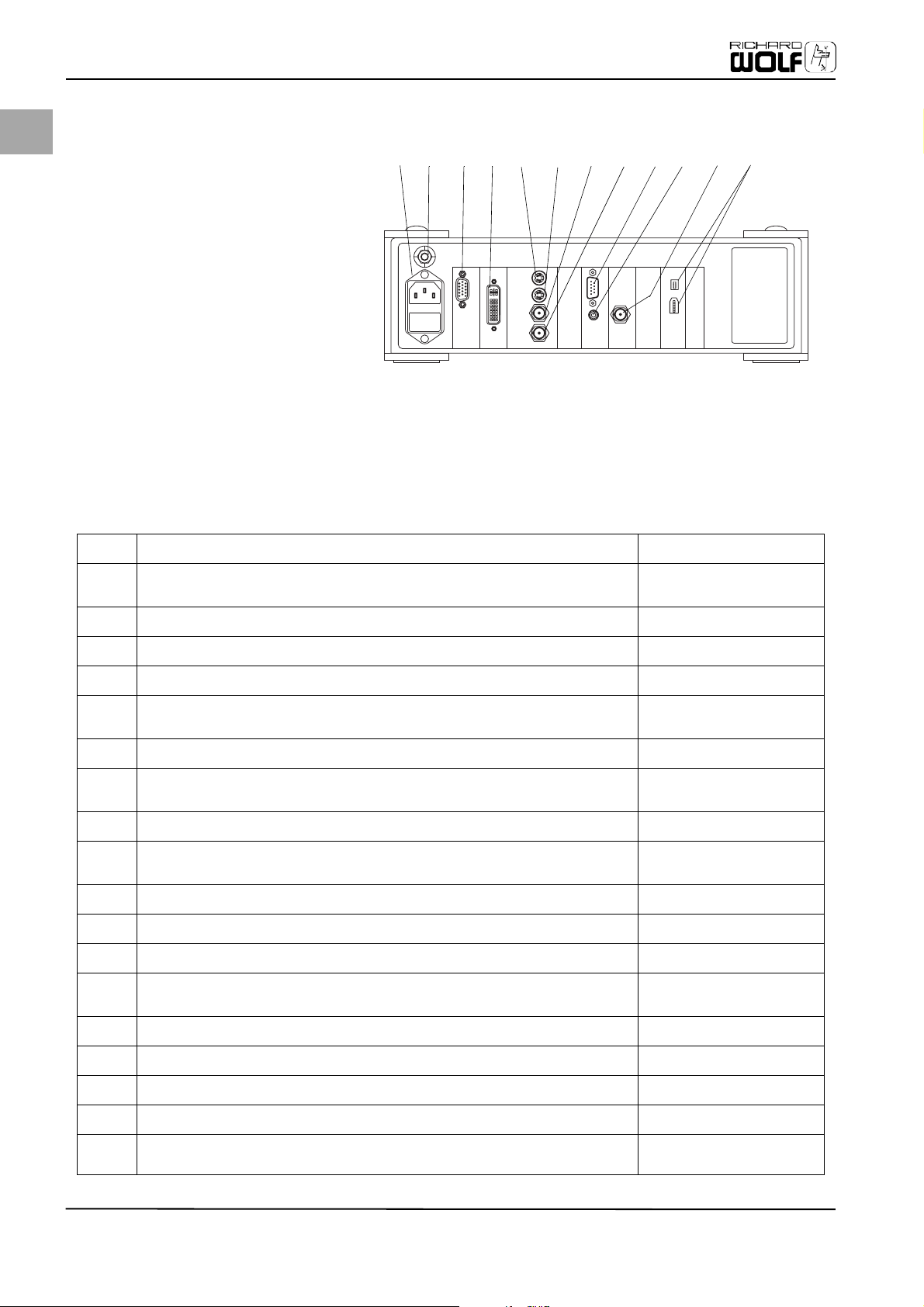
Fig. 4-2 Elements of the camera control
unit (CCU), rear
(12) Mains socket
(13) Potential equalization
(14) HD/RGB output
(15) HD/DVI output
(16A) S-VIDEO output 1
(16B) S-VIDEO output 2
(17A) VIDEO output 1
(17B) VIDEO output 2
(18) Service interface RS232
(19) REMOTE connector
(20) SDI output*
(21) Digital outputs DV
*optional (only Model 5509201)
4.4 Camera Control Unit (CCU), Rear
(12)
(13)
(15)
RGBOUT
(16A)
OUT OUT OUT OUT
(16B)
1
S-VIDEO
21
VIDEO
2
(17A)
(14)
Please familiarize yourself with the individual elements in the rear of the camera control unit (CCU).
(17B)
SC-REMOTE SERVICE
(18)
(19) (20) (21)
SDI
Table 1: Elements of the rear side
(12) Mains power connection Power input
Mains socket: Mains power supply cable connection (comply with rated volt-
Mains socket
age!)
(13) Connection for potential equalization Potential equalization
(14) HD/RGB output: Output of the RGB video signal (15-pin SUB-HD connector plug,
HD/RGB output
resolution 1280x1024)
(15) HD-DVI output (connector socket DVI 24+5) corresponding with ITU-RBT.709
HD/DVI output
digital RGB 24 bit, resolution 1280x1024
(16A) S-Video output 1: Output socket for S-VHS systems (Y/C), separate output for
S-VIDEO output 1
luminance and chrominance
Y: 1 Vpp on 75 ohm
C: 0.3 Vpp burst on 75 ohm
(16B) S-Video output 2: Output socket for S-VHS systems (Y/C), separate output for
S-VIDEO output 2
luminance and chrominance
Y: 1 Vpp on 75 ohm
C: 0.3 Vpp burst on 75 ohm
(17A) VIDEO output 1: BNC output socket for composite video signal, 1 Vpp on 75 ohm VIDEO output 1
12
*optional
Page 17

Initial Device Startup
Table 1: Elements of the rear side
(17B) VIDEO output 2: BNC output socket for composite video signal, 1 Vpp on 75 ohm VIDEO output 2
EN
(18) DATA connector: Serial interface RS 232 C (special cable required): For service
(null modem cable, 9-pin)
(19) REMOTE connector: For remote control functions (relay contacts), e.g. start/stop
of video recorder or video printer.
(20) VIDEO output: BNC output socket for SDI signal.
Digital video signal for the lossless transfer of video up to 300 m.
(21) Firewire/DV output (DV connection 4/6 pin, data rate 400 Mbit/s) Digital outputs
DATA
REMOTE
SDI output*
*optional
13
Page 18

EN
Initial Device Startup
Fig. 4-3 Elements of the camera head
(user part)
(22) Cover lid
(23) Latch
(24) Quick coupling
(25) Focusing ring
(26) Zoom ring
(27) Camera head
(28) CHU plug
(29) Camera cable
(30) CCU plug
(31) Sealing cap for disinfecting
4.5 Camera Head (User Part)
Example with RIWO zoom lens 85261.501
(23)
(24)
(22)
Please familiarize yourself with the location of the individual elements on the camera head.
(25)
(26)
(27)
(28)
(29)
(30)
(31)
4.6 Connecting the Equipment
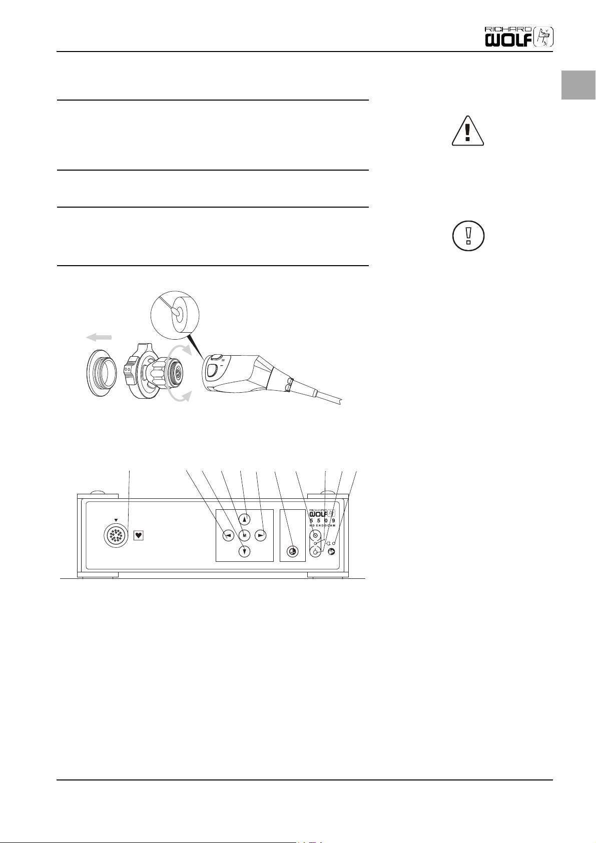
Fig. 4-4 Connecting the camera head
with the camera control unit
(CCU)
(1) Camera control unit (CCU)
(2) Socket for CCU plug
(3) CCU plug
(4) Marking (arrow)
(5) Camera cable
(6) Camera head
(7) Marking
A Detail of socket for the CCU plug
NOTE!
The manufacturer is not liable for direct or consequential damages and the war-
ranty becomes null and void due to improper or incorrect camera assembly.
4.6.1 Connecting Camera Head with Camera Control Unit (CCU)
(1)
(2)
(3)
WARNING!
Ensure the CCU plug (3) is plugged into the socket correctly. Make sure the arrow marking (4) the correct position is where it should be on the camera cable.
(4)
(5)
(6)
(7)
14
WARNING!
The camera control unit CCU may be plugged in or removed only if the camera
control unit (CCU) is switched off (no hot-plugging). If the CCU plug is connected
while the CCU is switched on, the camera control unit (CCU) must be switched off
and on again.
1. Hold the end of the cable with the plug (3) (identified by quarter-turn fasten-
er) so that the recessed grip areas are at the side and the marking arrow (4)
at the camera cable points up.
Page 19

2. Slide plug (3) into socket (2) of the CCU until locked in place. Lock plug by turning clockwise 90°. The recessed grip areas are then on the bottom/top.
without bending or kinking the cable.
4.6.2 Connecting Monitor and Endoscope
Use cable to connect camera and control unit
• with a monitor,
• the camera head, and then connect camera head with an endoscope and an
endoscopic light source,
• and any additional devices if required.
Initial Device Startup
EN
Disconnecting camera cable from CCUUnlock plug by turning counterclockwise 90°. Remove cable by pulling straight
Follow the instructions of the manufacturer of these devices. Choose a suitable
connection for the video signal depending on the required signal quality and the
devices to be connected (see Fig. 4-5 ).
The DVI output should be used to generate the signal with the highest quality. This signal is ideally suited to connect LCD monitors.
Model 5509201 with SDI output must be used for the lossless transfer of video and image information across distances up to 300 meters. This signal is ideally suited to connect LCD monitors.
15
Page 20

Initial Device Startup
EN
Fig. 4-5 Example of how to connect to a
monitor and a video recorder
(1) Camera control unit (CCU) Model
5509101
(2) Video cable (BNC)
(3) Y/C Video cable (S-VHS)
(4) Camera control unit (CCU) Model
5509201
(5) SDI Cable (BNC)
(6) Video recorder
(7) DVI Cable (DVI-D)
(1)
(7)
(2)
(6)
(3)
(4)
(5)
16
Page 21

4.6.3 Connecting Potential Equalization
(1)
DIN 42801. Integrate the device into the potential equalization system as specified by local safety rules and regulations.
4.6.4 Connecting the Mains Connection Cable
WARNING!
Check to make sure the available mains voltage matches the data listed on the
type label attached to the back of the device. Incorrect voltage can cause errors
and malfunctions and may destroy the device.
Initial Device Startup
EN
Fig. 4-6 Layout/connection: Potential
equalization
(1) Potential equalization
Potential equalizationThe device is equipped with a potential equalization connection (1) according to
(1)
(2)
(3)
(4)
in easy reach. The power connection must be equipped with a grounding contact.
Make sure the connection data and technical specifications of the mains power
supply comply with DIN VDE or national requirements. Comply with the information listed on the device type plate on the case (operating voltage, etc.). The
mains connection cable (3) must be plugged into a properly installed, grounded
shockproof safety wall socket (4). Use the enclosed mains connection cable to
establish a connection between a grounded shockproof, safety wall socket and
the rear mains socket (2) of the camera control unit. Once the mains connection
is established, the camera control unit (CCU) is switched on.
DANGER!
ON/OFF switch
The device is only completely disconnected from the mains power supply if the
power plug is unplugged from the shockproof safety socket. Using the ON/OFF
switch at the front of the device switches only the voltage of the camera head
off.
Fig. 4-7 Connecting the mains connec-
tion cable
(1) Camera control unit, rear
(2) Mains socket
(3) Mains connection cable
(4) Grounded shockproof safety wall
socket
Grounding contactThe grounded, shockproof safety wall socket should be near the device and with-
grounded safety wall socket) if the device is not being used for several days or
longer.
Disconnect device from power supplyDisconnect the device from the mains power supply (pull cable out off the
17
Page 22

EN
Initial Device Startup
DANGER!
Always grasp the power plug when disconnecting the device from the power
supply. Never pull on the cable itself.
4.6.5 Connecting an Endoscope to the Camera Head
Fig. 4-8 Connect the endoscope to the
camera head
(1) Endoscope
(2) Optical fiber cable
(3) Quick coupling
(4) Camera head
(1)
To attach an endoscope, the camera head must be equipped with an optical lens system featuring a quick coupling (3). If necessary, screw the quick coupling onto the camera head (see also chapter 5.1 Using the Quick Coupling, page 20).
1. Release the quick coupling (3) by pressing the latch and then insert the endoscope (1) into the opened quick coupling.
2. Release latch of quick coupling. This locks the endoscope.
3. Connect the fiber optic cable (2) to the endoscope.
4. Turn the camera and the connected devices on.
The camera will perform a system check and activates all settings stored in the setup menu. The following information is briefly depicted on screen:
(2)
(3)
(4)
4.6.6 Performing White Balance
A white balance has to be performed at the beginning of each surgical procedure using light source and endoscope. Hold a white area (e.g. a white sheet of paper) (2) in front of the optical system to fill the screen completely with the white area.
Fig. 4-9
(1) Camera head
(2) White surface (e.g. a sheet of
paper)
18
(1)
• Press White Balance key (7) (see Fig. 4-1 Elements of the camera control unit
(CCU), front, page 11).
• White balance is depicted on the bottom area of the connected monitor.
• The message Saved appears if the white balance was completed successfully.
• The display is ended automatically after approx. 3 seconds and the camera is
then ready for use.
• If the white balance is too dark or too bright, the following message is dis-
(2)
Page 23

played: Too dark or Too bright. Change the lighting correspondingly if this is
the case.
WARNING!
The white balance function also can be carried out using a head key or the start
menu (see 5.4 Camera Menus, page 22).
4.6.7 Assigning Functions to Head Keys
The head keys are assigned at the factory. The head key assignment is listed in
the "Head Keys Functions" menu. If you wish to change this assignment, follow
the steps described in chapter5.5 Using the Head Key Functions, page 30.
Initial Device Startup
EN
19
Page 24

EN
Operating the device
5 Operating the Device
Switching camera on 1. Connect camera head, endoscope, light source, camera control unit, and
monitor as described in chapter 4.6 "Connecting the Equipment".
Fig. 5-1 Front of the Device
(1) Camera control unit
(2) Menu keys
(3) White balance key
(4) Camera head
(5) Head keys
(6) Camera head ON/OFF LED
(7) OFF key
(8) ON key
(9) Power supply LED
(1)
2. (See Fig. 5-1 "Front of the Device") Connect the camera control unit (1) with
the mains power supply. Once the mains connection is established, the camera control unit (CCU) is ready for operation. The power supply LED (9) is illuminated.
3. Switch the camera head (1) on, using the ON key (8) at the camera control unit (4). If autostart mode is enabled, the camera switches on automatically.
4. The LED ON/OFF camera head (6) is illuminated. If the start menu is enabled in the user menu, the screen displays the start menu to select white balance and/or the profile.
5. If the start menu is not enabled, use the (3) key to carry out the white balance. A white balance has to be performed at the beginning of each surgical procedure with connected light source and endoscope.
6. Use the (2) menu keys to set the parameters (chapter 5.4 "Camera Menus") and assign the head keys (chapter 5.5 "Using the Head Key Functions") as needed.
(2)
(3)
(4) (5)
(6) (7) (8)
(9)
5.1 Using the Quick Coupling
The quick coupling is a component of the endofocus or zoom lens screwed clockwise onto the camera head with a C-mount 1" threading.
Fig. 5-2 Quick coupling layout
(1) Camera head
(2) Quick coupling
(3) Latch
(4) Endoscope (ocular funnel)
(5) Focusing ring
Opening the quick coupling Press together the levers (3) of the quick coupling (2). The quick coupling is re-
leased and opened.
(3)
(4)
(5)
(2)
(1)
20
Page 25

press the coupling together and then release the latches. The quick coupling automatically adjusts to all ocular makes and models.
Operating the device
Closing the quick couplingInsert endoscope (ocular funnel) (4) into the open quick coupling and slightly
EN
Turn focusing ring to the left or the right until the desired image sharpness has been achieved.
pling (2) by turning counterclockwise.
5.2 Using a Sterile Cover/Sleeve
DANGER!
To prevent contamination of the sterile field and possibly infecting the patient,
camera head and camera cable must be sterile when being used. Sterility of the
two components can be achieved either through the corresponding preparation
or by using a sterile cover or sleeve. For additional information please make sure
to read chapter 6 Care and maintenance, page 33.
We recommend commercially available covers should you decide to use this option.
Use the sterile cover as follows: Position and adjust cover so that the lens remains free. Attach the sterile cover to the camera head as follows:
Affix cover (3) to the endoscope (1) using adhesive tape (2) (see Fig. 5-3 Layout/ fastening: Sterile cover or sleeve, page 21). Comply with the instructions and notes of the manufacturer of the covers or sleeves.
Adjusting image sharpness with focusing ring
Removing the lens systemFirmly grip the camera head and unscrew the lens system with the quick cou-
(1)
(2)
(3)
(4)
Fig. 5-3 Layout/fastening: Sterile cover
or sleeve
(1) Endoscope
(2) Adhesive tape
(3) Sterile cover or sleeve
(4) Camera head
21
Page 26

Operating the device
EN
5.3 Using Camera Head without C-Mount Lens System, e.g. on Microscope
Removing the lens system Removal is required to attach the camera to a surgical microscope (corresponds
with the C mount adapter) or to replace the lens system or objective.
Fig. 5-4 Removing the lens system
(1) Camera head
(2) Zoom lens (optional)
(3) Ring nut
(4) Zoom ring
(5) Focusing ring
(6) Quick coupling
(7) C-mount lens system
(2)
(1)
(5) (4)
(7)
(3)(6)
5.4 Camera Menus
5.4.1 Start Menu
The start menu is displayed on screen automatically after turning on the device
if this option is enabled in the user menu. If this is the case, the menu keys and
the white balance key on the camera control unit (CCU) are without function. Use
the head keys I/II of the camera head unit (CHU) to configure/operate the unit.
• Use the I key to "confirm",
• use the II key to "continue",
• or select I -> Yes, II-> No.
Follow the onscreen instructions of the start menu for other settings or adjustments.
5.4.2 User Menu
Using the camera main menu Use the camera main menu and the submenus to change/adjust basic settings
and assign functions to the head keys. Press the (M) key on the camera control
unit (see Fig. 4-1 Elements of the camera control unit (CCU), front, page 11). The
connected screen depicts the "Main Menu" with the submenus; the footer displays the available icons of the function keys of the camera control unit.
22
Page 27

•Sel: = Select desired submenu with the UP/DOWN keys. The selected menu
is displayed on screen in a color other than the non-selected menus.
• OK: (M) = Press the (M) key to confirm the selection and to open the active submenu.
•Esc: = Press the key to exit the menu and/or to return to the main menu.
The following pages list the menu overview and control functions in the form of a flowchart. Additional explanations for individual menu items are presented in the subsequent text.
Operating the device
EN
23
Page 28

EN
Operating the device
24
Page 29

Operating the device
EN
25
Page 30

EN
Operating the device
26
5.4.3 Procedure Profiles
Procedure profiles are used to optimize the camera's settings for the application at hand.
1. Press the key until the Profiles menu item activated.
2. On the front of the camera control unit, press the (M) key and
3. then the key until the Procedure Profiles menu item is activated.
Confirm your selection by pressing the (M) key and then select the profile with the or key.
Page 31

• LAP1 = Laparoscopy profile 1
• LAP2 = Laparoscopy profile 2
• ART = Arthroscopy
•URO = Urology
• HYS = Hysteroscopy
• ENT = Ear, Nose & Throat
• FLX = When using flexible endoscopes
Exit menu without saving = Press the key.
Exit menu with saving = Press the (M) key.
5.4.4 User Profiles
Individual settings of the camera can be saved in 10 user profiles and reactivated whenever needed. A user profile is comprised of all settings of the user menu.
2. then the key until the Profiles menu item is activated.
3. Confirm the selection by pressing the (M) key and
4. then the key until the Select User Profile menu item is activated.
Select from the saved user profiles (max. 10). Select the desired user profile with the or key. Confirm the selection by pressing the (M) key.
Operating the device
EN
Select user profile1. On the front of the camera control unit, press the (M) key and
file.
2. Then select the Profiles menu item followed by Save User Profile.
3. The list of 10 predefined/saved profiles is depicted on screen:
"USER1" = 1st user profile
"USER2" = 2nd user profile
"USER3" = 3th user profile
"USER4" = 4th user profile
"USER5" = 5th user profile
"USER6" = 6th user profile
"USER7" = 7th user profile
"USER8" = 8th user profile
"USER9" = 9th user profile
"USER10" = 10th user profile
4. Select a user profile with the or key. This profile can be overwritten with
the new one.
5. Press the (M) key to edit the new name.
6. The selected user profile is displayed onscreen, the editable letter flashes.
7. Scroll with the or key to select from 26 capital letters, the digits 0-9, and/
or an empty space.
With the LEFT key to the left.
With the RIGHT key to the right.
8. Use a name that complies with item 7.
9. Press the (M) key. The new user profile has now been named and saved.
10. Press the key to return to the submenu.
key as many times as needed to activate the Delete User Profile menu item.
2. Confirm the selection by pressing the (M) key.
3. It is then possible to select either Delete All (select No or Yes and confirm se-
lection) or deleting an individual user profile Delete Profile (select or confirm selection).
Creating and saving a new user profile1. In the user menu, set the functions/values to be assigned to the new user pro-
Delete user profile1. On the front of the camera control unit, press the (M) key and then press the
5.4.5 Assigning Functions to Head Keys
On the front of the camera control unit, press the (M) key and then press the key as many times as needed to activate the Head Key Functions .
27
Page 32

EN
Operating the device
The following functions can be assigned to the head keys:
Brightness Sets brightness, 10 levels available.
Colorama Color change towards red color spectrum (R)
Color change towards blue color spectrum (B)
total of 10 levels available.
Fixed image Activates/deactivates fixed image.
Zoom Sets zoom factor, 10 levels available.
Measurement field Parameter INT - Integral measurement of entire image area.
Parameter SP1 - Approx. 1/2 image area.
Parameter SP2 - Approx. 1/4 image area.
User profiles Select from the saved user profiles (only if user profiles have been saved).
Procedure profiles Select from 7 different procedure profiles.
Remote function Select high active - switches as long as the head key is pressed.
Selection edge trigger - switches when head key is pressed briefly and remains activated – deactivated when head key is pressed again.
White balance Performs a white balance when selected.
Anti-moiré filter ON/OFF of the filter to suppress the moiré effect. Especially useful to improve the
image quality when using flexible endoscopes.
Exit menu without saving = Press the key.
Exit menu with saving = Press the (M) key.
5.4.6 Image Functions
On the front of the camera control unit, press the (M) key and then press the key as many times as needed to activate the Camera Settings menu item.
Confirm the selection by pressing the (M) key and then use the or key to select the menu item Image Functions.
Confirm the selection Image Functions by pressing the (M) key and then select the desired function with the or key.
The following functions can be set:
Brightness Sets image brightness, 10 levels available.
Colorama Color change towards red color spectrum (R) Color change towards blue color
spectrum (B) total of 10 levels.
Zoom Sets the zoom factor.
Exit menu without saving = Press the key.
Exit menu with saving = Press (M) key.
Measurement field The measurement field area is the image area relevant for the brightness control.
Parameter INT - Integral measurement of entire image area. Parameter SP1 - Approx. 1/2 image area. Parameter SP2 - Approx. 1/4 image area.
Contour enhancement Used to improve image sharpness, 10 levels available.
Shutter control speed Used to set brightness control speed (shutter speed), 7 levels available.
28
Page 33

brightness of the depicted object. If the image darkens, an additional gain automatically increases the video output level to the nominal value. Three levels of
gain are available or gain can be completely deactivated (MAX, MID, MIN, OFF).
5.4.7 Additional Settings
On the front of the camera control unit, press the (M) key and then press the key as many times as needed to activate the Additional Settings menu item.
Confirm the selection by pressing the (M) key and then use the or key to select the function.
The following functions can be set:
mains power supply.
OFF setting = After connecting the device to the mains power supply, the ON/OFF key has to be pressed to switch the device on (see Fig. 4-1 Elements of the camera control unit (CCU), front, page 11).
Operating the device
GainThe camera features an automatic gain control that depends on the image
EN
Monitor selectionSpecial adjustment of the video signals for CRT or flat screen monitors (LCD).
Test imageSwitching a test image ON/OFF; used for service tasks.
SoundBeeping can be set to Beep OFF or Beep ON .
AutostartON setting = The device switches on automatically after connecting it to the
switching the device on.
OFF setting = There is no logo displayed on the monitor.
eral video equipment such as videocassette recorders, video printers, etc. Following functions can be set:
High Active = The function is activated as long as the key is pressed.
Edge Trigger = Press briefly to start the function. Press again to stop it.
on.
OFF setting = Start menu is not displayed on the monitor after switching the device on.
Settings NO or YES.
Exit menu without saving = Press the key.
Exit menu with saving = Press (M) key.
5.4.8 Language
Logo displayON setting = A logo is displayed on the monitor for approx. 3 seconds after
Remote functionThe remote control functions can be used to control external devices, e.g. periph-
Start menuON setting = Start menu is displayed on the monitor after switching the device
Edge triggerThe Factory Settings function resets all menu items to the factory settings.
On the front of the camera control unit, press the (M) key and then the key as many times as needed to activate the language menu item. Confirm the selection by pressing the (M) key and the use the or key to select the language menu item. Select one of 10 available languages:
29
Page 34

EN
Operating the device
• Deutsch
• English
•Français
•Italiano
• Nederlands
•Dansk
•Español
•Svenska
•Suomi
•Norsk
Exit menu without saving = Press the key.
Exit menu with saving = Press (M) key.
5.5 Using the Head Key Functions
Fig. 5-5 Layout/Function: Head keys
(1) Camera head
(2) Head key I
(3) Head key II
Head key function assignment variations The user is able to change the assignment of the head key function as outlined by
the following overview:
(1)
(2)
(3)
Table 2: Head Key Assignment
The following functions are programmable:
30
Brightness Activation with programmed head key (see chap-
ter 5.4.5 "Assigning Functions to Head Keys")
Head key I Brighter image
Head key II Darker image
Save Automatically after
5seconds
Page 35

Table 2: Head Key Assignment
Colorama Activation with programmed head key (see chap-
ter 5.4.5 "Assigning Functions to Head Keys")
Operating the device
EN
Head key I Color change towards
Head key II Color change towards
Save Automatically after 5
Fixed Image Head key I or II Activate/deactivate by
User Profile Activation with programmed head key (see chap-
ter 5.4.5 "Assigning Functions to Head Keys")
Head key I Scroll up cycling
Head key II Scroll down cycling
Save Automatically after
Procedure Profile Activation with programmed head key (see chap-
ter 5.4.5 "Assigning Functions to Head Keys")
Head key I Scroll up cycling
red color spectrum (R)
blue color spectrum (B)
seconds
pressing the I or II key
again
through 10 user profiles
through 10 user profiles
5seconds
through 7 procedure
profiles
Head key II Scroll down cycling
Save Automatically after
Remote Function Activation with programmed head key (see chap-
ter 5.4.5 "Assigning Functions to Head Keys")
Head key I ON/OFF depending on
Head key II ON/OFF depending on
White Balance Activation with programmed head key (see chap-
ter 5.4.5 "Assigning Functions to Head Keys")
Head key I Triggers white balance
Head key II Triggers white balance
Save Automatically after
through 7 procedure
profiles
5seconds
the setting
the setting
5seconds
31
Page 36

EN
Operating the device
Table 2: Head Key Assignment
Zoom Activation with programmed head key (see chap-
ter 5.4.5 "Assigning Functions to Head Keys")
Head key I Increase zoom; image
Head key II Decrease zoom; image
Save Automatically after
Measurement Field Activation with programmed head key (see chap-
ter 5.4.5 "Assigning Functions to Head Keys")
Head key I Scroll up cycling
Head key II Scroll down cycling
Save Automatically after
size gets bigger
size gets smaller
5seconds
through INT, SP1, SP2
through INT, SP1, SP2
5seconds
32
Page 37

Care and maintenance
6 Care and Maintenance
WARNING!
Camera head and camera cable must be sterile when being used. Sterility of the
two components can be achieved either through the corresponding preparation
or by using a sterile cover or sleeve. The camera control unit CCU (or parts of the
CCU) must not be sterilized (e.g. through autoclaving). The parts may be damaged!
6.1 User Part
DANGER!
Within the scope of an inspection, the manufacturer of the device has confirmed
the suitability of the recommendations to prepare the user part for reuse. It is up
to the individual user and the responsibility of the involved employees to make
sure the preparations of the individual existing devices, materials, and human
resources meet the indicated specifications and requirements to achieve the desired results. Therefore, it is necessary to supervise these procedures. It is recommended to analyze all deviations of the procedure concerning their effects to
help control unfavorable consequences.
EN
The user part consists of the camera head, C-mount lens system, quick coupling, and camera cable.
WARNING!
The user part must be sterile when being used. Sterility of the user part can be
achieved either through the corresponding preparation or by using a sterile cover or sleeve (see chapter 5.2 Using a Sterile Cover/Sleeve, page 21. Preparation
for use without sterile cover explicitly includes cleaning, disinfecting, and sterilization. The permissible sterilization procedures validated by the manufacturer
for preparing the user part are described in chapter 6.1.3 Sterilization of the User
Part, page 35. Cleaning and disinfection must be carried out even when using a
sterile cover or sleeve.
WARNING!
The user part must be cleaned after each use. Achieving the necessary and required cleaning results is the responsibility of the user.
6.1.1 Cleaning the User Part
The purpose of the cleaning process is to prepare the equipment for disinfection. All visible dirt (human body fluids, tissue particles, etc.) must be removed from the surface of the user part.
dations concerning suitable cleaners and detergents.
Cleaners All common cleaning methods can be used. Note the manufacturer's recommen-
Clean the glass surfaces of the user part with a cotton pad soaked in a cleaning
solution. Only clean camera cable when sealing cap has been screwed on tightly.
Then rinse the cleaned parts off with distilled water (demineralized water). Carefully dry all parts with a soft cloth. After cleaning the user part, inspect the items
visually - if necessary by means of a magnifying glass. Surfaces, particularly the
lens, and the transitions between the individual items of the user, part must not
show any scratches or any other damage.
Cleaning procedures All parts (except lens system) should be cleaned with a soft cloth or a soft brush.
33
Page 38

EN
Care and maintenance
WARNING!
Please note that the parts are dry after each cleaning and before the disinfection
procedures.
6.1.2 Disinfecting the User Part
DANGER!
The user part has to be cleaned prior to each disinfection procedure. Disinfecting
is not suitable for achieving SAL value (reduction factor) of 10-6 or better. A user
part only disinfected but not sterilized must be covered with a sterile sleeve or
covered when being used.
The following illustrations show a few examples of disinfecting the user part with liquid.
Fig. 6-1 Disinfecting the user part
(1) Camera head
(2) Camera cable
(3) CCU plug
(4) Sealing cap
Fig. 6-2 Disinfecting the user part (II)
(1) Camera head
(2) CCU plug
(1)
• Make sure all items are connected properly and the cable/CCU plug (3) is properly closed off by the tightly screwed on sealing cap (4).
• Surface-active or acidic solvents are not recommended. Use cleaners/disinfectants listed above.
• The soaking cycle of each cleaning liquid (including sterile water) may not exceed 30 minutes.
• In order not to scratch the glass surfaces of the image sensor, avoid direct contact with other instruments.
(1)
(2)
(3)
(4)
(2)
34
Page 39

Care and maintenance
6.1.3 Sterilization of the User Part
WARNING!
If the user part is not covered with a sterile sleeve or cover when being used, it
must be sterilized prior to any surgical utilization. The manufacturer has validated different sterilization procedures that are suitable for preparing the user part.
Sterilize the user part only in accordance with one of the sterilization procedures
or methods and the associated specifications described below. The manufacturer is not liable for the product or the sterilization success when other sterilization
methods or values than the ones described are used.
WARNING!
Thoroughly dry the user part prior to sterilization.
The user part is suitable for the following sterilization procedures and methods:
• STERIS SYSTEM 1
•STERRAD
®
STERIS SYSTEM 1® sterilization system
Comply with the instructions of the STERIS Corporation. The camera head, cable
and the lens are compatible with the STERIS SYSTEM 1
cles. The effects of the STERIS SYSTEM 1® process on the camera head and lens after 500 cycles have not been determined.
®
STERRAD
sterilization system
®
sterilization
sterilization system
®
process for up to 500 cy-
EN
Comply with the STERRAD® Advanced Sterilization product instructions. The
camera head, cable, and lens are compatible with the STERRAD
®
sterilization process for up to 500 cycles. The effects of the STERRAD® process on the camera head
and lens after 500 cycles have not been determined.
WARNING!
The STERRAD
®
sterilization system may cause cosmetic changes to some camera
head components.
Autoclaving
WARNING!
Use autoclaving only on camera heads labeled "Autoclave"!
WARNING!
Only a cleaned, disinfected, and dry camera head can be sterilized with saturated
steam.
Place the camera head with coiled cable (no kinks or folds) into the tray of your
autoclave. The following sterilization method has been validated by the manufacturer:
Saturated steam sterilization with pre-vacuum or fractionated pre-vacuum
35
Page 40

Care and maintenance
EN
Table 3: Validated Sterilization Methods
Temperature 132 to 134°C / 270 to 272°F
Pressure 29 psi /2 bar (43.5 psi/3 bar abso-
lute)
Time 3 min
Heating/cooling rate less than 3 to 5 °C/min or 37 to 41°F/
min
Please follow the instructions of the operating manual of the autoclave.
WARNING!
The manufacturer guarantees 500 sterilization cycles with the parameters listed
above. The manufacturer is not liable for defects on the camera head, camera cable, or lens with more than 500 sterilization cycles.
After the sterilization process, allow the camera head plus cable to cool off before attaching the head to the camera control unit (CCU) or the lens system.
6.2 Cleaning the Camera Control Unit (CCU)
The flat surfaces of the CCU can be cleaned with a varnish-safe cleaner or disinfectant. Always use cleaners with a neutral pH value to prevent damage to the
surface. Comply with the manufacturer's cleaning instructions. Use a soft, slightly moistened cloth.
WARNING!
Liquids or moisture may not penetrate the interior of the camera control unit
(CCU).
36
Page 41

7 Troubleshooting
Error symptoms Tro ubleshooting
Troubleshooting
EN
Device does not function.
Device-on indicator at camera control unit (CCU) is not lit
No picture on monitor • Check device-on indicator on CCU
The monitor depicts the message
NO CAMERA CABLE
ONLY PLUG IN WHEN CAMERA IS OFF!
Display color not satisfactory • Check all cable connections
Distorted image • Generate test pattern
• Check power connection
• Return device to manufacturer
• Check device-on indicator on monitor
• Are all connections established properly and are all cables plugged in firmly?
• Is the connected signal type enabled in the monitor?
• As a control measure, connect CCU to different monitor
• Return device to manufacturer
WARNING! Connect cable only if camera is OFF.
• Switch device off
• Plug in camera cable as instructed, switch device on again
• Camera cable defective: Replace camera cable (chapter
4.6.1 Connecting Camera Head with Camera Control Unit
(CCU), page 14)
• Return device to manufacturer
Caution: An error message is also depicted if a 1CCD camera head has been connected.
• Performing white balance
• Use COLORAMA function to correct color
• Generate test pattern to check monitor
• Use control/reference monitor if necessary
• Return devices to manufacturer
• Test pattern OK, camera cable defective; replace camera cable
• Return devices to manufacturer
37
Page 42

EN
Technical Data
8 Technical Data
Table 4: User part (camera head)
3 CCD camera (3 HD) 1CCD camera (1 HD)
Camera head 3 x 1/3" lens-on-chip CCD sensors 1/3" lens-on-chip CCD sensor
Sensitivity 1.5 lux 1.5 lux
Min. illumination 2.7 lux 2.7 lux
Operation Two programmable head keys (10 different
Safety Waterproof acc. to IEC 529, classification IPX7,
Disinfection/sterilization
Dimensions without lens system:
Weight 170 g / 6.0 oz (incl. zoom lens and quick cou-
Quick coupling Fits rigid endoscopes (ocular), all models and
Camera cable Highly flexible special cable, 3 m / 9.8 ft, water-
Operating conditions Ambient temperature +5°C to +40°C / +41°F to
user-defined functions assignable by the user)
classification CF (protection degree against
electrical shock: user part type CF) Isolation
resistance test max. 500V DC at user part
towards CCU housing
Drop-in assembly complete with mounted lens and camera cable (with screwed on protective cap). Compatible with STERIS SYSTEM 1®, max. 500 cycles. Compatible with STERRAD® Advanced, max. 500 cycles.
ø 38, L=91 mm / ø 1.49 in, L=3.52 in (length incl. zoom lens and quick coupling)
pling)
types, adjustable friction
proof, replaceable without special tool, shortcircuit-proof
+104°F, air pressure 700 to 1060 hPa, air humidity 30 to max. 85% (non condensing)
Two programmable head keys (10 different user-defined functions assignable by the user)
Waterproof acc. to IEC 529, classification IPX7, classification CF (protection degree against electrical shock: user part type CF) Isolation resistance test max. 500V DC at user part towards CCU housing
Drop-in assembly complete with mounted lens and camera cable (with screwed on protective cap). Compatible with STERIS SYSTEM 1®, max. 500 cycles. Compatible with STERRAD® Advanced, max. 500 cycles. Autoclavable, 134°C, 3 min, max. 500 cycles
ø 38, L=91 mm / ø 1.49 in, L=3.52 in (length incl. zoom lens and quick coupling)
160 g / 5.6 oz (incl. zoom lens and quick coupling)
Fits rigid endoscopes (ocular), all models and types, adjustable friction
Highly flexible special cable, 3 m / 9.8 ft, waterproof, replaceable without special tool, shortcircuit-proof
Ambient temperature +5°C to +40°C / +41°F to
+104°F, air pressure 700 to 1060 hPa, air humidity 30 to max. 85% (non condensing)
Transport and storage conditions
Ambient temperature -20°C to +60°C / -4°F to
+140°F, air pressure 700 to 1060 hPa, air humidity max. 90%
The camera control unit (CCU) is equipped with a "head detection" function so
that any connected camera head (3CCD head/ 1CCD head) is detected and settings are automatically adjusted accordingly.
Table 5: Device versions user part (camera head)
Model Designation
5509912 3HD Camera head (50 Hz)
5509972 3HD Camera head (60 Hz)
85509902 1HD Camera head (50 Hz)
85509962 1HD Camera head (60 Hz)
Ambient temperature -20°C to +60°C / -4°F to
+140°F, air pressure 700 to 1060 hPa, air humidity max. 90%
38
Page 43

Technical Data
Table 6: Camera control unit (CCU)
CCU Digital signal processing, +6 dB with interference suppression
signal to noise ratio >62 dB,
variable exposure control 1/50 to 1/16.000 s,
Automatic residual signal boost up to 400 %
digital dynamic aperture,
automatic shutter closure,
automatic white balance with digital storage,
SPOT and INTEGRAL measurement fields,
adjustable video level,
COLORAMA color adjuster; color bar test pattern,
Automatic self-test; user menu for all settings
Operation With membrane keys/head keys, ON/OFF, white balance, menu settings
Outputs:
1x HD DVI DVI (24+5) connection, digital RGB 24 bit, resolution of 1280 x 1024,
1x HD RGB analog (VGA) 1x analog RGB (15-pin SUB-D-HD socket, Vss = 0.8 V, Z
tion of 1280 x 1024,
=75 Ohm, resolu-
0
EN
2x S-video (Y/C or S-VHS) 2x S-VIDEO (4-pin Mini DIN, Vss = 1 V, Z
2x VIDEO (BNC) 2x VIDEO (BNC connector, Vss = 1 V, Z
1x FireWire/DV 1x Firewire/DV (DV socket 4/6 pin), data rate 400 Mbit/s acc. to IEEE
1x SDI (BNC) (=optional) BNC connection, Vss = 0.8 V, Z
Interfaces PC interface RS 232 C, REMOTE (3.5 mm jack)
Supply voltage Medical global power supply unit; 100 to 240 V AC ±10%, 50/60 Hz
Current consumption max. 400 mA
Fuses 2 x 250 V T 0.8 A
Safety Type tested according to EN 60601-1 and based on EN 60601-2-18
Operating conditions Ambient temperature +5°C to +40°C / +41°F to +104°F, air pressure 700
1394a-2000 and PRO DV25, device class AV/C (camera device) compatible with MS Windows XP SP 2 with patch KB88522 and KB904412
=75 Ohm, Data rate 270 Mbits/s accord-
ing ITU-R BT.656/SMPTE-259M
EMC tested according to EN 60601-1-2
Protection class I
Protection degree of case
Degree of protection against electrical shock: Equipment type BF,
CE symbol, TÜV symbol
to 1060 hPa, air humidity 30 to 85% (non condensing)
0
=75 Ohm)
0
=75 Ohm)
0
Transport and storage conditions Ambient temperature -20°C to +60°C / -4°F to +140°F, air pressure 700
to 1060 hPa, air humidity max. 90%
Dimensions 330 x 100 x 360 mm / 13 x 3.9 x 14.2 in (WxHxD)
Weight approx. 3.9 kg / 8.6 lb
Technical data subject to modification, revision, and improvement without prior notice.
39
Page 44

Technical Data
EN
Table 7: Device versions camera control unit CCU
Model Designation
5509101 HD ENDOCAM 5509 CONTROLLER SV-DV
5509201 HD ENDOCAM 5509 CONTROLLER SV-DV-SDI
Table 8: Plug and socket assignments
Pin assignment of DATA plug (SUB-D 9-pin)
1nc
2 RxD (serial communication)
3 TxD (serial communication)
4
5GND
6
7
8
9nc
Null modem cable (9-pin)
9-pin socket2346578
9-pin socket3264587
Pin assignment of RGB socket (SUB-D-HD 15-pin)
1R
2G
3B
6GND
7GND
8GND
11 GND
13 H-Sync
14 V-SYNC
40
RGB cable 103.817
Equipped with 2 x SUB-D-HD plug (15 pin)
Page 45

Guidelines and Manufacturer's Statement - Electromagnetic Compatibility
9 Guidelines and Manufacturer's Statement - Electromag-
netic Compatibility
9.1 Impact of Mobile and Portable HF Communication Devices
The emission of high frequency energy by mobile communication devices may
impact the function of the electrical medical device. Operating such devices (e.g.,
cell phones, GPS phones) in the proximity of the electrical medical device is prohibited.
9.2 Guidelines and Manufacturer’s Statement – Electromagnetic Emissions
The endoscopic camera is intended for use in an environment as described below. The user/operator of the endoscopic camera should make sure the device is
operated within such an environment.
EN
Emitted interference measurements
HF emission according to CISPR 11
HF emission according to CISPR 11
Emission of harmonic oscillations according to IEC 61000-3-2
Emission of voltage
fluctuations / flickers
according to IEC 610003-3
Compliance Electromagnetic environment guide-
Group 1 The endoscopic camera uses HF
Class B The endoscopic camera is suitable
Class B
In compliance
lines
energy solely for its internal functions. Therefore, the camera's HF
emission is very low and it is unlikely
that devices in close proximity will
experience interference.
for use in all facilities including those
in residential areas and those
directly connected to a public utility
network also supplying buildings
used for residential purposes.
41
Page 46

Guidelines and Manufacturer's Statement - Electromagnetic Compatibility
EN
9.3 Guidelines and Manufacturer's Statement - Electromagnetic Interference Immunity
The endoscopic camera is intended for use in an electromagnetic environment as described below. The customer or operator of the camera should make sure the device is operated within such an environment.
Electromagnetic interference immunity tests
Discharge of static electricity (ESD) according to IEC 61000-4-2
Electrical fast
transients /
bursts according to
IEC 61000-4-4
Surges according to
IEC 61000-4-5
Blackouts,
brownouts, and
fluctuations of
the power supply according to
IEC 61000-4-11
Power frequency magnetic field (50/
60 Hz) according to
IEC 61000-4-8
Test level Compliance Electromagnetic envi-
± 6 kV contact discharge, ± 8 kV air discharge
± 2 kV for power
lines, ± 1 kV for
input and output lines.
± 1 kV normal mode voltage, ±2kV common mode voltage
< 5% UT* (> 95% crash of the UT) for ½ period
40% UT (60% crash of the UT) for 5 periods
70% UT (30% crash of the UT) for 25 periods
< 5% UT (> 95% crash of the UT) for 5 s
3 A/m In compliance Magnetic fields of the
In compliance Floors should be made
In compliance The quality of the sup-
In compliance The quality of the sup-
In compliance The quality of the sup-
ronment guidelines
from wood or concrete
or covered with ceramic
tiles. If the floor covering consists of synthetic
material, the relative
humidity should be at
least 30%.
ply voltage should be
the same as the voltage
of a typical business or
hospital environment.
ply voltage should be
the same as the voltage
of a typical business or
hospital environment.
ply voltage should be
the same as the voltage
of a typical business or
hospital environment.
If the user/operator of
camera requires the
continuation of functionality after power
interruptions/disruptions, it is recommended to supply the
endoscopic camera
with power from an
uninterruptible power
supply.
mains power frequency should comply
with the typical values
of business and hospital environments.
42
*Note: UT is the mains alternating voltage before applying the test levels.
Page 47

Guidelines and Manufacturer's Statement - Electromagnetic Compatibility
9.4 Guidelines and Manufacturer's Statement - Electromagnetic Interference Immunity - for the Camera
The camera is intended for use in an environment as described below. The user/ operator of the camera should make sure the device is operated within such an environment.
Electromagnetic interference immunity tests
Conducted HF interference quantities according to IEC 61000-4-6
Radiated HF interference quantities according to IEC 61000-4-3
Test level Compliance Electromagnetic environ-
3 V
eff
150 kHz to
80 MHz
3 V/m
80 MHz to
2.5 GHz
In compliance
In compliance
ment guidelines
Portable and mobile wireless devices should not be
used in closer proximity to
the endoscopic camera
(including cables/lines)
than the recommended
safety distance calculated
based on the transmitting frequency of the
applicable formula. Recommended safety distance:
d = 1.2√P for 150 KHz to 80 MHz
d = 1.2√P for 80 MHz to 800 MHz
d = 2.3√P for 800 MHz to
2.5 GHz
EN
With P as the rated output
of the transmitter in
watts [W] according to
the information provided
by the manufacturer of
the transmitter and d as
recommended safety distance in meters [m].
a
The field strength
tionary transmitters
should remain lower for
all frequencies than the
concordance level
on site.
If operated in the vicinity of devices labeled with the following symbol, interference is possible.
of sta-
b
tested
Note 1: The higher frequency range applies for 80 and 800 MHz.
Note 2: These guidelines are probably not realizable in all cases. The distribution and spread of electromagnetic quantities differs depending on the absorption and reflection of buildings, objects, and people.
a
The field strength of stationary transmitters such as base stations of wireless
phones and cell phones, ham radio operators, AM and FM radio and TV stations
43
Page 48

EN
Guidelines and Manufacturer's Statement - Electromagnetic Compatibility
can theoretically not always determined in advance. A study of the installation
site should be considered to determine the electromagnetic environment concerning the stationary transmitter. If the field strength measured at the usage
site of the endoscopic camera exceeds the compliance levels listed above, the
camera should be monitored for proper function. If unusual performance characteristics are observed, additional measures ma y be re quire d such as cha nging orientation or the location of the endoscopic camera.
b
The field strength should be less than 3 V/m for the frequency range of 150 kHz
to 80 MHz.
9.5 Recommended Safety Distances between Portable and Mobile HF Telecommunications Devices and the Camera
The endoscopic camera is intended for use in an electromagnetic environment
where HF interferences are controlled. The user/operator of the endoscopic camera can contribute to lowering electromagnetic emissions by complying with the
minimum distance between portable and mobile HF telecommunications devices (transmitters) and the endoscopic camera - depending on the output power of
the communication device listed below.
Rated output of the transmitter [W]
0.01 0.12 0.12 0.23
0.1 0.38 0.38 0.73
1 1.2 1.2 2.3
10 3.8 3.8 7.3
100 12 12 23
The safety distance d in meters [m] for transmitters with a max. rated output not
listed in the table above can be calculated by applying the corresponding formula
in the respective column. P is the max. rated output of the transmitter in watts
[W] according to the information provided by the manufacturer of the transmitter.
Safety distance based on the transmitting frequency [m]
150 kHz to 80 MHz d = 1.2√P
80 MHz to 800 MHz d = 1.2√P
800 MHz to
2.5 GHz d = 2.3√P
The higher frequency range applies for 80 and 800 MHz.
Note 2: These guidelines are probably not realizable in all cases. The distribution and spread of electromagnetic quantities differs depending on the absorption and reflection of buildings, objects, and people.
44
Page 49

Accessory List
10 Accessory List
The following accessories are available to customize the endoscopic camera to meet your individual needs and applications:
Lens systems Order No.
RIWO lens system with quick coupling, C-mount threading, drop-in and autoclavable
f= 17 mm 85261.172
f= 21 mm 85261.212
f= 24 mm 85261.242
f= 27 mm 85261.272
f= 32 mm 85261.322
f= 38 mm 85261.382
RIWO zoom lens system with quick coupling, C-mount threading, drop-in and autoclavable:
f = 21 to 36 mm 85261.501
RIWO angular lens system with rotating quick coupling, C-mount threading, beam splitter 10% eye / 90% camera:
f= 22 mm 5257.221
EN
LENS
Focal distance 21 mm - 36 mm 17 mm 21 mm 24 mm 32 mm 22 mm
Ty pe 85261.501 85261.172 85261.212 85261.242 85261.322 5257.221
LAP
10 mm
7 mm
5mmfull
LAP
5mm
ARTHRO
URO
ENT
4 mm
ENDOSCOPE
URO
Flex 7305
URS
45
Page 50

Accessory List
EN
Miscellaneous Order No.
Protective cap for camera head (C-mount) 5376.981
DVI D cable 3.0 m 103.830
BNC video cable 1.5 m 103.115
BNC video cable 3.0 m 103.13
S-VHS cable 2.0 m 103.501
Monitor cable RGB 3.0 m 103.817
FIREWIRE connection cable 6-pin - 4-pin 103.601
FIREWIRE connection cable 6-pin - 6-pin 103.602
Remote control cable 1.5 m 5502.991
POAG device cable 0.8 m 32114.311
Power supply cable 3.0 m 2440.03
46
Page 51

11 Glossary
Term Explanation
CCU Camera control unit (Camera Control Unit)
DV Digital Video (video format)
DVP Digital Video Platform
DVI Digital Visual Interface
CHU Camera head (Camera Head Unit)
Firewire Port and protocol used for DV transfer (IEEE 1394)
HD High Definition
SDI Serial Digital Interface
Glossary
EN
47
Page 52

EN
Appendix
12 Appendix
12.1 Return Form
Please fill out this form when returning the device:
Name of owner:
Sales partner:
Address of person returning unit:
Street: House number:
ZIP/Postal code: City:
Country:
Serial number (see identification plate):
Device type:
Description of defect:
IMPORTANT!
Contact Signature Date
48
Page 53

Index
A
Authorized service technician 4
C
Care and maintenance 4
Cleaners 33
Cleaning procedures 33
Contamination 4
D
Delivery inspection 10
Disconnect device from power supply 17
E
Exclusion of liability 4
F
Federal Law 4
G
Grounding contact 17
I
Intended use 4
R
Returning the device 10
S
Setting up the device 10
W
Waste management 4
Appendix
EN
49
Page 54

Page 55

DE
Page 56

DE
GERMANY
RICHARD WOLF GmbH
75438 Knittlingen
Pforzheimerstr. 32
Telephone: +49 70 43 35-0
Tel ef ax : +49 70 43 35-300
MANUFACTURER
info@richard-wolf.com
www.richard-wolf.com
UK
RICHARD WOLF UK Ltd.
Waterside Way
Wimbledon
SW 17 0HB
Telephone: +44 20 89 44 74 47
Telefax: +44 20 89 44 13 11
admin@richardwolf.uk.com
www.richardwolf.uk.com
FRANCE
RICHARD WOLF France S.A.R.L.
Rue Daniel Berger
Z.A.C. La Neuvillette
51100 Reims
Telephone: +33 3 26 87 02 89
Telefax: +33 3 26 87 60 33
endoscopes@richardwolf.fr
Marketing Office
U.A.E
RICHARD WOLF Middle East
P.O. Box 500283
AL Thuraya Tower 1
th
Floor,
9
Room 904, Dubai
Telephone: +9 71 43 68 19 20
Telefax: +9 71 43 68 61 12
middle.east@richard-wolf.com www.richard-wolf.com
USA
RICHARD WOLF
Medical Instruments Corp.
353 Corporate Woods Parkway
Vernon Hills, Illinois 60061
Telephone: +1 84 79 13 11 13
Telefax: +1 84 79 13 14 88
sales&marketing@richardwolfusa.com
www.richardwolfusa.com
BELGIUM / NETHERLANDS
N.V. Endoscopie
RICHARD WOLF Belgium S.A.
Industriezone Drongen
Landegemstraat 6
9031 Gent Drongen
Telephone: +32 92 80 81 00
Telefax: +32 92 82 92 16
endoscopy@richard-wolf.be
www.richard-wolf.be
AUSTRIA
RICHARD WOLF Austria
Ges.m.b.H.
Wilhelminenstraße 93 a
1160 Wien
Telephone: +43 14 05 51 51
Telefax: +43 14 05 51 51 45
info@richard-wolf.at
www.richard-wolf.at
INDIA
RICHARD WOLF India Private Ltd.
JMD Pacific Square
No. 211 A, Second Floor
Behind 32
Gurgaon - 122 001
National Capitol Region
Telephone: +91 12 44 31 57 00
Telefax: +91 12 44 31 57 05
india@richard-wolf.com
www.richard-wolf.com
nd
Milestone
GA-A 250 / Index: 03-10-3.0
 Loading...