

Wolf FunctionLine CHK, ComfortLine CHU, FunctionLine CHU, ComfortLine CHU-CB, FunctionLine CHU-CB Installation And Maintenance Instructions Manual
...
Installation and
maintenance instructions
ComfortLine
FunctionLine
Cast iron boilers up to 60 kW
GBPart.-No. 3060918_1203 Subject to modications
Wolf GmbH · Postfach 1380 · 84048 Mainburg · Tel. +49 8751/74-0 · Fax +49 8751/741600 · Internet: www.wolf-heiztechnik.de

2
3060918_1203
Index
Index .......................................................................................................Page
Safety instructions / Reference symbols ......................................................3
Standards / Regulations ............................................................................. 4-5
ComfortLine cast iron boilers ..........................................................................6
FunctionLine cast iron boilers .........................................................................7
Installation ................................................................................................. 8-9
Boiler installation on a plinth .........................................................................10
Boiler installation on a horizontal DHW cylinder ........................................... 11
Boiler assembly ...................................................................................... 12-15
ComfortLine decorative panel installation............................................... 16-17
FunctionLine decorative panel installation....................................................18
Flue pipe installation .....................................................................................19
Central heating to boiler connections ...........................................................20
DHW cylinder to boiler pipework ..................................................................21
Filling the heating system ....................................................................... 22-23
Draining the heating system .........................................................................24
Pressure jet oil burner installation / Electrical supply ...................................25
Initial start-up .......................................................................................... 26-27
Maintenance ........................................................................................... 28-29
Maintenance log ..................................................................................... 30-31
Specication ........................................................................................... 32-33
Dimensions ............................................................................................. 34-35
Troubleshooting ............................................................................................36
33060918_1203
Reference symbols / Safety instructions
The following symbols are used in
conjunction with these important instructions concerning personal safety
and technical reliability.
“Safety instructions“ are
instructions with which you
must comply exactly, to
prevent injury and material
losses.
Danger through “live“ elec-
trical components.
Please note: Switch OFF the
ON/OFF switch before removing the casing.
Never touch electrical com-
ponents or contacts when the
switch is in the ON position.
This creates a risk of electrocution, which may cause
injury or death.
The main supply terminals are
“live“ even when the ON/OFF
switch is in the OFF position.
This indicates technical in-
structions which you must
observe to prevent material
losses and boiler malfunctions.
In addition to the installation instructions,
operating instructions and adhesive labels
are included or tted to the boiler. These
must also be observed.
Note
General
Authorised personnel should read these
instructions before any installation, commissioning or maintenance work.
Adhere to the instructions given in this
document.
Non-observance of these installation
instructions voids any guarantee offered
WOLF.
Safety instructions
• Only use qualied and trained personnel
for the installation, commissioning and
maintenance of the boiler.
• In accordance with DIN EN 50110-1,
work on electrical components (e.g.
control units) may only be carried out
by qualied electricians.
• The regulations of VDE/ÖVE and those
of your local electricity supplier as well
as all other local regulations are applicable to electrical installation work.
• Only operate the boiler within its output
range which is stated in the specication
supplied by WOLF.
• Appropriate use of the boiler refers to
the exclusive use for hot water heating
systems in accordance with DIN 4751.
• Never remove, bypass or otherwise
disable any safety or monitoring equip-
ment.
• The boiler may only be operated in perfect technical condition. Any faults and
damage which may impact on safety
which might limit the safe use of the
equipment must be remedied immediately by a qualied contractor.
• Only replace faulty components or
equipment with original WOLF spare
parts.

4
3060918_1203
Standards / Regulations
Standards and regulations
Observe all current Building Regulations and other local requirements.
Only recognised heating contractors may
install WOLF boilers. This heating contractor will also be responsible for the proper
installation and the commissioning of the
heating system.
The boilers described in these installation
instructions are low temperature boilers
according to HeizAnlV and 92/42/EEC
(Efciency of Hot Water Boilers).
Locate the enclosed operating instructions
in a clearly visible position in the boiler
room.
Boilers may only be installed and operated in boiler rooms which are suitable
according to the Landes-FeuVo [or local
regulations].
The following regulations, rules and guidelines must be observed during installation:
• Boiler room guidelines or Building Regu-
lations relating to the construction and
installation of central boiler rooms and
fuel storage facilities.
• Energy Savings Act (EnEG) and related
directives (Heating Systems Order).
Note: Please read these instructions
carefully before the installation
and keep them in a secure place.
• DIN standards
DIN 1988 Technical rules for DHW
installations
DIN 4701 Rules for
calculating the heat
demand of buildings
DIN 4751 Part 3 - Safety Equipment
for heating systems with ow
temperatures up to 95 °C.
DIN 18160 Domestic chimneys
• VDE requirements:
VDE 0100 General information
regarding the installation of
HV systems with rated
voltages up to 1000V.
VDE 0105 Operation of HV
systems, general
considerations.
VDE 0722 Electrical equipment of
non-electrically heated
heat generators.
VDE 0470/ Protection through
housings
EN 60529
EN 60335-1 Safety of electrical
equipment for domestic
use and similar purposes.
53060918_1203
Standards / Regulations
Cast iron boilers
acc. to DIN EN 303 as well as in accordance with EC Directive 90/396/EEC (gas
consuming equipment),
73/23/EEC (Low Voltage Directive), 89/336/EEC (EMC Directive), 92/42/EEC (Efciency of Hot Water Boilers) and 93/68/EEC (Identication Directive) for heating
systems with heating circuit pumps and ow temperatures up to 110 °C and 3 bar
permissible operating pressure in accordance with DIN 4751 and DHW cylinder pressure (max. 10 bar) in accordance with DIN 4753.
For the operation with pressure jet gas burners, the following gas device categories apply:
The NO
x
limits required by the 1st BImSchV para. 7(2) are maintained.
Country abbreviation Country Gas device category
DE Germany II
2ELL3B/P
AT Austria II
2H3B/P
LU Luxembourg I2E or I
3+
6
3060918_1203
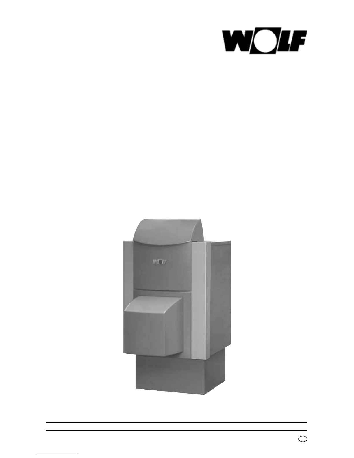
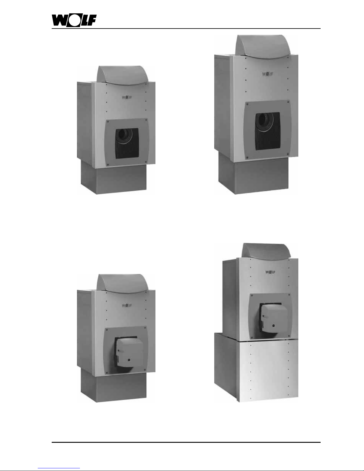
ComfortLine cast iron boilers
Oil and gas-red cast iron boilers, type
CHK
(boiler plinth, accessory)
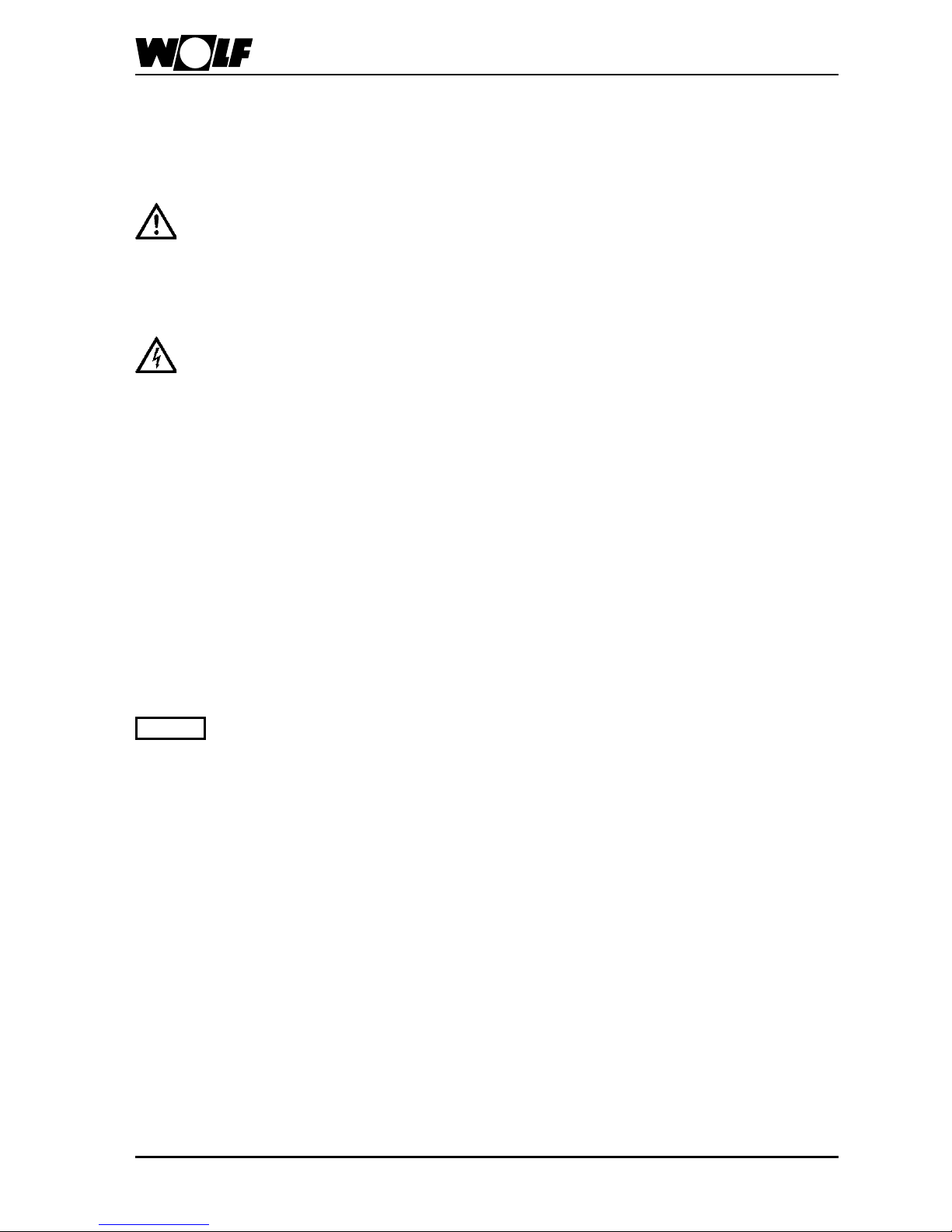
Oil and gas-red cast iron boilers, type
CHK-CB
incl. DHW cylinder
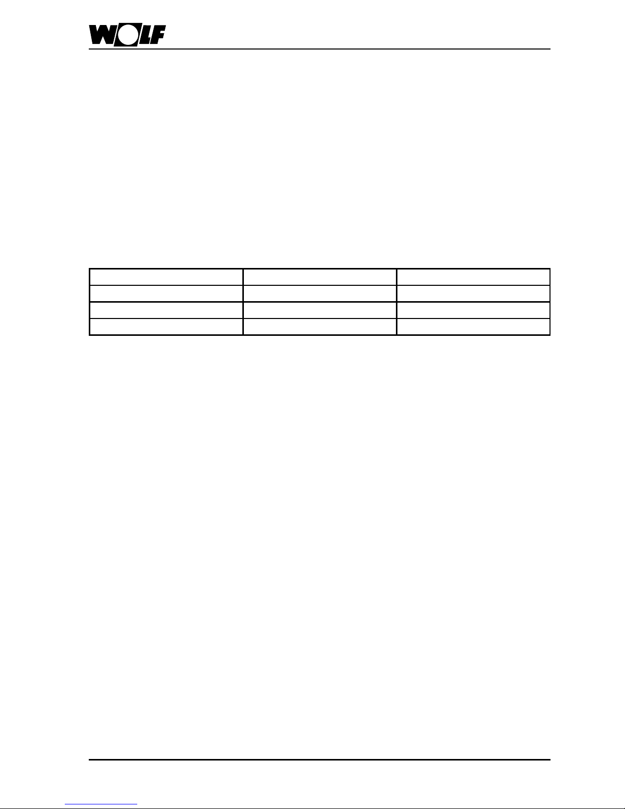
Oil-red cast iron Unit boiler, type CHU
incl. pressure jet oil burner
(boiler plinth, accessory)
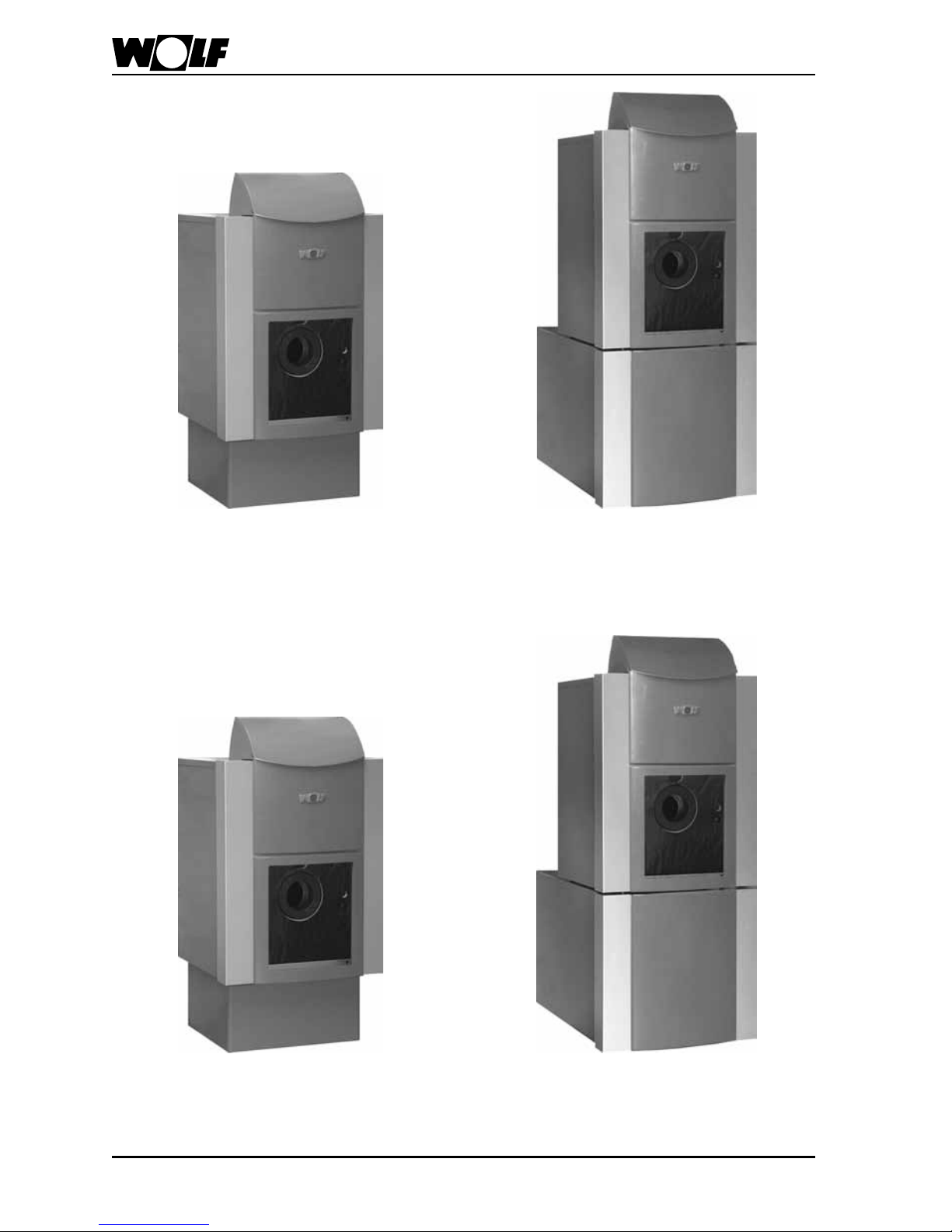
Oil-red cast iron Unit boiler, type CHU-CB
incl. DHW cylinder
and pressure jet oil burner
73060918_1203
FunctionLine cast iron boilers
Oil and gas-red cast iron boilers, type FHK
(boiler plinth, accessory)
Oil and gas-red cast iron boilers, type
FNK-FB/FE incl. DHW cylinder
Oil-red cast iron Unit boiler, type FHU
incl. pressure jet oil burner
(boiler plinth, accessory)
Oil-red cast iron Unit boiler, type FHU-FB/FE
incl. DHW cylinder
and pressure jet oil burner
8
3060918_1203
Installation
The ventilation air supply must
be ensured and comply with
local regulations or those relating to gas installations. We
recommend that you supply the
boiler with fresh air directly from
the outside. An insufcient fresh
air supply can lead to fuel gas
escaping, which represents
a risk to life (poisoning/suffocation).
Clearances towards walls and
combustible materials must
comply with local re regulations, and should be at least
200mm, otherwise there is a
high risk of re.
General tips regarding location
• Install the boiler with or without the
DHW cylinder on a level surface which
is substantial enough to carry its weight.
• Position the boiler and DHW cylinder (if
installed) horizontally or slightly rising
towards the back to ensure adequate
venting of any trapped air (level with
adjustable feet).
Only install the boiler and DHW
cylinder (if installed) in a room
safe from the risk of frost.
Drain the boiler, the DHW
cylinder and the entire heating
system if there is a risk of frost,
when the system has been
shutdown, to prevent pipes
from bursting.
Boilers should not be installed
in areas subject to aggressive
vapours, very dusty or highly
humid conditions (workshops,
washrooms, hobby rooms etc.).
This prevents the optimum
burner function from being
achieved.
The combustion air supplied to
the pressure jet oil burner must
be free from halogenated hydrocarbons (e.g. as contained
in sprays, solvents, cleaning
uids, paints and adhesives).
Under the most unfavourable
conditions, these may lead to
pitting of the boiler and even
the ue gas system.
Never store or use combustible
material or liquids near the
boiler.
Note
Note
93060918_1203
Installation
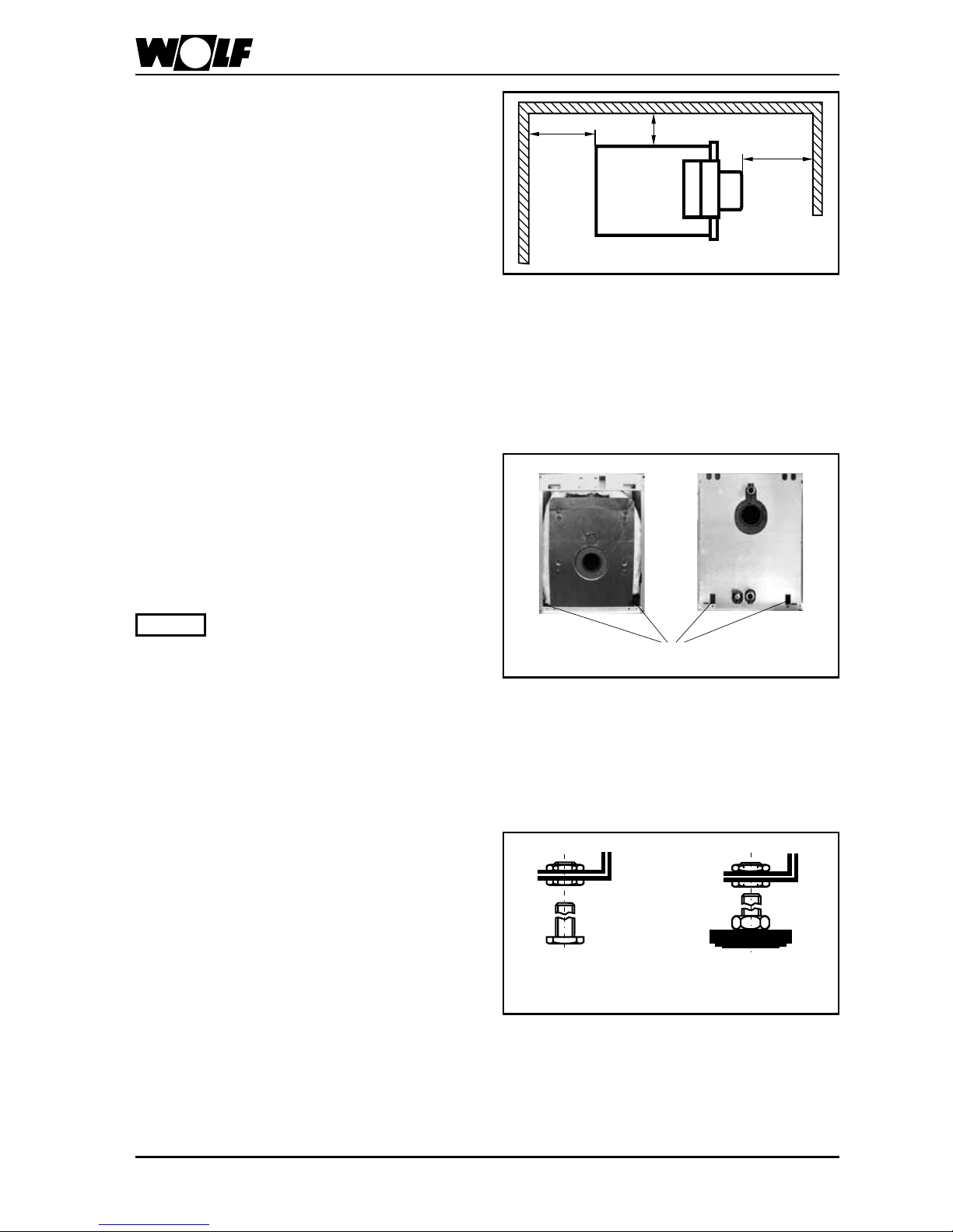
Recommended minimum wall
clearance
Maintain a minimum clearance between
the boiler sides and walls of 400 mm to
enable the boiler door with tted burner
to be opened.
Ensure that sufcient space is available
for cleaning and maintenance.
1000
900
400
Recommended minimum wall clearance
Transportation into the boiler
room
To ease the transportation into the boiler
room, lifting slings with lifting hooks are
offered as accessories.
Only lift the boiler using all four
lifting slings.
Note
Lifting eyes for lifting slings
Boiler installation on adjustable feet
At the factory the boiler is equipped with
four adjustable bolts
• Level the boiler with adjustable feet
(accessory) horizontally or with a slight
incline to the rear.
Feet
(accessory)
Adjustable
bolt
Adjustable bolt/ feet
10
3060918_1203
15
11 11
4
8
10
6 6
3
5
7
2
1
13
13
14
12
9
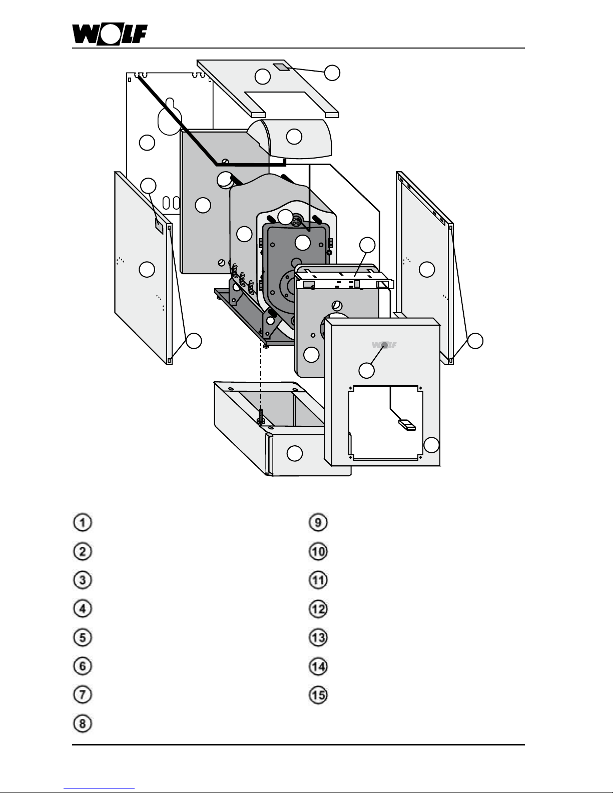
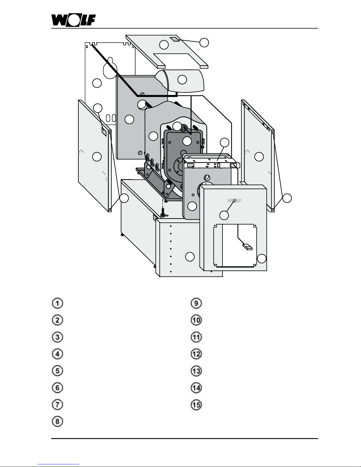
Boiler installation on a plinth
Boiler
Boiler door
Thermal insulation, boiler
Thermal insulation, boiler back
Thermal insulation, boiler front
Side casing
Control unit bracket
Back wall casing
Control unit housing
Casing cover
Spring shackles
Front casing
Type plate
Wolf logo
Plinth (accessory)
113060918_1203
15
11 11
4
8
10
6 6
3
5
7
2
1
13
13
14
12
9
Boiler installation on a horizontal
DHW cylinder
Boiler
Boiler door
Thermal insulation, boiler
Thermal insulation, boiler back
Thermal insulation, boiler front
Side casing
Control unit bracket
Back wall casing
Control unit housing
Casing cover
Spring shackles
Front casing
Type plate
Wolf logo
Horizontal DHW cylinder

12
3060918_1203
Boiler assembly
Boiler
• Install the plinth or the DHW
cylinder in accordance with the
enclosed installation instructions.
• Position the boiler with adjustab-
le bolts fully inserted using the
lifting slings on the fully assembled
plinth or DHW cylinder.
• To secure the boiler to the plinth
or DHW cylinder, tapped holes are
provided at the front sides of the
boiler. Additional xings are not
required.
• Check the horizontal level of the
boiler together with the plinth and
DHW cylinder and adjust, with a
slight incline to the rear, if necessary.
Screws for securing the boiler
Screws for securing the boiler to the plinth
Screws for securing the boiler
Fixing screws on the DHW cylinder
Position the thermal boiler
insulation
around the boiler (overlapping) and
secure with spring clips.
Position the thermal boiler insulation for the boiler back over the rear
connections and on the back wall of
the boiler.
Secure the boiler door
with the four M10x45 screws and
washers supplied.
Insert the door hinge pins into the
door bracket on the l.h. or r.h. side,
subject to door opening.
Boiler door installation
M10x45 screws

133060918_1203
Boiler assembly
Fixing plugs
Thermal insulation, boiler front
Thermal insulation, boiler front
Position the thermal insulation
loosely at the boiler front
and secure with xing plugs (4 no.).
Control unit bracket
Side casing
Hooks
Control unit bracket installation
Locate the control unit bracket
centrally and push parallel forward,
until both recesses in the side casing
click into the control unit bracket tabs.
and t the lower folded edge into
both notches of the boiler (view X).
Boiler notch
Lower folded edge of the side casing
View X
Side casing installation
Side casing
into the boiler front pushing the spring
clip
behind the boiler bracket
Side casing installation
Spring shackle
Bracket

14
3060918_1203
Boiler assembly
Locking tabs
Control unit bracket
Secure tightly
Control unit housing installation
Push the control unit housing
with locking tabs into the apertures
on the control unit bracket and pull
forward to its end stop. Secure the
control unit housing with the two
self-tapping screws supplied to the
control unit at the l.h. and r.h. rear,
working from top to bottom.
Route the boiler sensor to the front
and push into the sensor well in
any arrangement, then secure with
the circlip.
Rear wall installation
Back wall notches
Self-tapping screws
Locate the back wall casing
with tabs into the notches in the
side casing, and secure with the
self-tapping screws (4 no.) supplied.
Side casing xing screws
Self-tapping screws
Secure the control unit bracket and
side casing with the self-tapping
screws supplied (6 no.).

153060918_1203
Boiler assembly
Afx the type plate
in a clearly visible position.
Clip the Wolf logo
into the front casing
(only for FunctionLine).
Type plate / Wolf logo
Type plate
Wolf logo
Push the front casing
with open control unit lid with the
prole screws against the spring
shackles
, until they click into
place.
Front casing installation
Position the casing cover
onto both side casings and push
towards the control unit bracket.
Cable clip
Cover cap
Burner cable holder
Guide the burner cable through the
aperture in the control unit bracket
(l.h. or r.h. subject to boiler door
opening).
Clip a cover cap into the control unit
bracket to protect the burner cable.
Secure the cable clip with the burner
cable at the l.h. or r.h. side (bottom)
of the boiler.

16
3060918_1203
In addition, all ComfortLine boilers require
the following work to be undertaken.
ComfortLine decorative
panel installation
Decorative panel
Position the decorative panel with the
document wallet on the holes and push
against the front casing, until the clips
click into place.
Decorative panel installation
Decorative panel installation, single boiler
Decorative frame
(CHK 22-60 single boiler)
Click the plastic clips
(4 no., black) into
the front casing. Position the decorative
frame onto the clips and push down to
their end stop.

173060918_1203
ComfortLine decorative panel installation
Decorative frame
(CHU 22-29 Unit boiler)
With the dome at the top, push the silencer
hood into the decorative frame, then secure
the silencer hood with four self-tapping
screws from the inside to the decorative
frame.
Self-tapping
screws
Silencer hood
Decorative frame
Joining the decorative frame and the
silencer hood
Large silencer hood installation
Large silencer hood
(CNU 37-60 Unit boiler)
Click the plastic clips (4 no., orange)
into the front casing. Position the large
silencer hood onto the clips and push down
to their end stop.
Click both top plastic clips (black) from the
outside into the front casing. Click both
lower plastic clips (black) from the inside
into the front casing. Hook the decorative
frame with the silencer hood into the top
clips and secure in the lower plastic clips.
Decorative panel installation, Unit boiler

18
3060918_1203
FunctionLine decorative
panel installation
For models FHU-TH/22/29, the following
additional work should be undertaken.
Decorative panel
Click the plastic clips
(4 no., grey) into
the front casing.
Decorative panel installation
Decorative panel

193060918_1203
Flue pipe installation
Flue pipe silencer (accessory)
Install the ue pipe silencer with ue pipe
extension in accordance with the gure
shown.
Flue pipe
extension
Flue pipe
silencer
Flue pipe extension/silencer
Flue pipe outlet
Clean-out covers
Clean-out covers
in ue pipe elbows
• The ue pipe cross-section must match
that of the boiler ue outlet.
• Reducing the ue pipe size is only
permitted, if the satisfactory function
has been veried (by calculation) in
accordance with DIN 4705.
Keep the ue pipe as short as
possible and inclined towards
the chimney stack.
• Thoroughly seal in the ue pipe.
• Use ue pipe elbows with clean-out
covers to facilitate the cleaning of the
ue pipe.

20
3060918_1203
Central heating boiler connections
Central heating boiler connections
Boiler return
Connection for venting
and safety ow
Filling / Draining
Boiler return
Connect the heating ow and return to the
respective boiler ttings. For connections,
see below.
Install a check valve downstream of the
boiler circuit pump(s) to prevent incorrect
circulation.
Install a safety assembly comprising a safety valve with a
response pressure of 3 bar and
an automatic air-vent valve.The
pipework between the boiler
and the safety valve must not
be able to be shut off. Severely
excessive boiler pressure due to
excessive boiler temperatures,
can burst the boiler body or the
boiler pipework, which would
lead to a sudden excape of hot
water (risk of scalding).
Connect any underoor heating
system via a three or four-way
mixer.
Return temperature raising facility
Heating systems with large
water volume (above 20 litres
per kW output) require a return temperature of 30 °C, as
otherwise the longer heat-up
time of such systems would
create condensate and run an
increased risk of boiler body
corrosion.
Note
Provide system separation by
means of a heat exchanger,
when using pipes which are not
impermeable to oxygen.
This boiler is only suitable for
heating systems with pumped
heating circuits. If no heating
circuit pump has been installed,
sufcient circulation through the
radiators cannot be ensured,
putting the room heating in
question.
Recommendation: Convert
open systems into sealed
systems.
Note

213060918_1203
DHW cylinder to boiler pipework
Install the pipework between the boiler and the DHW cylinder in accordance with the
illustration below.
The DHW cylinder loading pump must supply from the top to bottom.
Note
Boiler return
Boiler ow
Hoses with gaskets
Sensor well for DHW
cylinder sensor
Cold water inlet
DHW circulation
DHW outlet
Filling / Draining
Cylinder loading pump
incl. gaskets
Ferrule with
union nut
Gravity brake
Elbows
DHW cylinder to boiler pipework

22
3060918_1203
Filling the heating system
Fill the system and vent it properly to safeguard the perfect boiler function.
Before connecting the boiler
to the heating system, ush
the entire system to remove
residues such as welding
pearls, hemp, putty, etc. from
the pipework.
The boiler and central heating
system may only be lled, if a
type-tested safety valve (opening pressure maximum 3 bar)
has been installed.
Note
Note
Filling the heating system
Connection for venting
and safety ow
Filling
• With the boiler in a cold condition, ll
the heating system slowly via the ll
and drain valve, until 1 bar pressure is
indicated. Inhibitors are not permissible.
Automatic air-vent valve
Locking cap
Automatic
air-vent valve
• Open the cap of the quick-action air-vent
valve of the safety assembly (accessory)
by one revolution, but do not remove
the cap.
Boiler ll and drain valve
Hose connection
• Connect a water hose to the lling/drain
valve (on-site).

233060918_1203
Filling the heating system
• Observe the pressure gauge of the
safety equipment assembly when lling
the system with water.
Safety assembly pressure gauge
Pressure gauge
• For boilers with DHW cylinder, vent
the heating coil at a system pressure
of approximately 0.50 bar or less by
starting the DHW cylinder loading
pump (operating time approximately 2
minutes).
• Check the entire system for water leaks.
• Check the safety valve function.
• Ventilate the boiler (e.g. via an automatic
air-vent valve).
• Fill the system to 1 bar pressure.
In operation, the pressure gauge must
indicate between 1 and 2.5 bar.
• Top up with water when the system
pressure falls severely.
• In constant mode, the boiler automati-
cally vents via the air-vent valve.

24
3060918_1203
Draining the heating system
Boiler ll and drain valve
Hose connection
Draining the heating system
Connection for venting
and safety ow
Drain
• Switch OFF the heating system (see
operating instructions) and let it cool
down to a maximum of 40 °C, to prevent
the risk of scalding.
• Open the drain tap on the boiler.
• Open the radiator bleed valves.
• Drain the heating water off.

253060918_1203
Pressure jet oil burner installation /
Electrical supply
Electrical supply
Do not route sensor leads with
230 V mains cables.
Connect the heating circuit pump(s) and
the DHW cylinder loading pump(s) on-site
via contactor, if:
• The burner and pump draw more than
2 A each.
• The total control unit power consumption
is exceeded.
Observe the control unit installation and
operating instructions.
Note
Electrical supply
Cable grommets
Pressure jet oil burner installation
The Unit pressure jet oil burner installation
instructions are included in the burner
packaging.
Only use bolts when securing
the burner to the boiler ange,
whose thread penetrates the
boiler ange by a maximum of
15 mm. Only use pressure jet
gas burners compliant with EC
Directive 90/396/EEC.
Boiler ange
Burner ange holes
1NT1 T2 S3 B4
BS MV
Burner plug wiring diagram

26
3060918_1203
Initial start-up
Only qualied personnel may
carry out the commissioning
and operation of the boiler
and the instruction of the
user.
• Check the boiler and system for leaks.
Close the water outlet - danger of
overheating and scalding.
• Check that all ue gas accessories have
been correctly installed.
• Open the shut-off valves on ow and
return.
• Switch ON the system ON/OFF switch
on the control unit.
Note:
When the heating system is started, the
display of the weather-compensated
control unit indicates all superuous (not
connected) sensors as fault messages.
For removing these fault messages see
the control unit operating instructions.
• If the system water pressure falls below
1.0 bar, top up with water until a pressure
of 1.0 to max. 2.5 bar has been achieved.
• An error code will ash in the display, if
the boiler/burner fails to start properly.
For details about error codes see the
quick-start operating instructions.
• Instruct the customer in the operation of
the boiler. Complete the commissioning
log and hand over the instructions.
• Position the operating instructions in
the boiler room where they are clearly
visible.
Saving energy
• Instruct the customer about energy-
savings options.
• Use this opportunity for reducing the
heating temperature night operation
using control accessories.
• Adjust the temperature so you are
comfortable; every degree of room temperature reduction will achieve energy
savings of up to 5%.
• Reduce the room temperature in unoc-
cupied rooms as far as possible; please
observe frost protection.
• Ensure that all thermostatic radiator
valves are fully opened in rooms where
room thermostats are installed.
The room thermostat must not be ob-
structed by furniture or curtains.
Function checks
• During commissioning, check all control,
regulating and safety equipment for their
correct function and settings.

273060918_1203
Commissioning report
Commissioning steps
Test values and
conrmation
1.) Water connections checked for leaks?
2.) Vented boiler and system?
3.) System pressure 1 - 2.5 bar?
4.) Function test carried out?
5.) Flue gas test:
Gross ue gas temperature
___________
tA [°C]
Ventilation air temperature
___________
tL [°C]
Net ue gas temperature
_______
(tA - tL ) [°C]
Carbon dioxide content (CO2) or oxygen content (O2)
______________
%
Carbon monoxide content (CO), free of air
____________
ppm
6.) Casing tted?
7.) System user trained, technical documents handed over?
8.) Conrm commissioning

28
3060918_1203
Maintenance
Note:
To ensure the reliable and safe function
of a heating system, users are required to
have it checked and cleaned on an annual
basis by an approved heating contractor
(check local regulations). Switch OFF the
boiler when cleaning the boiler room.
We would recommend a maintenance
contract.
Front casing
Front casing removal
• Switch OFF the heating system (see
operating instructions) and let it cool
down.
• Remove the front casing from the boiler.
• Pull the burner plug.
• Release the boiler door screws.
Boiler door screws
Boiler door removal

293060918_1203
Maintenance
Turbulators
Pulling out the turbulators
• Open the boiler door.
• Pull out the turbulators.
Cleaning using the cleaning brush
• Remove soot/sulphur deposits with the
cleaning brush supplied.
• Assemble in reverse order.

30
3060918_1203
Maintenance log
• Please tick the maintenance steps carried out and enter the test values into this log.
Maintenance steps Date Date
1. Cleaned the boiler?
2. Leak test carried out during operation?
3. Function test carried out?
4. Flue gas test:
Gross ue gas temperature tA [°C] ________ tA [°C] ________
Ventilation air temperature t
L
[°C] ________ tL [°C] ________
Net ue gas temperature (t
A
- tL ) [°C] ____ (tA - tL ) [°C] ____
Carbon dioxide content (CO
2
) or % ___________ % ___________
Oxygen content (O
2
) % ___________ % ___________
Carbon monoxide content (CO), free of air ppm _________ ppm _________
5. Conrm maintenance
(company stamp, signature)

313060918_1203
Maintenance log
Date Date Date Date
tA [°C] ________ tA [°C] ________ tA [°C] ________ tA [°C] ________
t
L
[°C] ________ tL [°C] ________ tL [°C] ________ tL [°C] ________
(t
A
- tL ) [°C] ____ (tA - tL ) [°C] ____ (tA - tL ) [°C] ____ (tA - tL ) [°C] ____
% ___________ % ___________ % ___________ % ___________
% ___________ % ___________ % ___________ % ___________
ppm _________ ppm _________ ppm _________ ppm _________

32
3060918_1203
Specication
* Values for upper/lower boiler output, relative to a CO2 content of 13 % (fuel oil EL) and
an average boiler water temperature of 60 °C. The chimney stack dimensions must
be calculated in accordance with DIN 4705. For ue gas temperatures below 160 °C,
connect the boiler to highly insulated chimney stacks (heat conductivity resistance
class I acc. to DIN 18160 T1) or suitable, moisture-resistant ue gas systems, which
have been type-approved.
CHK / FHK / CNU-Premio / CHU-TH / FHU-TH 22 22
CHK-CB / FHK-FB / FHK-FE / CHU-Premio-CB
CHU-TH-CB / FHU-TH-FB / FHU-TH-FE
22/155 22/200
Output rangeexcl. burner, incl. TH burner kW 15-221 5-22
incl. Premio burner kW 19-22 19-22
Set-up burner output kW 21 21
DHW cylinder capacity CB & FB / FE litres 155/150 200
Constant DHW cylinder output CB & FB litres/h 540 540
FE litres/h 540 540
Performance factorCB & FB NL60 2.8 4.4
FE NL60 2.8 4.1
Number of boiler sections 3 3
Water content litres 29 29
Boiler gas content litres 33 33
Heating water pressure drop (at ∆T=20K) mbar 2 2
Maximum permissible boiler pressure bar 4 4
Maximum permissible DHW cylinder pressure bar 10 10
Rel. standby losses Boiler % 1.15 1.15
Boiler+DHW cylinder % 1.7 1.9
Required boiler draught Pa 10 10
Flue gas temperature* ° C 130/170 130/170
Flue gas mass ow rate* kg/h 25/37 25/37
Boiler, safety ow (female thread) Rp 1¼“ 1¼“
Boiler return (female thread) Rp 1¼“ 1¼“
Filling, draining, safety return (female thread) Rp ½“ ½“
Flue pipe diameter mm 129 129
Combustion chamber depth mm 350 350
Combustion chamber diameter mm 290 290
Weight Boiler kg 167 167
Burner kg 10 10
CHW cylinder CB and FB kg 66 83
DHW cylinder FE kg 98 121
Electrical supply
Maximum current (control unit and accessories)
Maximum current (in total, excluding pumps)
Switching capacity pumps, mixer, burner
Control unit fuse (maximum current)
Optional connection for mixer motors

333060918_1203
Specication
29 29 37 45 60
29/155 29/200 37/200 45/200 60/200
22-29 22-29 29-37 37-45 48-60
25-29 25-29 29-37 37-45 48-59
27 27 34 41 55
155/150 200 200 200 200
710 710 910 1100 1225
710 710 910 940 940
3.1 4.6 4.8 4.9 5.0
3.1 4.3 4.5 4.5 4.5
4 4 5 6 8
35 35 41 47 59
43 43 53 63 83
4 4 6 8 14
4 4 4 4 4
10 10 10 10 10
1.05 1.05 0.95 0.85 0.7
1.6 1.8 1.6 1.4 1.2
13 13 16 19 0
140/170 140/170 150/170 150/170 155/175
37/49 37/49 49/62 62/75 80/100
1¼“ 1¼“ 1¼“ 1¼“ 1¼“
1¼“ 1¼“ 1¼“ 1¼“ 1¼“
½“ ½“ ½“ ½“ ½“
129 129 149 149 149
450 450 550 650 850
290 290 290 290 290
198 198 229 260 322
10 10 15.5 15.5 15.5
66 83 83 83 83
98 121 121 121 121
230 V / 50 Hz / 10A
5 VA
15 VA
230 V, 4(2) A each
M 6.3 A
230V, 50Hz, optimum time 4 - 7 minutes

34
3060918_1203
C
B
D
A
E
F
2
G
H
J
F
1
C
B
D
A
E
G
H
J
Dimensions
Observe the height of adjustable feet/bolts 20 mm ±10mm.
CHK / FHK / CHU-Premio
CHU-TH / FHU-TH
22 29 37 45 60
Boiler height A mm 835 835 835 835 835
Width B mm 660 660 660 660 660
Length C mm 640 740 840 940 1040
Plinth height D mm 280 280 280 280 280
Overall height incl. control unit E mm 1280 1280 1280 1280 1280
Silencer hood depth F
1
mm 336 336 345 345 345
Burner hood depth F
2
mm 235 235 235 260 275
Central heating return G mm 397 397 397 397 397
Smoke tube connector H mm 859 859 859 859 859
Central heating ow J mm 997 997 997 997 997

353060918_1203
C
B
D
A
E
F
2
H
K
J
L
M
G
F
1
C
B
D
A
E
H
K
J
L
M
G
Dimensions
Observe the height of adjustable feet/bolts 20 mm ±10mm.
CHK-CB / FHK-FB / FHK-FE / CHU-Premio-CB
CHU-TH-CB / FHU-FB / FHU-FE
37 45 60 45 60
Boiler height A mm 835 835 835 835 835
Width B mm 660 660 660 660 660
Length of 155 l DHW cylinder C mm 987 987 - - Length of 200 l DHW cylinder C mm 1262 1262 1262 1262 1262
DHW cylinder height D mm 625 625 625 625 625
Overall height incl. control unit E mm 1625 1625 1625 1625 1625
Silencer hood depth F1 mm 336 336 345 345 345
Burner hood depth F2 mm 235 235 235 260 275
Central heating return G mm 742 742 742 742 742
Smoke tube connector H mm 1204 1204 1204 1204 1204
Central heating ow J mm 1342 1342 1342 1342 1342
Cold water inlet K mm 90 90 90 90 90
CB/FB DHW circulation L mm 412 412 412 412 412
FE DHW circulation L mm 312 312 312 312 312
DHW connection M mm 534 534 534 534 534

36
3060918_1203
Troubleshooting
Fault Cause Remedy
Burner does not start or
enters a fault state
No voltage present at the
control unit
Fuse, electrical connections,
Check the position of the ON/
OFF switch and heating sys.
emergency stop switch.
Oil tank empty / Gas supply
line shut off
Fill oil tank /
Open gas supply line.
Burner fault Press the reset button at
burner control unit
(see burner installation
instructions)
Safety temperature Press the reset button at the
control cut-out activated unit.
Oil lter clogged Replace oil lter.
Heating circuit pump does
not start
System in summer mode Check summer/winter switch
position.
Heating circuit pump locked upTurn the pump shaft with a
screwdriver.
Heating circuit pump faulty Replace the heating circuit
pump.
Cylinder loading pump does
not run
DHW cylinder thermostat
faulty
Check DHW cylinder thermostat and replace, if necessary.
Cylinder loading pump seized upTurn the pump shaft with a
screwdriver.
Cylinder loading pump faulty Replace the DHW loading
pump.
Heating system operational,
but room temperature too low
Adjust maximum boiler temperature set too low.
Raise maximum boiler temperature.
Heat-up takes too long Heating water temperature
too low
(check at DHW cylinder ow,
not at the boiler)
Raise the temperature
(adjust thermostat)
Too little heating water
(creates wider spread, i.e. return
temperature too low)
Install larger DHW cylinder
loading pump
Indirect coil not vented Vent indirect coil with loading
pump OFF
Indirect coil scaled up Descale indirect coil
DHW temperature too low Thermostat switches OFF too
soon
Adjust thermostat
Return temperature too low
(e.g. spread too wide)
Return temperature too low
(e.g. spread too wide)
 Loading...