

1
Installation
and
Operating instructions
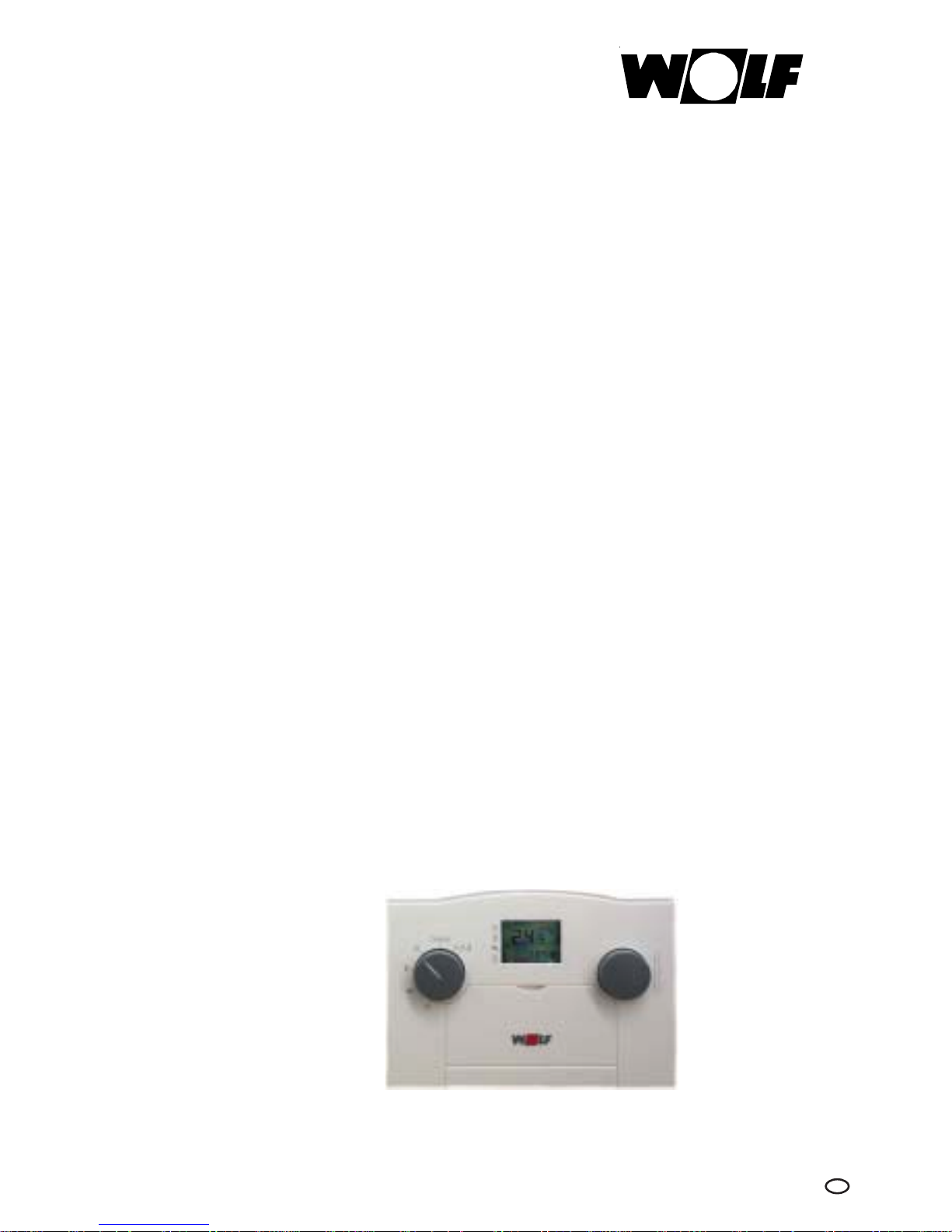
ART
Analog room thermostat
with day program
for gas fired boilers
Nr. 8610015
Technology serving mankind
Part no. 30 48 400 Subject to technical modifications 6.6701.621
Wolf GmbH · Postfach 1380 · 84048 Mainburg · Tel. +49 8751/74-0 · Fax +49 8751/741600 · Internet: www.wolf-heiztechnik.de
03/06 TV GB

2
Index
Index ...........................................................................................................................Page
Summary of functions ....................................................................................................................... 3
Terminology / Standards and regulations ...................................................................................... 4
Installation ............................................................................................................................................ 5
BUS interface setting ......................................................................................................................... 5
Electrical connection ......................................................................................................................... 6
Program selector.................................................................................................................................. 7
Temperature selection – heating mode ......................................................................................... 7
Status display ....................................................................................................................................... 7
Setting the time ................................................................................................................................... 8
Summer/winter.................................................................................................................................... 8
Economy temperature........................................................................................................................ 8
Day program setting............................................................................................................................ 9
1 x DHW................................................................................................................................................. 9
Contractor level ........................................................................................................................10 - 11
Accessories .........................................................................................................................................12
Specification.......................................................................................................................................12
3
NCN
N
N
i
B
NCN
N
N
i
B
i
C
B
Bi
q
C
B
q
C
N
N
i
B
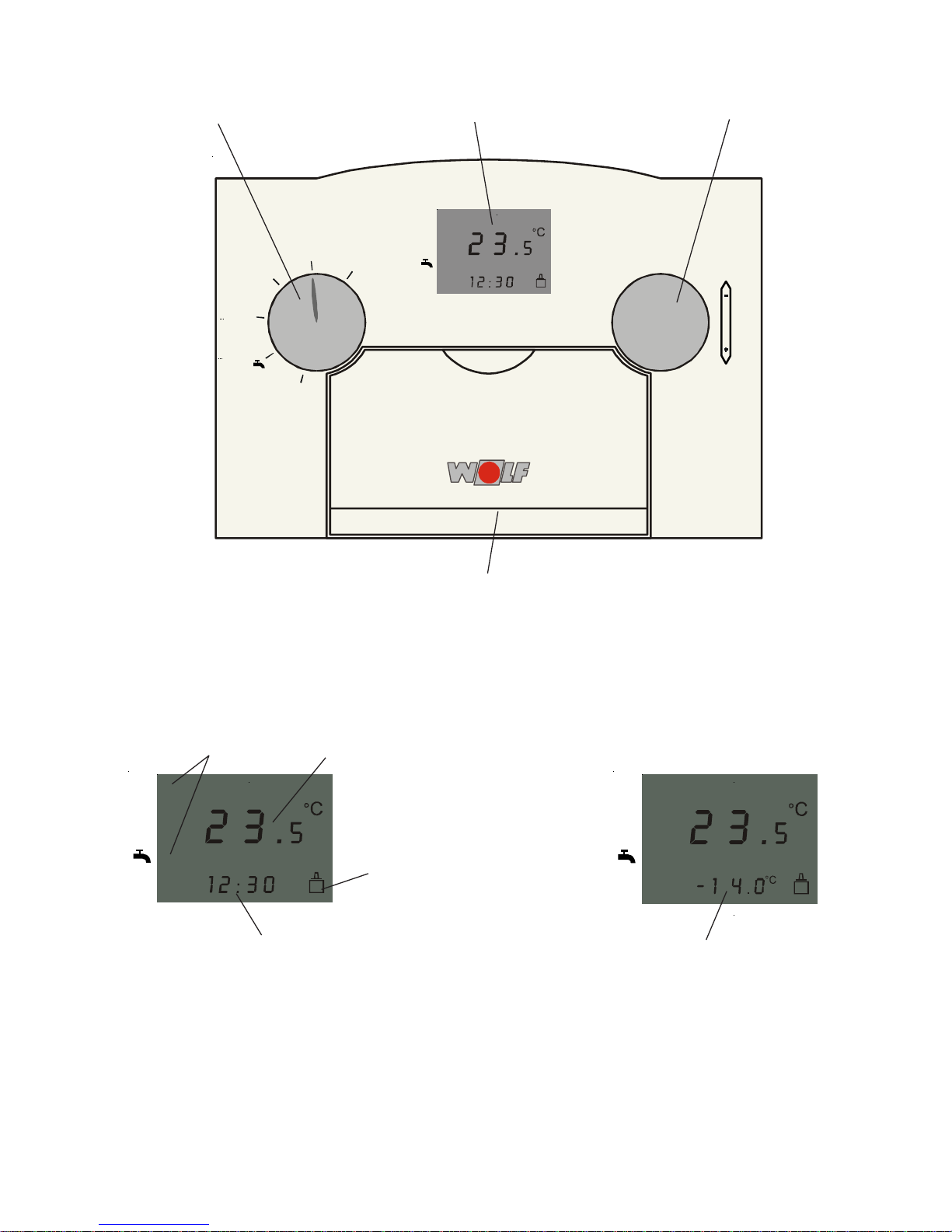
Summary of functions
Front flap
Program selector Temperature selection – heating modeDisplay
Standard display
Status display Room temperature display
Time
Outside temperature (with connected
outside temperature sensor)
The outside temperature display changes
with the time display in 10 s intervals
BUS connection

4
In gas fired combination boilers, the analog
room thermostat ART complies with the
following Directives:
- Low Voltage Directive: 73/23/EEC
- EMC Directive: 89/336/EEC
Terminology / Standards and regulations
Standards and regulations
Terminology
Heating water temperature
The heating water temperature is the radiator
flow temperature. The higher the heating water
temperature, the higher the heat transfer to
radiators.
Boiler
Gas fired boiler, which can be combined with a
DHW cylinder.
Combination boiler
Gas fired boiler with an instantaneous water
heater and DHW QuickStart.
DHW loading
Heating up the DHW cylinder.
DHW QuickStart
The heating water in the boiler will be held at
a certain temperature during summer mode,
to be able to supply hot water as rapidly as
possible from the instantaneous water heater
of the combination boiler. The day program
switches this function ON and OFF during
summer mode.
Heating program
Subject to program selection, the day program
switches the gas fired boiler from heating to
economy mode or from heating mode to
heating OFF and vice versa.
Domestic hot water program
In a combination boiler, the day program
controls the DHW QuickStart, and for a boiler
with a DHW cylinder, it switches the cylinder
loading ON and OFF.
Winter mode
Central heating and DHW according to the
day program.
Summer mode
Central heating OFF, DHW according to the
day program.
Heating mode/economy mode
In winter mode, two room temperatures can
be selected. One for central heating mode and
one for economy mode, when the room
temperature will be setback to economy
temperature.
The day program changes over between
heating and economy mode.

5
Installation
- Install the ART on an internal wall at a height
of approx. 1.5 m.
- Install the ART in a living room, which is
representative of the entire living
accommodation.
- The ART must not be subject to draughts or
radiated heat.
- The ART must not be blocked by furniture or
curtains.
- In this room, all radiator valves must be fully
opened.
Installation / BUS interface setting
Remove the ART from its base using a screwdriver
- Lever the ART top from its base using a
screwdriver .
In doing so, insert the screwdriver into the
lower cutout of the base, and lever the base
at the terminal strip.
- Secure the base through the fixings holes.
3
1526
4
+ -
Fixing holes
Plug to the
top part
Telecontrol contact
Connection
data cable
e-BUS or
SCOM
Please note: All accessory controllers (BUS users) must be set to the same boiler interface.
Wolf boilers are equipped either with an e-BUS or a SCOM interface for control accessories. The
interface can be selected with the DIP switches on the back of the ART.
BUS interface setting
For boilers with eBUS interface, the BUS
terminals are marked “+“ and “-“ together with
“eBUS“.
The interface address for eBUS is set at the
factory (DIP switch 4 is set to “ON“, switches 1
to 3 are set to “OFF“).
Connection to Wolf boilers with eBUS interface
For boilers with SCOM interface, the BUS
terminals are marked “+“ and “-“ in accordance
with connection diagrams together with
“(Wolf) Accessory“ (DIP switches 1 to 4 are set
to “OFF“).
Connection to Wolf boilers with SCOM interface
Accessory
Accessory

6
3
1526
4
+ -
Plug to the
top part
Telecontrol contact
for eBUS and SCOM
Connection
data cable
e-BUS or SCOM
The electrical connection must only be carriedThe electrical connection must only be carried
The electrical connection must only be carriedThe electrical connection must only be carried
The electrical connection must only be carried
out by a qualified electrician.out by a qualified electrician.
out by a qualified electrician.out by a qualified electrician.
out by a qualified electrician.
Do not Do not route these cables with mains
supply cables.
Electrical connection
Wire the ART with 2-core cable (minimum crosssection 0.5 mm²) to the gas fired boiler. Subject
to boiler terminal strip, select one of the adjacent
wiring diagrams.
Warning
Replace the ART onto its base and click into place.
When refitting the housing ensure, that the
contact pins on the thermostat are not bent.
Terminal strip inside the ART base
ART terminal
strip
Terminal strip
on the gas
fired boiler
Connection version a)
ART terminal strip
Terminal strip
on the gas
fired boiler
1 2
+ -
Zubehör
+
-
a
b
AF
24VAC 24VDC
Connection version b)
ART terminal strip
Terminal strip
on the gas
fired boiler
1 2
+ -
Zubehör
!
+
-
a
b
AF
24V
0V
24VDC24VDC
Connection version c)
1 2
+ -
ab+
A
AF
F
24 V
E1
eBUS
Accessory
Accessory

7
Program selector / heating temp. selection mode / status display
i
C
B
B
i
q
CB
q
Operating
mode
Program
display
Central
heating
Domestic hot water
Boiler
Domestic hot water
Combination boiler
Central heating OFF /
Frost protection
Summer
mode
Central heating OFF /
Frost protection
Economy mode
Heating mode
Heating or economy mode
acc. to the day program
Heating mode or central
heating OFF acc. to the
day program
DHW loading OFF,
DHW cylinder frost
protection ensured
DHW cylinder loading
acc. to the day program
DHW loading OFF,
DHW cylinder frost
protection ensured
Enable DHW loading
DHW cylinder loading
acc. to the day program
DHW cylinder loading
acc. to day program
DHW QuickStart
OFF
Winter
mode
DHW QuickStart acc.
to the day program
Standby
Important: For gas fired boilers with pro-
gram
selector, this must be set to .
Program selector (l.h. rotary selector)
ART program selector
B
i
q
C
B
q
B
Heating mode active
Economy mode active
DHW loading or DHW QuickStart
enabled
Central heating OFF (frost protection)
and DHW loading or DHW QuickStart
OFF
Status (display)
C
i
NCN
N
N
i
B
Arrows displaying the current
operating status
Heating mode temp. selection (r.h. rotary selector)
Turning the selector changes the display from
current room temperature to set room
temperature.
Then you can change the desired room
temperature for heating mode. If no change is
made after more than 2 s, the display will again
show the current room temperature.
Temperature selection –
heating mode
Central heating OFF /
Frost protection

8
Setting time / summer/winter / economy temperature
Setting the time / changing from
summer to winter or vice versa
Note: When using a radio clock module, setting
the time and summer/winter changes are made
automatically.
Open the front flap on the ART controller to
set the current time or to change from summer
to winter time or vice versa.
After pressing the time key the display
changes to the time setting mode. Now adjust
the time with the r.h. rotary selector.
The standard display will be shown again if no
changes are made after more than 10 s or one
of the three keys is pressed.
Program selector Temperature selection – heating modeDisplay
DIP switch
Time key
Economy temperature key
Contractor level key
Reset button
q
Setting the economy temperature
After pressing the economy temperature key
the display changes to the setting mode
for the required room temperature in economy
mode.
The current set temperature for economy mode
will be displayed.
Turning the r.h. rotary selector (heating mode
temperature selector) changes this value.
The standard display will be shown again if no
changes are made after more than 10 s or one
of the three keys is pressed.
C

9
Day program setting / 1 x DHW
0
12h
12 18 24h14
C
BB
C
108426
222016
Reset
q
C
1
x
i
i
/
/
DIP switch
1 x DHW Contractor level
0
12h
12 18 24h14
C
BB
C
108426
222016
Reset
q
C
1
x
i
i
/
/
Day program example
Heating ON from 06.00 - 22.00 h
Heating OFF/economy from 22.00 - 06.00 h
For boilers with DHW cylinder loading
enabled from 6.00 - 22.00 h
DHW cylinder loading disabled
from 22.00 - 06.00 h
q
C
1
x
Key combination for “1 x DHW“
NCN
N
i
B
Display during “1 x DHW“
Day program setting
Day programs for central heating and DHW
cylinder loading (for boilers with DHW
cylinders) or DHW QuickStart are set using the
DIP switches under the front flap.
Heating mode settings and enabling DHW
cylinder loading/DHW QuickStart: push the DIP
switch up for the required period.
The set room temperature for heating mode
will be used.
Economy mode or central heating OFF (subject
to the program selector setting):push the DIP
switches for the required period down .
The selected set room temperature for economy
mode is used or the central heating is switched
OFF. DHW loading or DHW QuickStart are
disabled.
The shortest switching period is 30 minutes.
Note: The day program settings will only
be active, if the program selector has
been set in accordance with the day
program , or .
B
i
q
C
B
q
C
i
/
B
q
1 x DHW
If DHW is required outside the period where
DHW loading is enabled, the DHW cylinder can
be heated to the set temperature by means of
function “1 x DHW“. Pressing keys and
simultaneously either activates or deactivates
this function. In the activated state, a flashing
arrow appears on symbol . Function “1 x
DHW“ will be deactivated automatically after
one hour.

10
Parameter mode
e.g. gradient
Display mode
e.g. actual flow
temperature
Contractor level
Pressing key changes the display to contractor
level.
The contractor level is segregated into display
and parameter mode.
Individual displays (e.g. A:01) and parameters
(e.g. P:01) are shown in sequence after
pressing .
In parameter mode you can change the values
displayed above the r.h. rotary selector.
Display list:
Index Explanation Unit
A 01 Set flow temperature °C
A 02 Actual flow temperature °C
A 03 Actual DHW temperature °C
Parameter list
Index Explanation Setting range Factory setting
P 03 Set DHW temperature 15 - 65 °C for boilers type E 60 ° C
40 - 63 °C for boilers type K 60 °C
P 04 Pasteurisation 00 - 01 0 0
GB 01 Flow temperature hysteresis 1 - 20
GB 04 Upper fan speed - central heating 30 - 100
GB 0 5 Frost protection outside temperature -10 - 10
GB 0 6 Heating circuit pump mode 0 - 1
GB 07 Heating circuit pump run-on 1 - 30
GB 08 Maximum set flow temperature 40 - 90
GB 09 Cycle block 0 - 30
GB 13 Input 1 0 - 5
GB 14 Output 1 0 - 9
GB 15 DHW cylinder hysteresis 1 - 15
List of displays and parameters
Note: Parameters GB01 to GB15 are not avaliable for all boilers; for descriptions see the
installation instructions of the relevant boiler.
Contractor level
Parameters GB 01 - 15 must only be modified by a heating contractor . Incorrect operation
can lead to system faults.
Parameter 5 (outside temperature frost protection) is only effective with an outside
temperature sensor .
Warning
See installation
instructions for
gas fired boiler

11
Pasteurisation (P 04) (only with eBUS
in conjunction with a boiler with DHW
cylinder)
Pasteurisation is switched OFF when factory
settings are active (parameter P 04 = 00).
Pasteurisation is active if parameter P 04 is set
to 01.
The DHW cylinder will be heated to 65 °C once
every day for one hour after DHW loading has
been enabled, if pasteurisation has been
activated.
Parameter P 04 will be displayed during eBUS
communication.
Contractor level
Automatic summer and winter
changeover
The ART will automatically change over to
summer mode (heating circuit pump is switched
OFF), if the room temperature rises 1K above
the set room temperature. The system
automatically reverts to heating mode (heating
circuit pump is switched ON), when the actual
room temperature falls below the set room
temperature. Note: In summer mode, the status
display shows or .
Controller reset
The ART processor is restarted by pressing
“Reset“. The display indicates the software
number, version and all symbols in sequence.
Loading the standard configuration
Hold down key and briefly press “Reset“. The
software number and version and then EEP
are displayed. The ART is then reset to its factory
settings.
i
Set DHW temperature (P 03)
Setting the desired DHW temperature for eBUS
interfaces.
For SCOM interfaces, the DHW temperature will
only be displayed. Adjustments are made at the
boiler.
i
Fault code Explanation
91 Wrong address set - ART
Fault code display
Fault code 91: In systems with several controllers,
two (e.g. AWT, ART) are set to the same BUS
address. Correct the address settings using the
DIP switches on the respective controllers.
Check the installation instructions of the
respective boiler for an explanation of all other
fault codes.
If the device will not operate properly after the
boiler has been reset twice, or if the boiler
cannot be reset, inform your heating
contractor of the fault code displayed.
Fault codes
Any fault of the gas fired boiler will be
indicated by a flashing fault code number and
the warning symbol in the ART display.
NCN
N
N
i
B
q
Room temperature dependent frost
protection
Heating mode commences with a set room
temperature of +5 °C if the room temperature
in summer mode drops below 5 °C. The frost
protection functions ends if the actual room
temperature rises above +6 °C. Even during
frost protection, the status display remains
at .

12
Specification
Supply voltage 18 VDC ±15%
Power consumption max. 1VA
Protection according to DIN 60529 IP30
Protection class according to VDE 0100 III (max. 24V)
Time switch power reserve min. 10 h
Permissible ambient temperature in use 0 to 50 °C
Permissible ambient temperature during storage -30 to +60 °C
Communication and power supply via 2-core cable, interchangeable (cross-section 0.5mm2)
to the gas fired boiler
Telecontrol module
By connecting a telecontrol module, the heating
and the DHW mode can be activated via
telephone, excluding the influence of the time
channel. Note the installation and operating
instructions of the telecontrol module for
connection and settings.
Telecontrol module (part no. 27 91 044)
Radio clock module (only eBUS)
The ART time is adjusted via a ratio signal
received by the radio clock module [where
available].
The changeover between summer and winter
time too is regulated by radio signal [where
available].
Radio clock module (part no. 27 92 321)
Accessories / Specification
 Loading...