

Wolf AGE24 Service Manual

SERVICE MANUAL
Heavy Duty Gas Griddles
MODEL
924RE ML-135221-00G24
936RE ML-135222-00G36
948RE ML-135223-00G48
960RE ML-135224-00G60
972RE ML-135225-00G72
www.vulcanhart.com
MLS
924RE
AGE24
ITW Food Equipment Group, LLC
3600 North Point Blvd.
Baltimore, MD 21222
MODELS
AGE24 ML-135226-00G24
AGE36 ML-135227-00G36
AGE48 ML-135228-00G48
AGE60 ML-135229-00G60
AGE72 ML-135230-00G72
www.wolfrange.com
FORM F-35628 (Rev. 8-07)
MLS

TABLE OF CONENTS
INSTALLATION
COMPONENT LOCATION .......................................................................................................................5
948RE AND AGE48 CONTROL PANEL
CONTROL PANEL ............................................................................................................ 6
BULLNOSE ...................................................................................................................... 6
HEAT SHIELD .................................................................................................................. 7
BACK PANEL ................................................................................................................... 7
THERMOSTAT .........................................................................................................................................7
THERMOSTAT TROUBLESHOOTING
SYMPTOM – NO POWER TO THE BURNER SOLENOID ......................................................8
SYMPTOM – GRIDDLE SURFACE TEMPERATURE IS MORE THAN ±15°F OF
THERMOSTAT SET POINT .....................................................................................................8
THERMOSTAT REMOVAL
THERMOSTAT CALIBRATION .......................................................................................... 9
POWER ON/OFF SWITCH.....................................................................................................................10
POWER SWITCH TROUBLESHOOTING
SYMPTOM – NO POWER BEING SUPPLIED TO THE UNIT ...............................................10
POWER SWITCH REMOVAL
INDICATOR LIGHT.................................................................................................................................10
INDICATOR LIGHT TROUBLESHOOTING
SYMPTOM – LIGHT DOES NOT COME ON WHEN THERMOSTAT AND BURNER ARE ON
................................................................................................................................................10
INDICATOR LIGHT REMOVAL
FLAME SWITCH.....................................................................................................................................11
FLAME SWITCH TROUBLESHOOTING
SYMPTOM – INDICATOR LIGHTS AND BURNER VALVES NOT WORKING .....................12
HELPFUL HINT.......................................................................................................................12
FLAME SWITCH REMOVAL
HELPFUL HINT.......................................................................................................................12
SPARK IGNITER MODULE....................................................................................................................12
SPARK IGNITOR TROUBLESHOOTING
SYMPTOM – NO SPARK BETWEEN PILOT HEAD AND ELECTRODE...............................13
SYMPTOM – ELECTRODE CONTINUALLY SPARKS AFTER PILOT IS LIT........................13
SPARK IGNITOR REMOVAL
SOLENOID VALVES ..............................................................................................................................13
SOLENOID VALVE TROUBLESHOOTING
SYMPTOM – NO GAS FLOW TO BURNER ..........................................................................14
SOLENOID VALVE REMOVAL……………………………………………………………………… 14
PILOT VALVE.........................................................................................................................................14
PILOT VALVE TROUBLESHOOTING
SYMPTOM – PILOT WILL NOT LIGHT ..................................................................................14
PILOT ASSEMBLY REMOVAL
HELPFUL HINT.......................................................................................................................15
BURNER.................................................................................................................................................15
BURNER TROUBLESHOOTING
SYMPTOM – ALL BURNERS HAVE A LOWER OR HIGHER FLAME THAN NORMAL .......16
SYMPTOM – ONE OR MORE BURNERS HAVE LOWER FLAME LEVEL THAN THE
OTHERS. ................................................................................................................................16
........................................................................................................................... 4
.............................................................................. 5
............................................................................... 8
................................................................................................ 8
.......................................................................... 10
........................................................................................... 10
....................................................................... 10
........................................................................................ 11
........................................................................... 12
............................................................................................ 12
.......................................................................... 13
........................................................................................... 13
........................................................................ 14
............................................................................... 14
......................................................................................... 15
...................................................................................... 16
-
2 -

SYMPTOM – ONE BURNER HAS A DELAYED IGNITION; A SEVERAL SECOND LAPSE
BETWEEN THE INDICATOR LIGHT TURING ON AND WHEN THE BURNER ACTUALLY
LIGHTS. ..................................................................................................................................16
BURNER REMOVAL
BURNER ADJUSTMENT ................................................................................................. 16
GAS REGULATOR.................................................................................................................................17
REGULATOR TROUBLESHOOTING
SYMPTOM – UNIT WILL NOT MAINTAIN CONSISTENT PRESSURE.................................18
GAS PRESSURE MEASURMENT .........................................................................................................18
SEQUENCE OF OPERATION................................................................................................................19
FROM THE INSIDE OUT........................................................................................................................19
WIRING DIAGRAMS ..............................................................................................................................20
WIRING DIAGRAM – 24-INCH GRIDDLE
WIRING DIAGRAM – 36-INCH GRIDDLE.......................................................................... 21
WIRING DIAGRAM – 48-INCH GRIDDLE.......................................................................... 22
WIRING DIAGRAM – 60-INCH GRIDDLE.......................................................................... 23
WIRING DIAGRAM – 72-INCH GRIDDLE.......................................................................... 24
....................................................................................................... 16
................................................................................ 18
.......................................................................... 20
-
3 -

GENERAL
INTRODUCTION
This manual is prepared for the use of trained service technicians and should only be used by those
who are properly qualified. This manual is not intended to be all encompassing. You should read, in
it's entirety, the repair procedure you wish to perform to determine if you have the necessary tools,
instruments and skills required to perform the procedure. Procedures for which you do not have the
necessary tools, instruments and skills should not be attempted.
Disconnect the electrical power and follow lockout / tagout procedures
Certain procedures in this manual require electrical test or
measurements while power is applied to the machine. Exercise extreme caution at all
times when attempting these procedures. Before testing, disconnect electrical power
and follow lock/out tagout procedures, then attach test equipment and reapply power to
test.
Procedures in this manual will apply to all 900RE and AGE models unless specified. No procedure
in this manual will require the removal or raising of the griddle plate. Pictures and illustrations can be of
any model unless the picture or illustration needs to be model specific.
INSTALLATION
Generally, installations are made by the dealer or contracted by the dealer or owner. Detailed
installation instructions are included in the Installation and Operation Manual that is sent with each unit.
However, it should be noted that an improperly installed unit, especially an unlevel unit can lead to
premature electrical component failures. A unit that is higher in the front will cause the flue gases to
vent improperly and gather in the front near the electrical components. All 900RE and AGE models
must be installed with an externally mounted regulator.
OPERATION
Detailed operation instructions are included in the Installation & Operation Manual sent with each
unit and are also available at WWW.VULCANHART.COM
CLEANING
Detailed cleaning procedures are included in the Installation & Operation manual sent with each
unit.
LUBRICATION
No lubrication is required on this equipment.
SPECIFICATIONS
All 900RE and AGE models operate on 120 volt, 60 hertz, single phase at 0.5 amps. All models are
equipped with electric snap-action thermostats, automatic spark igniters and pilot flame safety switches.
All models are equipped with 30,000 BTU/HR burners as standard equipment. One burner is used for
every 12 inches of griddle surface. Natural gas models are to operate at 5.0" W.C. manifold pressure
and LP models at 10.0" W.C. manifold pressure with main burners on.
.
-
4 -
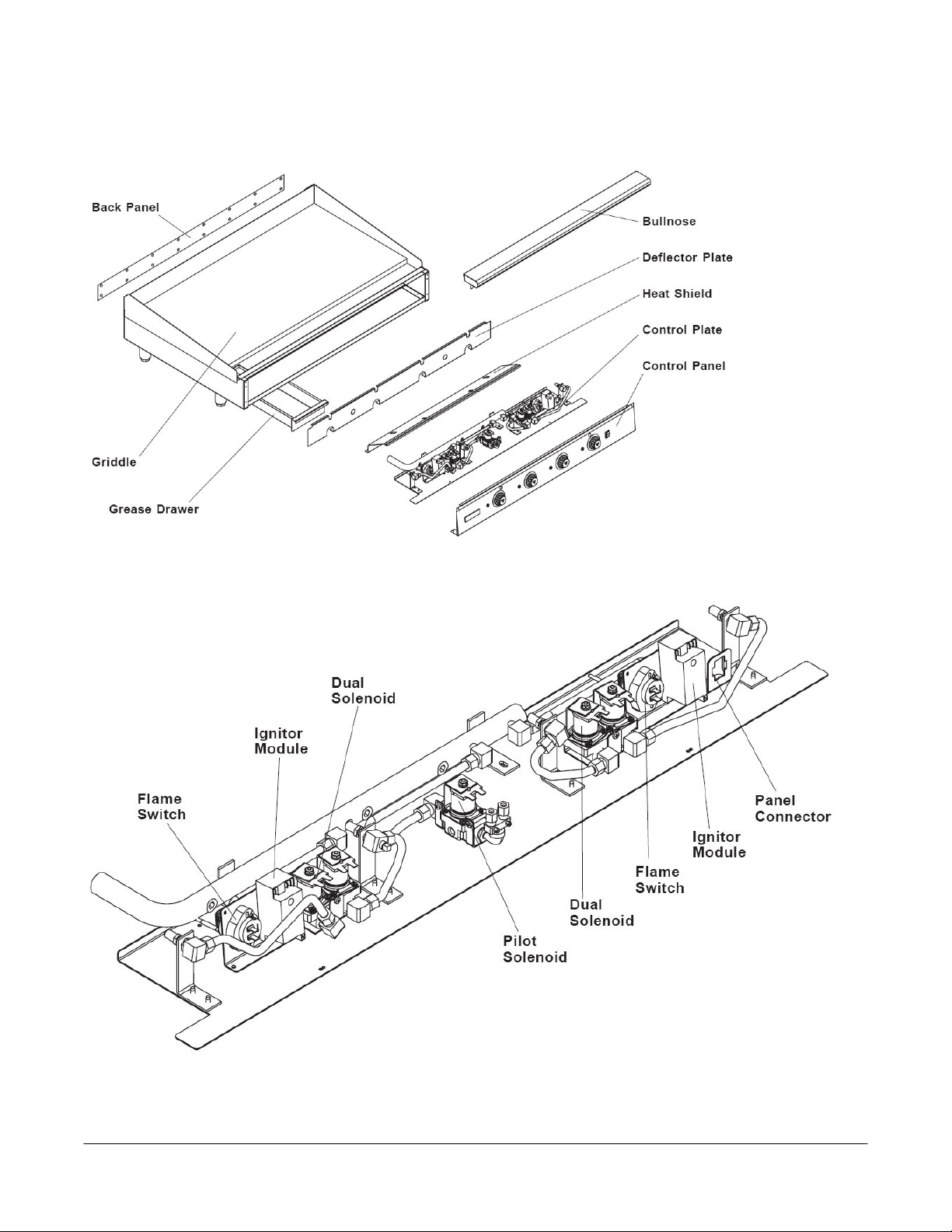
COMPONENT LOCATION
948RE AND AGE48 CONTROL PANEL
-
5 -
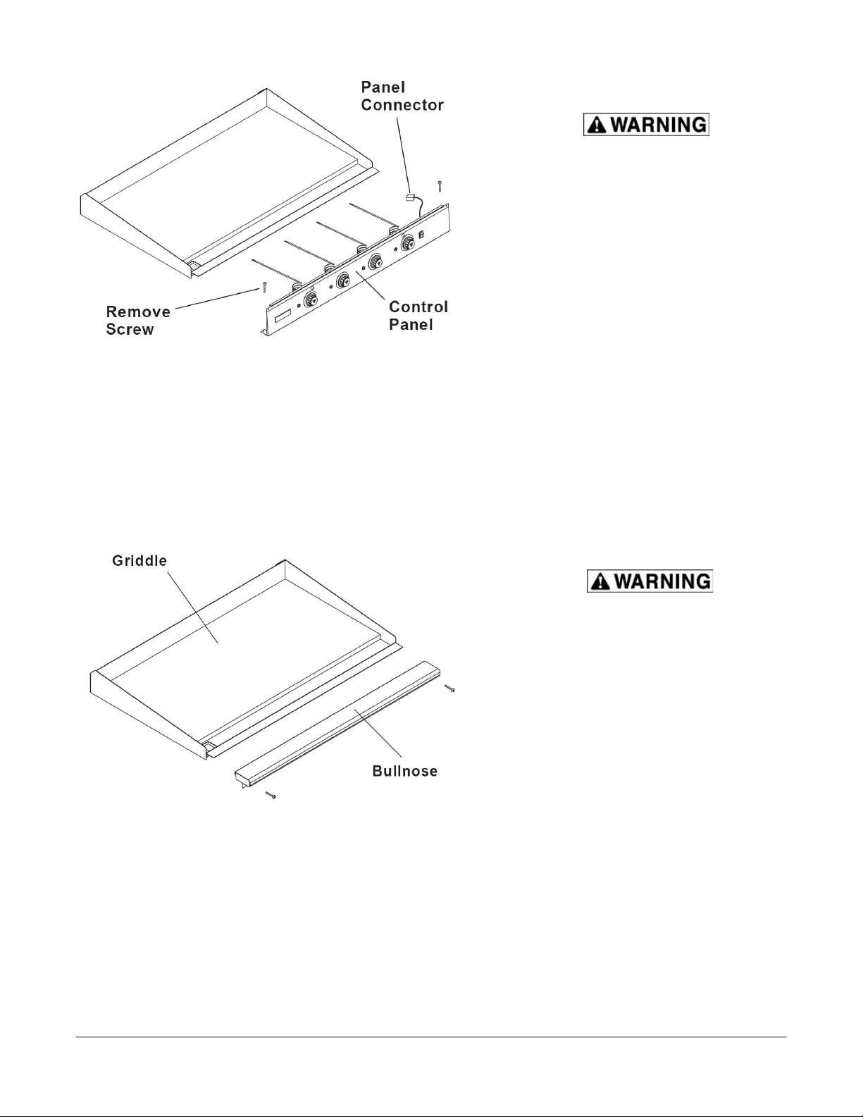
CONTROL PANEL
Disconnect the electrical
power and follow lockout
/ tagout procedures
The Control Panel holds the
thermostats, indicator lights
and power switch, and is
connected to the Control
Plate with a Panel Connector
1. Remove the four screws
securing the control
panel. There are two
screws at each end of the
panel.
2. Pull the control panel
forward and disconnect
the electrical panel
connector near the right
end.
3. Reverse the procedure to
install.
BULLNOSE
Disconnect the electrical
power and follow
lockout / tagout
procedures
The Bullnose acts as a front
rail or shelf during griddle
operation.
1. Remove the Control
Panel.
2. The bullnose assembly is
secured with several
screws, one each end of
the bottom of the
assembly and several
more (depending on
size) facing the griddle
plate.
3. Reverse the procedure
to install.
-
6 -
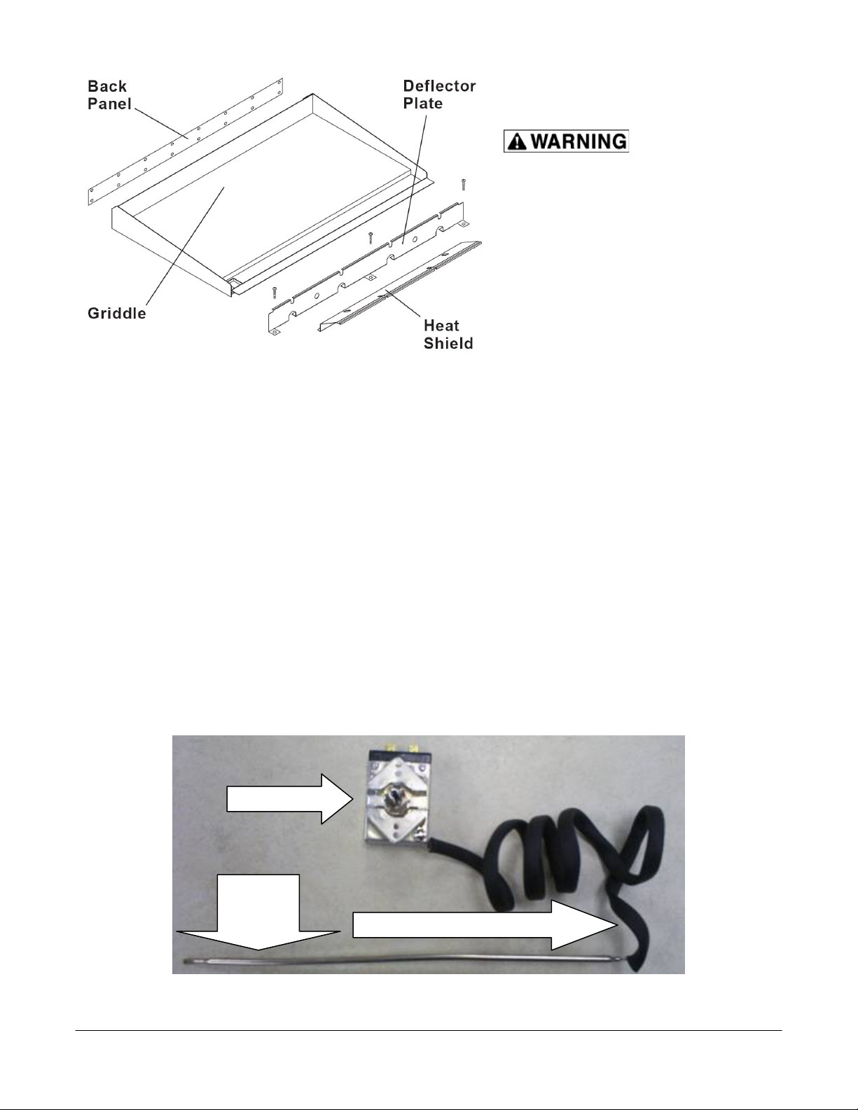
HEAT SHIELD
Disconnect the
electrical power and follow
lockout / tagout procedures
The heat shield protects the electrical
components and should only be
temporarily removed for easier
replacement of some the control
components.
1. Remove the control panel.
2. Remove screws along the top edge
that secure the heat shield.
3. The shield clamps on the front of the
chassis and can be removed by
grasping the top of the shield and
pulling forward.
BACK PANEL
It should only be necessary to remove the back panel when changing a burner or to remove
excessive grease build up from the flue area.
1. Disconnect gas supply at griddle.
2. Remove all screws from rear of griddle securing the back panel.
3. Reverse the procedure to install.
THERMOSTAT
Thermostat
Capillary
bulb
The thermostat is a snap action, single pole – single throw type. The thermostat supplies power to
the main burner solenoid valves when turned on or until the temperature set point is reached.
Capillary wire insulation
-
7 -

Disconnect the electrical power and follow lockout / tagout procedures
THERMOSTAT TROUBLESHOOTING
SYMPTOM – NO POWER TO THE BURNER SOLENOID
1. Check for loose or excessively greasy/dirty connections at terminals
2. Check for continuity/resistance between the two thermostat terminals with wires disconnected
A. If you get continuity/resistance with the thermostat off or open – replace thermostat
B. If you do not get continuity or resistance with thermostat on or closed – replace
thermostat
3. Check flame switch for continuity/resistance and voltage
4. Check for voltage from hot line
A. If no voltage check wiring for shorts or breaks
SYMPTOM – GRIDDLE SURFACE TEMPERATURE IS MORE THAN ±15°F OF THERMOSTAT SET
POINT
1. Ensure that you are using a high quality, calibrated surface temperature measuring device.
A. Do not use an infrared thermometer – these are highly inaccurate on a griddle plate.
B. Refer to instructions on the proceeding page for proper placement of probe and method.
2. Check that burners are properly adjusted.
3. Check that burner valves are operating correctly.
4. Check that there are no burner orifice obstructions
5. Check that thermostat capillary bulb is completely seated back as far as possible in the groove
on the bottom of the plate. No part of the bulb should be exposed from behind the bulb heat
shield.
6. Check that the high temp. capillary wire insulation is completely covering capillary wire from the
connection at the thermostat to the beginning of the bulb and that the insulation is not damaged
or burned thru. If insulation appears damaged – replace the insulation.
7. If you have found no problems in steps 1 – 6, proceed to the next page for calibration
instructions.
8. If thermostat will not calibrate after all previous steps – replace thermostat.
THERMOSTAT REMOVAL
1. Remove the control panel
2. Remove the knob
3. Label and disconnect the wires
4. Remove the two screws and two washers securing the thermostat dial and thermostat to the
Control panel.
5. Remove the heat shield.
6. Pull the capillary bulb straight out from the plate groove.
7. Reverse the procedure to install while ensuring that capillary bulb is completely seated – all the
way to the back of the plate groove.
8. Check that capillary wire is completely covered with insulation from the connection at the
thermostat to the beginning of the sensor bulb.
-
8 -
 Loading...