

Page 1
WOLF 30''(762) AND 36''(914) CONVECTION MICROWAVE
TRIM KIT INSTALLATION INSTRUCTIONS (808663)
Wolf Microwave Trim Kits for
MWC Model:
MWCTRIM 30/ SST (808745)
MWCTRIM 30/ BK (808746)
MWCTRIM 30/ PLM (808747)
MWCTRIM 36/ SST (808748)
MWCTRIM 36/ BK (808749)
MWCTRIM 36/ PLM (808750)
The Wolf Convection Microwave Oven MWC 24 can be
installed above Wolf Single Ovens; SO30F/S, SO30U/B,
SO30U/P, SO30U/S, SO36U/B, SO36U/P or SO36U/s.
The cabinet or wall rough in dimension must be within the
following specification (See fig. A & B on page 2):
30''(762)
36''(914)
Height: 18 11/16''(475) 18 11/16''(475)
Width: 27 1/2''(699) 33 3/8''(854)
Depth: 20 1/8''(511) 20 1/8''(511)
NOTE: Please read these instructions thoroughly
before beginning installation.
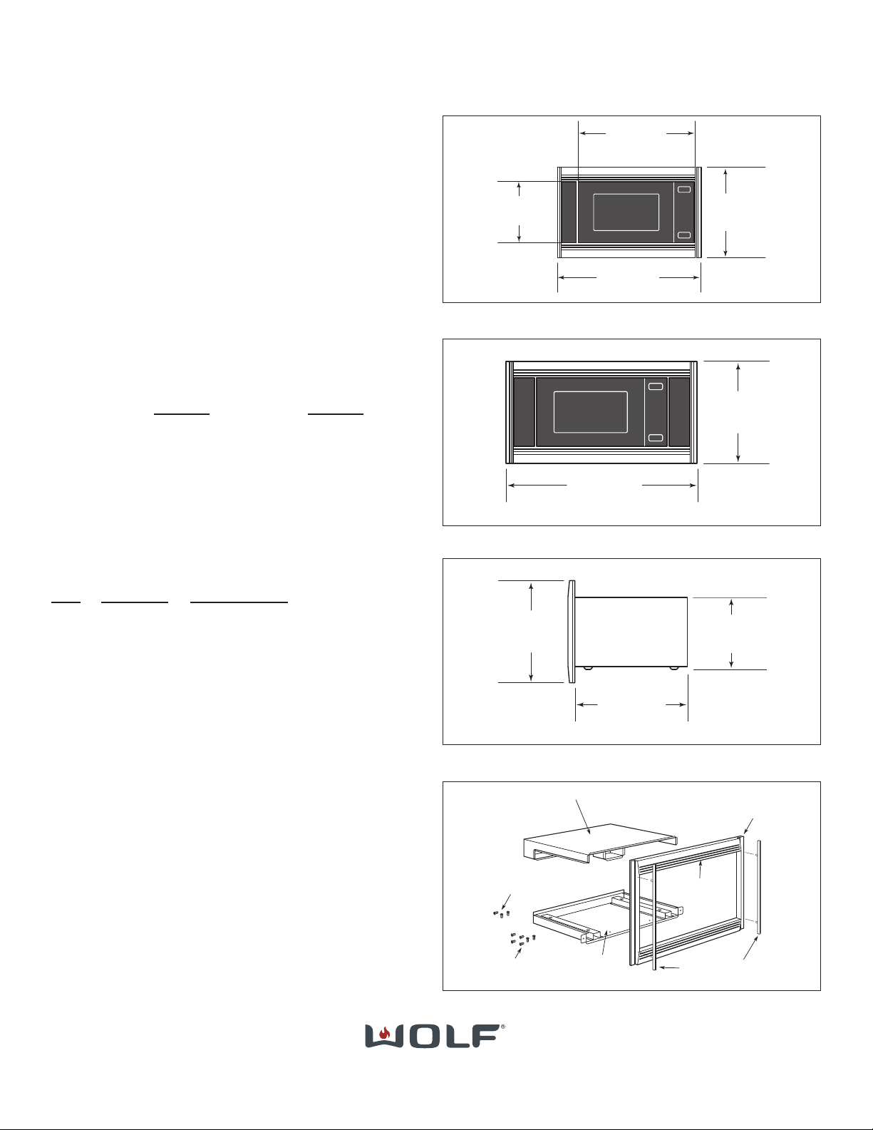
Parts Included with Microwave Trim Kit
(See Fig. Microwave Kit Contents):
QTY
PART NO. DESCRIPTION
1 806052 Top Duct Work Assembly
1 806053 Bottom Duct Work Assembly
1 805953-S 30''MWC Trim
806046-B 30''MWC Trim
806047-P 30''MWC Trim
1 805954-S 36''MWC Trim
806048-B 36''MWC Trim
806049-P 36''MWC Trim
2 805949 30''Brackets, Glass Assembly
805950 36''Brackets, Glass Assembly
6 802684 Screws, Mounting Brackets (Cabinet)
6 805187 Screws, Mounting Brackets (Trim)
2 808566-RT Mounting Brackets
808567-LT Mounting Brackets
808663 / Rev D / June 2008
297/8"
(759)
30" (762) TRIM WIDTH
243/4"
(629)
FREESTANDING
WIDTH
19 7/8"(505)
TRIM
HEIGHT
FREESTANDING
HEIGHT
14 7/8"(378)
Free Standing and 30'' Trim Overall Dimensions
TRIM
HEIGHT
35
11
/
16 " (906)
36" (914) TRIM WIDTH
19 7/8 (505)
36'' Trim Overall Dimensions
30'' and 36'' Side Trim Dimensions
19 7/8"(505)
TRIM
HEIGHT
14 7/8"(378)
FREESTANDING
HEIGHT
201/8"
(511)
BEHIND FRAME
Microwave Trim Kit Contents
MWC TRIM
MOUNTING
SCREWS
BRACKET, GLASS ASSEMBLY
TOP DUCT WORK ASSEMBLY
BOTTOM DUCT
WORK ASSEMBLY
ASSEMBLED TRIM
KIT
TOP DUCT WORK
SCREWS
Page 1 of 3
Wolf Appliance, Inc. P.O.Box44848 Madison, WI 53744 800-332-9513 www.wolfappliance.com
Page 2
WOLF 30''(762) AND 36''(914) CONVECTION MICROWAVE
TRIM KIT INSTALLATION INSTRUCTIONS (808663)
808663 / Rev D / June 2008Page 2 of 3
Dimensions in parentheses are in
millimeters unless otherwise specified.
251/2"
min
(648)
26"
min (660)
CABINET DEPTH
*Dimension may vary by
+_
1
/8" (3).
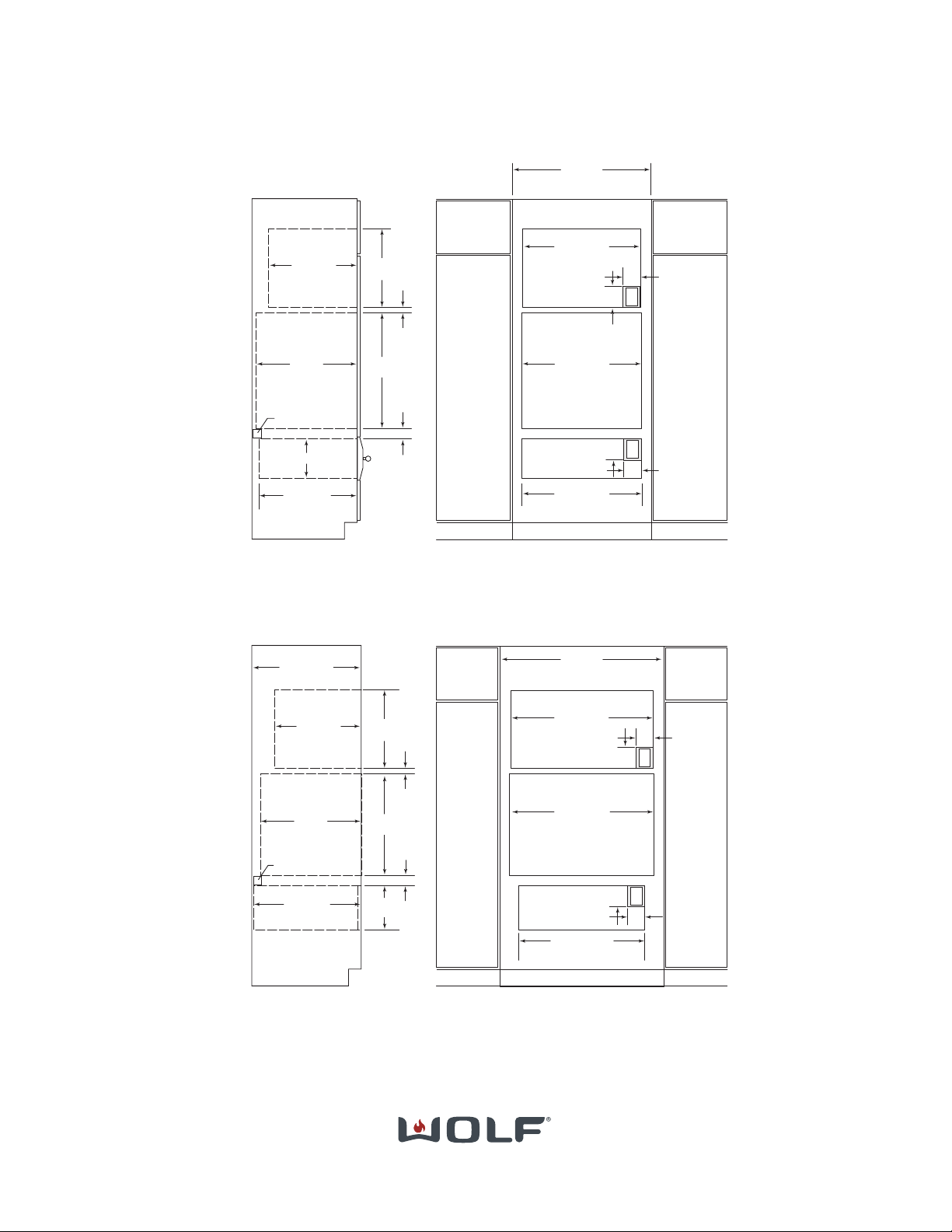
**Refer to installation instructions provided with the integrated drawer front (WDFRONT/I) for accurate placement of the anti-tip block.
NOTE: Refer to the built-in 36" (914) single oven specifications for electrical location.
NOTE: The width of the custom panel for the warming drawer with integrated drawer front will vary according to the specific installation,
but the rough opening width will remain 29
15
/16" (760).
NOTE: At installation, wood cleats must be added to the openin
for the microwave trim.
23/8"
(60)
103/8"*
(264)
333/8"
(854)
MICROWAVE
OPENING WIDTH
24"
min
(610)
241/16"
(611)
341/2"
(876 )
36-INCH OVEN
OPENING WIDTH
5"
(127)
4"
(102)
E
39"
(991)
RECOMMENDED CABINET WIDTH
36"
min (914)
1"
min
(25)
201/8"
min
(511)
1811/16"
(475)
2"
(51) x 2"(51)
ANTI-TIP BLOCK**
E
5"
(127)
4"
(102)
2915/16"*
(760)
WARMING DRAWER
OPENING WIDTH
281/2"
(724)
WARMING DRAWER
OPENING WIDTH
281/2"
(724)
30-INCH OVEN
OPENING WIDTH
5"
(127)
4"
(102)
E
9
1
/4"
(235)
23/8"
(60)
231/2"
min
(597)
273/16"
(691)
1"
min
(25)
24"
min
(610)
33"
(838)
RECOMMENDED CABINET WIDTH
30"
min (762)
271/2"
(699)
MICROWAVE
OPENING WIDTH
201/8"
min
(511)
1811/16"
(475)
5"
(127)
4"
(102)
E
NOTE: Refer to the built-in 30" (762) single oven specifications for electrical location.
NOTE: At installation, wood cleats must be added to the openin
for the microwave trim.
2"
(51) x 2"(51)
ANTI-TIP BLOCK
INSTALLATION SPECIFICATIONS
Convection Microwave with 30" (762) Trim
Installation with single oven and warming drawer
INSTALLATION SPECIFICATIONS
Convection Microwave with 36" (914) Trim
Installation with single oven and warming drawer
Fig.
A
Fig.
B
Wolf Appliance, Inc. P.O.Box44848 Madison, WI 53744 800-332-9513 www.wolfappliance.com
Page 3

PROCEDURE:
Step 1
A. Place microwave on bottom duct
assembly (See Fig. 1).
B. Assemble top duct as shown in
Figures 2, 3 and 4.
C. Remove existing screw from
upper right and left rear of
microwave (See Fig. 6).
D. Place top duct cover assembly on
microwave. Reinsert existing
screws through assembly into
original screw holes (See Fig. 6).
Step 2
A. Attach mounting brackets as
shown in Fig. 5 with provided
screws. Make sure brackets do
not extend beyond the front surface of the cabinet. Always be
sure to pre-drill pilot holes before
installing screws to avoid damage
to cabinet or trim kit hardware.
Install MWC24 with a 120V, 60Hz, on
a dedicated circuit. This outlet must
be checked by a qualified electrician
to see if it is wired with correct
polarity and is correctly grounded.
A GFCI outlet is not recommended
as this may cause product operation
interruptions.
WOLF 30''(762) AND 36''(914) CONVECTION MICROWAVE
TRIM KIT INSTALLATION INSTRUCTIONS (808663)
Wolf Appliance, Inc. P.O.Box44848 Madison, WI 53744 800-332-9513 www.wolfappliance.com
808663 / Rev D / June 2008
Page 3 of 3
BOTTOM DUCT
WORK ASSEMBLY
Figure 1
Figure 2
Figure 4
Figure 3
Figure 6
Figure 7
Step 3
A. Place oven adjacent to wall or
cabinet opening. Plug power cord
into electrical outlet.
B. Carefully guide complete assem-
bly between bottom cleats and
push assembly back. When both
top and bottom duct work are
assembled and correctly placed,
their flanges will be tight against
top and bottom outer edge of
opening (See Fig. 6).
C. Secure bottom duct work assem-
bly with two mounting screws
(805187) for trim. Avoid pinching
cord between oven and wall
(See Fig. 8).
D. Carefully place assembled trim kit
on oven. Check that it is level and
secure with 4 mounting screws
(805187) for trim (See Fig. 9).
E. Push decorative panels into slots
until they snap into place.
Figure 8
Figure 9
Mounting
Bracket Screws
(802684)
Figure 5
Use for Trim > 1 1/8”
Deep
Use for 1” Deep Trim
 Loading...