

Wohler ATSC/DVB-3 User Manual

ATSC/DVB-3
2U Digital Stereo Speaker Monitor
(Document P/N 821507, Rev-D)
with AC-3 and AES/EBU Inputs on
XLR and BNC, Selected Digital to Analog
Outputs on XLR, Six 53-Segment
Level Meters, and Phase Indication
User Manual
CONTENTS
Title and Contents ........................................................
Introduction ..........................................................................
Section 1: Features, Specs, and Installation ......
Description and Features .......................................................
Applications and Specifications ..............................................
Installation .............................................................................
Section 2: Operation ....................................................
Front Panel Features ..............................................................
Rear Panel Features ...............................................................
Audio Amplifier and Speaker Configuration ...........................
Balance Control Characteristics ..............................................
Section 3: Technical Information ............................
General Technical information ...............................................
1
2
3
4
5
6
7
8
12
14
14
15
16
Level Meter Description and Specifications.................................
ATSC/DVB-3 Block Diagram ..................................................
© 2005 Wohler Technologies Inc. ALL rights reserved
17
18
1

Important Safety Instructions
1) Read these instructions.
2) Keep these instructions.
3) Heed all warnings.
4) Follow all instructions.
5) Do not use this apparatus near water.
6) Clean only with dry cloth.
7) Do not block any ventilation openings. Install in accordance with the manufacturer's instructions.
8) Do not install near any heat source such as radiators, heat registers, stoves, or other apparatus (including
amplifiers) that produce heat.
9) Do not defeat the safety purpose of the polarized or grounding-type plug. A polarized plug has two blades
with one wider than the other. A grounding type plug has two blades and a third grounding prong. The
wide blade or the third prong are provided for your safety. If the provided plug does not fit into your outlet,
consult an electrician for replacement of the obsolete outlet.
10) Protect the power cord from being walked on or pinched, particularly at plugs convenience receptacles
and the point where they exit from the apparatus.
11) Only use attachments/accessories specified by the manufacturer.
12) Use only with the cart stand, tripod, bracket, or table specified by the manufacturer, or sold with the
apparatus. When a cart is used, use caution when moving the cart/apparatus combination to avoid injury
from tip-over.
13) Unplug this apparatus during lightning storms or when unused for long periods of time.
14) Refer all servicing to qualified service personnel. Servicing is required when the apparatus has been
damaged in any way, such as when power-supply cord or plug is damaged, liquid has been spilled or
objects have fallen into the apparatus, the apparatus has been exposed to rain or moisture, does not
operate normally, or has been dropped.
15) Do not expose this apparatus to rain or moisture.
16) The apparatus shall be connected to a mains socket outlet with a protective earthing connection.
CAUTION!
In products featuring an audio amplifier and speakers, the surface at the side of the
unit, where the audio amplifier heat sink is internally attached, may get very hot after
extended operation. When operating the unit excercise caution when touching this
surface and ensure that external materials which may be adversely affected by heat
are not in contact with it. There is a Hot Surface label (see diagram) attached to the
aforementioned surface of the product.
Introduction
Congratulations on your selection of a Wohler Technologies product. We are confident it represents the best performance and value
available, and we guarantee your satisfaction with it.
If you have questions or comments you may contact us at:
Phone: (510) 870-0810 Fax: (510) 870-0811
www.wohler.com support@wohler.com
2
© 2007 Wohler Technologies, Inc. ALL rights reserved
Wohler Technologies, Inc.
31055 Huntwood Avenue
Hayward, CA 94544
US Toll-Free: 1-888-596-4537

ATSC/DVB-3 User Manual P/N 821507 Rev-D
General Features, Specifications,
and Installation
General Specifications
Sect. 1: General Features and Specifications
Section 1
Description
Features
Applications
Installation
© 2005 Wohler Technologies Inc. ALL rights reserved
3
ATSC/DVB-3 User Manual P/N 821507 Rev-D
Section 1: General Features, Specifications, and Installation
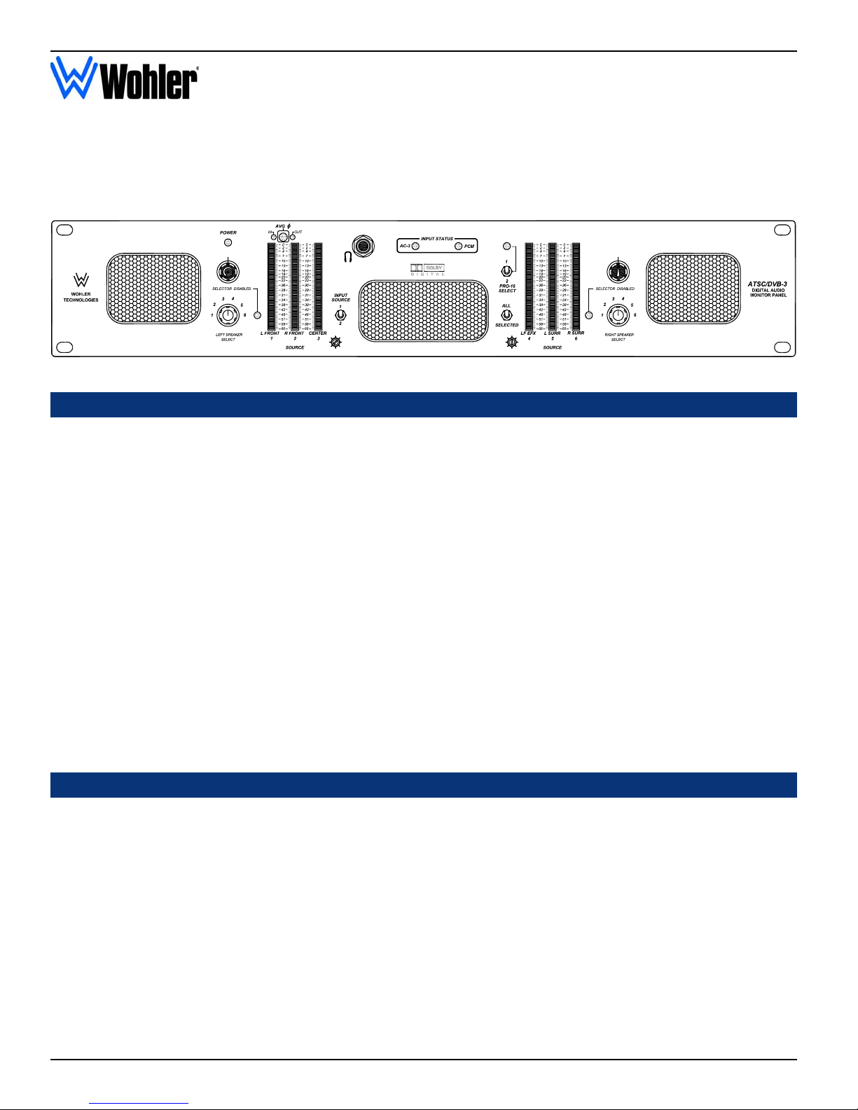
ATSC/DVB-3
Powered Digital Audio Monitor Unit
ATSC/DVB-3 Front Panel
Description
The ATSC/DVB-3 is a powered stereo monitor designed specifically for flexible, comprehensive monitoring of the six audio channels
associcated with ATSC/DVB programming. The unit is 2RU in size, for excellent fidelity without using excessive rackspace in the critical
"operating zone" of rack bays and consoles.
The ATSC/DVB-3 accepts AES/EBU and/or Dolby Digital® ( AC-3) input signals providing capabilities to handle monitoring requirements
throughout the facility.
The speakers and amplifiers are arranged in the popular Wohler “biamp summed bass stereo” configuration: bass frequencies from ALL
selected channels are summed into a 20W amplifier, which drives the woofer. The two side channel amplifiers and speakers reproduce, in
stereo, only the mid- and high- frequencies. Note that the center speaker (the woofer) is NOT a dedicated Center nor LFE speaker. There is
also a headphone output, which mutes the speakers while in use.
High-resolution, wide-range LED bargraph level meters are provided for all six channels for very accurate metering. 53 bicolor segments
spanning a range of 65 or 90 dB simultaneously display signal levels according to both the PPM and VU standards. An adjustable-duration
hold of the peak PPM value may also be displayed.
Both Left/Right and Front/Surround "Phase"/Polarity LED indications are provided to alert of possible cancellation from mixdown in any
likely home playback situation.
To isolate possible faults, rotary switches let the operator route any one or pair of inputs to left and right speaker channels for acoustic
monitoring. A toggle switch mixes all six channels down to two for listening to all channels at once.
Features
• 2U high: highest fidelity in minimum rackspace
• AES/EBU, or encoded ATSC/MPEG-2 (Dolby
Digital®) inputs on BNC and XLR connectors
• Simultaneous visual monitoring of all 6 channels
• Pro-16 signal select switch and indication LED
• Left/Right Front “phase" indicators
• Select any channel or pair of channels for isolated
listening, or a stereo mixdown of all 6 channels
• 53-segment tri-color, wide-range, high-resolution
LED bargraph level meters
• SDI and AES Status Indication LEDs
4
© 2005 Wohler Technologies Inc. ALL rights reserved
• Selected channel analog outputs on XLR connectors
• Headphone output
ATSC/DVB-3 User Manual P/N 821507 Rev-D Section 1: General Features, Specifications, and Installation
Applications
The ATSC/DVB-3 is ideally suited for use in VTR bays, mobile production vehicles, teleconferencing installations, multimedia
systems, satellite links and cable TV facilities, and on-air radio studios. Designed and manufactured in the U.S., the ATSC/DVB-3
is backed by a strong warranty and a satisfaction guaranteed return policy.
General Specifications
Input Meter Dynamics:
Input Level for Maximum
Output (Volume Full On):
Input Overload:
Peak Acoustic Output
(@ 2 ft.):
Response, Sixth Octave:
Power output,
ΩΩ
Ω):
ΩΩ
ΩΩ
Ω):
ΩΩ
RMS Each Side (4
RMS Bass (4
Distortion, Electrical:
Distortion, Acoustic:
Hum and Noise:
Magnetic shielding:
Input connectors:
Medium-size Segments
Medium-size Segments
(for Middle -distance Viewing
(for Middle -distance Viewing
Simultaneous VU (bar) and PPM (dot)
0 dBv balanced
+26 dBv balanced
104 dB SPL
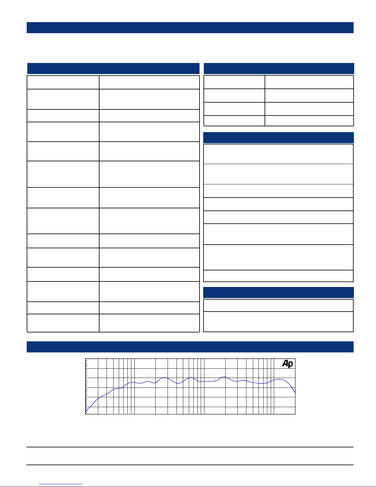
80 Hz - 16 kHz ± 5 dB)
(-10 dB @ 40 Hz, 20 kHZ)
14 W transient / 10 W continuous
35 W transient / 25 W continuous
Less than 0.15% at any level below
limit threshold
6% or less at worst case frequencies
above 120 Hz, including cabinet
resonance; typically less than 1.5%
Better than -68 dB below full output
Less than 0.8 Gauss any adjacent
surface
Balanced: XLR
ATSC/MPEG-3 Input Specifications
Input impedance:
Minimum input level:
Playback mode:
Input connector:
75Ω (ohm) unbalanced
250 mv
“Line”
BNC
AES/EBU Input Specifications
Input characteristics:
Minimum input level:
Conversion data width:
Dynamic range:
Frequency Response:
Analog Output
Distortion:
Analog outputs:
Meter input ‘0’ level:
BNC:75 Ω (ohm) unbalanced
XLR:110 Ω (ohm) balanced
.
5V p-p unbalanced,
2.2V p-p balanced
20 bit
95 dB
10 Hz - 20 kHz +/- 0.5 dB
< 0.005%
balanced, line-level
(-20 dbfs=+4 dBu); minimum
load impedance:10k Ω (ohm)
-20 dBfs
Power consumption
(Average Maximum):
AC Mains input:
"ALL" Channel Summing
Assignments*:
* On special order, custom combinations of selected channels are available; either in lieu of, or in addition to, the regular selections.
60 W
100-220VAC, 50-60 Hz
Left Side =LFront+LSurr+1/2Center+1/2LFE
Right Side =RFront+RSurr+1/2Center+1/2LFE
Weight:
Dimensions (HxWxD):
Physical Specifications
18 lbs. (8.2 kg)
3.5 x 19 x 12 inches
(89 x 483 x 298 mm)
Audio Response Curve
+10
0
d
-10
B
-20
-30
2k1k50020010050 20k20
Hz
Typical 1/6 Octave Audio Response Curve
5k
Units are designed to meet, at time of manufacture, all currently applicable product safety and EMC requirements, such as those of CE. 0 dbV
ref. 0.775V RMS. Features and specifications subject to improvement without notice.
10k
© 2005 Wohler Technologies Inc. ALL rights reserved
5

ATSC/DVB-3 User Manual P/N 821507 Rev-D
Section 1: General Features, Specifications, and Installation
Installation
Mounting
The unit should be mounted where convenient for operating persons, ideally at approximately ear level for best high frequency response. Its
superior magnetic shielding eliminates concerns about locating it adjacent to most types of CRT monitors, including even high-resolution
color monitors.
Heat Dissipation
Heat dissipated by the speaker amps is conducted directly to the left side of the chassis; no special considerations for cooling are necessary
as long as the ambient temperature inside the rack area does not exceed approximately 40°C (104°F).
Sympathetic Vibration
Sympathetic vibration from other equipment (cables, etc.,) in the rack may be serious enough to interfere with the unit’s sound quality out in
the listening area. The use of thin card stock and/or felt or foam weather-stripping type materials between adjacent vibrating surfaces, or tying
up loose cables, etc., may be required to stop vibrations external to the unit.
Mechanical Bracing
The chassis is securely attached to the front panel at eight points along its surface, not just at the four corners of the chassis ears. This feature
will reduce or eliminate rear bracing requirements in many mobile/portable applications. The weight of internal components is distributed
fairly evenly around the unit.
Audio Connections
Connection of the audio feeds is straightforward. Please refer to the system block diagram on page 18 for clarification of the general
signal paths into and out of the ATSC/DVB-3 unit.
Inputs are via either BNC or XLR connectors. BNC inputs are 75
avoid mis-matched cable types and other similar causes of undesired reflections in RF signal systems. If severe enough, such reflections
can result in corruption of the digital datastream.
ΩΩ
Ω unbalanced; XLRs are 110
ΩΩ
ΩΩ
Ω balanced. Care should be exercised to
ΩΩ
AC Power
The unit's AC mains connection is via a standard IEC inlet, with safety ground connected directly to the unit's chassis. The universal AC
input (100-240VAC, 50/60Hz) switching power supply is a self-resetting sealed type, with automatic over-voltage and over-current
shutdown. There is no user-replaceable fuse in either the primary or secondary circuit.
6
© 2005 Wohler Technologies Inc. ALL rights reserved
 Loading...