

Page 1

CONFIDENCE IS EVERYTHING.™
World Leader of In-Rack, Audio, Video, Data Monitoring, and Closed Captioning Solutions
AMP1A Series
•AMP1A-30 •AMP1A-106
• AMP1A-Plus • AMP1A-LP10S
1 RU, Analog Audio Monitors with Level
Meters
User Guide
Part Number 821020, Revision B
Page 2

© 2010 Wohler Technologies, Inc. and PANORAMA. All rights reserved.
This publication is protected by federal copyright law. No part of this publication may be
copied or distributed, stored in a retrieval system, or translated into any human or computer
language in any form or by any means electronic, mechanical, manual, magnetic, or otherwise,
or disclosed to third parties without the express written permission of Wohler Technologies.
Reproduction
Licensed users and authorized distributors of Wohler Technologies, Inc. products may copy
this document for use with Wohler Technologies., Inc. products provided that the copyright
notice above is included in all reproductions.
Customer Support
Wohler Technologies, Inc.
31055 Huntwood Avenue
Hayward, CA 94544
www.wohler.com
Phone: 510-870-0810
FAX: 510-870-0811
US Toll Free: 1-888-596-4537
(1-888-5-WOHLER)
Web: www.wohler.com
Sales: [email protected]
Support: [email protected]
Disclaimers
Even though Wohler Technologies, Inc. has tested its equipment and software, and reviewed
the documentation, Wohler Technologies, Inc. makes no warranty or representation, either
express or implied, with respect to software, documentation, their quality, performance,
merchantability, or fitness for a particular purpose.
Wohler Technologies, Inc. reserves the right to change or improve our products at any time and
without notice.
In no event will Wohler Technologies, Inc. be liable for direct, indirect, special, incidental, or
consequential damages resulting from any defect in the hardware, software, or its
documentation, even if advised of the possibility of such damages.
Some states do not allow the exclusion or limitation for incidental or consequential damages, so
the above exclusion or limitation may not apply to you.
Printing
This document is intended to be printed on a duplex printer, such that the copy appears on
both sides of each page. This ensures that all new chapters start on a right-facing page.
This document looks best when printed on a color printer since some images may be indistinct
when printed on a black and white printer.
Other Technologies and Products
Dolby, Dolby Digital, Dolby D, and Dolby E are registered trademark of Dolby Laboratories,
Inc.
Microsoft Windows, and Internet Explorer are registered trademarks of Microsoft Corporation.
Last Update
July 27, 2010
821020: AMP1A Series User Guide
ii
© 2010 Wohler Technologies, Inc. All rights reserved.
Page 3

AMP1A Series User Guide
Introduction
Overview
The AMP1A Series of audio monitors provides self-powered, fullfidelity stereo monitoring in the smallest rack space possible.
Topics
Topics Page
Introduction 1
Safety Instructions 2
Installation Recommendations 3
Description 4
Application 4
Features 5
Specifications 5
Audio Amplifier and Speaker Configuration 7
Optional Features 8
Front Panel Controls 9
Rear Panel Connectors 13
Internal Switch Settings 17
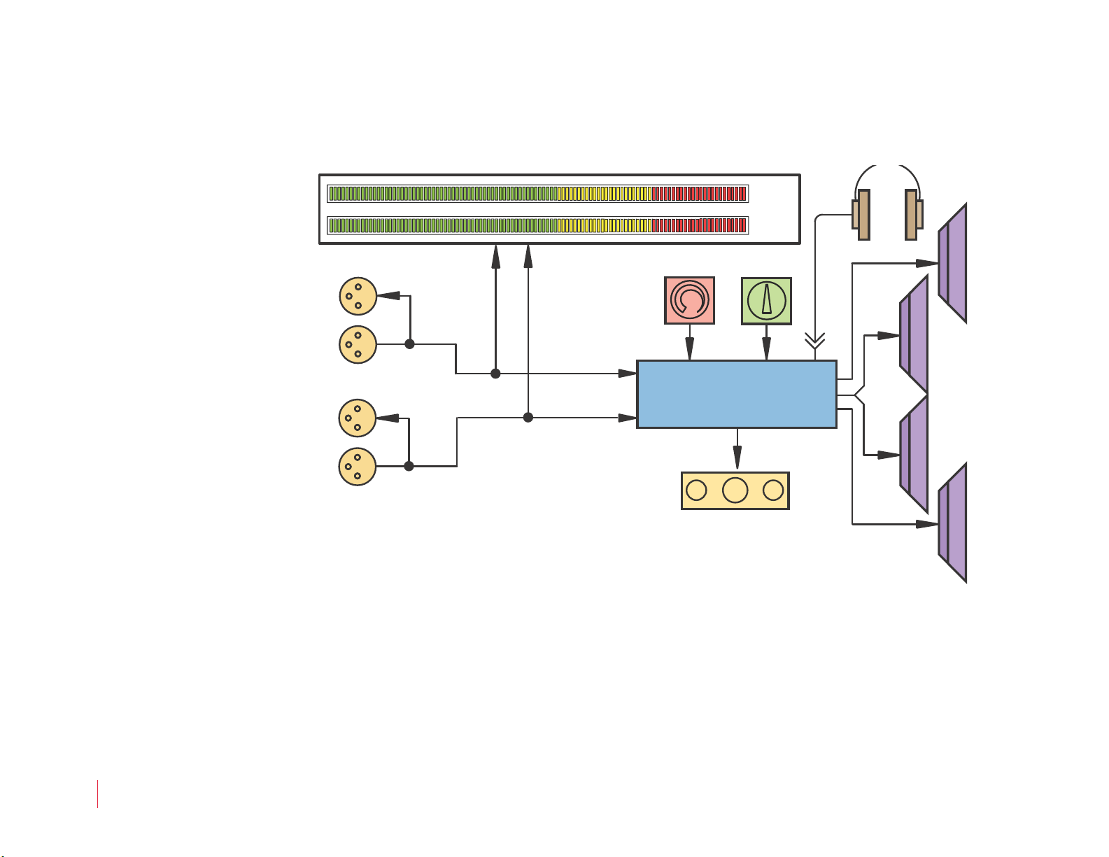
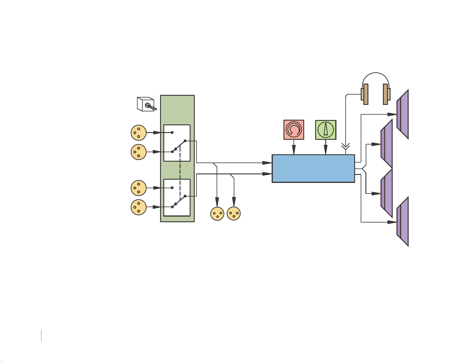
Technical Functional Overview 22
821020: AMP1A Series User Guide
© 2010 Wohler Technologies, Inc. All rights reserved.
1
Page 4

AMP1A Series User Guide
Safety Instructions
Safety Instructions
1. Read, keep, and follow all of these instructions; heed all warnings.
2. Do not use this equipment near water.
3. Use only a dry cloth to clean the equipment.
4. Do not block any ventilation openings. Install only in accordance
with the instructions in the section entitled, “Installation
Recommendations” on page 3.
5. Do not install near any heat source such as a radiator, heat register,
amplifier, or stove.
6. Do not expose the equipment to rain or moisture.
7. Do not attempt to plug the unit into a two-blade outlet (with only
two prongs of equal width).
IMPORTANT:
By design, these monitors will only plug into a three-prong outlet for
your safety. If the plug does not fit into your outlet, contact an
electrician to replace the obsolete outlet.
8. Protect the power cord from being walked on or pinched,
particularly at plug’s source on the equipment and at the socket.
9. Use only the attachments/accessories specified by the
manufacturer.
10. Unplug the equipment during lightning storms or when unused
for long periods of time.
11. Refer all servicing to qualified service personnel. Servicing will be
required under all of the following conditions:
• The equipment has been damaged in any way, such as when
the power-supply cord or plug is damaged.
• Liquid had been spilled or objects have fallen onto the
equipment.
• The equipment has been exposed to rain or moisture.
• The equipment does not operate normally.
• The equipment has been dropped.
821020: AMP1A Series User Guide
2
© 2010 Wohler Technologies, Inc. All rights reserved.
Page 5

AMP1A Series User Guide
Installation Recommendations
Installation Recommendations
Unpacking
Unpack the AMP1A Series monitor from the shipping container and
inspect all components for shipping damage. If you find any damage,
notify the shipping carrier for claims adjustments.
Compare the shipping box contents to the packing slip. Contact
Wohler’s customer support personnel about any discrepancies.
(Wohler’s contact information in on the copyright page ii, of this
manual).
Heat Dissipation
The ambient temperature inside the mounting enclosure should not
exceed 40° Celsius (104° Fahrenheit). Adjacent devices can be rack
mounted (or stacked) in proximity to the unit if the above temperature
is not exceeded. Allow a 1RU (1.75”/44.45mm) space above and below
the unit for air circulation.
Important:
The heat generated by the power amplifiers, power supplies, and other
components is vented by slots in the side of the unit. Therefore, as a
safety precaution, we advise you to be sure to allow proper ventilation
on both sides of the unit.
Rack Mounting
You should install the monitor into a standard 19" rack and requires a
maximum of 3RU of rack space (the 2RU unit, plus 1RU above and
below). Also, install it as close to the operator’s direct viewing angle as
possible as LCD screens can appear to display anomalies outside this
viewing angle.
Cable Connections
Wohler recommends Beldon 8281 or Belden 1694A cables for analog
video signals and Beldon 9451 cables for analog audio signals.
821020: AMP1A Series User Guide
© 2010 Wohler Technologies, Inc. All rights reserved.
3
Page 6

AMP1A Series User Guide
Description
Power
Each unit comes with a standard 24VDC/3.0A internal power supply
and connects an A/C mains power source (65W, 100 to 240 VAC, 50/
60Hz) to the IEC connector provided on the rear panel of the unit.
Electrostatic Discharge (ESD)
As with most electronic equipment, static discharges can damage
components within the unit. Take precautions to ensure your
installation environment is not subject to ESD.
Description
All models in the AMP1A series contain four high performance
transducers driven by three power amplifiers: two amplifier/driver
combinations handle midrange and high frequency information in
stereo, while the third center channel reproduces information below the
500 Hz crossover point through dual woofers.
All AMP-1A analog audio models come equipped with stereo volume
and balance potentiometers, a power indication LED, and a headphone
output. Output limiter circuits are incorporated to protect the speakers,
and extensive magnetic shielding allows placement immediately
adjacent to video monitors with no color impurities.
Application
The AMP1A Series is ideally suited for use in VTR bays, mobile
production vehicles, teleconferencing installations, multimedia
systems, satellite links and cable TV facilities, and on-air radio studios.
Designed and manufactured in the U.S., the AMP1A is backed by a
strong warranty and a satisfaction guaranteed return policy.
821020: AMP1A Series User Guide
4
© 2010 Wohler Technologies, Inc. All rights reserved.
Page 7
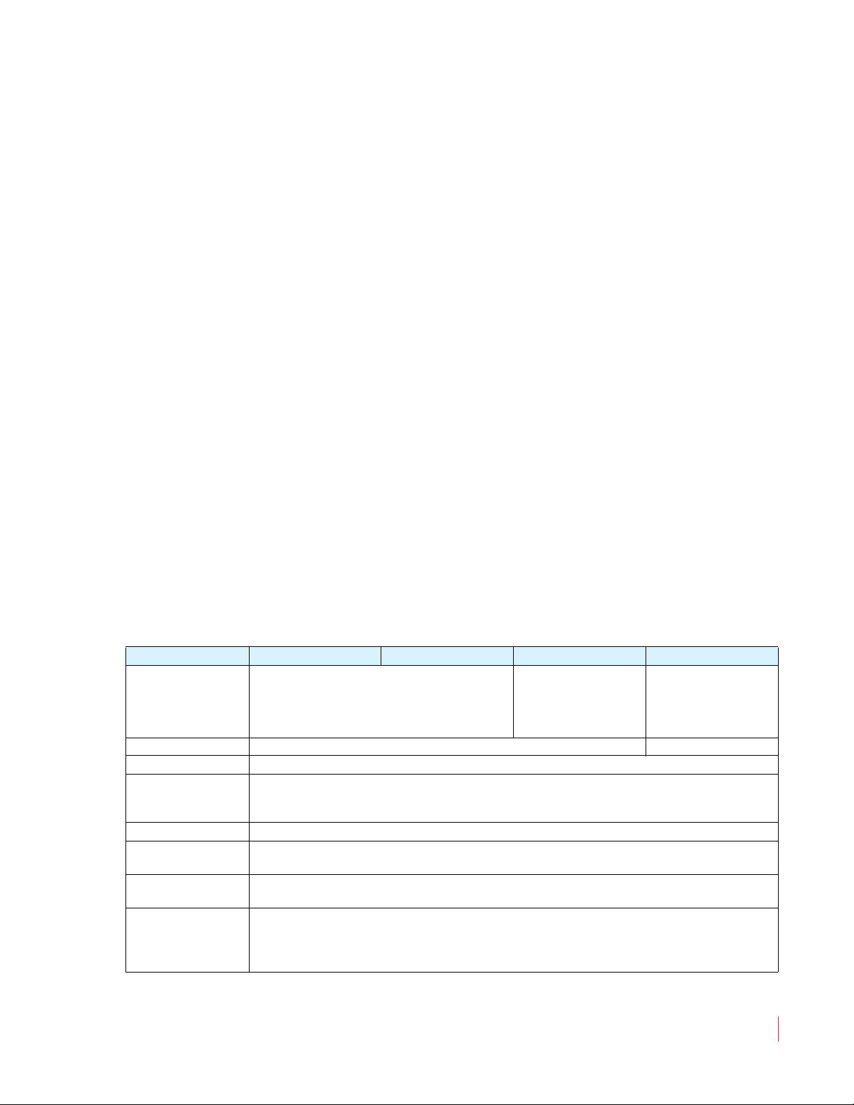
Features
• 98 dB SPL at two feet
• Only one rack space high
• Excellent high frequency response for positive detection of
• Audible indication of phase/polarity problems
• Thorough magnetic shielding for placement next to video monitors
• Numerous control and input options
• Quick and easy installation: simply slide in the rack and connect
AMP1A Series User Guide
Features
background whine and noise
audio and AC power
Specifications
The AMP1A Series monitors meet the following specifications.
Table 1–1 AMP1A Series Monitors Specifications
Specification AMP1A-30 AMP1A-106 AMP1A-LP10S AMP1A Plus
4 Balanced Analog
Inputs
Outputs 2 Analog Audio on XLR (Left & Right)
Input Impedance > 40k balanced
Input Level for
Maximum Output
(Volume Full On)
Input Overload +26 dBv balanced
Peak Acoustic
Output (at 2 ft.)
Response, 6th
Octave
Power Output
RMS Each Side
RMS Base
2 Balanced Analog Audio on XLR
(Left & Right)
0 dB balanced
80 Hz to 16 kHz ± 7 dB (-10 dB @ 50 Hz to 22 kHz)
10 W transient / 5 W continuous
20 W transient / 10 W continuous
2 Banks of 10 Phoenix
(Left & Right)
98 dB SPL
Audio on XLR
(Left & Right)
2 Unbalanced RCA
821020: AMP1A Series User Guide
© 2010 Wohler Technologies, Inc. All rights reserved.
5
Page 8
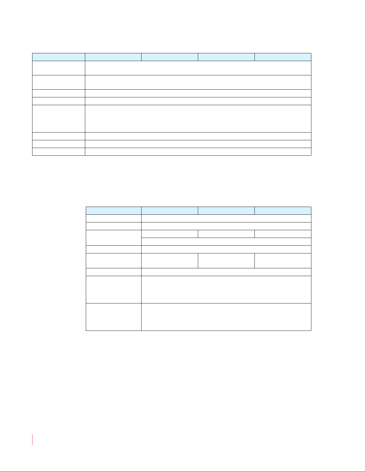
AMP1A Series User Guide
Specifications
Table 1–1 AMP1A Series Monitors Specifications
Specification AMP1A-30 AMP1A-106 AMP1A-LP10S AMP1A Plus
Distortion,
Electrical
Distortion,
Acoustic
Hum and Noise Better than -68 dB below full output
Magnetic Shielding <1 Gauss any adjacent surface
Power
Consumption
(Average
Maximum)
AC Mains Input 100 to 240 V AC, 50 to 60 Hz
Dimensions 1.75 “ H x 19” W x 12” D (44.5 mm H x 483 mm W x 298 mm D)
Weight 14 lbs. (6.4 kg)
8% or less at worst case frequencies above 180 kHz including cabinet resonance; typically <2%
< 0.15% at any level below limit threshold
35 W
Table 1–2 below lists the specifications for the level meters for all of the
monitors in the AMP1A Series except for the AMP1A Plus which does
not include level meters.
Table 1–2 Level Meters Specifications
Specification AMP1A-30 AMP1A-106 AMP1A-LP10S
Level Calibration -6, 0, +4, +8 dBv
Frequency Response 20 Hz to 18 kHz (± 0.5 dB)
Level Meter Type
LED Color Tri-Color: Red, Green, and Amber
Metering Range
Display Modes VU or PPM, Selectable
VU Characteristics
Rise Time
Fall Time
PPM Characteristics
Attack Time
Decay Time
30-Segment, 106-Segment 10-Segment
Two Tri-Color LED Bar Graph
65 dB
(+16 dB to -49 dB)
300 ms to 99% of full indication
2 seconds, 0 to -20 dB
72 dB
(+16 to -56 dB)
300 ms
10 ms
23 dB
(+3 to -20 dB)
821020: AMP1A Series User Guide
6
© 2010 Wohler Technologies, Inc. All rights reserved.
Page 9

AMP1A Series User Guide
Audio Amplifier and Speaker Configuration
Audio Amplifier and Speaker
Configuration
Audio Amplifiers
All AMP1 Series models contain high performance speakers driven by
three power amplifiers; two amplifier/driver combinations handle
midrange and high frequency information in the left and right (stereo)
speaker channels, while the third amplifier channel sums the left and
right channel information below the 500 Hz crossover point in the
woofer (bass) speaker(s). Note that the woofer channel is not a
dedicated LFE or center channel.
Speaker Configuration
The 1U rack size AMP1 Series products are configured with two
speakers (left and right) to reproduce mid- and high-range audio
frequencies (in stereo), but feature two woofer speakers to reproduce
the summed (combined) low-range audio frequencies from the left and
right speaker input channels. It should be noted that both woofer
speakers, which are wired in series, are driven from one woofer
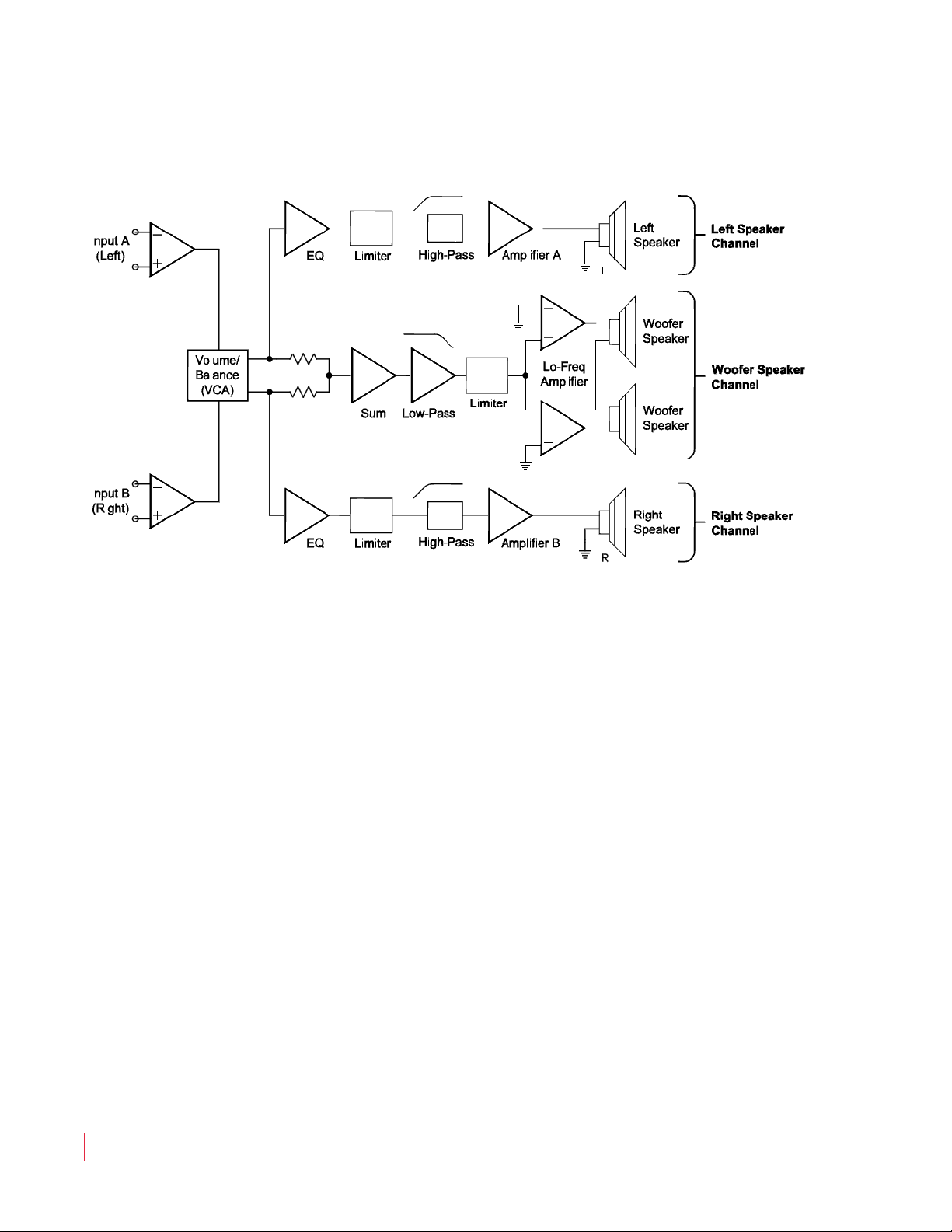
speaker channel, and are not stereo. See the simplified diagram below
for a block diagram of the AMP1 Series audio amplifier/speaker
configuration.
821020: AMP1A Series User Guide
© 2010 Wohler Technologies, Inc. All rights reserved.
7
Page 10
AMP1A Series User Guide
Optional Features
Figure 1–1 Audio Amplifier and Speaker
Configuration
Optional Features
Wohler Technologies, Inc. offers by far the broadest range of standard
production audio monitors. Standard-production AMP1A Series
monitors or special orders can include the following functions (and
combinations thereof):
• Separate channel volume controls (SVC Option)
• Alternate level meter scales and color maps
• Bar graph display phase correlation (F Option)
• Multiple input and output connector type choices
For other custom orders, contact your Wohler Sales representative.
(Wohler’s contact information is on the copyright page of this
document.)
821020: AMP1A Series User Guide
8
© 2010 Wohler Technologies, Inc. All rights reserved.
Page 11

Front Panel Controls
Common Controls
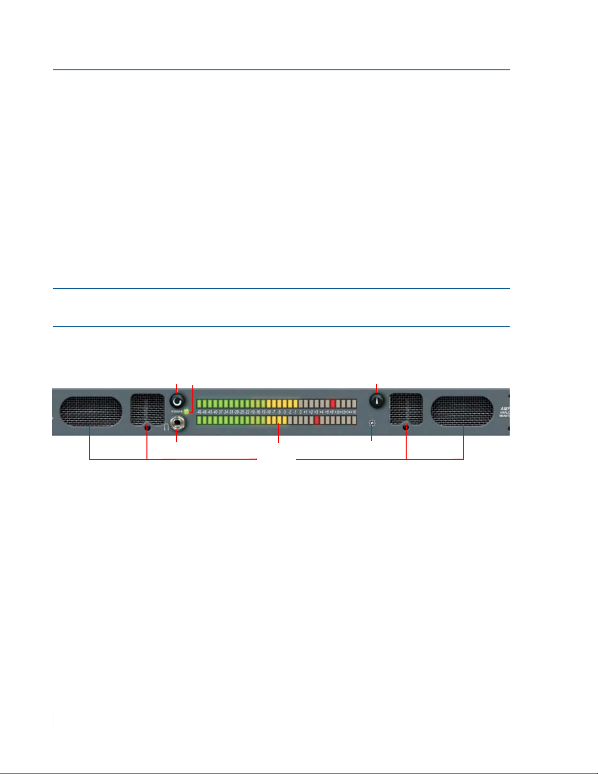
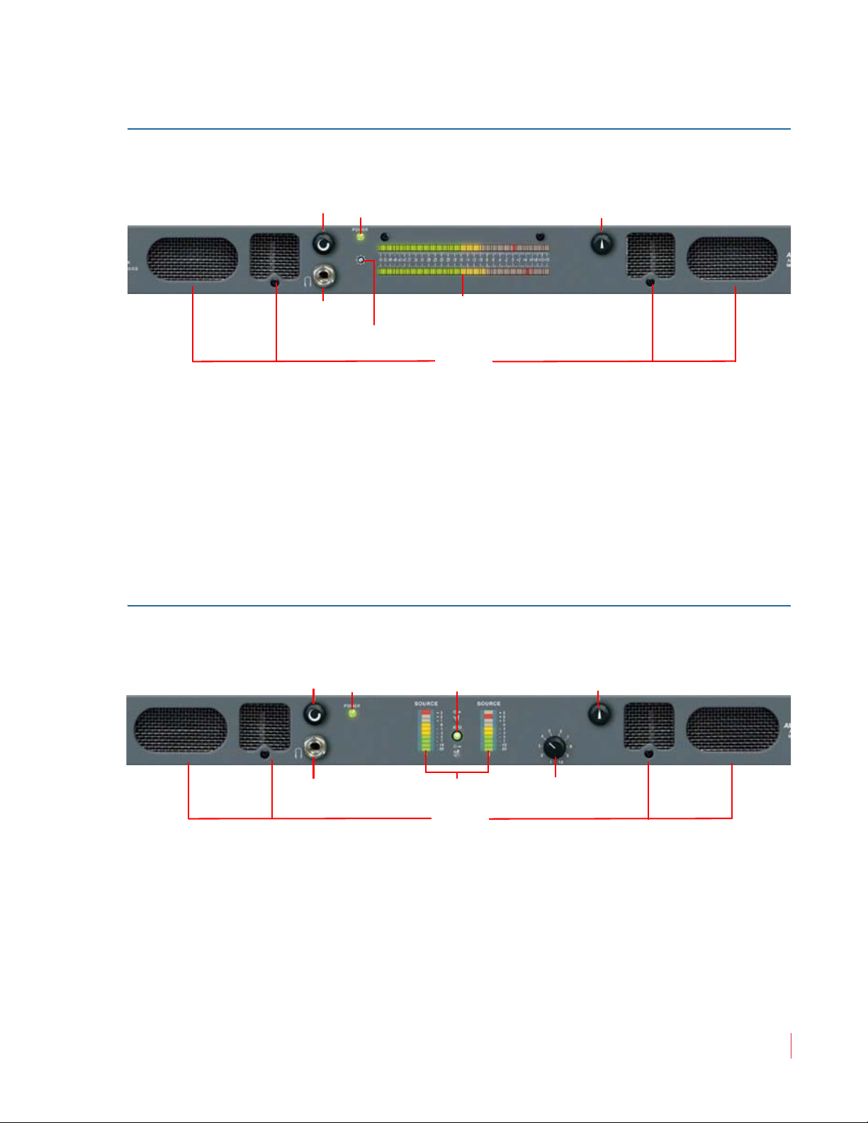
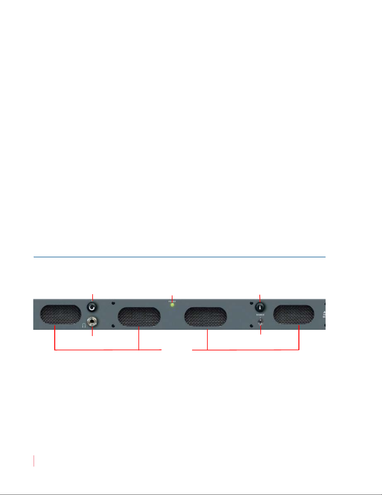
• Speakers: The AMP1A internal speaker system is comprised of two
mid-range tweeter speakers (left and right) and two woofer
speakers (left and right). The two mid-range speakers reproduce, in
stereo, only the mid and high frequencies, while the two woofer
speakers monaurally reproduce the low frequencies.
• Volume Control: This controls the loudness of the audio
reproduced by the internal speakers or connected headphone.
Clock-wise rotation of this control increases the loudness of the
monitored audio.
• Headphones: The headphone output monitors the same audio
signals as monitored through the internal speakers. However, when
you plug in headphones, the internal speakers will mute. This jack
accepts a standard 1/4” phone type stereo plug.
AMP1A Series User Guide
Front Panel Controls
• Power LED: This LED glows green to indicate the monitor is
connected to operational mains power.
• Audio Level Meters: Audio levels are visually displayed via thigh-
resolution tri-color (red, amber, green) LED bar graph display level
meters. The upper level meter monitors Channel A (left) while the
lower level meter monitors Channel B (right). These bar graph
displays feature an auto-calibration feature and are user adjustable
for display mode and reference level via a rear panel DIP module.
Peak hold, PPM ballistics, and alternative scales can be set through
an internal DIP switch.
• Balance Control: This pans the volume balance between the left and
right speakers. The balance control attenuates the signal from the
source, so that the left and right bass frequencies (summed together
and reproduced in the woofer channel) will also respond to the
balance control.
821020: AMP1A Series User Guide
© 2010 Wohler Technologies, Inc. All rights reserved.
9
Page 12
AMP1A Series User Guide
Speakers
Headphones
Level Meter Brightness
Level Meters
Volume
Balance
Power
Front Panel Controls
Example If an audio signal of a voice speaking English is fed to the "A" (left)
input and a voice speaking Spanish is fed to the "B" (right) input, then
the left speaker channel will reproduce the mid-range and high-range
frequencies of the English speaking voice, the right speaker channel
will reproduce the mid-range and high-range frequencies of the
Spanish speaking voice, and the woofer speaker channel will
reproduce the summed (combined) low-range frequencies of both
voices.
If the balance control is panned to the left, then the Spanish speaking voice in
the right speaker channel will diminish in volume, the Spanish speaking
voice in the woofer speaker channel will also diminish, and the English
speaking voice in both the right speaker channel and woofer speaker
channel will increase slightly (to maintain overall output level). The
converse is true if the balance control is panned to the right.
AMP1A-30-Specific Front Panel Controls
Figure 1–2 AMP1A-30 Front Panel
• Level Meters: The AMP1A-30 features two, 30-segment, bar graph
audio meters.
• Level Meter Brightness (Recessed Rotary Switch): This control is
recessed into the front panel and can be accessed using a small
flathead screwdriver. Turning it clockwise will increase the relative
brightness of the bar graph LED segments. Adjusting this one
control will simultaneously affect the brightness of both bar graph
displays.
10
821020: AMP1A Series User Guide
© 2010 Wohler Technologies, Inc. All rights reserved.
Page 13
AMP1A Series User Guide
Speakers
Headphones
Level Meters
Volume
Balance
Power
Level Meter Brightness
Speakers
Headphones
Level Meters
Volume
Balance
Power
Phase
Source Select
Front Panel Controls
AMP1A-106-Specific Front Panel Controls
Figure 1–3 AMP1A-106 Front Panel
• Level Meters: The AMP1A-106 features two, 30-segment, bar graph
audio meters.
• Level Meter Brightness: This control is recessed into the front
panel and can be accessed using a small flathead screwdriver.
Turning it clockwise will increase the relative brightness of the bar
graph LED segments. Adjusting this one control will
simultaneously affect the brightness of both bar graph displays.
AMP1A-LP10S-Specific Front Panel Controls
Figure 1–4 AMP1A-LP10S Front Panel
• Level Meters: The AMP1A-LP10S features two, 10-segment, bar
graph audio meters.
• Source Select (10-Position Rotary Switch): This switch selects, from
the multi-channel inputs, a single stereo audio source (2 channels)
for monitoring through the unit.
821020: AMP1A Series User Guide
© 2010 Wohler Technologies, Inc. All rights reserved.
11
Page 14
AMP1A Series User Guide
Speakers
Headphones
Volume
Balance
Power
Source Select
Front Panel Controls
• Phase (LEDs): These three LEDs indicate the instantaneous and
average phase (polarity) conditions between the sources) assigned
to the left speaker channel and the source(s) assigned to the right
speaker channel. The larger LED labeled AVG indicates the average
phase condition between the left and right speaker channels. The
two smaller LEDs labeled Φ+ and Φ- indicate the instantaneous
phase relationships. Indication is as follows:
• The upper Φ+ LED glows (or blinks) green for in-phase
signals.
• The lower Φ- LED glows (or blinks) amber for out-of-phase
signals.
• The large center
AVG LED indicates the average phase
condition by glowing green for in-phase signals, or red for
out-of-phase signals.
In general, observing the average LED alone is sufficient for proper
phase monitoring. While it is normal for stereo signals to contain
some intermittent instantaneous out-of-phase and in-phase
conditions (Φ+ and Φ- LEDs), a steady red glow of the average LED
indicates an out-of-phase alarm condition.
AMP1A Plus-Specific Front Panel Controls
Figure 1–5 AMP1A Plus Front Panel
12
Source Select (Toggle Switch): This switch selects either the Source 1
Source 2 inputs for monitoring.
or
821020: AMP1A Series User Guide
© 2010 Wohler Technologies, Inc. All rights reserved.
Page 15
Rear Panel Connectors
Common Connectors
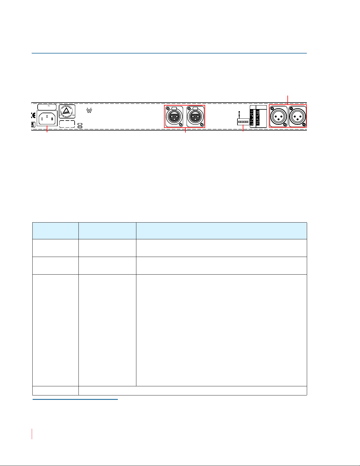
• Power (IEC-320): Attach the included power cord between this
connector and mains power (100 to 250VAC, 50 to 60 Hz). The front
panel Power LED will glow green to indicate operating voltages
are present.
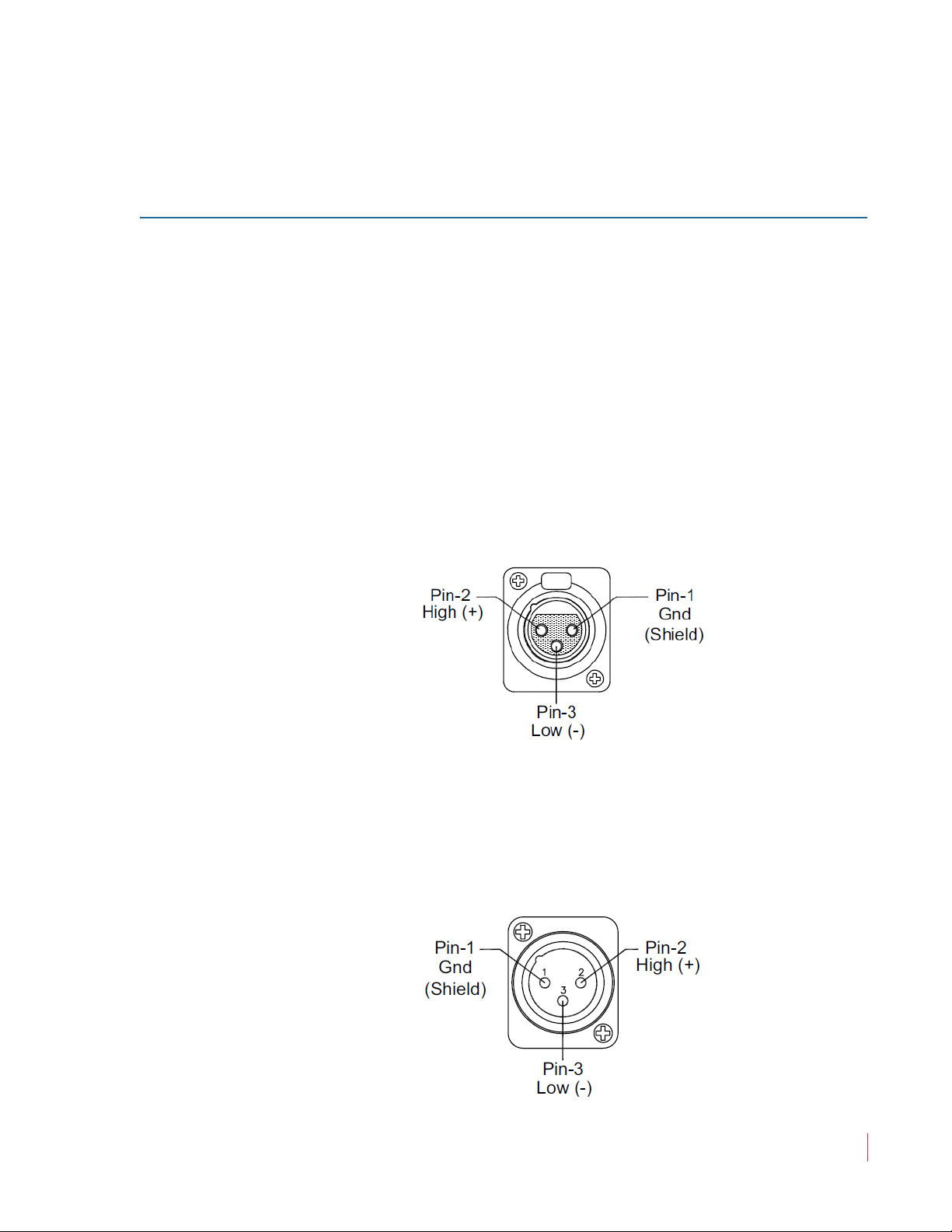
• Balanced Analog Audio Input (on XLR-F): These two 3-pin female
XLR connectors (left and right) accept standard analog audio signals
and are configured for 50K Ω balanced connections. Pinout
information for the XLR connectors is shown at bottom of this page.
AMP1A Series User Guide
Rear Panel Connectors
Note:
Figure 1–6 XLR-F Pin-Out
• Selected or Loop-Through Analog Audio Output (XLR-M): These
two 3-pin male XLR connectors output balanced low impedance
analog signals. Pinout information for connectors is shown Figure
1–7 below.
Figure 1–7 XLR-M Pin-Out
The AMP1A-LP10S does not include this feature and
the AMP1A Plus has two pair of these connectors.
821020: AMP1A Series User Guide
© 2010 Wohler Technologies, Inc. All rights reserved.
13
Page 16
AMP1A Series User Guide
YEAR
50/60 Hz 1.0 A
100-240 VAC
SERIAL NO.
MONTH
www.Wohler.com
Fax
Tel
Technologies
Wohler
+1-510-870-0811
+1-510-870-0810
253840
XLR LOOP-THRU
CH A(L) CH B(R)
6
5
4
3
12
0 PPM/PPM
54
32
+6
+4
PPM
VU/PPM
+8
METER
CALIB
DISPLAY
MODE
VU/VU
CALIBRATE
OPERATE
CH A(L)
3
21
3
1
2
Operation/Calibration
Mode Select
Analog Audio In
(Left & Right)
Power
Analog Audio Loop-Through
(Left & Right
Rear Panel Connectors
AMP1A-30 and AMP1-106 Rear Panel Connectors
Figure 1–8 AMP1A-30 and AMP1-106 Rear Panel
Connector Descriptions
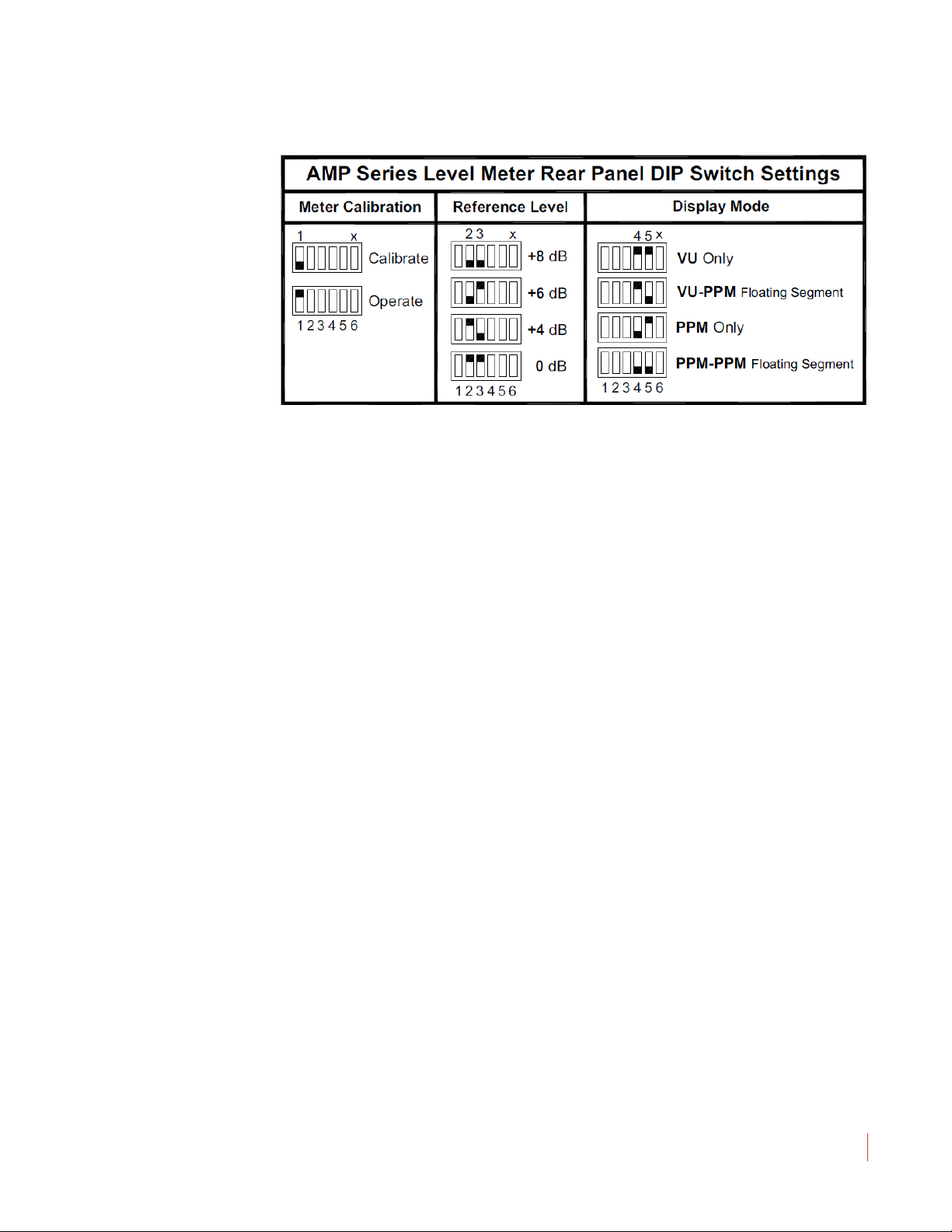
Operation/Calibration Mode Select (Six-Position DIP Switch): This
switch sets the Line Level Calibration, Reference Level, and PPM/VU
Display Mode. See Table 1–3 below and Figure 1–9 on page 15 for
details.
Table 1–3 Operation/Calibration Mode Select Switch Settings
Switch
Numbers
a
1
2 and 3 Reference Level
Function Description
Operation/
Calibration
Determines whether the monitor is in a normal
operational mode or a calibration cycle.
Adjusts the level of the input signal and the resultant level
displayed on the LED bar graphs. Factory setting is +4 dB.
Determines how peak levels are displayed for the
associated meters on the front panel. The four
settings include:
• VU Only,
• VU-PPM Floating Segment,
4 and 5 Display Mode
• PPM Only, and
• PPM-PPM Floating Segment.
The VU Only selection has a VU floating segment
when a peak hold value is selected using the internal
10-position DIP switch module. The factory default
setting is VU-PPM floating segment.
6Not Used
14
a The switch numbers in the DIP switch module are numbered from left to right.
821020: AMP1A Series User Guide
© 2010 Wohler Technologies, Inc. All rights reserved.
Page 17
AMP1A Series User Guide
Rear Panel Connectors
Figure 1–9 DIP Switch Settings
Note:
Switch position 6 is not used.
Calibration Instructions
1. Turn on the power.
2. Apply the desired reference level (nominal 0) signal to all
channels.
3. Make sure the reference level DIP sections (2 and 3) are set to the
nearest level of the input signal being applied for calibration (i.e.,
0, +4, +6 or +8). Verify that the signal applied to all four channels is
within ± 4 dB of the reference level set in DIP switches 2 and 3.
4. Place DIP Switch 1 in the down position (calibration).
5. Wait 10 seconds for the unit to update its calibration to your
settings.
6. Place DIP Switch 1 in the up position (operation) and return unit to
service.
Note:
You can only auto-calibrate the monitor once for each
power cycle. Once you have put DIP Switch 1 in the
calibration position, you must cycle the power before
that DIP switch will be functional again, even if a
calibration attempt was unsuccessful.
If you want to re-calibrate, turn off the power to the unit
and repeat steps 1 through 6.
821020: AMP1A Series User Guide
© 2010 Wohler Technologies, Inc. All rights reserved.
15
Page 18
AMP1A Series User Guide
Power
Selected Analog
Out (Left & Right
Analog Audio Inputs
(Left & Right)
231 132
CH B (R)
XLR LOOP-THRU
CH A (L)
SOURCE 1 CH B(R)
SOURCE 2 CH B(R)
SOURCE 1 CH A(L)
SOURCE 2 CH A(L)
Wohler
Technologies
+1-510-870-0810
+1-510-870-0811
www.Wohler.com
Fax
Tel
S
253884-01
AMP1A-2S
100-240 VAC
50/60 Hz 1.0 A
SERIAL NO.
MONTH
YEAR
MADE IN U.S.A.
Analog Audio In with Loop-
Through (Left & Right)
Power
Selected Analog
(Left & Right
Rear Panel Connectors
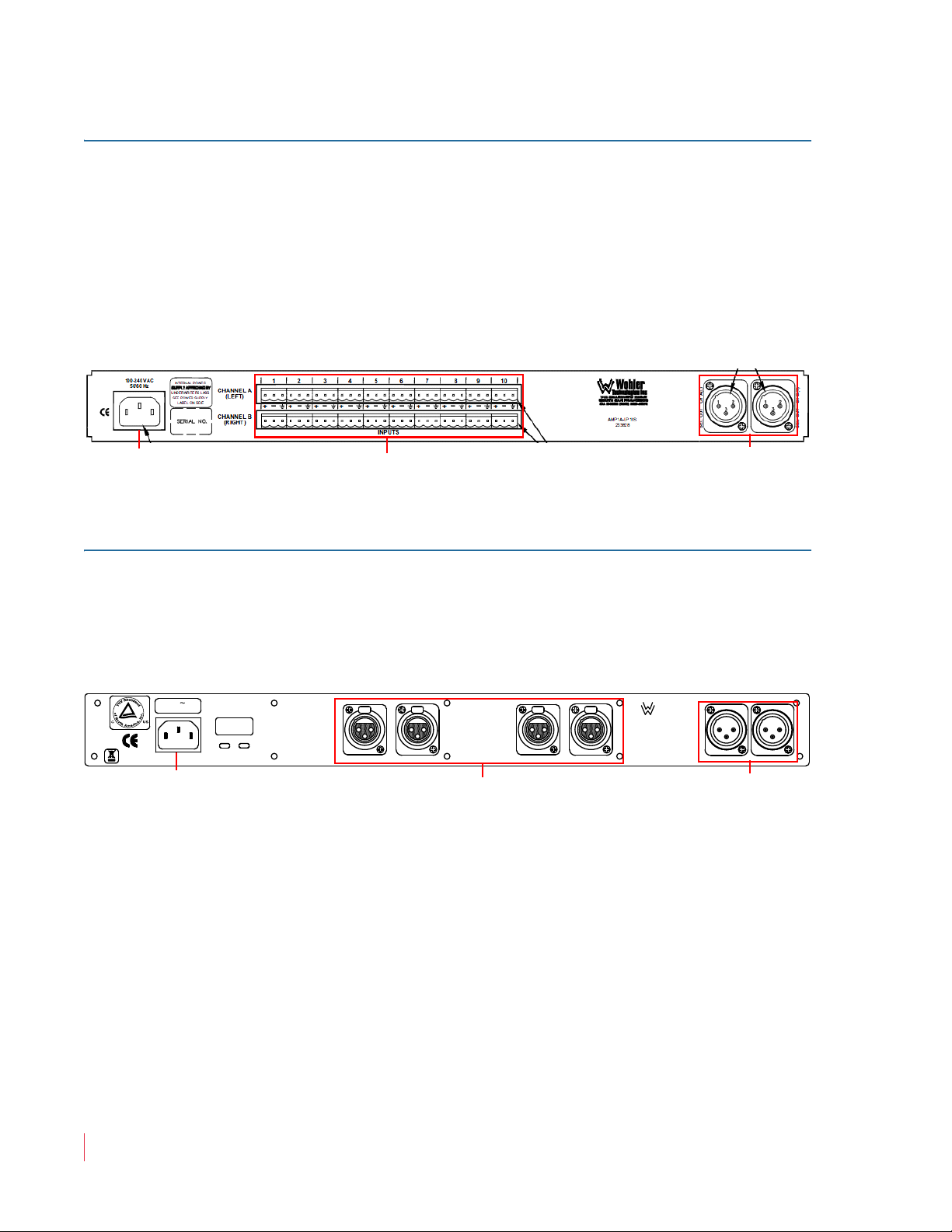
AMP1A-LP10S-Specific Rear Panel Connectors
Balanced Inputs (Channels 1-10, Left and Right, 3-Pin Male
Phoenix): These balanced (90K Ω) 3-pin Phoenix connectors accept
standard analog audio signals. The two banks of inputs, Channel A
(Left) and Channel B (Right), are comprised of ten connectors each for a
total of twenty inputs (ten stereo pairs). Connector pinout information
is silk-screened on the rear panel between the two rows of connectors.
Figure 1–10 AMP1A-LP10S Rear Panel
AMP1A Plus-Specific Rear Panel Connectors
The AMP1A Plus provides two analog audio inputs, Channel A (left)
and Channel B (right).
Figure 1–11 AMP1A Plus Rear Panel
16
821020: AMP1A Series User Guide
© 2010 Wohler Technologies, Inc. All rights reserved.
Page 19
AMP1A Series User Guide
Internal Switch Settings
Internal Switch Settings
After removing the top cover, you can access DIP switches that control
level meter settings and/or calibration settings.
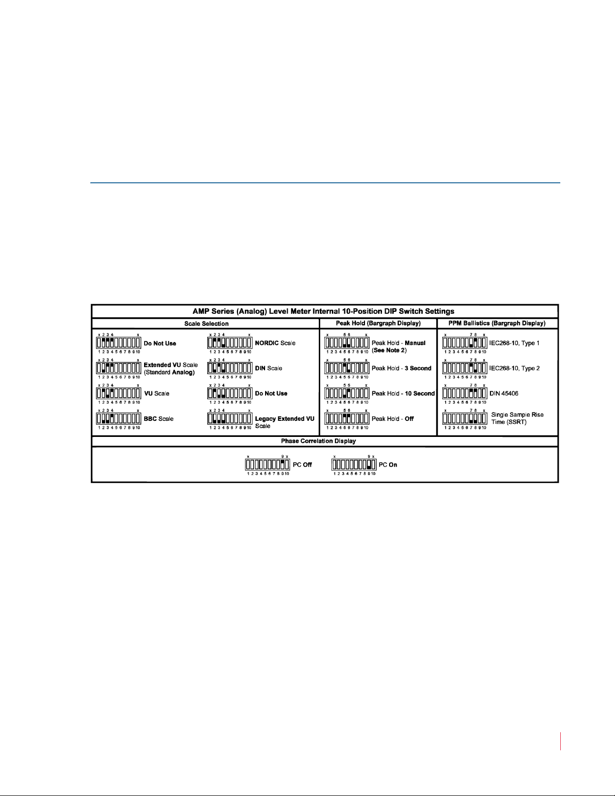
AMP1A-30 and AMP1-106 Internal Switch Settings
This 10-position DIP module is located on the 919174 PCB. Refer to
Figure 1–12 below for a complete list of settings and functions. (Switch
positions 1 and 10 are not used and should be left at the factory set
position.)
Figure 1–12 0-Position DIP Switch Settings
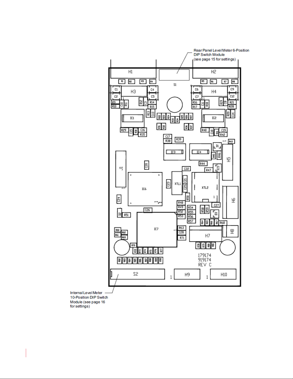
Figure 1–13 on page 18 illustrates the DIP switch location on the PCB.
821020: AMP1A Series User Guide
© 2010 Wohler Technologies, Inc. All rights reserved.
17
Page 20
AMP1A Series User Guide
Internal Switch Settings
Figure 1–13 Internal DIP Switch Location
18
821020: AMP1A Series User Guide
© 2010 Wohler Technologies, Inc. All rights reserved.
Page 21
AMP1A Series User Guide
Internal Switch Settings
Scale Selection
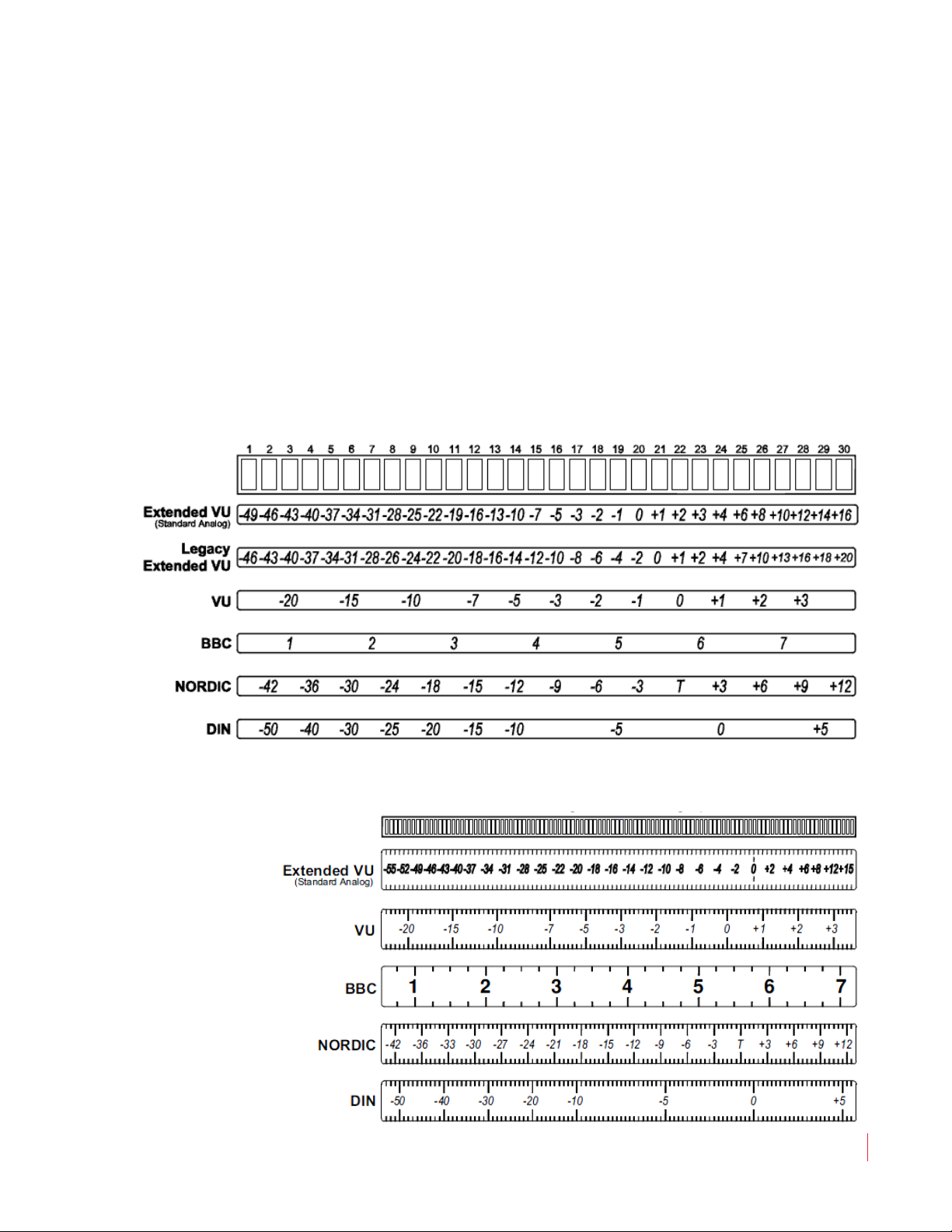
The standard scale used on the 30-segment bar graph display for the
AMP1A-30 is the Extended VU scale. However, if alternative scale
characteristics are selected for the level meters by setting the Alternate
Scale DIP switches (Figure 1–12 on page 17), it is recommended that a
label with the appropriate scale be applied to the front panel LED bar
graph level meters. Alternate scales include the VU, BBC, Nordic, and
DIN scales. The Extended VU scale is the standard scale for all AMP1A
Series models. See Figure 1–14 below for 30-segment alternate scales.
Contact Wohler Technologies for more information about Alternate
Scale labels.
Figure 1–14 30-Segment Scale Selection Options
Figure 1–15 106-Segment Scale Selection Options
821020: AMP1A Series User Guide
© 2010 Wohler Technologies, Inc. All rights reserved.
19
Page 22

AMP1A Series User Guide
Internal Switch Settings
Peak Hold
The Peak Hold - Manual setting allows the bar graph display meters to
indefinitely maintain the peak hold value until you reset it, either by
pressing a reset button (a special option specified at time of order) or by
removing power and then reapplying power to the unit (unplug/
replug power cord). Contact Wohler Technologies for more
information about this feature.
PPM Characteristics
The PPM characteristics determine the integration time (rise time) and
return time (fall time) of the level meter. The integration time is the
time it takes for the lighted segments of the level meter, after
application of a 5 kHz tone at a certain reference level, to rise within a
specified number of dB of that level. Return time is the time it takes for
the lighted segments of the level meter to fall a certain number of dB
after removal of a 5 kHZ tone of a certain reference level. The PPM
characteristics available for selection using DIP switch sections 7 and 8
of the 10-position Internal DIP Switch (Figure 1–12 on page 17) are
listed in Table 1–4 below.
20
Table 1–4 PPM Ballistics and Integration/Return
Time Relationships
PPM Ballistics Integration/Return Times
IEC268-10, Type 1
IEC268-10, Type 2
DIN 4506
Single Sample
Integration (Rise) Time is 5 ms (-2 dB);
Return (Fall) Time is 1.7 seconds (20 dB)
Integration (Rise) Time is 10 ms (-2 dB);
Return (Fall) Time is 2.8 seconds (24 dB)
Integration (Rise) Time is 5 ms (-2 dB);
Return (Fall) Time is 1.5 seconds (20 dB)
Integration (Rise) Time is a single sample;
Return (Fall) Time is 1.5 seconds (20 dB)
Phase Correlation Display
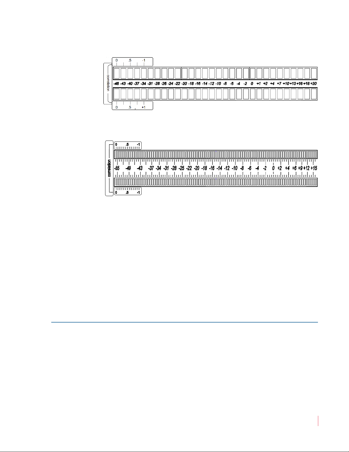
Since it is sometimes helpful to observe phase relationships between
two signals being monitored, you can enable the phase correlation
feature within the lower section of the existing bar graph pair in the
AMP1A-30. This feature is enabled by setting a switch on the internal
10-position DIP switch module located internally on the PCB. See
Figure 1–13 on page 18 for DIP module location, and Figure 1–12 on
page 17 for settings. The labels for this feature (see diagram below) can
be specified at the time of order or requested from Wohler for
application to existing units.
821020: AMP1A Series User Guide
© 2010 Wohler Technologies, Inc. All rights reserved.
Page 23
AMP1A Series User Guide
Internal Switch Settings
Figure 1–16 AMP1-30 Phase Correlation Labels
Figure 1–17 AMP1A-106 Phase Correlation Labels
Positive amounts of correlation are indicated by an ascending amber
bar in the lower (right channel) bar graph; negative correlation is
shown when a red bar ascends in the top (left channel) bar graph.
While the audio level in both channels is high enough, the phase
correlation indication occupies the bottom 13 segments of both bar
graphs of a 30-segment stereo pair. One additional segment above the
active correlation region is always off, to serve as a marker. The
correlation display is visible only so long as the VU audio level is above
this blank segment (fourteenth segment up on the 30-segment bar
graph).
AMP1A Plus and AMP1A-LP10S Internal Switch Settings
Level Meter DIP Switch Settings
Two DIP switch modules, accessed through an opening in the top
cover, allow the user to set the bar graph display mode and meter input
gain calibration independently for each of the two bar graph displays.
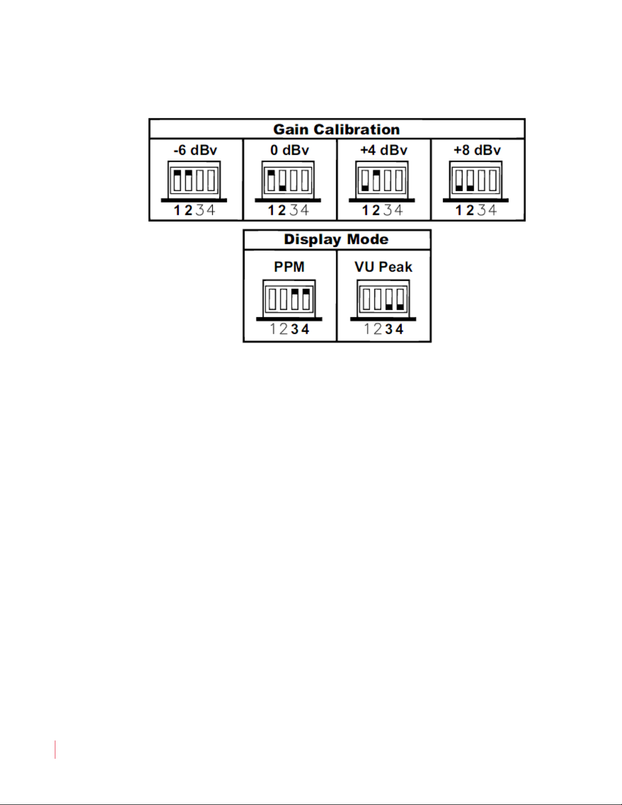
There are four sections (S1, S2, S3, S4) on each DIP switch module. The
first two sections (S1, S2) are for setting the meter input gain calibration
and the second two sections (S3, S4) are for setting the bar graph
display mode. See Figure 1–18 on page 22.
821020: AMP1A Series User Guide
© 2010 Wohler Technologies, Inc. All rights reserved.
21
Page 24
AMP1A Series User Guide
Technical Functional Overview
Figure 1–18 Meter Input Gain Calibration and
Display Mode DIP Switch Settings
Meter Input Gain Calibration Settings
DIP switch sections S1 and S2 set the meter input gain calibration,
which determines the level of the input signal that will result in a "0"
reading on the meter bar graphs. The factory setting is +4 dBv, but can
instead be set for -6 dBv, 0 dBv, or +8 dBv by the user.
Bar Graph Display Modes
DIP switch sections S3 and S4 determine how peak levels are displayed
(display mode) and select either the "PPM" mode or an auto-reset "VU
Peak" mode (not the PPM value!). The PPM mode exhibits an attack
time of 10 milliseconds and a decay time of 2 seconds from 0 to -20 dB.
The VU mode exhibits a 300 millisecond rise to 99% of full indication
and a decay of 300 milliseconds. The factory setting is VU mode.
Technical Functional Overview
22
Figure 1–19 on page 23 through Figure 1–22 on page 26 illustrate the
overall functionality of the AMP1A Series monitors.
821020: AMP1A Series User Guide
© 2010 Wohler Technologies, Inc. All rights reserved.
Page 25
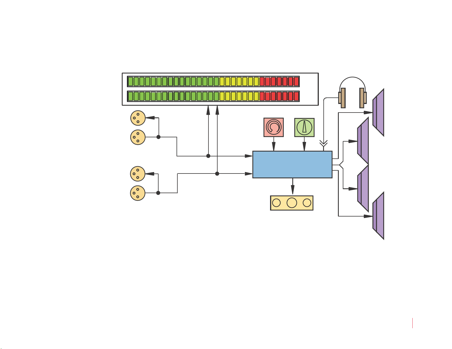
Figure 1–19 AMP1A-30 Block Diagram
Left
Speaker
Stereo Analog
Amplifier
Volume
Balance
Woofer
Speaker
Phase Indication
Right
Speaker
Headphone
Woofer
Speaker
Right
Left
Left Analog
Input (A)
Loop-Thru
Loop-Thru
Right Analog
Input (B)
Right
Left
30-Segment
High-Visibility
Level Meters
AMP1A Series User Guide
Technical Functional Overview
821020: AMP1A Series User Guide
© 2010 Wohler Technologies, Inc. All rights reserved.
23
Page 26
AMP1A Series User Guide
Headphone
Left
Speaker
Stereo Analog
Amplifier
Volume
Balance
Woofer
Speaker
Phase Indication
Right
Speaker
Woofer
Speaker
Right
Left
Left Analog
Input (A)
Loop-Thru
Loop-Thru
Right Analog
Input (B)
Right
Left
106-Segment
High-Resolution
Level Meters
Technical Functional Overview
Figure 1–20 AMP1A-106 Block Diagram
24
821020: AMP1A Series User Guide
© 2010 Wohler Technologies, Inc. All rights reserved.
Page 27
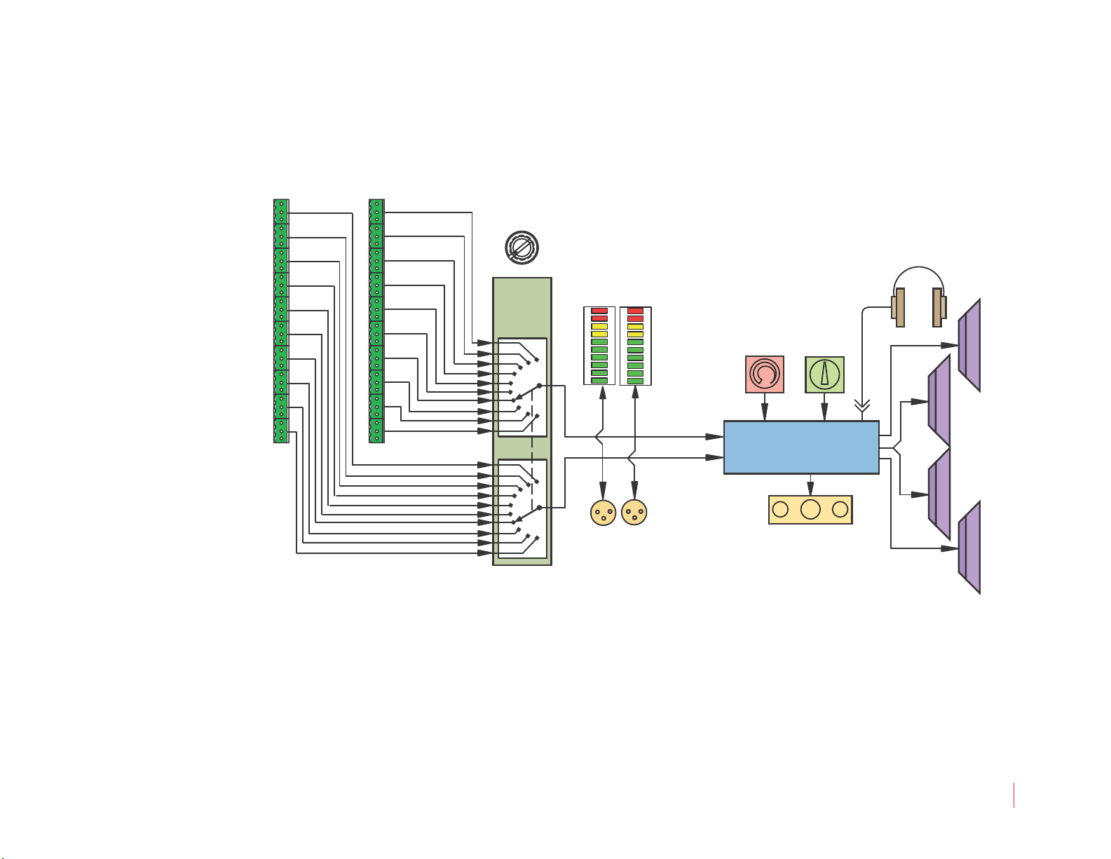
Figure 1–21 AMP1A-LP10S Block Diagram
10-Segment
Level Meters
Left
Speaker
Stereo Analog
Amplifier
Volume
Balance
Woofer
Speaker
Phase Indication
Right
Speaker
Headphone
Woofer
Speaker
Right
Left
R
L
Stereo Output of
Selected Source
9
10
3
6
8
7
Analog
Inputs
5
4
2
1
Source
Pair
Select
Right Input
Left Input
6
5
7
9
3
2
1
10
4
8
AMP1A Series User Guide
Technical Functional Overview
© 2010 Wohler Technologies, Inc. All rights reserved.
821020: AMP1A Series User Guide
25
Page 28
AMP1A Series User Guide
Left
Speaker
Stereo Analog
Amplifier
Volume
Balance
Woofer
Speaker
Right
Speaker
Headphone
Woofer
Speaker
Right Input
(Chan. B)
(Chan. A)
2
1
Left Input
Right
Left
1
2
1
2
2
1
R
L
Selected Source Output
Select
Stereo
Source
Technical Functional Overview
Figure 1–22 AMP1A Plus Block Diagram
26
821020: AMP1A Series User Guide
© 2010 Wohler Technologies, Inc. All rights reserved.
 Loading...