

Wohler AMP1-E8DA, AMP2-E8DA, AMP1-E8MDA-3G, AMP2-E8MDA-3G User Manual

AMPx-E8 Series
• AMP1-E8DA • AMP1-E8MDA-3G
• AMP2-E8DA • AMP2-E8MDA-3G
2RU, Dolby, Multi-Format, Analog/
Digital Audio Monitors
User Guide
Part Number 821016, Revision E

© 2011 Wohler Technologies, Inc. All rights reserved.
This publication is protected by federal copyright law. No part of this publication may be
copied or distributed, stored in a retrieval system, or translated into any human or computer
language in any form or by any means electronic, mechanical, manual, magnetic, or otherwise,
or disclosed to third parties without the express written permission of Wohler Technologies.
Reproduction
Licensed users and authorized distributors of Wohler Technologies, Inc. products may copy
this document for use with Wohler Technologies., Inc. products provided that the copyright
notice above is included in all reproductions.
Customer Support
Wohler Technologies, Inc.
31055 Huntwood Avenue
Hayward, CA 94544
www.wohler.com
Phone: 510-870-0810
FAX: 510-870-0811
US Toll Free: 1-888-596-4537
(1-888-5-WOHLER)
Web: www.wohler.com
Sales: sales@wohler.com
Support: support@wohler.com
Disclaimers
Even though Wohler Technologies, Inc. has tested its equipment and software, and reviewed
the documentation, Wohler Technologies, Inc. makes no warranty or representation, either
express or implied, with respect to software, documentation, their quality, performance,
merchantability, or fitness for a particular purpose.
Wohler Technologies, Inc. reserves the right to change or improve our products at any time and
without notice.
In no event will Wohler Technologies, Inc. be liable for direct, indirect, special, incidental, or
consequential damages resulting from any defect in the hardware, software, or its
documentation, even if advised of the possibility of such damages.
Some states do not allow the exclusion or limitation for incidental or consequential damages, so
the above exclusion or limitation may not apply to you.
Printing
This document is intended to be printed on a duplex printer, such that the copy appears on
both sides of each page. This ensures that all new chapters start on a right-facing page.
This document looks best when printed on a color printer since some images may be indistinct
when printed on a black and white printer.
Other Technologies and Products
Dolby, Dolby Digital (AC-3), Dolby D, Dolby E and the Dolby logo are registered trademark of
Dolby Laboratories, Inc., a licenor of technology used in this product. For more information
concerning Dolby E, Dolby Digital, and Dolby Digital (AC-3), please contact Dolby
Laboratories directly at Phone: 415-558-0200, info@dolby.com, or
Dolby Laboratories, Inc., 100 Potrero Avenue, San Francisco, CA 94103
Microsoft Windows, and Internet Explorer are registered trademarks of Microsoft Corporation.
The Tascam trademark is owned by Teac, Inc.
Last Update
June 06, 2011
821016: AMPx-E8 Series User Guide
ii
© 2011 Wohler Technologies, Inc. All rights reserved.

Table of Contents
Preface . . . . . . . . . . . . . . . . . . . . . . . . . . . . . . . . . . . . . . . ix
Introduction ..................................................................ix
Overview.................................................................ix
Topics.....................................................................ix
What’s New....................................................................x
Functionality Enhancements .............................................x
3G...........................................................................x
Software Termination .................................................x
Rear Panel Connector Arrangements ...........................xi
Chapter 1. Installation . . . . . . . . . . . . . . . . . . . . . . . . . . . .1
Introduction ...................................................................1
Overview..................................................................1
Topics......................................................................1
Safety ...........................................................................2
Important Safety Instructions ..................................... 2
Safety Symbols.........................................................3
FCC Compliance..............................................................3
Unpacking......................................................................3
Installation Recommendations...........................................4
Mounting..................................................................4
Heat Dissipation........................................................4
Sympathetic Vibration................................................4
Mechanical Bracing....................................................5
Audio Connections and Cable Recommendations............5
Electrical Interference ................................................5
Power ......................................................................6
821016: AMPx-E8 Series User Guide
© 2011 Wohler Technologies, Inc. All rights reserved.
iii

Installation.................................................................... 6
Initial Setup............................................................. 6
Power Up................................................................. 6
Chapter 2. System Overview . . . . . . . . . . . . . . . . . . . . . . . 7
Introduction................................................................... 7
Overview................................................................. 7
Topics ..................................................................... 7
Front Panel Controls........................................................ 8
Features and Simple Controls..................................... 8
LCD Screen.............................................................10
User Interface.........................................................12
Multi-Mode Color Codes ......................................12
Menu Navigation................................................13
Rear Panel Connectors ...................................................14
Input Connectors.....................................................14
Input Connectors.....................................................16
Output Connectors...................................................17
Programming and Remote Access Connectors.............. 20
RS-232 Connectors ............................................20
Remote Connector .............................................20
Rotary Switches.......................................................21
Monitoring Inputs..........................................................22
System Overview.....................................................22
Monitoring an Analog Input.......................................23
Monitoring an AES Input...........................................23
Monitoring an SDI Input ...........................................24
Monitoring a Dolby Input ..........................................24
Monitoring Dolby in SDI............................................24
Channel Selection and Mixing .........................................25
821016: AMPx-E8 Series User Guide
iv
© 2011 Wohler Technologies, Inc. All rights reserved.

Chapter 3. Audio Configuration. . . . . . . . . . . . . . . . . . . . .27
Introduction .................................................................27
Overview................................................................27
Topics....................................................................27
Analog Output Preference...............................................28
Monitoring and Mixing Modes..........................................29
Arbitrary Mixing ......................................................29
Single....................................................................30
Pairs......................................................................30
Downmix................................................................31
Muting the Speakers......................................................33
Phase Correlation..........................................................34
SDI Inputs ...................................................................35
Selecting SDI Groups and Subgroups .........................35
Dolby Decode Mode Disabled...............................35
Dolby Decode Mode Enabled ...............................36
Configuring for SDI Delay ........................................37
Selecting the Input Signal ..............................................38
Setting the Monitor’s Startup Configuration.......................39
Terminating/Unterminating Inputs ...................................40
Chapter 4. Presets. . . . . . . . . . . . . . . . . . . . . . . . . . . . . . .43
Introduction .................................................................43
Overview................................................................43
Topics....................................................................43
What are Presets? .........................................................44
Methods of Accessing the Presets ....................................44
Setup Menu............................................................44
Preset Mode............................................................44
Enabling/Disabling Preset Mode ...........................45
Recalling a Preset ..............................................45
821016: AMPx-E8 Series User Guide
© 2011 Wohler Technologies, Inc. All rights reserved.
v

Speaker Assign/Preset Buttons
(Presets 1 through 4 Only)........................................45
Saving a Preset .................................................46
Recalling a Preset ..............................................46
Overwriting a Preset...........................................46
Chapter 5. Dolby. . . . . . . . . . . . . . . . . . . . . . . . . . . . . . . . 49
Introduction..................................................................49
Overview................................................................49
Topics ....................................................................49
Dolby Input Source Selection ..........................................50
Dolby Decoding.............................................................50
PCM.............................................................................51
Dolby Metadata.............................................................52
Chapter 6. Setup Menu . . . . . . . . . . . . . . . . . . . . . . . . . . . 55
Introduction..................................................................55
Overview................................................................55
Topics ....................................................................55
Accessing Setup Mode....................................................56
Analog Output Preference Mode.......................................58
Recalling a Preset..........................................................58
Saving a Preset.............................................................59
Creating a New Preset .............................................60
Overwriting an Existing Preset...................................61
Preset Mode..................................................................63
Erasing a Preset ................. ...........................................63
SDI Delay.....................................................................64
Startup ........................................................................65
Surround Gain ..............................................................65
Bitstream Detection.......................................................66
Phase Bits ....................................................................67
821016: AMPx-E8 Series User Guide
vi
© 2011 Wohler Technologies, Inc. All rights reserved.

Chapter 7. Features and Specifications. . . . . . . . . . . . . . .69
Introduction .................................................................69
Overview................................................................69
Topics....................................................................69
Features ......................................................................70
Common Features ...................................................70
Model Distinctions ...................................................71
Specifications ...............................................................71
Technical Functional Overview.........................................74
821016: AMPx-E8 Series User Guide
© 2011 Wohler Technologies, Inc. All rights reserved.
vii


Introduction
Overview
The preface lists the new features and functionality for this release.
Topics
Topics Page
What’s New x
Preface
Functionality Enhancements x
821016: AMPx-E8 Series User Guide
© 2011 Wohler Technologies, Inc. All rights reserved.
ix
Preface
What’s New
What’s New
This release provides several changes and functionality enhancements:
• 3G functionality (now available in 1RU!)
• Signal termination moved to software control
• Phase Bits on page 67
• Bitstream Detection on page 66
Functionality Enhancements
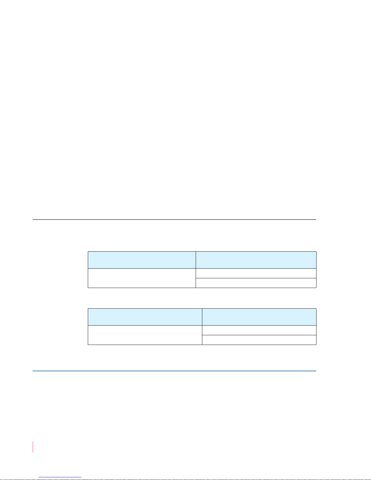
3G
In adding the 3G functionality, we have also discontinued the MDAonly models as shown in the following table:
Old Version
AMP2-E8MDA (PN 8102-0020)
Moreover, we are replacing some other similar products as well.
Old Version
AMP2-E8DA (PN 8102-0010)
Software Termination
In this release, all terminations are no longer on the rear panel; they are
now controlled by the software. Refer to Terminating/Unterminating
Inputs on page 40 for details.
New Version Replacement
Suggestions
AMP1-E8MDA-3G (PN 8102-0070)
AMP2-E8MDA-3G (PN 8102-0080)
New Version Replacement
Suggestions
AMP1-E8DA (PN 8102-0060)
AMP2-E8DA (PN 8102-0130)
821016: AMPx-E8 Series User Guide
x
© 2011 Wohler Technologies, Inc. All rights reserved.

Functionality Enhancements
Rear Panel Connector Arrangements
Note that in the process of redesigning the AMPx-E8 Series monitors,
we have rearranged the rear panels. Refer to Appendix A on page 79
for remapping information.
Preface
821016: AMPx-E8 Series User Guide
© 2011 Wohler Technologies, Inc. All rights reserved.
xi

Preface
Functionality Enhancements
821016: AMPx-E8 Series User Guide
xii
© 2011 Wohler Technologies, Inc. All rights reserved.

Introduction
Overview
This chapter describes the front panel controls and the rear panel
connectors in detail. It also describes how to use the front panel user
interface for data display and system configuration. Configuration
procedures are covered in detail in Chapter 3 on page 27.
CHAPTER 1
Installation
Topics
Topics Page
Introduction 1
Safety 2
FCC Compliance 3
Unpacking 3
Installation Recommendations 4
Installation 6
821016: AMPx-E8 Series User Guide
© 2011 Wohler Technologies, Inc. All rights reserved.
1

Chapter 1 Installation
Safety
Safety
Important Safety Instructions
1. Read, keep, and follow all of these instructions; heed all warnings.
2. Do not use this equipment near water, rain or moisture.
3. Use only a dry cloth to clean the equipment.
4. Do not block any ventilation openings. Install only in accordance
with the instructions in Installation Recommendations on page 4.
5. Do not install near any heat source such as a radiator, heat register,
amplifier, or stove.
6. Do not attempt to plug the unit into a two-blade outlet (with only
two prongs of equal width).
IMPORTANT:
By design, these monitors will only plug into a three-prong outlet for
your safety. If the plug does not fit into your outlet, contact an
electrician to replace the obsolete outlet.
7. Protect the power cord from being walked on or pinched,
particularly at plug’s source on the equipment and at the socket.
8. Use only the attachments/accessories specified by the
manufacturer.
9. Unplug the equipment during lightning storms or when unused
for long periods of time.
10. Use of a cart is neither recommended nor approved by Wohler.
11. Refer all servicing to qualified service personnel. Servicing will be
required under all of the following conditions:
• The equipment has been damaged in any way, such as when
the power-supply cord or plug is damaged.
• Objects have fallen onto the equipment; or the equipment has
been exposed to rain or moisture, or liquid has been spilled
onto the equipment.
• The equipment does not operate normally.
821016: AMPx-E8 Series User Guide
2
© 2011 Wohler Technologies, Inc. All rights reserved.
• The equipment has been dropped.
Safety Symbols
Chapter 1 Installation
FCC Compliance
WARNING:
The symbol to the left is a warning to be careful of electric shock. Do
not open the top cover with the power cord attached.
FCC Compliance
This equipment has been tested and found to comply with the limits for
a Class A digital device, pursuant to part 15 of the FCC Rules. These
limits are designed to provide reasonable protection against harmful
interference when the equipment is operated in a commercial
environment. This equipment generates, uses, and can radiate radio
frequency energy and, if not installed and used in accordance with the
instruction manual, may cause harmful interference to radio
communications. Operation of this equipment in a residential area is
likely to cause harmful interference in which case the user will be
required to correct the interference at his own expense.
Unpacking
Unpack the AMPx-E8 Series monitor and inspect for any apparent physical
damage that may have occurred in transit. If the unit has been damaged,
contact Wohler customer support for assistance. (Wohler’s contact
information is on page ii of this document.)
In addition to the monitor, the package should contain:
• A CDROM containing the product’s user guide,
• A power cord, and
821016: AMPx-E8 Series User Guide
© 2011 Wohler Technologies, Inc. All rights reserved.
3

Chapter 1 Installation
Installation Recommendations
• A warranty card
Note:
We recommend you retain the shipping carton for future
use.
Installation Recommendations
Mounting
The unit is designed to install into a standard 19" rack mounted at ear
level for best high frequency response and visual observation of the
monitor screen. Please adhere to the following clearances:
Clearance Surface
24” Front
3” Rear
2” Sides
1.75” Top and Bottom (if either radiates heat)
0” Top and Bottom (if no heat)
Heat Dissipation
The ambient temperature inside the mounting enclosure should not
exceed 40° Celsius (104° Fahrenheit). Adjacent devices can be rack
mounted (or stacked) in proximity to the unit if this temperature is not
exceeded. Otherwise, allow a 1RU (1.75”/44.45mm) space above and
below the unit for air circulation.
Important:
To reduce noise, the monitor does not have any fans. As a result, the
heat generated by the class D power amplifiers, power supplies, and
other components is vented by slots in the side of the unit. Therefore,
as a safety precaution, you must allow proper ventilation on both sides
of the unit.
Sympathetic Vibration
Sympathetic vibration from other equipment (cables, etc.,) in the rack
may be serious enough to interfere with the unit’s sound quality. The
use of thin card stock and/or felt or foam weather-stripping type
821016: AMPx-E8 Series User Guide
4
© 2011 Wohler Technologies, Inc. All rights reserved.
Chapter 1 Installation
Installation Recommendations
materials between adjacent vibrating surfaces, or tying up loose cables,
etc., may be required to stop vibrations external to the unit.
Mechanical Bracing
Even though the 2U models are fairly heavy, the chassis is securely
attached to the front panel. In addition, the chassis has mounting tabs
through which you attach it to the rack rail. This feature will reduce or
eliminate rear bracing requirements in many mobile/portable
applications. The weight of internal components is distributed fairly
evenly around the unit.
Audio Connections and Cable Recommendations
We recommend that you limit the length of the cables that you use for
feeding HD-SDI signals sources to the HD-SDI inputs of the AMPx-E8
Series units and that you use a Belden 1694A cable (or equivalent).
Note:
The connections of all DB-25 connectors are compatible with
Tascam DB-25 to XLR cable assemblies. Consult the factory
for availability. All rear panel connectors are female except
for the XLR connectors.
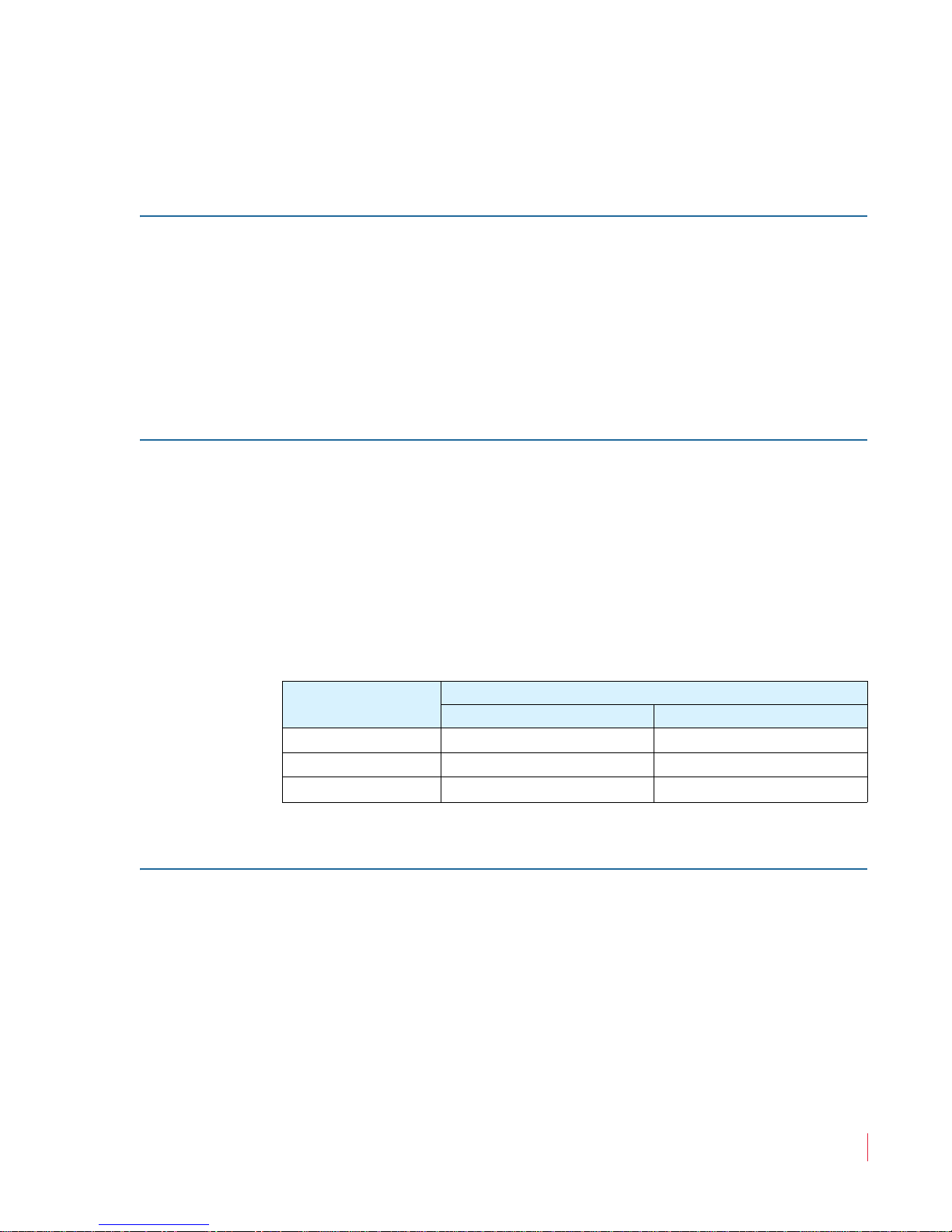
Table 1–1 Cable Length Limit Recommendations
Signal Type
SD 300 984
HD 150 492
3G 22 75
Electrical Interference
Be careful to apply proper input termination settings and avoid
mismatched cable types and other similar causes of undesired
reflections in digital signal systems. If severe enough, such reflections
can result in corruption of the digital data stream. As with any audio
equipment, maximum immunity from electrical interference requires
the use of shielded cable; however, satisfactory results can sometimes
be obtained without it. The internal circuitry ground is connected to the
chassis.
Maximum Length
Meters Feet
821016: AMPx-E8 Series User Guide
© 2011 Wohler Technologies, Inc. All rights reserved.
5

Chapter 1 Installation
Installation
Power
The unit comes with a standard 24VDC/3.0 A internal power supply
and connects an A/C mains power source (65W, 100 to 240 VAC, 50/
60Hz) through the IEC connector provided on the rear panel of the unit.
When the mains plug or appliance coupler is used as the disconnect
device, the disconnect device should remain operable.
Installation
Initial Setup
Power Up
1. Carefully install the monitor into a standard 19”-rack.
2. Connect all signal cables to and from associated equipment.
3. Connect the power cord from the monitor to A/C mains.
The AMPx-E8 Series monitors are factory-configured so that all settings
are non-volatile. When power to the unit is cycled (off/on), the unit will
restore itself so that each setting such as channel selection(s), input
type, and so on, are automatically restored to the unit’s previous
factory setting. However, you can custom configure the monitor to
automatically restore your configuration settings on power up. Refer to
Setup Menu on page 55 for details.
821016: AMPx-E8 Series User Guide
6
© 2011 Wohler Technologies, Inc. All rights reserved.

Introduction
Overview
This chapter describes how to install the AMPx-E8 Series monitor into a
standard 19”-rack and how to connect the audio cables.
Topics
CHAPTER 2
System Overview
Topics Page
Introduction 7
Front Panel Controls 8
Rear Panel Connectors 14
Monitoring Inputs 22
Channel Selection and Mixing 25
821016: AMPx-E8 Series User Guide
© 2011 Wohler Technologies, Inc. All rights reserved.
7

Chapter 2 System Overview
Front Panel Controls
Front Panel Controls
Features and Simple Controls
Refer to the images in Figure 2–1 and Figure 2–2 on the next page.
• Speakers: The AMP2s features two mid-range speakers (left and
right) and one woofer speaker. The AMP1s have two woofers. All
models of the AMPx-X8 Series contain high performance
transducers driven by three power amplifiers. Two amplifier/
driver combinations handle midrange and high frequency
information in the left and right (stereo) speaker channels, while the
third channel reproduces and sums the left and right channel
information below the crossover point in the woofer (bass) speaker.
Note that the woofer channel is not a dedicated LFE (sub-woofer) or
center channel.
• Level Meters (1 through 8): Source channels 1 through 8 are
displayed through eight audio level meters (four on the left side;
four on the right side). These level meters, high-resolution LED bar
graph displays and feature a dynamic range of 66 dB with PPM dot
over VU bar ballistic characteristics.
• Headphones (1/4” Jack): Select the headphone audio sources as
you would for the internal speakers. When you plug in headphones
the speakers will mute.
• Volume (Rotary Knob): This control adjusts the loudness of the
audio reproduced by the internal speaker channels or connected
headphones.
• Balance (Rotary Knob): This control adjusts the volume balance
between the left and right speaker channels. Note that this control
attenuates the signal from the source, so that the left and right bass
frequencies (summed together and reproduced in the woofer
channel) will respond to balance adjustments in tandem with the
left and right speaker channels.
• Level Meter Brightness (Potentiometers, Left and Right): Use a
small slot screwdriver to adjust the brightness of the bar graph
meters using these two recessed trim pot controls. The left control
adjusts the brightness of the left four LED bar graphs and the right
821016: AMPx-E8 Series User Guide
8
© 2011 Wohler Technologies, Inc. All rights reserved.
821016: AMPx-E8 Series User Guide
© 2011 Wohler Technologies, Inc. All rights reserved.
9
Chapter 2 System Overview
Front Panel Controls
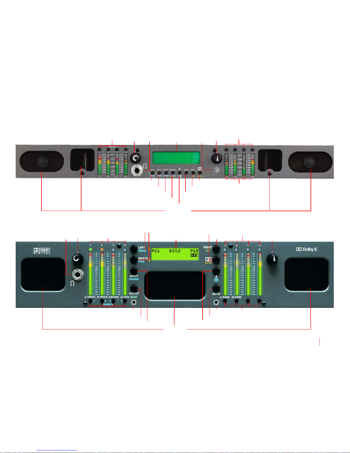
Figure 2–1 AMP1-E8 Series Front Panel
Figure 2–2 AMP2-E8 Series Front Panel
Speakers
Level
Meters
Headphones Speaker AssignVolume LCD Screen Balance
Metadata/Pairs/Down
Left/Single/Up
Dolby/Enter
Right/Up/Escape
Brightness
Mute
Phase/Function
Group/Setup
Input/Downmix
Speaker Assign/ Presets
Speakers
Speaker Assign/ Presets
Meters/Speaker Assign LEDs
Speaker
Headphones
Meters/Speaker Assign LEDs
Volume LCD Screen Balance
Brightness (R)
Metadata/Pairs/DownLeft/Single/Up Dolby/Enter
Right/Escape
Brightness (L)
Mute
Phase/Function
Group/Setup
Input/Downmix

Chapter 2 System Overview
Front Panel Controls
control adjusts the brightness of the right four bar graphs.
Clockwise rotation increases the brightness.
• Speaker Assign LEDs (1 through 8, Left and Right): These LEDs
• Speaker Assign/Preset Buttons (Speaker Assign, 1 through 8;
LCD Screen
Note:
The AMP1s only have one brightness control.
indicate the speaker mix of selected channels. The speaker assign
LEDs are located above each of the 53-segment bar graphs.
Note:
In the AMP1s, the speaker assign LEDs are the top
segment of the meters.
In addition, on the AMP1s, the top LED segment of each bar graph
serves as the speaker assign LED for the respective channel.
Preset Buttons, 1 through 4): Pressing any of these buttons selects
the channels to be summed into either or both speaker channels, or
to create and recall presets when used in conjunction with the
FN
button. Refer to Chapter 4 on page 43 for more information about
presets.
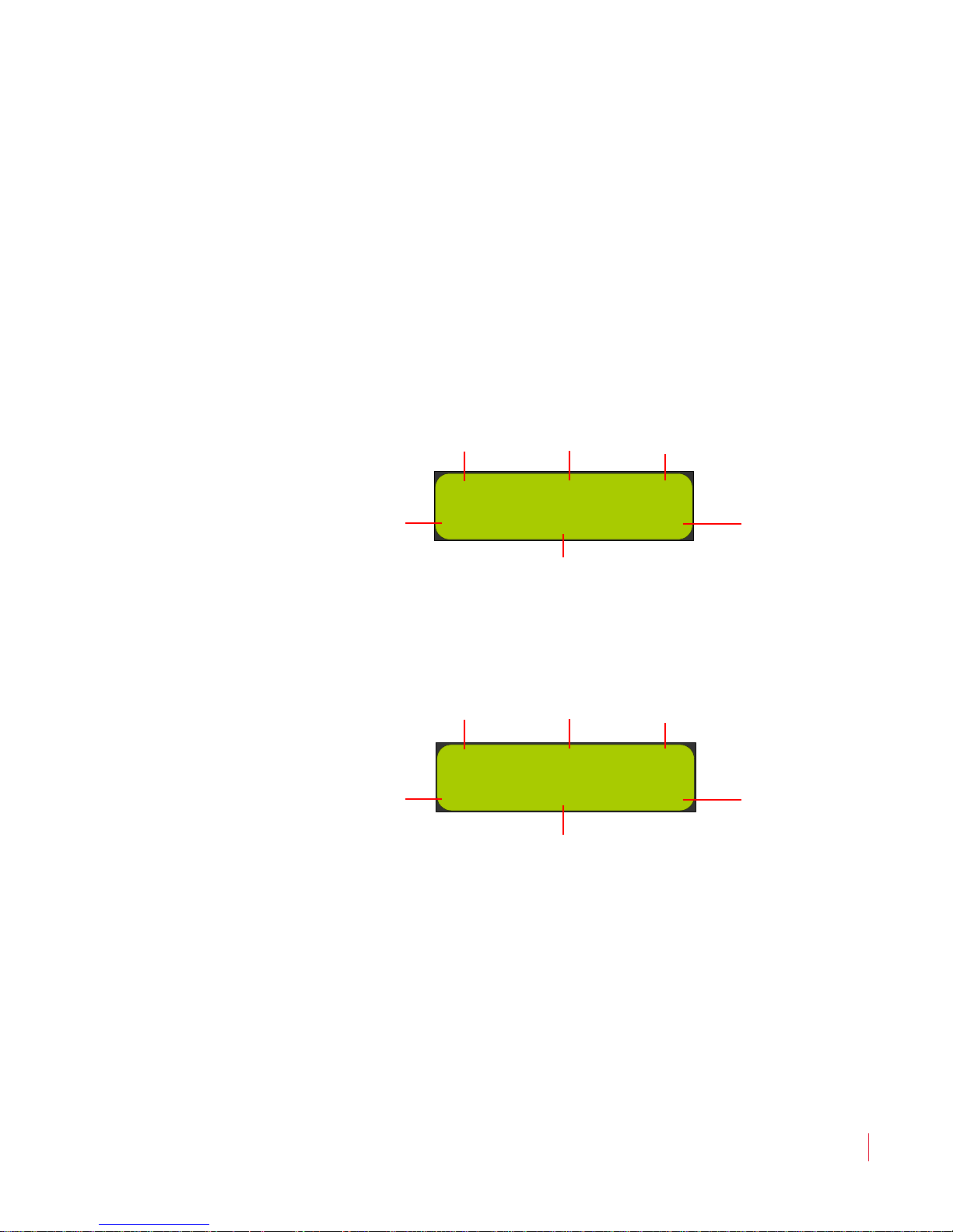
The LCD screen displays various parameters and settings, and is also
used to configure/program the monitor. The features of the LCD
screen (shown in Figure 2–3 through Figure 2–6) include:
• Mix Status: Displayed on the top right and top left corners of the
LCD screen, the Mix Status indicates how the current input signal
is mixed to the internal speakers.
• Source Status: Displayed in the top center of the LCD screen, the
Source Status indicates the current signal type and current input
currently audible in the internal speakers. If a preset has been
recalled, this area displays the name of the preset until a monitoring
or input change is made.
• SDI Groups/Dolby Signal Type: Displayed in the bottom left and
bottom right corners of the LCD screen, these groups indicate the
SDI channels that are currently mixed to the internal speakers. In
the case when a Dolby signal is mixed to the internal speakers, the
bottom left corner will be blank and the bottom right corner will
display the Dolby logo, PCM, DAT, or --- (no input signal).
821016: AMPx-E8 Series User Guide
10
© 2011 Wohler Technologies, Inc. All rights reserved.
Chapter 2 System Overview
DM3 SD.SDI2 DM3
1 3 5 7
2 4 6 8
GP1
GP2
Source Status
(SD-SDI Input 2)
Mix Status
(Downmix 3)
Mix Status
(Downmix 3)
Input Lock Status
(Channels 1 through 8 Locked)
SDI Group
(Group #2)
SDI Group
(Group #1)
MIX HD.SDI1 MIX
5 7
-- 6 8
GP3
GP4
Source Status
(HD-SDI Input 1)
Mix Status
(Custom)
Mix Status
(Custom)
Input Lock Status
(Channels 1 through 4 Not Locked;
Channels 5 through 8 Locked)
SDI Group
(Group #4)
SDI Group
(Group #3)
Front Panel Controls
• Input Lock Status (Digital Inputs Only): Displayed in the center of
bottom line, the Input Lock Status shows the lock status of the
selected digital input(s). If any input channel pairs are not locked,
then they will display as short dashes. Each dash (-) indicates a
position for displaying the channel pairs available for monitoring
from left to right: 1/2, 3/4, 5/6 and 7/8. The unit updates the
Lock Status
whenever it detects a signal change.
Input
See Figure 2–3 below through Figure 2–6 on page 12 for additional
examples.
Figure 2–3 Status Display Example: Standard Input
Source - SD-SDI Input 2
Figure 2–4 Status Display Example: Standard Input
Source - HD-SDI Input 1
© 2011 Wohler Technologies, Inc. All rights reserved.
821016: AMPx-E8 Series User Guide
11
Chapter 2 System Overview
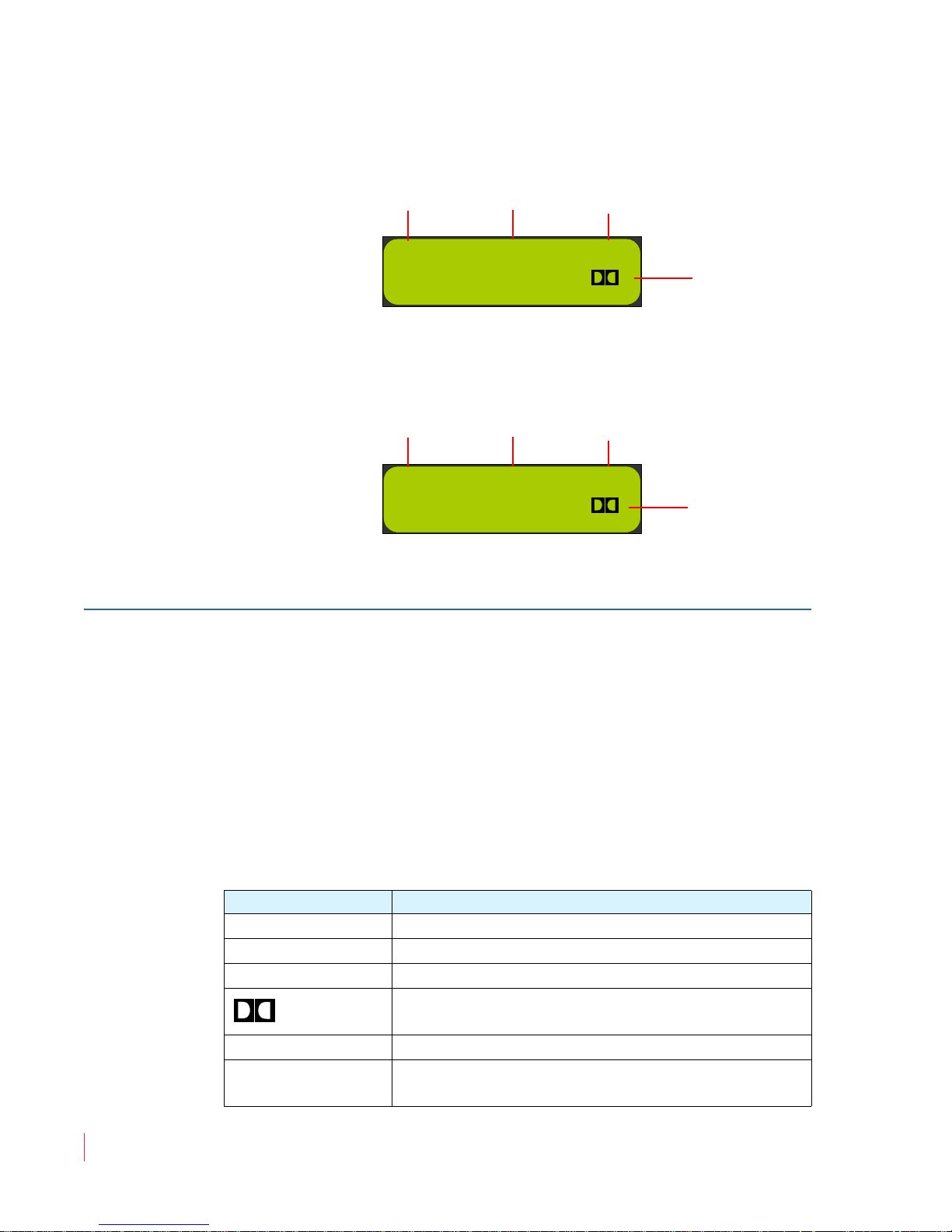
PG1 BSt1 PG1
E
Source Status
(Bitstream 1
Program Status
(Program 1)
Program Status
(Program 1)
Bitstream Type
(Dolby E)
PG1 BSt2 PG1
D
Source Status
(Bitstream 2)
Program Status
(Program 1)
Program Status
(Program 1)
Bitstream Type
(Dolby D)
Front Panel Controls
Figure 2–5 Status Display Example: Dolby Input
Figure 2–6 Status Display Example: Dolby Input
Source - Bitstream 1
Source - Bitstream 2
User Interface
Multi-Mode Color Codes
Most of the user interface buttons are multi-functional. They affect the
unit differently depending on whether they are used alone or in
combination with another button. The monitor’s front panels have
color-coded legends to help identify the different functions of each
button:
• White indicates normal operation.
Table 2–1 White Control Functionality
Button Functionality
Left
Right
MData
Input
821016: AMPx-E8 Series User Guide
12
© 2011 Wohler Technologies, Inc. All rights reserved.
Displays the next channel to the left
Displays the next channel to the right
Selects Dolby metadata for display
Toggles between using the Dolby Decode mode
or not
Selects inputs for monitoring
Displays the phase correlation for the currently-
monitored input pairs
Chapter 2 System Overview
Front Panel Controls
Table 2–1 White Control Functionality (Continued)
Button Functionality
Group
Mute
Selects the channel groups and subgroups for an
SDI signal
Mutes the audio currently playing in the front
panel speakers
• Blue for functions controlled by the Fn button.
Table 2–2 Blue Control Functionality
Button Functionality
Fn + Single
Fn + Pairs
Fn + Downmix
Fn + Setup
Selects single channel monitoring mode: one
channel per speaker, selected independently
Selects pair monitoring mode: one channel per
speaker, selected pair by pair
Selects downmix mode: one of several available
downmixes
Displays the Setup menu
• Yellow indicates the button functions for the Setup menu. Refer to
Chapter 6 on page 55 for more details about using the Setup menu
for system configuration.
Table 2–3 Yellow Control Functionality
Button Functionality
Esc
Enter
Displays the previous menu item
Displays the next menu item
Returns to the previous menu and cancels
changes
Returns to the previous menu and saves changes
Menu Navigation
When making changes to the Setup menu, you will generally press the
Enter button to select menu options and settings, and press the Esc
(Escape) button to back out of the menu, setting, or display to return to
normal operation.
821016: AMPx-E8 Series User Guide
© 2011 Wohler Technologies, Inc. All rights reserved.
13
Chapter 2 System Overview
Rear Panel Connectors
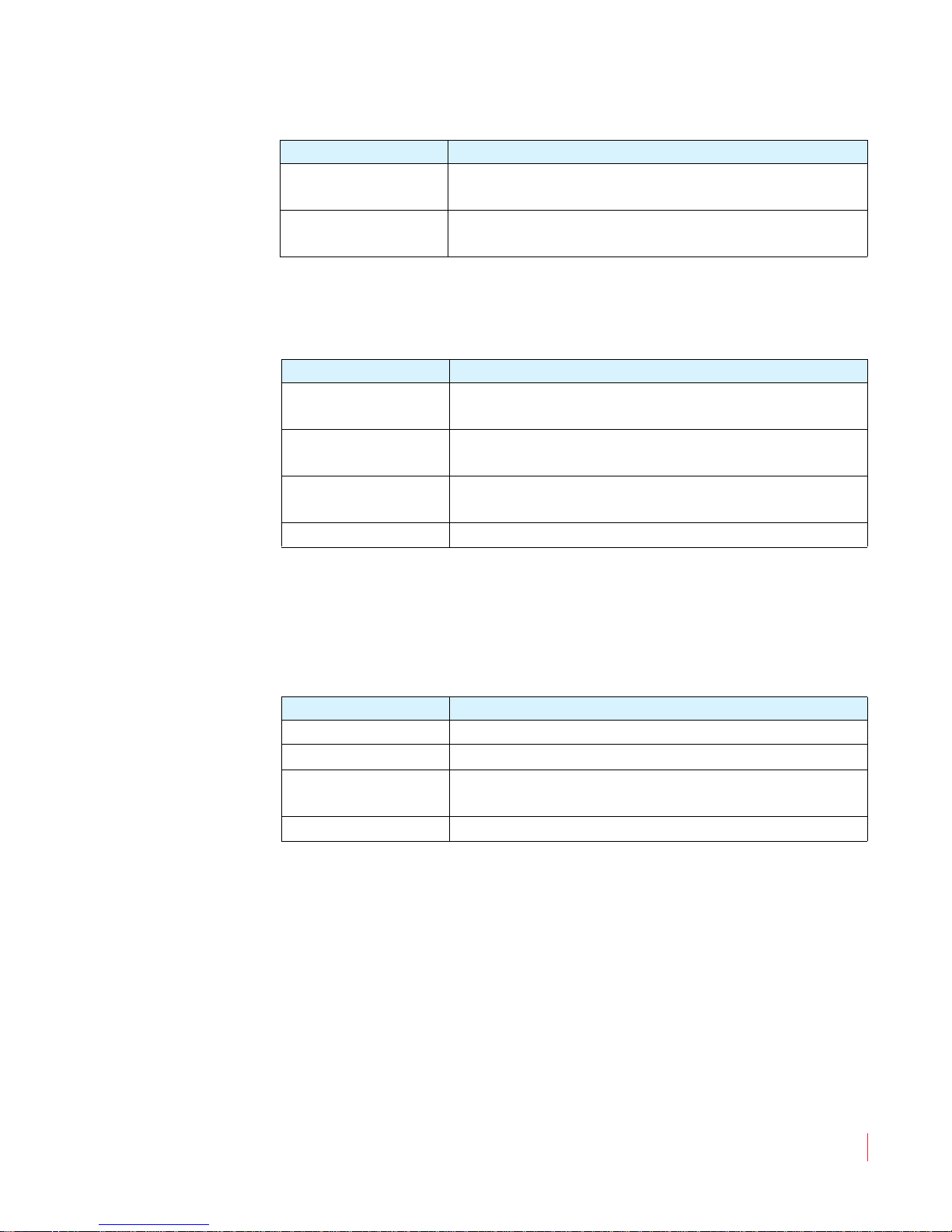
Rear Panel Connectors
• Analog In (DB-25-F): This connector accepts balanced, low
impedance, line level analog signals. See Figure 2–7 below for pinout information.
Figure 2–7 Analog Input Connector Pin-Out
Input Connectors
• Power: Attach a standard IEC-320 power cord between this
connector and AC mains power.
• AES/PCM In (1 through 4, BNC-F): These connectors accept
unbalanced (75 ) PCM (AES/EBU) formatted signals. These inputs
appear as AES1 in the LCD screen.
If you are not connecting downstream equipment, then you should
terminate the selected input connector. Otherwise, unterminate
them.
• AES/PCM In (and Loop Out) (DB-25-F): This connector accepts
balanced (110 ) AES signals. Inputs are internally connected to the
loop-through outputs. These inputs are referred to as AES2 in the
LCD screen. If you are connecting downstream equipment to the
AES loop-through outputs of this connector, then you should
unterminate this connector. If you are not connecting downstream
equipment, then you should terminate them. Refer to Terminating/
Unterminating Inputs on page 40 for details.
Note:
821016: AMPx-E8 Series User Guide
14
© 2011 Wohler Technologies, Inc. All rights reserved.
The pin-out for this connector is compatible with
Tascam DB-25 to XLR cable assemblies. Contact your
Wohler sales representative for availability. (Wohler’s
contact information is on page ii of this document.)

821016: AMPx-E8 Series User Guide
© 2011 Wohler Technologies, Inc. All rights reserved.
15
Chapter 2 System Overview
Rear Panel Connectors
Figure 2–8 The AMP1-E8MDA-3G Rear Panel
Figure 2–9 The AMP2-E8MDA-3G Rear Panel
Note that the DA models do not have SDI connectors.
Power
SDI Option 2
SDI In (1 & 2)
SDI Re-Clocked Out
Reference
AES Bal In & Loop Out
AES/PCM In (1 thru 4)
Analog In
Selected/Downmix
Analog Out (L&R)
AES Out from SDI
RS-232 B
Metered Analog Out
Decoded Dolby E/AC-3 Out
(1 thru 4), Mix, and In (1 & 2)
RS-232C
RS-232 A
OPT 1
Power
RS-232C
SDI In (1 & 2)
SDI Re-Clocked Out
Ref
AES Bal In &
Loop Out
Analog In
Selected/Downmix
Analog Out (L&R)
Remote
Metered Analog Out
AES/PCM In (1 thru 4)
Decoded Dolby E/AC-3 Out
(1 thru 4), Mix, and In (1 & 2)
RS-232A
RS-232B
Opt 1
Balanced AES Out from SDI
Opt 2
 Loading...