

Wohler AMP2-16V-M, AMP2-E16V-M User Manual

AMP2-16V Series
• AMP2-16V-M • AMP2-E16V-M
Modular Audio/Video
Management and Monitoring
Platform
User Guide
(Software Release: V7.xx)
Part Number 821116, Revision M

© 2017 Wohler Technologies, Inc. All rights reserved.
This publication is protected by federal copyright law. No part of this publication may be copied or distributed, stored in
a retrieval system, or translated into any human or computer language in any form or by any means electronic,
mechanical, manual, magnetic, or otherwise, or disclosed to third parties without the express written permission of
Wohler Technologies.
Reproduction
Licensed users and authorized distributors of Wohler Technologies, Inc. products may copy this document for use with
Wohler Technologies., Inc. products provided that the copyright notice above is included in all reproductions.
Customer Support
Wohler Technologies, Inc. 31055 Huntwood Avenue
Hayward, CA 94544 www.wohler.com
Phone: 510-870-0810
FAX: 510-870-0811
US Toll Free: 1-888-596-4537 (1-888-5-WOHLER)
Web: www.wohler.com Sales: sales@wohler.com
Support: support@wohler.com
Disclaimers
Even though Wohler Technologies, Inc. has tested its equipment and software, and reviewed the documentation,
Wohler Technologies, Inc makes no warranty or representation, either express or implied, with respect to software,
documentation, their quality, performance, merchantability, or fitness for a particular purpose.
In no event will Wohler Technologies, Inc. be liable for direct, indirect, special, incidental, or consequential damages
resulting from any defect in the hardware, software, or its documentation, even if advised of the possibility of such
damages.
Some states do not allow the exclusion or limitation for incidental or consequential damages, so the above exclusion
or limitation may not apply to you.
Printing
This document looks best when printed on a color printer since some images may be indistinct when printed on a
black and white printer.
PDF
All text strings appearing in this shade of blue are hyperlinks.
Other Technologies and Products
Dolby is a registered trademark of Dolby Laboratories, Inc.
Microsoft Windows, and Internet Explorer are registered trademarks of Microsoft Corporation.
Dante is a registered trademark of Audinate Pty Ltd.
Ravenna is a registered trademark of ALC NetworX GmbH.
Bach is a registered trademark of Coveloz.
Last Update
May 8, 2017

TABLE OF CONTENTS
Contents
TABLE OF CONTENTS .................................................................................. iii
Contents ........................................................................................................ iii
PREFACE .................................................................................................... 1
New Features .................................................................................................. 1
Overview .................................................................................................. 1
What’s New? ............................................................................................. 1
CHAPTER 1: Quick Start ............................................................................... 2
Introduction .................................................................................................... 2
Overview .................................................................................................. 2
Front Panel Features .................................................................................. 2
User Interface ................................................................................................. 3
Meters and Data Screens ............................................................................ 3
Help ......................................................................................................... 4
Setting Up Your Monitor for the First Time .................................................... 5
1. Configure the Monitor Mixer ..................................................................... 5
2. Create Channel Clusters .......................................................................... 6
3. Arrange the Main Screens ....................................................................... 8
4. Select the Metadata to Display on the Screen ............................................ 9
5. Save Your Setup in a Preset ................................................................... 13
Getting Support ............................................................................................. 14
CHAPTER 2: Installation ............................................................................. 15
Introduction .................................................................................................. 15
Overview ................................................................................................ 15
Important Safety Instructions.................................................................... 15
Installation Recommendations ......................................................................... 16
Mounting ................................................................................................ 16
Heat Dissipation ...................................................................................... 16
Sympathetic Vibration .............................................................................. 16
Mechanical Bracing .................................................................................. 16
Connections and Cable Recommendations ................................................... 17
Electrical Interference .............................................................................. 17
Power ..................................................................................................... 17
Compliance ................................................................................................... 17
FCC ........................................................................................................ 17
ICES-003 ................................................................................................ 17
Rear Panel Connectors .................................................................................... 18
Standard Connectors ................................................................................ 18
Optional I/O Modules and Rear Panel Connectors ......................................... 18
Basic Connections .................................................................................... 19
CHAPTER 3: The “How Do I...” Chapter .......................................................... 20
Introduction .................................................................................................. 20
Overview ................................................................................................ 20
Notation ................................................................................................. 20
Frequently Asked Questions ............................................................................ 22
How Do I Select the Inputs I Want to Hear in the Speakers? ......................... 22

How Do I Cluster Meters Pairs Together for Easy Readability? ........................ 23
How Do I View the Loudness Screen? ......................................................... 24
How Do I Set the Way Loudness is Calculated? ............................................ 25
How Do I Set Up for External Surround Sound? ........................................... 26
How Do I Configure a Stereo Downmix for My External Surround Sound? ....... 28
How Do I Synchronize Internal Speaker Audio with an External Video Source? 29
How Do I Synchronize External Surround Sound Audio with Video? ................ 30
How Do I Monitor Dolby Bitstreams? .......................................................... 31
How Do I Decode and Monitor a Single Dolby Bitstream? .............................. 33
How do I Display Dolby CRC Error Counts?.................................................. 35
How do I Display Dolby E Line Number (Guard Band)? ................................. 36
How Do I Use Presets to Change Inputs? .................................................... 38
How Do I Quickly Recall Presets from the Main Screen? ................................ 39
How Do I Set Up a SuperPair to Monitor Intercom or Other Sources? ................. 40
How Do I Set Up a SuperPair Volume Control? ............................................. 41
How Do I Mix Any Input(s) to Any Output(s)?.............................................. 42
How Do I Adjust Mixer Levels from the Main Screen? ................................... 43
How do I Show Mixer Output Levels on the Level Meters? ............................. 44
How Do I Configure the Audio Inputs or Outputs? ........................................ 45
How Do I Set the Clock Source? ................................................................ 46
How Do I Terminate/Unterminate AES Inputs? ............................................. 47
How Do I Lock Entry to the Menus? ............................................................ 48
How Do I Find Software Version Information? .............................................. 49
CHAPTER 4: Features and Screens ............................................................... 50
Introduction .................................................................................................. 50
Main Screen .................................................................................................. 50
Simultaneous Multi-Format Monitoring .............................................................. 51
Monitoring Cluster Selection ............................................................................ 51
Main Screen Arrangements ............................................................................. 51
Instant Stereo Downmix ................................................................................. 54
Loudness Monitoring ...................................................................................... 54
Loudness Screen............................................................................................ 54
High Quality Audio System .............................................................................. 56
Internal Router and Mixer ............................................................................... 56
Audio Processor Cards .................................................................................... 58
Genlock Input................................................................................................ 59
Audio Monitoring Delay ................................................................................... 59
SDI Input Audio Monitoring Delay .................................................................... 59
SDI Output Re-Embedding .............................................................................. 59
Toslink (SPDIF) Optical Input .......................................................................... 59
Wide Selection of Video Formats ...................................................................... 60
Dolby E Line Position Display ........................................................................... 61
Dolby CRC Error Counter Display ..................................................................... 61
Dolby Zoom Screen ........................................................................................ 61
SuperPair Input ............................................................................................. 63
Standard and Custom Meter Scales .................................................................. 63
Phase Monitoring ........................................................................................... 64
Status/Metadata Hot Keys .............................................................................. 64
32 Complete System Presets ........................................................................... 64
Automated Preset Changes ............................................................................. 64
Bright, Clear Displays ..................................................................................... 64
Menu Lock .................................................................................................... 64
CHAPTER 5: Menu List................................................................................ 65

Introduction .................................................................................................. 65
Menu Navigation Overview .............................................................................. 65
3G SDI I/O Configuration Menu ....................................................................... 67
5.1 Downmix Parameters Screen ..................................................................... 69
AES Input Configuration Menu ......................................................................... 70
AES/Analog Output Configuration Menus........................................................... 71
Follow Monitor Mode Controls .................................................................... 72
Free Mix Mode Controls ............................................................................ 73
Arbitrary Phase Measurement Menu ................................................................. 74
Audio Processor Card Menu ............................................................................. 75
Automation Menu........................................................................................... 77
Controls .................................................................................................. 78
Adding an Auto Mode Hot Key ......................................................................... 79
Cluster Configuration Screen ........................................................................... 80
Configuration Selection Menu .......................................................................... 81
Dolby Decoder Configuration Menu .................................................................. 82
Ethernet Setup Screen ................................................................................... 87
Hardware Configuration Menu ......................................................................... 88
Hot Key Configuration Menu 1 Through 8 .......................................................... 90
Hot Key Configuration Menu 9 Through 16 ........................................................ 91
Label Menu ................................................................................................... 92
Loudness Clusters Menu ................................................................................. 93
Loudness Measurement Menu .......................................................................... 94
Main Screen Configuration Menu ...................................................................... 96
Metadata Select Menu .................................................................................... 97
Meter Configuration Menu ............................................................................... 99
Monitor Mixer Configuration Menu .................................................................. 101
Option Configuration Menu ............................................................................ 104
Preset Management Menu ............................................................................. 105
Select Menu Lock Combination ...................................................................... 106
SMTPE 2020 Configuration Menu ................................................................... 108
Status Select Menu ...................................................................................... 109
Unit Information Menu .................................................................................. 110
CHAPTER 6: I/O Modules and Options ........................................................ 112
Introduction ................................................................................................ 112
Distinctions Among Models ............................................................................ 112
Optional I/O Modules.............................................................................. 112
Standard Models .................................................................................... 113
Menu Modifications for I/O Modules .......................................................... 113
3G/HD/SD-SDI Card .................................................................................... 114
3G/HD/SD-SDI Rear Panel Adaptor .......................................................... 114
Menu Modifications: Inputs ..................................................................... 114
Menu Modifications: Outputs ................................................................... 114
Connector Pin Outs ................................................................................ 115
AES Input Card ............................................................................................ 116
AES Input Rear Panel Adaptor ................................................................. 116
Menu Modifications................................................................................. 116
AES Output Card ......................................................................................... 117
AES Output Rear Panel Adaptor ............................................................... 117
Menu Modifications................................................................................. 117
AVB Listener Card ........................................................................................ 118
AVB Listener Rear Panel Adaptor ............................................................. 118

Menu Modifications................................................................................. 118
Analog I/O Card........................................................................................... 119
Analog Rear Panel Adaptor ...................................................................... 119
Menu Modifications................................................................................. 119
Connector Pin Outs ................................................................................ 119
Analog I/O and SPDIF TOSLINK Card ............................................................. 122
Rear Panel Adaptor ................................................................................ 122
Menu Modifications ................................................................................. 122
Connector Pin-Outs ................................................................................ 122
Dolby D/E/DD+ Card .................................................................................... 123
Menu Modifications ................................................................................. 123
Dante AoIP Receiver Card ............................................................................. 123
Dante Rear Panel Adaptor ....................................................................... 123
Menu Modifications................................................................................. 123
Ravenna AoIP Receiver Card ......................................................................... 124
Ravenna Rear Panel Adaptor ................................................................... 124
Menu Modifications................................................................................. 124
Adding a Redundant Power Supply ................................................................. 125
Precautions ........................................................................................... 125
Requirements ........................................................................................ 125
Adding the AC Power Supply ................................................................... 125
Adding the DC Power Module ................................................................... 126
Adding/Removing Modules ............................................................................ 128
Precautions ........................................................................................... 128
Requirements ........................................................................................ 128
Adding a Dolby D/E/DD+ Card ................................................................ 129
Removing a Dolby D/E/DD+ Card ............................................................ 135
Adding an I/O Module ................................................................................... 135
Adding a 3G Option Card ........................................................................ 135
Adding a Non-3G Card I/O Module ........................................................... 136
Removing an I/O Module ........................................................................ 137
Option Kits .................................................................................................. 138
CHAPTER 7: Specifications ........................................................................ 140
Introduction ................................................................................................ 140
Compliance ........................................................................................... 140
Standards ............................................................................................. 140
Specifications ........................................................................................ 140
CHAPTER 8: Troubleshooting .................................................................... 142
Introduction ................................................................................................ 142
Normal Messages ......................................................................................... 142
No IP Address ....................................................................................... 142
Inconsistent Module List .......................................................................... 142
Restart ................................................................................................. 143
Error Messages ............................................................................................ 144
Front Panel Error ................................................................................... 144
Minor Issue ........................................................................................... 144
Serial Port Access .................................................................................. 145
APPENDIX A: Dante Network Setup ........................................................... 146
Introduction ................................................................................................ 146
Dante Input Module Features ........................................................................ 146
DANTE-Compatible Listener .................................................................... 146
AVB Ethernet Features ................................... Error! Bookmark not defined.
Brooklyn II™ Controller Interface ............................................................. 147
Routing to the AMP2-16V .............................................................................. 148
What is in the AMP2-16V for Dante ................................................................ 149

Dante Device Setup ..................................................................................... 150
Dante Clock Selection ................................................................................... 151
Channel Names ........................................................................................... 151
AES67 ........................................................................................................ 152
Device Lock................................................................................................. 153
Troubleshooting ........................................................................................... 154
Dante Firmware Upgrades ............................................................................. 154
APPENDIX B: Ravenna Network Setup ........................................................ 155
Introduction ................................................................................................ 155
Ravenna Input Module Features ..................................................................... 155
RAVENNA-Compatible Listener ................................................................ 155
AVB Ethernet Features ........................................................................... 156
BACH™ Controller Interface .................................................................... 156
Home Page ................................................................................................. 157
Configuration/Device Management ................................................................. 157
Controller Cloud ........................................................................................... 159
Sync .......................................................................................................... 160
Source Streams ........................................................................................... 161
Stream Destinations ..................................................................................... 162
Patch Panel ................................................................................................. 164
Troubleshooting ........................................................................................... 165
Ravenna Firmware Upgrades ......................................................................... 165

Page 1
PREFACE
New Features
Overview
The preface lists the new features and functionality for this release.
What’s New?
There is now support for the 16-channel Dante Receiver card. Appendix A describes
how to set it up within an existing Dante AoIP network.
There is also support for the 16-channel Ravenna Receiver card. Appendix B
describes how to set it up within an existing Ravenna AoIP network.
Page 2
Volume
Balance
Headphone
Jack
Left
Speaker
Right
Speaker
Left Screen
Right Screen
Navigation Buttons
Hot Keys / Menu Knobs
CHAPTER 1: Quick Start
Introduction
Overview
This chapter describes how to use the front panel controls and the user interface
menu system. For a more in-depth description of each menu, refer to Chapter 5:
Menu List.
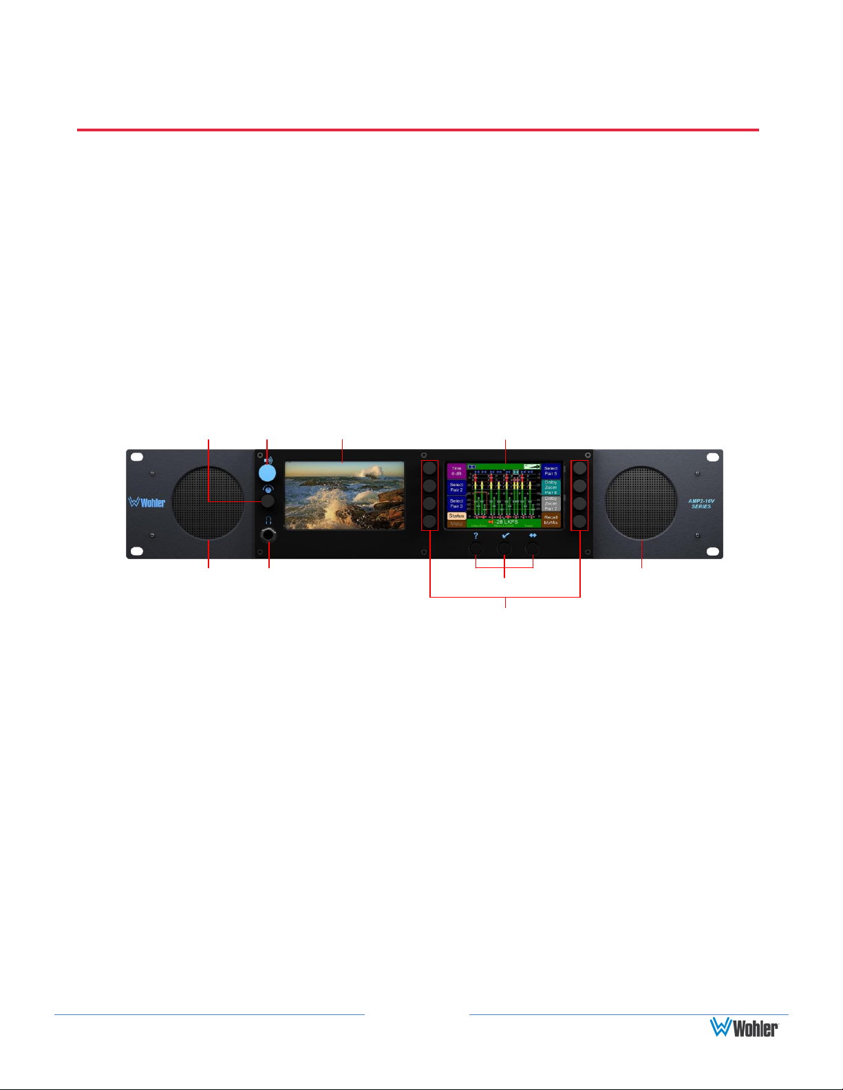
Front Panel Features
This section describes the controls on the front panel.
Figure 1–1: Front Panel Layout
1. Speakers: Two Class D amplifiers drive two (left/right) full range speakers.
2. Headphone Jack: 1/4” stereo jack for optional headphones.
3. Balance and Volume Knobs: The top knob controls the Volume. Pressing
this control sequences through a 20 dB speaker dip, mute, and then back to
the current volume. The bottom knob adjusts the Balance between the
speakers. Pressing the knob returns the audio balance to center. Rotating
either knob displays the change graphically in the screen header when the
Main Screen is displayed. The Balance knob can be changed to a Volume
knob for the SuperPair. Refer to How Do I Set Up a SuperPair Volume
Control? in Chapter 3.
4. Navigation Buttons: The three buttons below the right screen typically
provide Help (left), Save/Exit (center), and Cancel (right) functions for the
configuration menus. Some menus will have other functions for these
buttons, that are labeled at the bottom of the screen.
5. Left Screen: You can configure this screen to display video, meters, or
Page 3
-28.1 LKFS
SwapVideo/Data
Meta
+0
Dolby
Zoom
Pair 6
Recall
MyMix
Anlg
1
Dolby
5.1
AES 1
Down
Mix
Status
Menu
-60
0
-60
-50
-40
-30
-10
-20
-10
-20
-30
-40
-50
Φ Φ
-60
0
D
o
l
b
y
5
.
1
D
o
w
n
M
i
x
A
E
S
1
A
E
S
2
A
n
l
g
1
A
n
l
g
2
Anlg
2
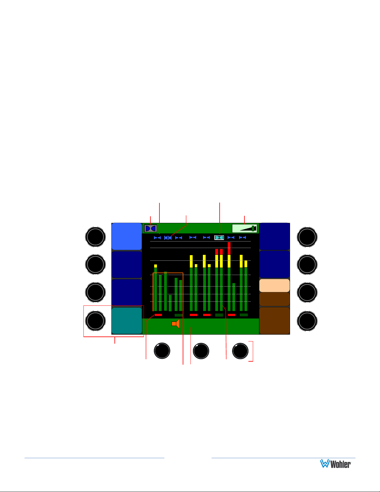
The Dolby logo indicates
the Dolby Card is installed.
Speaker Indicators:
Left and Right
Speaker Indicators:
Both
Dolby Signal
Volume
Indicator
The measured Loudness
of the selected channel
cluster is displayed
graphically and digitally.
Phase
Indicators
Level
Meters
Hot Keys and Hot
Key Descriptions
Navigation
Buttons
metadata.
6. Right Screen: You can configure this screen to display meters, metadata, or
the configuration menus and context-sensitive help.
7. Rotary Knobs: You can use the rotary knobs in two ways: by turning the
knob either clockwise or counter-clockwise, or by pressing the knob like a
button. These eight knobs provide menu navigation and hot key functions.
User Interface
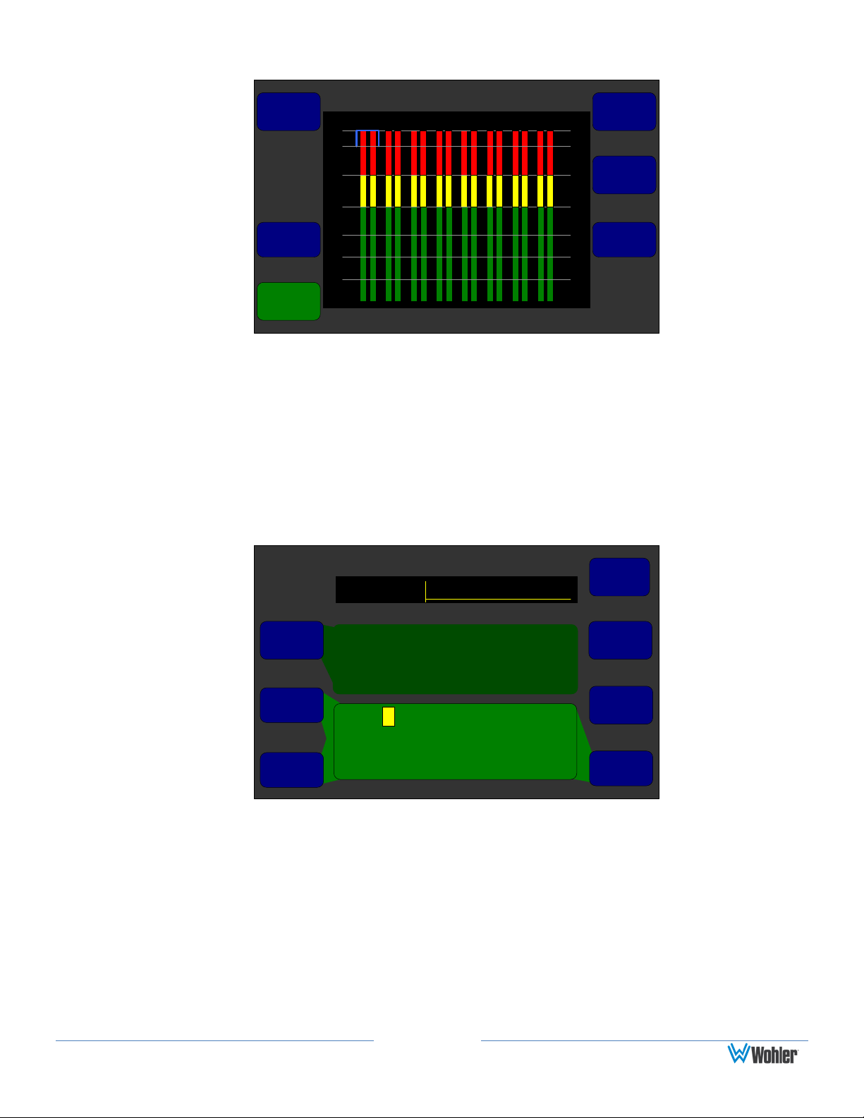
Meters and Data Screens
You can select the arrangement of meters, video, and data in five possible
configurations on the Main Screen Configuration Menu. In our example in Figure
1–2 below, the Video/Data button will switch the left screen display from video to
data.
Figure 1–2: Main Screen
Page 4
Preset Management Menu
Save / ExitHelp Cancel
Preset 4:
User Preset 4
Preset 1:
User Preset 1
Preset 1:
User Preset 1
Current Config
User Preset 1
Preset 1:
User Preset 1
Preset 4:
User Preset 4
Clear
Preset
Rename
Preset
Save
Current
Config
Copy
From
Copy To
Recall
On
Powerup
Press a control to display
help.
Preset Management Menu
Save / ExitHelp Cancel
Preset 4:
User Preset 4
Preset 1:
User Preset 1
Preset 1:
User Preset 1
Current Config
User Preset 1
Preset 1:
User Preset 1
Preset 4:
User Preset 4
Clear
Preset
Rename
Preset
Save
Current
Config
Copy
From
Copy To
Recall
On
Powerup
Turn to select which Preset
the current configuration is to
be saved into, then press.
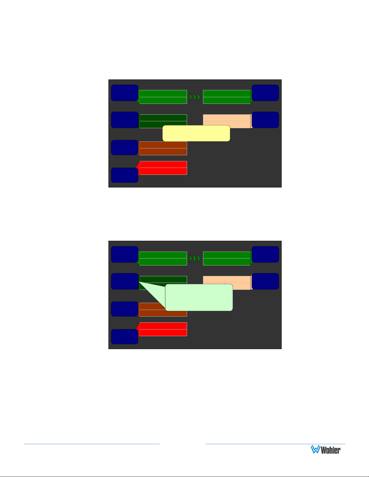
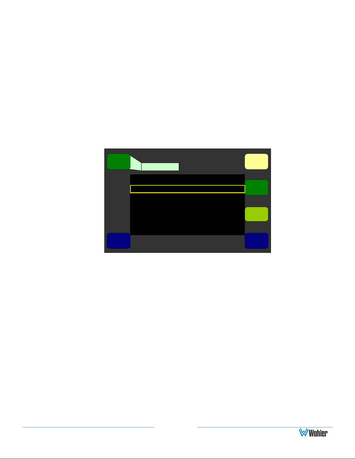
Help
If at any time you would like assistance with the function of any control, pressing
the Help button starts the context-sensitive help for the screen as shown in Figure
1–3 below.
Figure 1–3: Screen/Menu Help
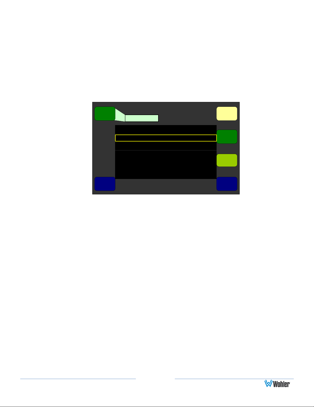
You can display help for any individual knob or button. For example, press the Help
button on any screen and then press one of the menu/ screen controls to display
help specific to that control. See Figure 1–4 below.
Figure 1–4: Individual Control Help
If you do not press/rotate any other controls, the help will disappear from the
screen in approximately 15 seconds.
Page 5
Monitor Mixer Configuration Menu
Save / ExitHelp Cancel
Chan 1 Chan 2 Chan 3 Chan 4
Slot 2 SDI-3G In
Pair 4
Slot 2 SDI-3G In
Pair 5
+0 +0 +0+0
Channel
Trim
Source
Pair
Select
Phase
LED
On/Off
Delay to Speakers = 170 mS
Audio
Delay
Dolby 5.1
Speaker
Mute:
Off
L Front R Front Center LFE
Channel
Func
Mixer
Channel
Select
Set
Clusters
Setting Up Your Monitor for the First Time
To set up your monitor quickly and efficiently, we recommend that you set up your
initial configuration in the order listed below.
1. Configure the Monitor Mixer: Select the inputs to be monitored.
2. Create channel clusters: Cluster the monitored channel meters to make them
most readable.
3. Arrange the Main Screen: Configure the Main Screen arrangement.
4. Select the metadata to display on the screen (if you want to display
metadata).
5. Save your setup into a preset.
Press the Menu button on the Main Screen to display the Configuration
Selection Menu.
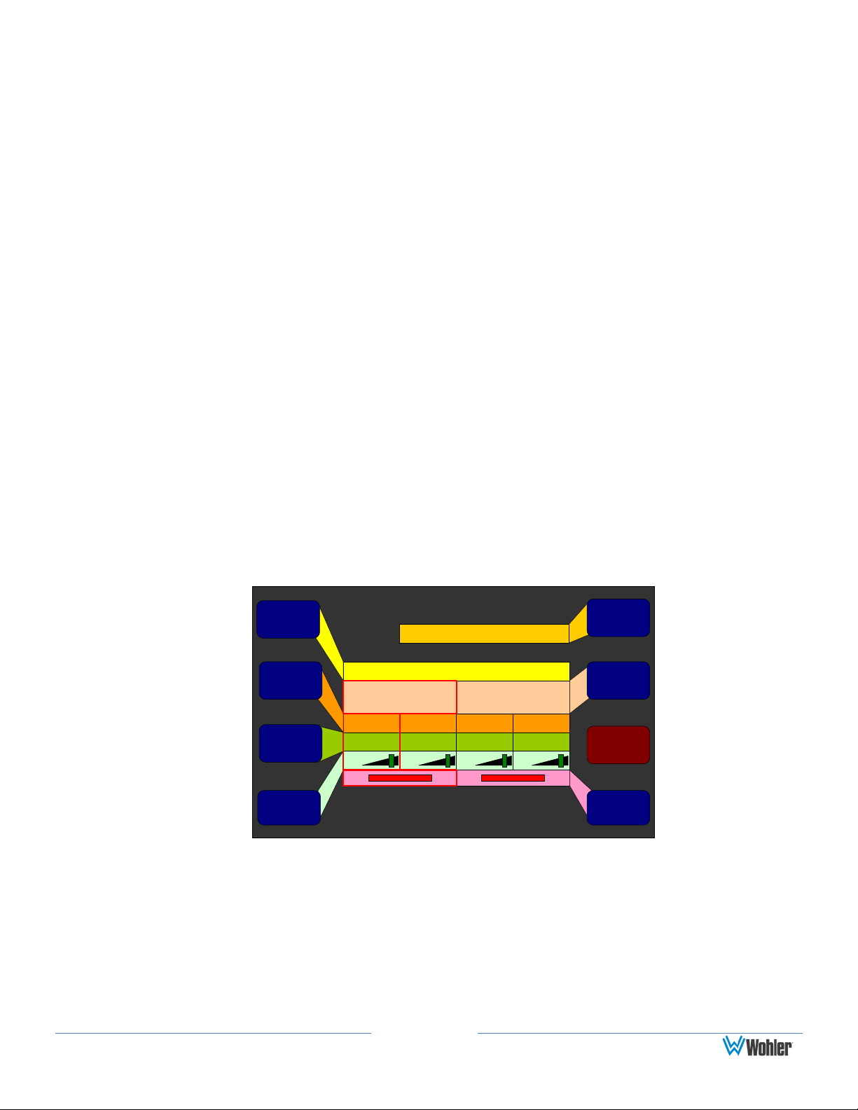
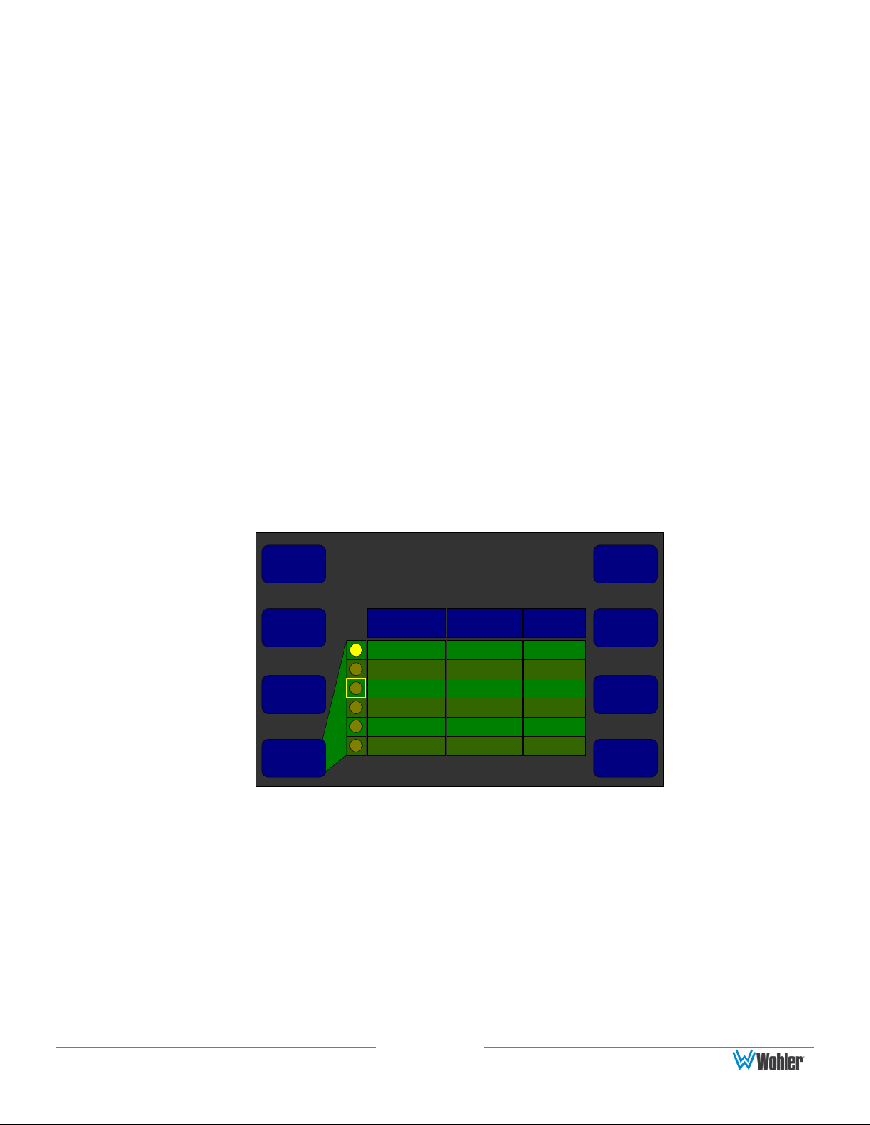
1. Configure the Monitor Mixer
While the Monitor Mixer Configuration Menu (Figure 1–5) provides a number of
feature adjustments, only a few are needed for you to get started. (The other
feature adjustments are explained later in this manual in Chapter 5: Menu List.)
1. To get to the Configure Monitor Mixer Menu, press the Menu button to
enter the Configuration Selection Menu and then press the Configure
Monitor Mixer knob.
2. Before setting up the monitor mixer, it is wise to plan where you want each
channel you need to monitor to appear on the metering screen. Table 1–1
may help.
Figure 1–5: Monitor Mixer Configuration Menu

Page 6
Channel
Number
Cluster Name
(Ex: 5.1
Dolby)
Channel
Source (Ex:
Slot 2: 3G-SDI
In/Pair 4)
Channel Function (Circle One)
1
L R Lfe Ls Rs Lrs Rrs Lfh Rfh Lrh Rrh Ms N
2
L R Lfe Ls Rs Lrs Rrs Lfh Rfh Lrh Rrh Ms N
3
L R Lfe Ls Rs Lrs Rrs Lfh Rfh Lrh Rrh Ms N
4
L R Lfe Ls Rs Lrs Rrs Lfh Rfh Lrh Rrh Ms N
5
L R Lfe Ls Rs Lrs Rrs Lfh Rfh Lrh Rrh Ms N
6
L R Lfe Ls Rs Lrs Rrs Lfh Rfh Lrh Rrh Ms N
7
L R Lfe Ls Rs Lrs Rrs Lfh Rfh Lrh Rrh Ms N
8
L R Lfe Ls Rs Lrs Rrs Lfh Rfh Lrh Rrh Ms N
9
L R Lfe Ls Rs Lrs Rrs Lfh Rfh Lrh Rrh Ms N
10
L R Lfe Ls Rs Lrs Rrs Lfh Rfh Lrh Rrh Ms N
11
L R Lfe Ls Rs Lrs Rrs Lfh Rfh Lrh Rrh Ms N
12
L R Lfe Ls Rs Lrs Rrs Lfh Rfh Lrh Rrh Ms N
13
L R Lfe Ls Rs Lrs Rrs Lfh Rfh Lrh Rrh Ms N
14
L R Lfe Ls Rs Lrs Rrs Lfh Rfh Lrh Rrh Ms N
15
L R Lfe Ls Rs Lrs Rrs Lfh Rfh Lrh Rrh Ms N
16
L R Lfe Ls Rs Lrs Rrs Lfh Rfh Lrh Rrh Ms N
Table 1–1: Channel List
3. To select the inputs that will source each of the displayed and monitored pairs,
rotate the Mixer Channel Select knob to the channel pair and then use the
Source Pair Select to pick a channel pair from the available inputs.
4. Then use the Channel Function to assign a function such as Left Front,
Center, Left Surround, or whatever function you want this channel to have.
This assignment affects how this signal is treated in other parts of the AMP216V, and is essential for correct monitoring operation, especially in terms of
the speaker mix, the loudness measurement, and external surround
positioning.
After you have completed this process for all the channels you want to monitor, you
are ready to move on to the Cluster Configuration Menu.
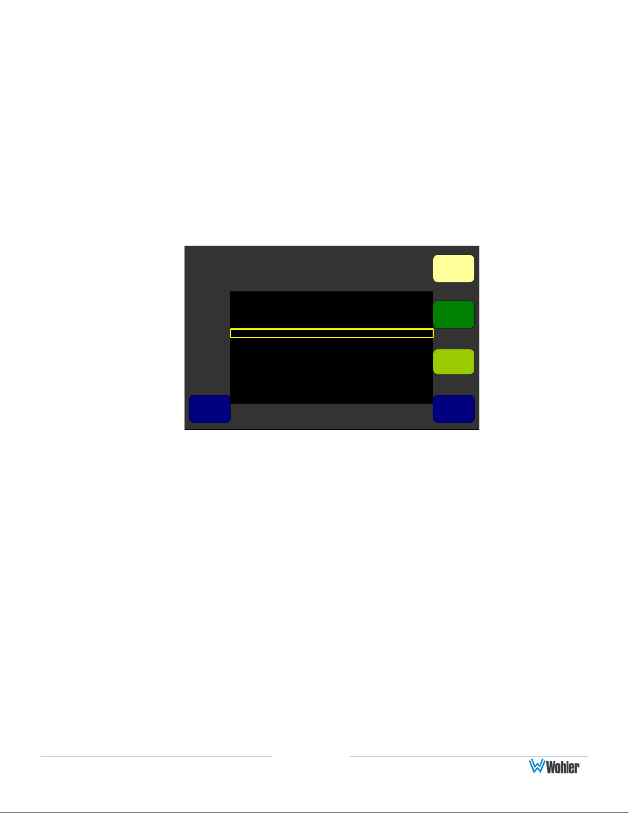
2. Create Channel Clusters
In the Cluster Configuration Screen, you will group, or cluster the channels
together which you consider to be related. For example, if you have set up a
discrete 5.1 set of channels (L Front, R Front, Center, LE, L Sur, and R Sur), then
you will want to cluster them together.
1. From the Monitor Mixer Configuration Menu, press the Set Cluster knob
to display the Cluster Configuration Screen (Figure 1–6).
Page 7
d
00
-60-60
-50
-40
-30
-10
-20
-10
-20
-30
-40
-50
P
a
i
r
1
P
a
i
r
2
P
a
i
r
3
P
a
i
r
4
P
a
i
r
5
P
a
i
r
6
P
a
i
r
7
P
a
i
r
8
Cluster Configuration Screen
Save / ExitHelp Cancel
1 2
Cluster
Start
Edit
Cluster
Label
Cluster
End
Select
Cluster
Default
2
Cluster Configuration Screen
Auto Set
Label Menu
Save / ExitHelp Cancel
Backspace
Select
Vert
Select
Existing
Label
Shift
Select
Horiz
Revert
a b c d e f g h i j k l m
n o p q r s t u v w x y z
0 1 2 3 4 5 6 7 8 9
<SPACE> & ( ) . / \ < > - [ ]
Mine Annc.
Stm1 Jack7
Three Msc.
Music2 Dolby 5.1
d
Cursor
Control
Label Text
Figure 1–6: Cluster Configuration Screen
2. Press the Auto Set control to automatically adjust the cluster arrangements
to match the Channel Function settings made in the Monitor Mixer
Configuration Menu.
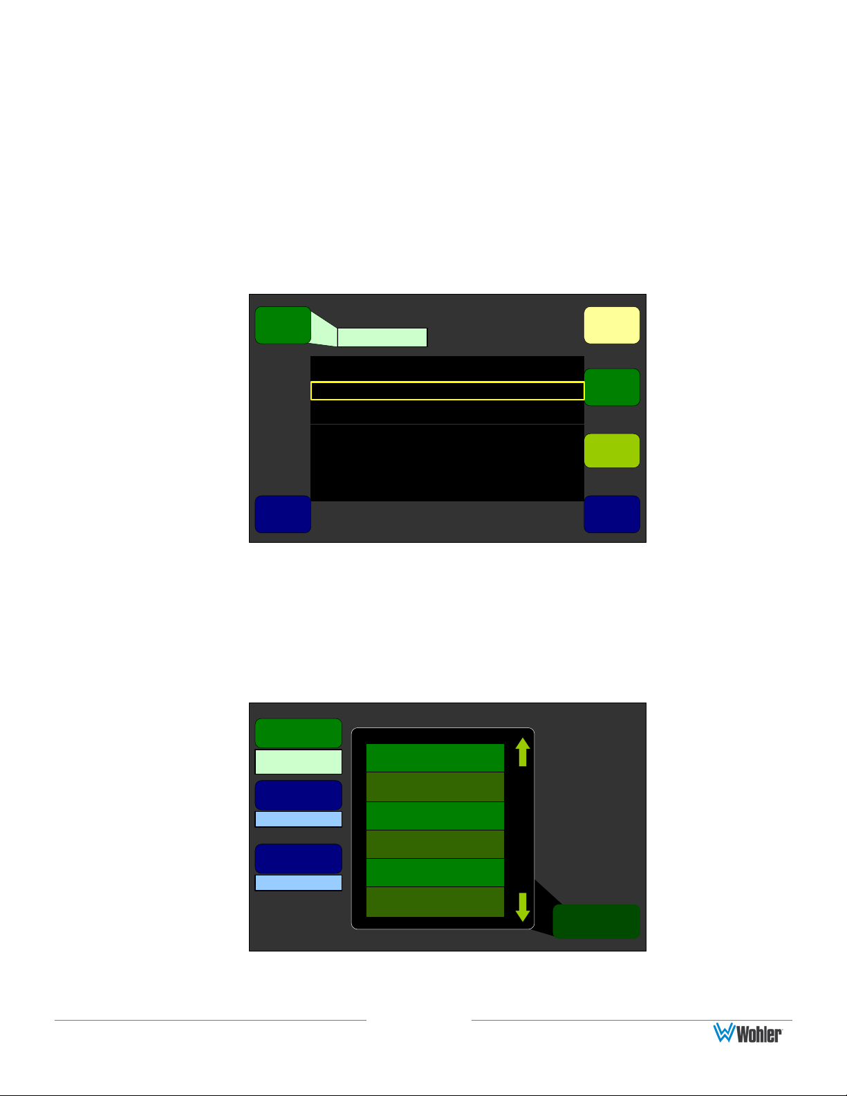
3. Add the cluster name that is to appear on the Main Screen. Rotate the
Select Cluster knob to the cluster you want to name.
4. Press the Edit Cluster Label to display the Label Menu (Figure 1–7).
If you see a label in the Select Existing Label list that is close to the label you
want, rotate the Select Existing Label knob until that label is highlighted. Then
press the knob to replace the label in the Label field with the selected label.
5. If needed, press the Backspace knob until the unwanted text of the current
label disappears, or rotate the Cursor Control knob to move the cursor to the
location where you want to add text.
6. Use the Shift button to toggle between upper and lower case letters.
Figure 1–7: Label Menu
Page 8
Main Screen Configuration Menu
Help
Configure
Meters
Configure
Loudness
Screen
Content
Left
Screen
Right
Screen
Left Nav
Button
Video Meters Help
MetersData Help
Video/Mtrs Left SwapData
Video/Data Left SwapMeters
Meters Data Help
Save / Exit Cancel
Metadata
Select
Status
Select
Configure
Hot Keys
1 - 8
Configure
Hot Keys
9 - 16
Configure
Arbitrary
Phase
Video/Mtrs Swap BothMtrs/Data
7. Turn the Select Horizontal knob (or the Select Vertical knob) to select the
letter to type. Press the knob to type it.
8. When you have finished typing the name, press Save/Exit to return to the
Cluster Configuration Screen.
9. Repeat Steps 5 through 8 until you have named all the clusters and pairs.
10. When you are finished, press Save/Exit repeatedly until you reach the
Main Screen.
3. Arrange the Main Screens
Depending on your needs, the Main Screen provides a number of arrangements
from which you can choose.
1. From the Main Screen, press Menu to display the Configuration Selection
Menu.
2. From the Configuration Selection Menu, press the Config Main Screen
knob to display the Main Screen Configuration Menu. Refer to Main
Screen Arrangements in Chapter 4 to see how the various screen
arrangements will appear.
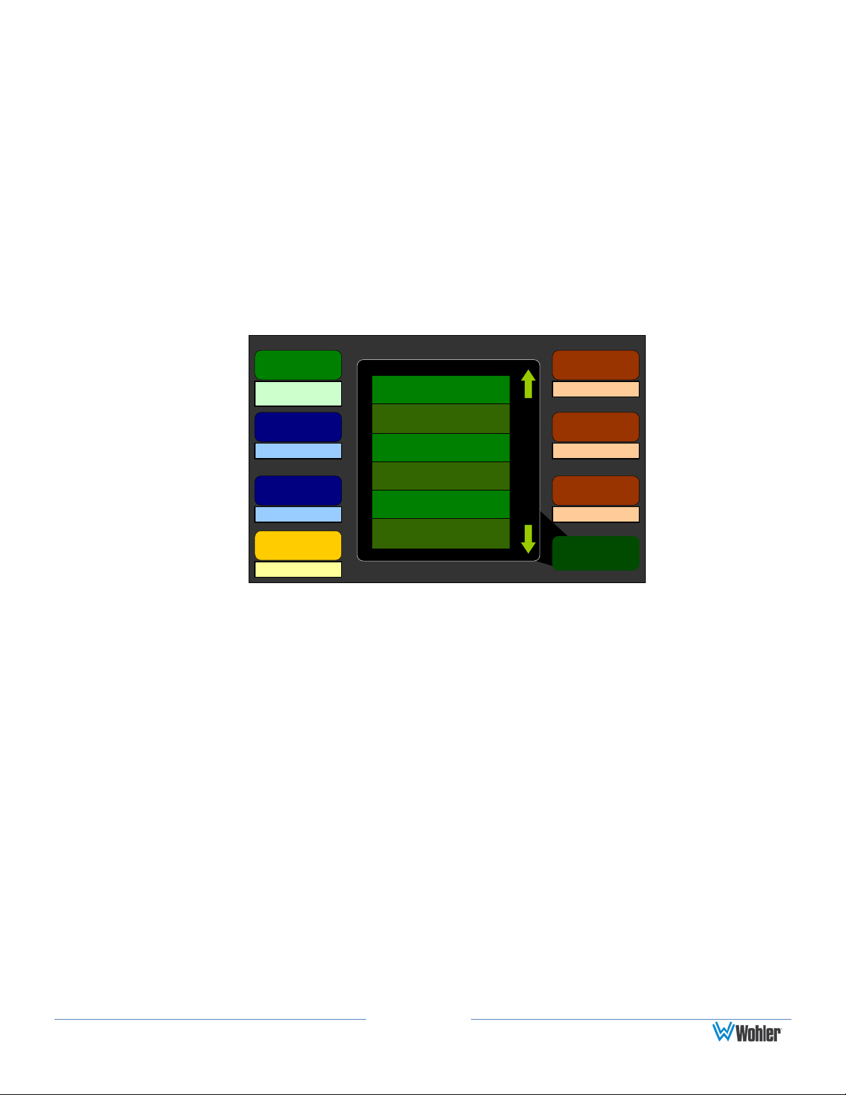
3. When the Main Screen Configuration Menu appears, rotate the Screen
Content knob to select one of the six available arrangements for the left and
right screens (shown in Figure 1–8 above). Rotating the knob moves the
highlight box; pressing the knob makes the selection. (In these cases, the left
navigation button becomes the SWAP button.)
Data refers to metadata, whether from:
1. The optional Dolby D/E / DD+ card,
2. The SMPTE 2020 metadata in an SDI stream, or
3. The status data in an SDI stream.
Figure 1–8: Main Screen Configuration Menu
Page 9
Status Select Menu
Help Save / Exit Cancel
Line
Select
Status
Page 3
Text
Color
Font
Size
Data
Select
Preset Name
Dolby Line Position Pair 5: N/P
Dolby Line Position Pair 6: N/P
(HD) 1920x1080/29.97i
SDID Embedding Method: B
[Empty]
Dolby Line Position Pair 1: 24
Dolby Line Position Pair 2: N/P
S2020 SDIDs Present: 1
S2020 Line Number: 14
Dolby Line Position Pair 3: N/P
Dolby Line Position Pair 4: N/P
If you select a Main Screen arrangement that includes data, proceed to the
following section to specify exactly what data you want to display.
4. Select the Metadata to Display on the Screen
Status Data:
If you do not wish to display status data, continue on to SMPTE 2020
Metadata on the next page.
1. From the Main Screen Configuration Menu, press the Status Select knob
to display the Status Select Menu (Figure 1–9).
Figure 1–9: Status Select Menu
Note: The Lines of data on this display are arranged exactly as they will
appear on the Main Screen.
2. Rotate the Line Select knob to scroll the highlight up or down among the
lines of text to select the line you want to modify.
3. Rotate the Data Select knob to select the type of data you want to display on
this line. (If you select [Empty] a blank line will result on the Main Screen.
This can be used to separate the data lines so they are easier to read.)
4. Rotate the Text Color knob to select the text color of your choice. Use
brighter colors for data that is more important to you, or dim colors for data
that is less important.
5. Rotate the Font Size knob to select from a small, medium, or large font,
according to the importance of the data.
6. Rotate the Status Page knob clockwise to select among the three available
pages.
7. Repeat Steps 2 through 6 for Pages 2 and 3 as needed.
Page 10
Metadata Select Menu
Help Save / Exit Cancel
Line
Select
Metadata
Page 3
Text
Color
Font
Size
Metadata
Select
SMPTE 2020
Program Description
[Empty]
Dolby Digital Sample Rate
RF Compression Profile
Center/Surround Mix Lev
Stereo Downmix
LtRt Cntr/Srnd Downmix Level
LFE Lowpass Filter
Original Bitstream
Dialogue Level
Press to Configure
Metadata
Source
SMPTE 2020 Configuration Menu
Save / ExitHelp Cancel
SMPTE 2020
Source
SMPTE SDID
Dolby E
Program
Slot 1 (3G SDI
I/O)
Auto Select
Program 1
Mdata Scroll
Program ID
1
Program Description
Coding Mode
1/0 (C)
Bitstream Mode
Complete Main
Dialogue Level
- 27 dBFS
Frame Rate
29.97 fps
8. Once you have defined all the status data you want to display, press
Save/Exit to return to the Main Screen Configuration Menu.
SMPTE 2020 Metadata:
You can display either SMPTE 2020 or Dolby metadata. If you prefer to
display Dolby metadata, skip to Dolby Metadata.
1. From the Main Screen Configuration Menu, press the Metadata Select
knob to display the Metadata Select Menu.
Figure 1–10: Metadata Select Menu
2. Rotate the Metadata Source knob to display SMPTE 2020, rather than
Dolby Decoder.
3. Press the Metadata Source knob to display the SMPTE 2020
Configuration Menu. Figure 1–11: SMPTE 2020 Configuration Menu
4. Rotate the SMTPE 2020 Source to select the input card from which the
Figure 1-11: SMPTE 2020 Configuration Menu
Page 11
Metadata Select Menu
Help Save / Exit Cancel
Line
Select
Metadata
Page 3
Text
Color
Font
Size
Metadata
Select
SMPTE 2020
Program Description
[Empty]
Dolby Digital Sample Rate
RF Compression Profile
Center/Surround Mix Lev
Stereo Downmix
LtRt Cntr/Srnd Downmix Level
LFE Lowpass Filter
Original Bitstream
Dialogue Level
Press to Configure
Metadata
Source
metadata is to be extracted. The possible choices include any of the
3G/HD/SD SDI cards.
5. By default, the AMP2-16V will automatically select the lowest numbered
SDID containing metadata. If you would prefer to specify a different SDID,
rotate the SMPTE SDID to select the desired SMPTE SDID. The ten choices
include No Assoc., Pair 1 through Pair 8 and Auto Select.
6. Rotate the Dolby E Program knob to select the desired Dolby E program.
7. Press Save/Exit to return to the Metadata Select Menu (Figure 1–12
below).
Note: Any text line can contain any metadata element.
Figure 1–12: Metadata Select Menu
8. Rotate the Line Select knob to scroll the highlight up or down among the
lines of text to select the one you want to modify.
9. Rotate the Metadata Select knob to select the type of data you want to
display on this line. (If you select [Empty] a blank line will result on the
Main Screen. This can be used to separate the data lines so they are easier
to read.)
10. Rotate the Text Color knob to select the text color of your choice. Use
brighter colors for data that is more important to you, or dim colors for data
that is less important.
11. Rotate the Font Size knob to select from a small, medium, or large font,
according to the data line’s importance.
12. Rotate the Status Page knob clockwise to select among the three available
pages.
13. Repeat Steps 2 through 12 for Pages 2 and 3 if needed.
Page 12
Dolby Decoder Configuration Menu
Save / ExitHelp Cancel
Decoder Source
Pro-16 Mode
Channel
Dolby E
Program
Slot 1 (AES
In) Pair 1
Channel 1
Program 1
Decode
Aux Pair
DRC Mode
All formats
LtRt Downmix
Line Mode
Coding Mode
1/0 (C)
Bitstream Mode
Complete Main
Dialogue Level
- 27 dBFS
Frame Rate
29.97 fps
LFE Channel
Disabled
Surround Mode
Not Srnd Encoded
Mdata Scroll
CRC Error
Reporting
On
14. Once you have defined all the status data you want to display, press
Save/Exit to return to the Main Screen Configuration Menu.
Dolby Metadata:
Note:
this option.
1. On the Metadata Select Menu, rotate the Metadata Source knob to
display Dolby Decoder, rather than SMPTE 2020.
2. Press the knob when Dolby Decoder displays to display the Dolby Decoder
Configuration Menu.
Figure 1–13: Dolby Configuration and Metadata Display Menu
Only units equipped with an optional Dolby D/E/DD+ card will show
3. Rotate the Decoder Source knob to select the source for the Dolby
D/E/DD+ Card. The choices include all available AES input pairs, all available
SDI de-embedded pairs, and Dolby Zoom Select.
4. Rotate the Pro-16 Mode Channel knob to select the stream to decode when
two are present in the decoder source pair.
5. Rotate the Dolby E Program knob to select the Dolby E program. If the
selected program is not available, the metadata from Program 1 will display.
6. Press the CRC Error Reporting knob to toggle Main Screen
7. CRC error reporting and counting on or off.
8. Rotate the Decode knob selects the Dolby stream to decode. The available
options include: All Formats, Dolby D Only, or Dolby E Only.
9. Rotate the Aux Pair knob to select how the Auxiliary Dolby Pair will be
treated. The available options include: Mute, Mono, LoRo Downmix, or
LtRt Downmix.
10. Rotate the DRC Mode knob to select the DRC Mode. The available options
Page 13
Metadata Select Menu
Help Save / Exit Cancel
Line
Select
Metadata
Page 3
Text
Color
Font
Size
Metadata
Select
SMPTE 2020
Program Description
[Empty]
Dolby Digital Sample Rate
RF Compression Profile
Center/Surround Mix Lev
Stereo Downmix
LtRt Cntr/Srnd Downmix Level
LFE Lowpass Filter
Original Bitstream
Dialogue Level
Press to Configure
Metadata
Source
are None, Dialnorm Only, Line Mode, or RF Mode.
11. Rotate the Metadata Scroll knob to scroll through the list of available
Dolby metadata items. The metadata items in the list are actively refreshed
by the software, and will change to reflect changes in the selected input
stream.
12. When you have completed making your selections on the Dolby Decoder
Configuration Menu, press Save/Exit to return to the Metadata Select
Menu.
Figure 1–14: Metadata Select Menu
Note: Any text line can contain any metadata element.
15.Rotate the Line Select knob to scroll the highlight up or down among the
lines of text to select the line you want to modify.
16.Select the Text Color, Font Size, and the Metadata Select as you did
previously.
17.Repeat Steps 13 through 14 for Pages 2 and 3 as needed.
18.Press the Save/Exit button twice to return to the Configuration Selection
Menu.
5. Save Your Setup in a Preset
Now that you have a basic configuration for your system, you will need to save it as
a preset so you can reconfigure this way quickly and easily. Note that if you make
any change(s) in the menu settings and return to the Main Screen without saving
them into a preset, a yellow warning flag will appear on the Main Screen reminding
you to do so.
Refer to Figure 1-15 and perform the following steps.
Page 14
Preset Management Menu
Save / ExitHelp Cancel
Preset 4:
User Preset 4
Preset 1:
User Preset 1
Preset 1:
User Preset 1
Current Config
Current Settings
Preset 1:
User Preset 1
Preset 4:
User Preset 4
Clear
Preset
Rename
Preset
Save
Current
Config
Copy
From
Copy To
Recall
On
Powerup
Figure 1–15: Preset Management Menu
1. From the Main Screen, press Menu to display the Configuration Selection
Menu.
2. From the Configuration Selection Menu, press the Manage Presets knob
to display the Preset Management Menu.
3. Rotate the Save Current Config control to the number of the preset you
would like to save the configuration into and then press the knob.
4. You will be presented with the opportunity to name the preset. Typically a
short name describing the use of the configuration is appropriate. For
example, if the preset will select a number of AES channels for monitoring,
name the preset, AES.
Getting Support
Should you need to contact Wohler’s customer support line (see page ii for our
contact information), you will save time on the phone by writing down the software
and hardware versions installed in your monitor. Refer to the How Do I Find
Software Version Information? section in Chapter 3 of this manual for instructions.

Page 15
WARNING:
Do not use this equipment near water, rain or moisture.
IMPORTANT:
By design, these monitors will only plug into a three-prong outlet
for your safety. If the plug does not fit into your outlet, contact an
electrician to replace the obsolete outlet.
CHAPTER 2: Installation
Introduction
Overview
This chapter describes how to install the AMP2-16V Series monitor into a standard
19” rack and how to connect the necessary wiring.
Important Safety Instructions
1. Read, keep, and follow all of these instructions; heed all warnings. Use only a
dry cloth to clean the equipment.
2. Do not block any ventilation openings. Install only in accordance with the
instructions in the section entitled, Installation Recommendations.
3. Do not install near any heat source such as a radiator, heat register, amplifier,
or stove.
4. Do not attempt to plug the unit into a two-blade outlet (with only two prongs
of equal width).
5. Protect the power cord from being walked on or pinched, particularly at
plug’s source on the equipment and at the socket.
6. Use only the attachments/accessories specified by the manufacturer.
7. Unplug the equipment during lightning storms or when unused for long
periods of time.
8. Use of a cart is neither recommended nor approved by Wohler.
9. Refer all servicing to qualified service personnel. Servicing will be required
under all of the following conditions:
a) The equipment has been damaged in any way, such as when the
power-supply cord or plug is damaged.
b) Objects have fallen onto the equipment; or the equipment has been

Page 16
Clearance
Surface
24”
Front
3”
Rear
2”
Sides
1.75”
Top and Bottom (if either radiates heat)
0”
Top and Bottom (if no heat)
Important
To reduce noise, the monitor does not have any fans. As a result,
the heat generated by the class D power amplifiers, power
supplies, and other components is vented by slots in the side of
the unit. Therefore, as a safety precaution, you must allow proper
ventilation on both sides of the unit.
exposed to rain or moisture, or liquid has been spilled onto the
equipment.
c) The equipment does not operate normally.
d) The equipment has been dropped.
Installation Recommendations
Mounting
The unit is designed to install into a standard 19" rack mounted at ear level for best
high frequency response and visual observation of the monitor screen. Please
adhere to the following clearances:
Heat Dissipation
The ambient temperature inside the mounting enclosure should not exceed 40°
Celsius (104° Fahrenheit). Adjacent devices can be rack mounted (or stacked) in
proximity to the unit if this temperature is not exceeded. Otherwise, allow a 1RU
(1.75”/44.45mm) space above and below the unit for air circulation.
Sympathetic Vibration
Sympathetic vibration from other equipment (cables, etc.,) in the rack may be
serious enough to interfere with the unit’s sound quality. The use of thin card stock
and/or felt or foam weather-stripping type materials between adjacent vibrating
surfaces, or tying up loose cables, etc., may be required to stop vibrations external
to the unit.
Mechanical Bracing
Even though these 2U models are fairly heavy, the chassis is securely attached to
the front panel. In addition, the chassis has mounting tabs through which you
attach it to the rack rail. This feature will reduce or eliminate rear bracing
requirements in many mobile/portable applications. The weight of internal
components is distributed fairly evenly around the unit.

Page 17
Connections and Cable Recommendations
We recommend that you limit the length of the cables that you use for feeding HDSDI signals sources to the HD-SDI inputs of the AMPx-E8 Series units and that you
use a Belden 1694A cable (or equivalent). The HD-SDI inputs (In 1 and In 2) can
be up to 150 meters (492 feet) in length when used with HD signals and 75 meters
(246 feet) in length when using 3G signals.
Note: The connections of all DB-25 connectors are compatible with Tascam DB-25
to XLR cable assemblies. Consult the factory for availability. All rear panel
connectors are female.
Electrical Interference
Be careful to apply proper input termination settings and avoid mismatched cable
types and other similar causes of undesired reflections in digital signal systems. If
severe enough, such reflections can result in corruption of the digital data stream.
As with any audio equipment, maximum immunity from electrical interference
requires the use of shielded cable. The internal circuitry ground is connected to the
chassis.
Power
The unit comes with one 100 - 240 VAC +/- 10%, 150W, 50/60Hz power supply
module. A second identical module is an optional accessory for use when
redundancy is necessary. These modules plug in to the back panel and are secured
with thumbscrews. The power to each supply connects an A/C mains power source
through the IEC connector provided on the back panel of each power supply.
When the mains plug or appliance coupler is used as the disconnect device, the
disconnect device should remain operable.
Compliance
FCC
This equipment has been tested and found to comply with the limits for a Class A
digital device, pursuant to part 15 of the FCC Rules. These limits are designed to
provide reasonable protection against harmful interference when the equipment is
operated in a commercial environment. This equipment generates, uses, and can
radiate radio frequency energy and, if not installed and used in accordance with the
instruction manual, may cause harmful interference to radio communications.
Operation of this equipment in a residential area is likely to cause harmful
interference in which case the user will be required to correct the interference at his
own expense.
ICES-003
This Class A digital apparatus complies with Canadian ICES-003.
Cet appareil numérique de la classe A est conforme à la norme NMB-003 du
Page 18
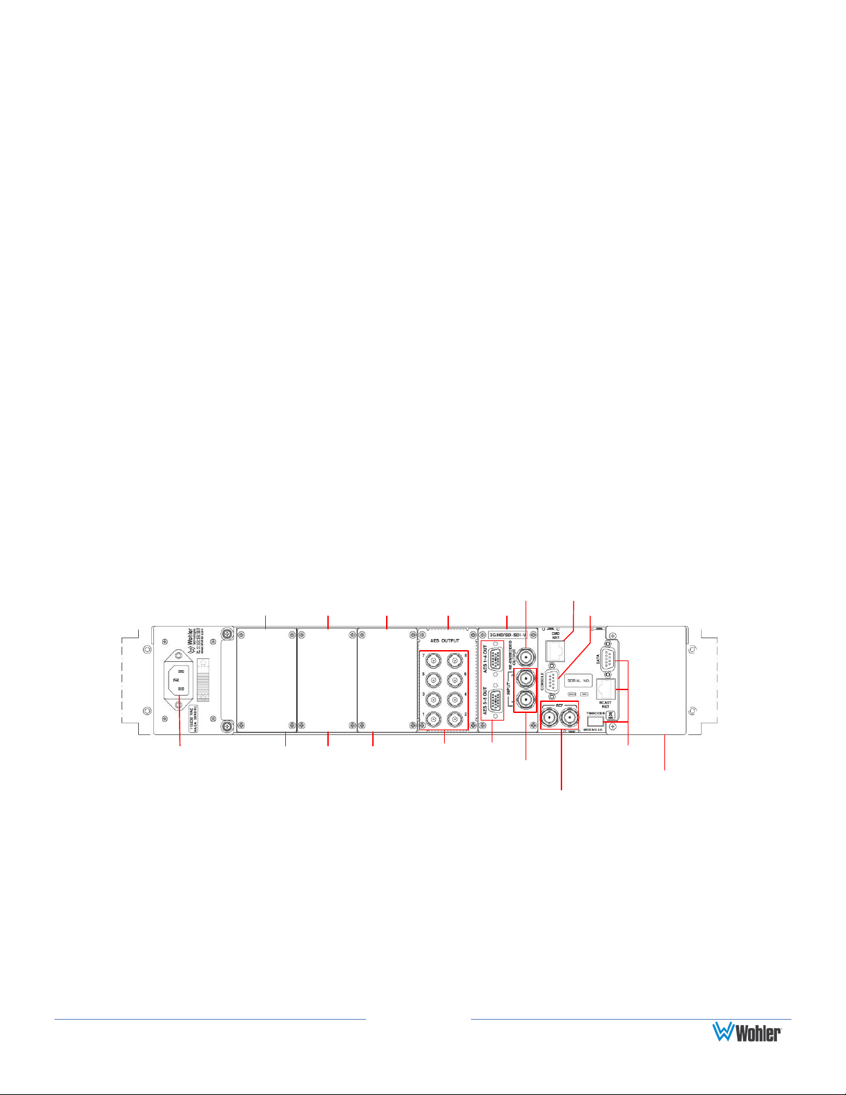
UnusedAES Outputs
3G/HD/SD-
SDI Inputs
Genlock Ref Input
and Pass Through
Blank Cover Plate for
Optional Redundant
Power Supply
Blank Cover Plates for
Additional I/O Modules
IEC Power
Connector
Slot 1Slot 2Slot 3Slot 4Slot 5 Serial Port
Ethernet Port
Re-embedded
SDI Output
Canada.
Rear Panel Connectors
Standard Connectors
The AMP2-16V Series monitor back panel contains all of the connectors except for
the headphone jack as shown in Figure 2–1. Note that, as you are facing the rear
panel, the audio module slots are numbered from right to left.
1. Power: The AMP2-16V Series monitors use a standard IEC power cord for
the 100 to 240 VAC power connection. A redundant power supply is optional.
(Refer to Table 6-7 for a complete list of Option Kits).
2. Ethernet: The Ethernet port is used for system software upgrades.
3. Serial (Console): This DB-9F connector is used for factory diagnostic
purposes.
4. Genlock Ref Input and Pass-Through (Ref): These BNC connectors are
designed to be used in a daisy-chained series arrangement from unit to unit.
A 75Ω BNC terminator (not supplied) must be installed in the open Ref
connector of the last unit in the chain. These inputs accept composite video
sync sources.
Figure 2–1: Typical Back Panel Layout
Optional I/O Modules and Rear Panel Connectors
The AMP2-16V Series monitors can include any combination of the optional I/O
modules listed in Table 2–1.

Page 19
I/O Module Name
I/O Module Description
3G/HD/SD-SDI-V Card
Two 3G/HD/SD-SDI inputs
8 de-embedded AES pairs outputs
1 selected reclocked or re-embedded
output (Includes automatic frame rate
detection)
AES Input Card
16 channel (eight unbalanced AES pairs)
AES Output Card
16 channel (eight unbalanced AES pairs)
Analog I/O Card
8 balanced channels in and 8 balanced channels
out
Analog I/O SPDIF TOSLINK Card
8 balanced channels in, 8 balanced channels
out,
and 1 optical SPDIF (TOSLINK) input
AVB Listener Card
Provides capability to listen to two AVB streams
carrying up to 8 audio channels in each
stream, for a total of 16 channels.
Dante/AES67 (AoIP) Card
16 Rx channels of Dante / 8 Rx channels of
AES67
Ravenna/AEC67 (AoIP) Card
16 Rx channels of Ravenna / 8 Rx channels of
AES67
Dolby Card D/E/DD+ Card*
Provides Dolby bitstream decoding for an AES
pair or de-embedded SDI of your choice
Table 2–1: Available Add-On I/O Modules
* The Dolby D/E/DD+ Card is an internal daughter card. It does not occupy one of
the vacant slots and does not require its own external connectors.
Refer to Table 6-7 for a complete list of Option Kits.
Basic Connections
Usually, the AMP2-16V is sold with a single 3G/HD/SD-SDI-V card in Slot 1. The
instructions below assume this configuration.
1. Install the AMP2-16V into a standard 19” rack as close to eye-level as
possible.
2. Connect power from the unit to A/C mains. If you have purchased a redundant
power supply, verify you are connecting the second power supply to A/C
mains power on a different circuit from the first.
3. Connect an SDI video source to the SDI input connector.

Page 20
CHAPTER 3: The “How Do I...” Chapter
Introduction
Overview
This chapter answers many questions that naturally come up as the AMP2-16V
Series monitor is first put into service.
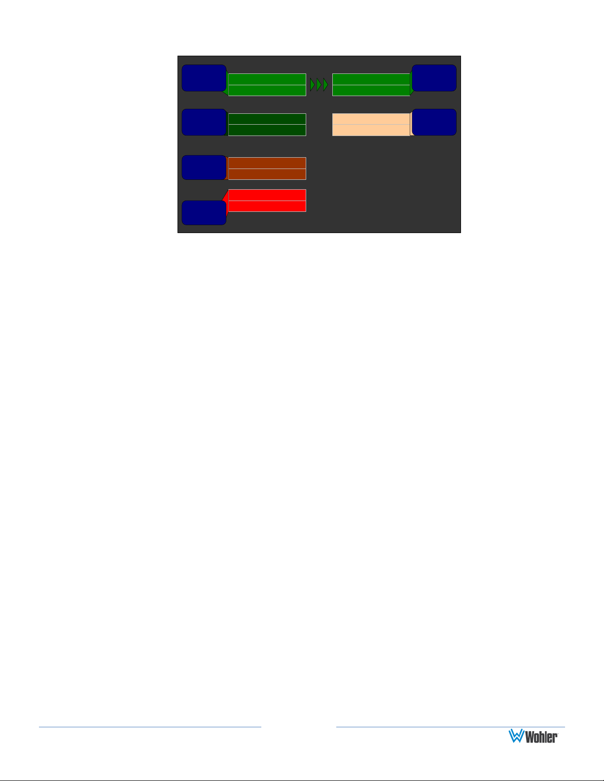
Notation
In this chapter, we use a shorthand method to show you how to progress from the
Main Screen to the menus. See Figure 3–1 below.
Page 21
-28 LKFS
SwapVideo/Data
Meta
+
0
Dolby
Zoom
Pair 6
Recall
MyMix
Anlg
1
Dolby
5.1
AES 1
Down
Mix
Status
Menu
-60
Anlg
2
Configuration Selection Menu
Help
Configure
Main
Screen
Configure
Monitor
Mixer
Manage
Presets
Audio
Processors
Cancel
Input 2
Input 1
Slot 1
SDI Input
Select
Save / Exit
Push knob to recall
User Preset 1
1
Recall
Preset
Configure
Options
Video /
SDI
Source
Monitor Mixer Configuration Menu
Save / ExitHelp Cancel
Chan 1 Chan 2 Chan 3 Chan 4
Slot 2 SDI-3G In
Pair 4
Slot 1 AES In
Pair 1
+
0
+
0
+
0
+
0
Channel
Trim
Source
Pair
Select
Phase
LED
On/Off
Delay to Speakers = 170 mS
Audio
Delay
Dolby 5.1
Speaker
Mute:
Off
L Front R Front Center LFE
Channel
Func
Mixer
Channel
Select
Set
Clusters
Configuration Selection
Menu
Main Screen
Menu
Configure
Monitor Mixer
Monitor Mixer
Configuration Menu
Configuration Selection
Menu
Main Screen
Menu
Configure
Monitor Mixer
Monitor Mixer
Configuration Menu
Figure 3–1: Screen Notation
Or simply:
Page 22
Configuration Selection
Menu
Main Screen
Menu
Configure
Monitor Mixer
Monitor Mixer
Configuration Menu
Monitor Mixer Configuration Menu
Save / ExitHelp Cancel
Chan 1 Chan 2 Chan 3 Chan 4
Slot 2 SDI-3G In
Pair 4
Slot 2 SDI-3G In
Pair 5
+0 +0 +0+0
Channel
Trim
Source
Pair
Select
Phase
LED
On/Off
Delay to Speakers = 170 mS
Audio
Delay
Dolby 5.1
Speaker
Mute:
Off
L Front R Front Center LFE
Channel
Func
Mixer
Channel
Select
Set
Clusters
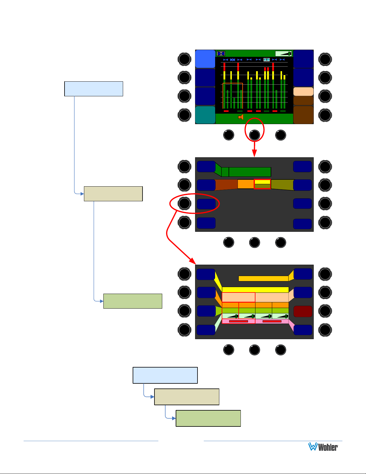
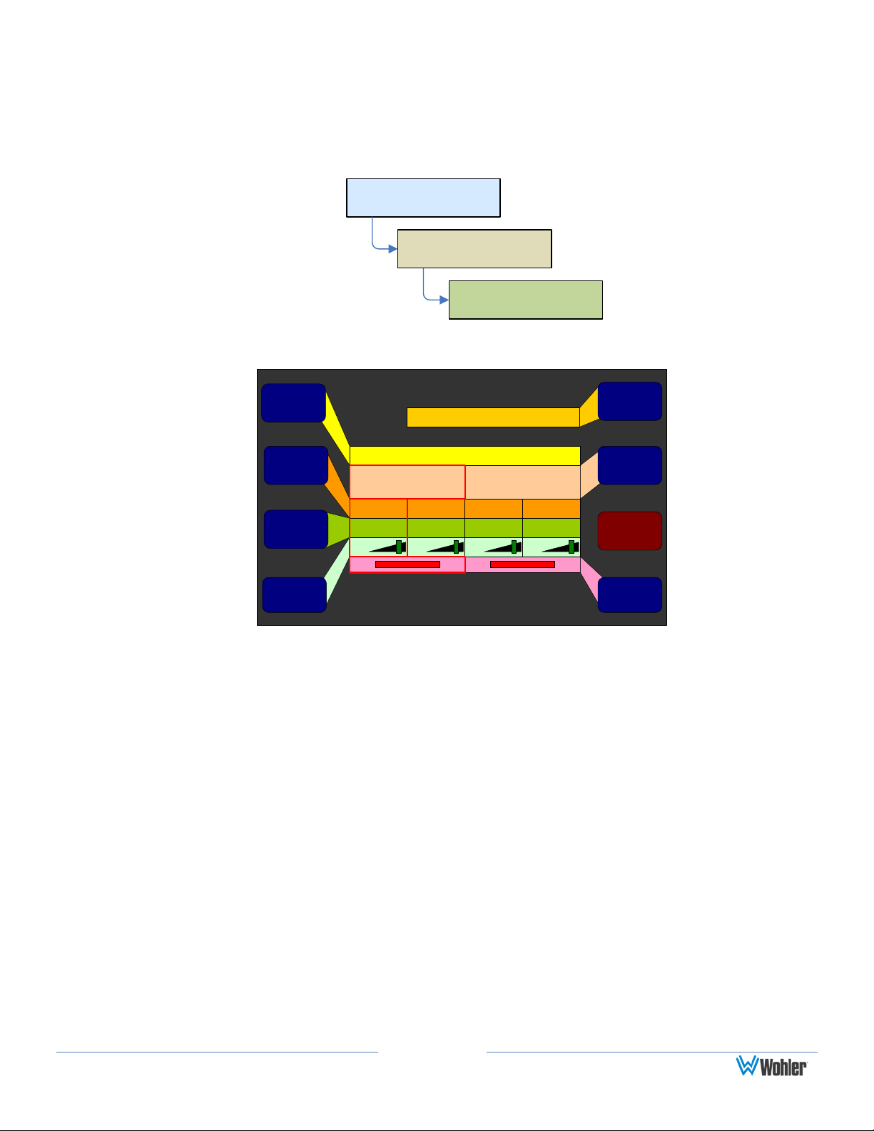
Frequently Asked Questions
How Do I Select the Inputs I Want to Hear in the Speakers?
This selection appears on the Monitor Mixer Configuration Menu.
Figure 3–2: Monitor Mixer Configuration Menu
1. Rotate the Mixer Channel Select knob to select the channel pair to
manipulate.
2. Rotate the Source Pair Select control to select the audio processor card slot
and desired input pair on that card.
3. Now is also a good time to rotate the Channel Function control to designate
the function of each channel in that pair.
Page 23
Configuration Selection
Menu
Main Screen
Menu
Configure
Monitor Mixer
Monitor Mixer
Configuration Menu
Cluster Configuration Screen
Set Clusters
00
-60-60
-50
-40
-30
-10
-20
-10
-20
-30
-40
-50
P
a
i
r
1
P
a
i
r
2
P
a
i
r
3
P
a
i
r
4
P
a
i
r
5
P
a
i
r
6
P
a
i
r
7
P
a
i
r
8
Cluster Configuration Screen
Save / ExitHelp Cancel
1 2
Cluster
Start
Edit
Cluster
Label
Cluster
End
Select
Cluster
Default
2
Cluster Configuration Screen
Auto Set
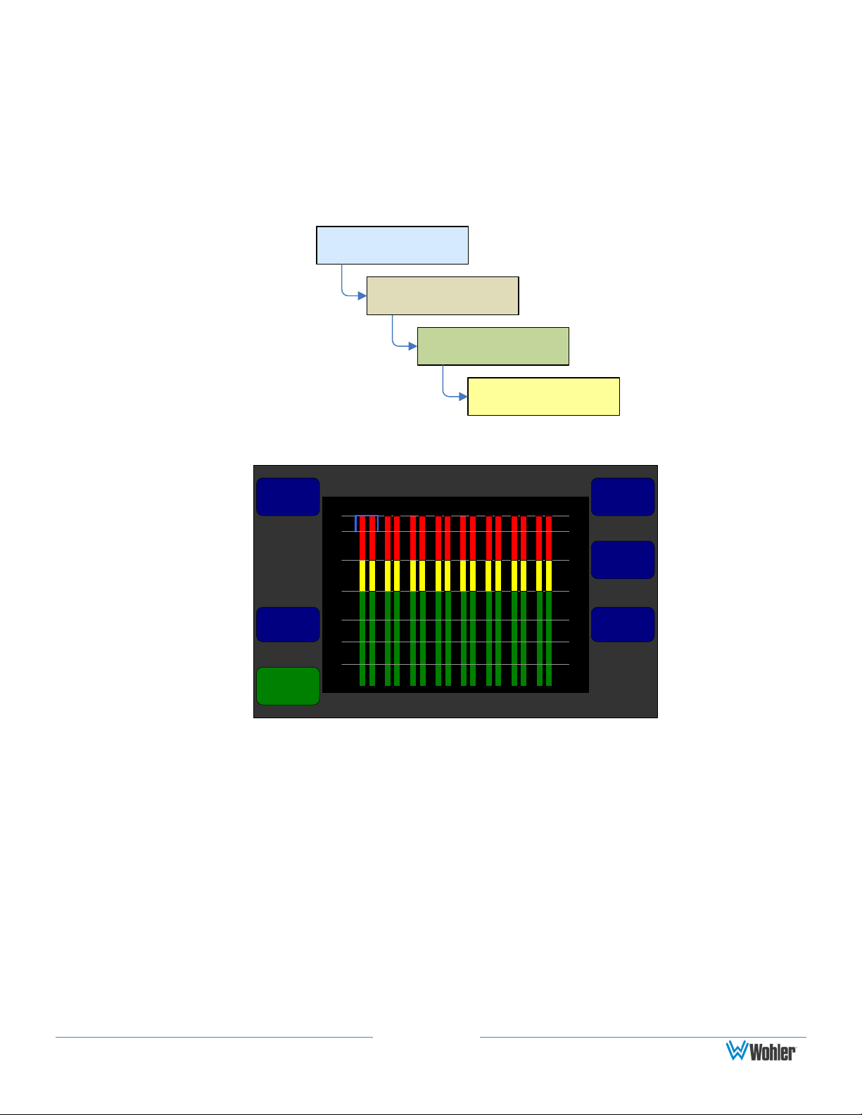
How Do I Cluster Meters Pairs Together for Easy Readability?
Clustering the meter pairs in logical arrangements enhances the at-a- glance
readability of the meters. It also assures that the Loudness calculations are
accurately represented. After setting up the meter clusters, the Cluster Select hot
keys are automatically configured so that they select the clusters you defined.
Meter clustering is done in the Cluster Configuration Screen:
Figure 3–3: Cluster Configuration Screen
1. If you have already assigned the channel functions in the Monitor Mixer
2. Turn the Select Cluster control to select the channel pair that you want the
3. Turn the Cluster End control so that the blue bracket encompasses the
4. Press the Edit Cluster Label control to proceed to a screen that lets you
Configuration Menu, press the Auto Set control and proceed to step 4.
cluster to start on. Note that the blue bracket at the top moves to select the
beginning of the cluster.
channel pairs you want in the cluster. Press the Cluster End control to set
the cluster.
name the cluster. This name will appear on the main screens.
 Loading...